resistors for high voltage applications l · resistors for high voltage applications fixed...
TRANSCRIPT
RESISTORS FOR HIGH VOLTAGE APPLICATIONS
Fixed Resistors
TT electronics offers one of the most diverse ranges of high voltage resistors. Across the HV range from 1 to 100kV productsare available which provide safety in discharge, reliability in balancing and accuracy in measurement. For designers requiring a resistor with parameters outside of this range, bespoke solutions for specific applications may be supplied.
From commercial thick-film & precision high voltage devices to bleeders, dividers and ultra high resistance values (100Tor 1014Ω), products are supplied to key commercial & military standards. RoHS compliant Pb-free finish and SnPb finish are both available across most product families. Because of its ability to
• EN60065 safety bleeders
• Voltage balancing resistors
• Resistive voltage dividers
• LEVs up to 100kV
• Ohmic values to 100TΩ
• Compatibility with oil or SF6 filled assemblies
• MIL-R-49462 approval
maintain good stability of resistivity in the presence of high voltage stress, the technology normally used for compact high voltage resistors is thick-film.
TT electronics companies have been leaders in thick-film product development since the 1960s and can now offer a full range of component styles including compact SMD chips, conventional axial throughhole and space-saving single-in-line (SIL) radial format.
This Application Note gives data, calculations and typical products for use in high voltage circuits. It should be read in conjunction with the full datasheets for each product referenced.
TT electronics companies
• X-ray PSU • AED • Electron Microscope • E-beam Welder
• Electrostatic Precipitator • Air Ioniser • Photomultiplier
• Gas Detector • Lighting Ballast • IR Tester • EL Backlight
• PFC • UPS • ESD Protection • Seismic Monitor • Paint Spray
Logos, and titles contain hyperlinks to other resources.
CDR Inquire• Ratings to 30kV• Non-contaminating, for
use inside oil filled capacitors
RESISTORS FOR HIGH VOLTAGE APPLICATIONS
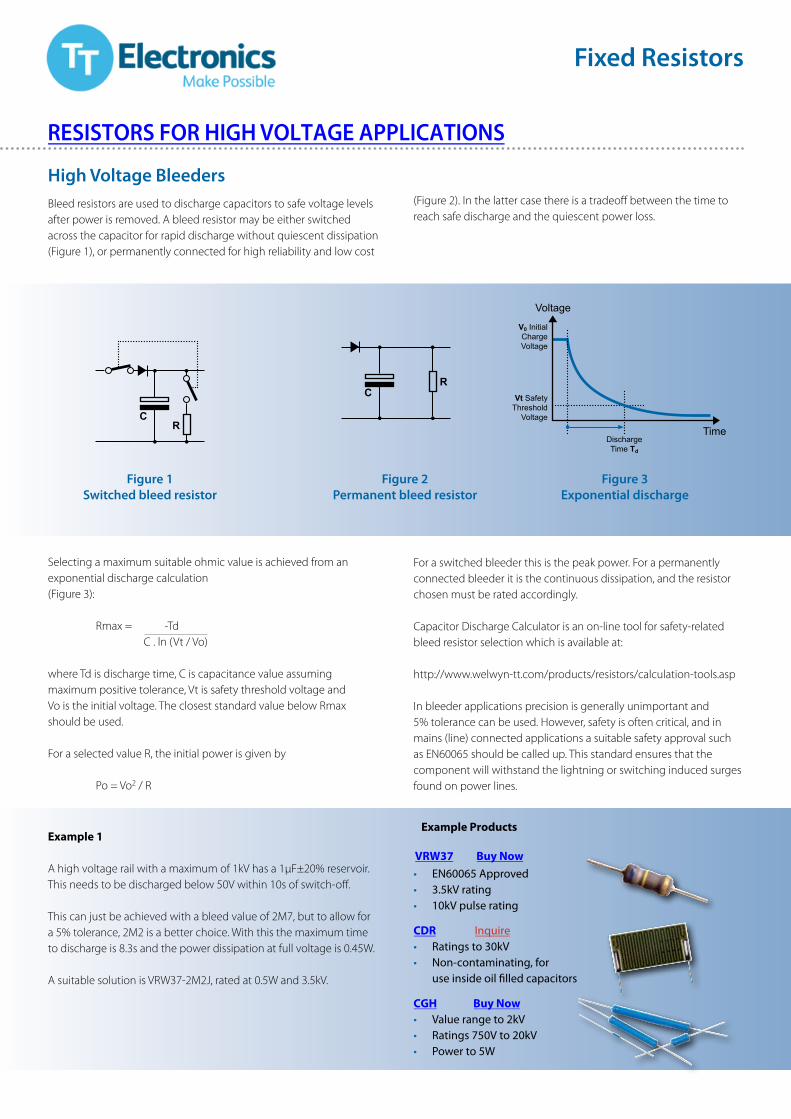
High Voltage Bleeders
Figure 1Switched bleed resistor
Figure 2Permanent bleed resistor
Figure 3Exponential discharge
Bleed resistors are used to discharge capacitors to safe voltage levels after power is removed. A bleed resistor may be either switched across the capacitor for rapid discharge without quiescent dissipation (Figure 1), or permanently connected for high reliability and low cost
Example 1
A high voltage rail with a maximum of 1kV has a 1μF±20% reservoir. This needs to be discharged below 50V within 10s of switch-off.
This can just be achieved with a bleed value of 2M7, but to allow for a 5% tolerance, 2M2 is a better choice. With this the maximum time to discharge is 8.3s and the power dissipation at full voltage is 0.45W.
A suitable solution is VRW37-2M2J, rated at 0.5W and 3.5kV.
(Figure 2). In the latter case there is a tradeoff between the time to reach safe discharge and the quiescent power loss.
For a switched bleeder this is the peak power. For a permanently connected bleeder it is the continuous dissipation, and the resistor chosen must be rated accordingly.
Capacitor Discharge Calculator is an on-line tool for safety-related bleed resistor selection which is available at:
http://www.welwyn-tt.com/products/resistors/calculation-tools.asp
In bleeder applications precision is generally unimportant and 5% tolerance can be used. However, safety is often critical, and in mains (line) connected applications a suitable safety approval such as EN60065 should be called up. This standard ensures that the component will withstand the lightning or switching induced surges found on power lines.
Fixed Resistors
CR
CR
Time
Voltage
DischargeTime Td
Vt SafetyThreshold
Voltage
V0 InitialChargeVoltage
Selecting a maximum suitable ohmic value is achieved from an exponential discharge calculation(Figure 3):
Rmax = -TdC . ln (Vt / Vo)
where Td is discharge time, C is capacitance value assumingmaximum positive tolerance, Vt is safety threshold voltage andVo is the initial voltage. The closest standard value below Rmaxshould be used.
For a selected value R, the initial power is given by
Po = Vo2 / R
Example Products
VRW37 Buy Now• EN60065 Approved• 3.5kV rating• 10kV pulse rating
CGH Buy Now• Value range to 2kV• Ratings 750V to 20kV• Power to 5W
RESISTORS FOR HIGH VOLTAGE APPLICATIONS
Fixed Resistors
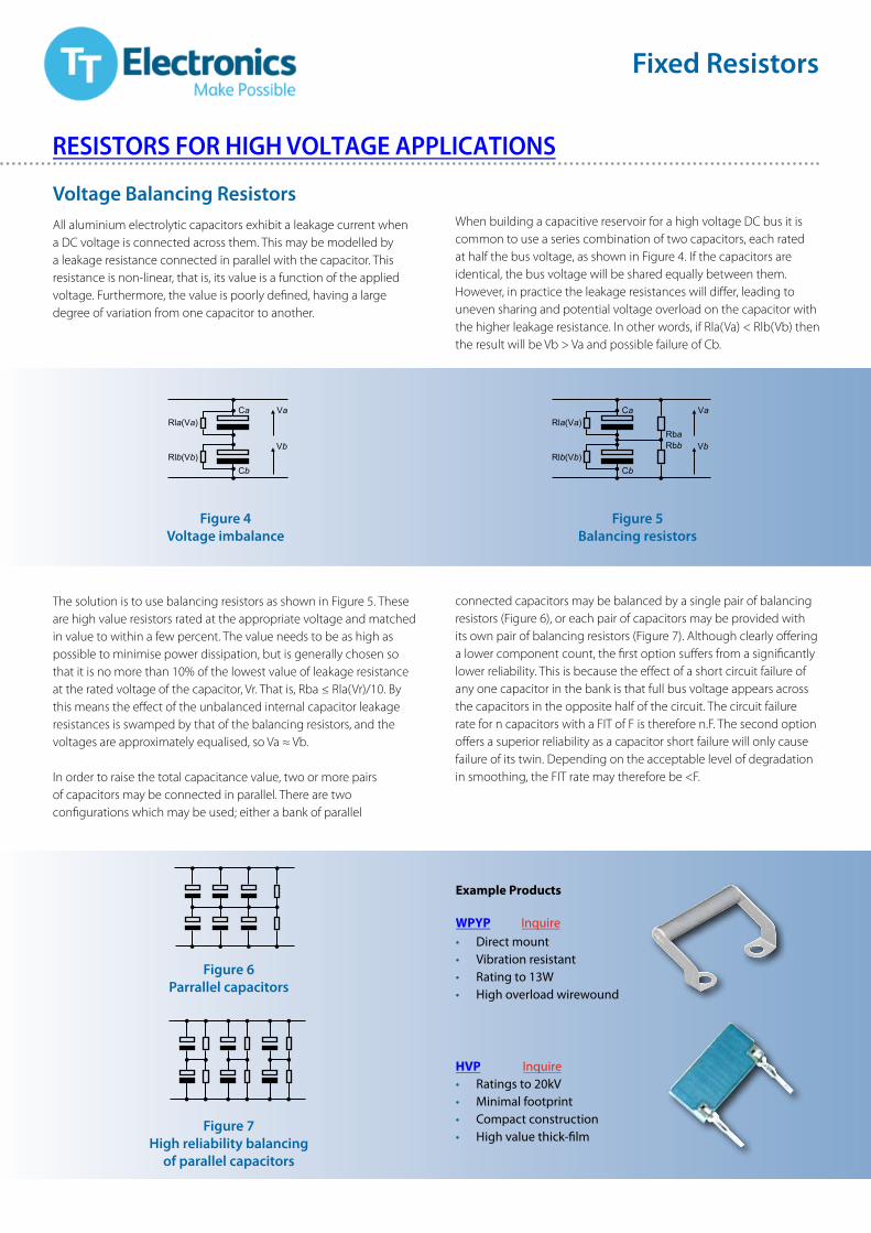
Voltage Balancing ResistorsAll aluminium electrolytic capacitors exhibit a leakage current when a DC voltage is connected across them. This may be modelled by a leakage resistance connected in parallel with the capacitor. This resistance is non-linear, that is, its value is a function of the applied voltage. Furthermore, the value is poorly defined, having a large degree of variation from one capacitor to another.
The solution is to use balancing resistors as shown in Figure 5. These are high value resistors rated at the appropriate voltage and matched in value to within a few percent. The value needs to be as high as possible to minimise power dissipation, but is generally chosen so that it is no more than 10% of the lowest value of leakage resistance at the rated voltage of the capacitor, Vr. That is, Rba ≤ Rla(Vr)/10. By this means the effect of the unbalanced internal capacitor leakage resistances is swamped by that of the balancing resistors, and the voltages are approximately equalised, so Va ≈ Vb.
In order to raise the total capacitance value, two or more pairs of capacitors may be connected in parallel. There are two configurations which may be used; either a bank of parallel
When building a capacitive reservoir for a high voltage DC bus it is common to use a series combination of two capacitors, each rated at half the bus voltage, as shown in Figure 4. If the capacitors are identical, the bus voltage will be shared equally between them. However, in practice the leakage resistances will differ, leading to uneven sharing and potential voltage overload on the capacitor with the higher leakage resistance. In other words, if Rla(Va) < Rlb(Vb) then the result will be Vb > Va and possible failure of Cb.
connected capacitors may be balanced by a single pair of balancing resistors (Figure 6), or each pair of capacitors may be provided with its own pair of balancing resistors (Figure 7). Although clearly offering a lower component count, the first option suffers from a significantly lower reliability. This is because the effect of a short circuit failure of any one capacitor in the bank is that full bus voltage appears across the capacitors in the opposite half of the circuit. The circuit failure rate for n capacitors with a FIT of F is therefore n.F. The second option offers a superior reliability as a capacitor short failure will only cause failure of its twin. Depending on the acceptable level of degradation in smoothing, the FIT rate may therefore be <F.
Cb
Vb
Ca
RbaRbb
Rla(Va)
Rlb(Vb)
Va
Cb
Vb
CaRla(Va)
Rlb(Vb)
Va
Figure 4Voltage imbalance
Figure 6Parrallel capacitors
Figure 7High reliability balancing
of parallel capacitors
Figure 5Balancing resistors
Example Products
WPYP Inquire• Direct mount• Vibration resistant• Rating to 13W• High overload wirewound
HVP Inquire• Ratings to 20kV• Minimal footprint• Compact construction• High value thick-film
RESISTORS FOR HIGH VOLTAGE APPLICATIONS
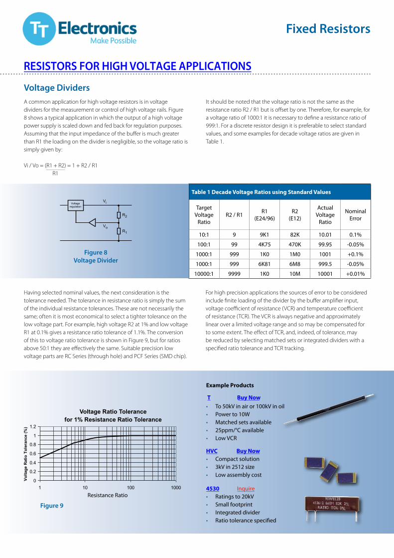
Voltage DividersA common application for high voltage resistors is in voltage dividers for the measurement or control of high voltage rails. Figure 8 shows a typical application in which the output of a high voltage power supply is scaled down and fed back for regulation purposes. Assuming that the input impedance of the buffer is much greater than R1 the loading on the divider is negligible, so the voltage ratio is simply given by:
Vi / Vo = (R1 + R2) = 1 + R2 / R1R1
Having selected nominal values, the next consideration is the tolerance needed. The tolerance in resistance ratio is simply the sum of the individual resistance tolerances. These are not necessarily the same; often it is most economical to select a tighter tolerance on the low voltage part. For example, high voltage R2 at 1% and low voltage R1 at 0.1% gives a resistance ratio tolerance of 1.1%. The conversion of this to voltage ratio tolerance is shown in Figure 9, but for ratios above 50:1 they are effectively the same. Suitable precision low voltage parts are RC Series (through hole) and PCF Series (SMD chip).
For high precision applications the sources of error to be considered include finite loading of the divider by the buffer amplifier input, voltage coefficient of resistance (VCR) and temperature coefficient of resistance (TCR). The VCR is always negative and approximately linear over a limited voltage range and so may be compensated for to some extent. The effect of TCR, and, indeed, of tolerance, may be reduced by selecting matched sets or integrated dividers with a specified ratio tolerance and TCR tracking.
It should be noted that the voltage ratio is not the same as the resistance ratio R2 / R1 but is offset by one. Therefore, for example, for a voltage ratio of 1000:1 it is necessary to define a resistance ratio of 999:1. For a discrete resistor design it is preferable to select standard values, and some examples for decade voltage ratios are given in Table 1.
Fixed Resistors
Voltageregulation
Vi
VoR1
R2
Figure 8Voltage Divider
Figure 9
Resistance Ratio
Table 1 Decade Voltage Ratios using Standard Values
TargetVoltage
RatioR2 / R1 R1
(E24/96)R2
(E12)
ActualVoltage
Ratio
NominalError
10:1 9 9K1 82K 10.01 0.1%
100:1 99 4K75 470K 99.95 -0.05%
1000:1 999 1K0 1M0 1001 +0.1%
1000:1 999 6K81 6M8 999.5 -0.05%
10000:1 9999 1K0 10M 10001 +0.01%
0
0.2
0.4
0.6
0.8
1
1.2
1 10 100 1000
Volta
ge R
atio
Tol
eran
ce (%
)
Voltage Ratio Tolerancefor 1% Resistance Ratio Tolerance
Example Products
T Buy Now• To 50kV in air or 100kV in oil• Power to 10W• Matched sets available• 25ppm/°C available• Low VCR
HVC Buy Now• Compact solution• 3kV in 2512 size• Low assembly cost
4530 Inquire• Ratings to 20kV• Small footprint• Integrated divider• Ratio tolerance specified
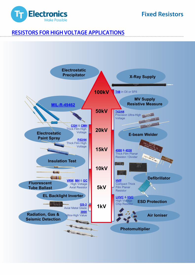
100kV
50kV
20kV
15kV
10kV
5kV
1kV
4500 & 4530 Thick Film Planar Resistor / Divider
T48 in Oil or SF6
VRW, MH & GCHigh Voltage
Axial Resistor
T43/44 Precision Ultra-High Voltage
3800 Ultra-High Value
LHVC & HVCHigh Voltage Chip Resistor
HVPCompact Thick Film Planar Resistor
F43/44Thick Film High
Voltage
CGH & CMH Thick Film High
Voltage
GS-3 Axial Metal Glaze
X-Ray Supply
MV SupplyResistive Measure
E-beam Welder
Defibrillator
ESD Protection
Air Ioniser
Photomultiplier
Radiation, Gas &Seismic Detection
EL Backlight Inverter
FluorescentTube Ballast
ElectrostaticPaint Spray
ElectrostaticPrecipitator
MIL-R-49462
Insulation Test
RESISTORS FOR HIGH VOLTAGE APPLICATIONS
Fixed Resistors
RESISTORS FOR HIGH VOLTAGE APPLICATIONS
General NoteTT electronics reserves the right to make changes in product specification without notice or liability.All information is subject to TT electronics’ own data and is considered accurate at time of going to print.
Note: Circuit diagrams are shown for example only.
TT electronics: leading in fixed resistor technology.
1. HVC up to 1G in development.2. MIL-R-49462 approved version available as CMH
TT electronics companies
Fixed Resistors
© TT electronics plc LIT-AN-HGHVOLTAGE Issue 2
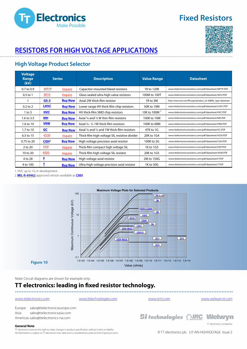
VoltageRange
(kV)Series Description Value Range Datasheet
0.7 to 0.9 WPYP Capacitor-mounted bleed resistors 1R to 120K www.ttelectronicsresistors.com/pdf/datasheet/WPYP.PDF
0.5 to 1 3810 Glass-sealed ultra high value resistors 100M to 100T www.ttelectronicsresistors.com/pdf/datasheet/3810.PDF
1 GS-3 Axial 2W thick-film resistor 1R to 3M http://www.irctt.com/file.aspx?product_id=36&file_type=datasheet
0.2 to 2 LHVC Lower range HV thick-film chip resistors 50K to 10M www.ttelectronicsresistors.com/pdf/datasheet/LHVC.PDF
1 to 3 HVC HV thick-film SMD chip resistors 10K to 100M 1 www.ttelectronicsresistors.com/pdf/datasheet/HVC.PDF
1.6 to 3.5 MH Axial ¼ and ½ W thin-film resistors 100K to 10M www.ttelectronicsresistors.com/pdf/datasheet/MH.PDF
1.6 to 10 VRW Axial ¼ , ½ 1W thick-film resistors 100K to 68M www.ttelectronicsresistors.com/pdf/datasheet/VRW.PDF
1.7 to 10 GC Axial ¼ and ½ and 1W thick-film resistors 47K to 1G www.ttelectronicsresistors.com/pdf/datasheet/GC.PDF
6.5 to 15 4530 Thick-film high voltage SIL resistive divider 20K to 1G4 www.ttelectronicsresistors.com/pdf/datasheet/4530.PDF
0.75 to 20 CGH2 High voltage precision axial resistor 100K to 2G www.ttelectronicsresistors.com/pdf/datasheet/CGH.PDF
2 to 20 HVP Thick-film compact high voltage SIL 1K to 1G5 www.ttelectronicsresistors.com/pdf/datasheet/HVP.PDF
10 to 20 4500 Thick-film high voltage SIL resistor 20K to 1G5 www.ttelectronicsresistors.com/pdf/datasheet/4500.PDF
4 to 28 F High voltage axial resistor 2M to 150G www.ttelectronicsresistors.com/pdf/datasheet/F.PDF
4 to 100 T Ultra-high voltage precision axial resistor 1K to 50G www.ttelectronicsresistors.com/pdf/datasheet/T.PDF
High Voltage Product Selector
0.1
1
10
100
1.E+03 1.E+04 1.E+05 1.E+06 1.E+07 1.E+08 1.E+09 1.E+10 1.E+11 1.E+12 1.E+13 1.E+14
Value (ohms)
Max
imum
Con
tinuo
us V
olta
ge (k
V) . T48
HVP5 / CGH5T44
CGH3GC70
CGH2
CGH1VRW/MH37
CGH1/2
VRW/MH25
3810
3811 3812
T48 in oil
T43
Maximum Voltage Plots for Selected Products
Figure 10
Europe: [email protected]: [email protected]: [email protected]
www.ttelectronics.com www.bitechnologies.com www.irctt.com www.welwyn-tt.com
Buy Now
Inquire
Buy Now
Inquire
Buy Now
Buy Now
Buy Now
Buy Now
Buy Now
Inquire
Inquire
Inquire
Buy Now
Buy Now