lawn tractor series 0dl.owneriq.net/6/6167d8e2-7941-f604-2d85-cd7b29ae4dd7.pdf1. extinguish all...
TRANSCRIPT

Safety Instructions & Operator's Manual for
NOTE: Specifications are correct at time of printing and are subject to change without notice. * Actual sustained engine power will likely be lower due to operating limitations and environmental factors. Please refer to ‘Engine Power Rating Information’ forfurther details.
Manual No. 7102174 (I.R. 12/11/2007)TP 100-5314-IR-TC-N
LAWN TRACTORSERIES 0Models
LT195420 (7800206)LT23460 (7800207)LT24520 (7800212)
SLT23460 (7800342)SLT24520 (7800343)CLT23460 (7800344)CLT24520 (7800345)

Thank you for purchasing this quality-built Snapper product. We are pleased that you’ve placed your confidence in the Snapperbrand. When operated and maintained according to the instructions in this manual, your Snapper mower will provide manyyears of dependable service.
This manual contains safety information to make you aware of the hazards and risks associated with mowers and how toavoid them. Because Snapper does not necessarily know all the applications this mower could be used for, it is important thatyou read and understand these instructions. Keep this manual near the mower for convenient reference.
This mower requires final assembly before use. Refer to the Assembly section of this manual for instructions on finalassembly procedures. Follow the instructions completely.
Where to Find UsYou never have to look far to find Briggs & Stratton support and service for your mower. Consult your Yellow Pages. There areover 30,000 Briggs & Stratton authorized service dealers worldwide who provide quality service. You can also contact SnapperCustomer Service at 1-800-317-7833, or on the Internet at www.snapper.com.
Mower
Model Number _____________________________________
Serial Number _____________________________________
Engine
Model _____________________________________
Type _____________________________________
Trim _____________________________________
Date Purchased
It is very important that you register your purchase with Snapper to ensure warranty coverage. Please mail your productregistration card to:
Snapper at P.O. Box 777, McDonough, Georgia 30253.
Or you may register online at www.snapper.com.
Briggs & Stratton Yard Power Products GroupCopyright © 2007, Briggs & Stratton Corporation
Milwaukee, WI, USA. All Rights Reserved.
SNAPPER is a trademark of Simplicity Manufacturing, Inc.Port Washington, WI, USA.

Table of Contents
Operator Safety . . . . . . . . . . . . . . . . . . . . . . . . . . . . . . . . . . 2Important Operator Safety Instructions . . . . . . . . . . . . . . . . . . . . . . . . . . . . . 2International Pictorials . . . . . . . . . . . . . . . . . . . . . . . . . . . . . . . . . . . . . . . . . . 5
Assembly . . . . . . . . . . . . . . . . . . . . . . . . . . . . . . . . . . . . . . 6Parts Bag - Contents . . . . . . . . . . . . . . . . . . . . . . . . . . . . . . . . . . . . . . . . . . . 6Installing the Seat . . . . . . . . . . . . . . . . . . . . . . . . . . . . . . . . . . . . . . . . . . . . . 7Assembling the Steering Wheel . . . . . . . . . . . . . . . . . . . . . . . . . . . . . . . . . . . 7Maintenance Free Battery. . . . . . . . . . . . . . . . . . . . . . . . . . . . . . . . . . . . . . . . 8IMPORTANT! Before You Start Mowing . . . . . . . . . . . . . . . . . . . . . . . . . . . . 9
Features and Controls. . . . . . . . . . . . . . . . . . . . . . . . . . . . . . 11
Operation . . . . . . . . . . . . . . . . . . . . . . . . . . . . . . . . . . . . . . 12Attachments. . . . . . . . . . . . . . . . . . . . . . . . . . . . . . . . . . . . . . . . . . . . . . . . . . 12Using Controls . . . . . . . . . . . . . . . . . . . . . . . . . . . . . . . . . . . . . . . . . . . . . . . . 12Driving and Stopping the Unit . . . . . . . . . . . . . . . . . . . . . . . . . . . . . . . . . . . . 13Mowing . . . . . . . . . . . . . . . . . . . . . . . . . . . . . . . . . . . . . . . . . . . . . . . . . . . . . 16Engine Operation . . . . . . . . . . . . . . . . . . . . . . . . . . . . . . . . . . . . . . . . . . . . . . 18Tips . . . . . . . . . . . . . . . . . . . . . . . . . . . . . . . . . . . . . . . . . . . . . . . . . . . . . . . . 19
Maintenance . . . . . . . . . . . . . . . . . . . . . . . . . . . . . . . . . . . . 20Maintenance Schedule . . . . . . . . . . . . . . . . . . . . . . . . . . . . . . . . . . . . . . . . . . 20General Recommendations . . . . . . . . . . . . . . . . . . . . . . . . . . . . . . . . . . . . . . 21Inspection . . . . . . . . . . . . . . . . . . . . . . . . . . . . . . . . . . . . . . . . . . . . . . . . . . . 21Adjustments. . . . . . . . . . . . . . . . . . . . . . . . . . . . . . . . . . . . . . . . . . . . . . . . . . 22Maintenance Free Battery. . . . . . . . . . . . . . . . . . . . . . . . . . . . . . . . . . . . . . . . 26Lubrication. . . . . . . . . . . . . . . . . . . . . . . . . . . . . . . . . . . . . . . . . . . . . . . . . . . 27Mower Deck Maintenance . . . . . . . . . . . . . . . . . . . . . . . . . . . . . . . . . . . . . . . 28Misc . . . . . . . . . . . . . . . . . . . . . . . . . . . . . . . . . . . . . . . . . . . . . . . . . . . . . . . . 38Storage . . . . . . . . . . . . . . . . . . . . . . . . . . . . . . . . . . . . . . . . . . . . . . . . . . . . . 39
Troubleshooting . . . . . . . . . . . . . . . . . . . . . . . . . . . . . . . . . . 40
Specifications . . . . . . . . . . . . . . . . . . . . . . . . . . . . . . . . . . . 42
Slope Guide . . . . . . . . . . . . . . . . . . . . . . . . . . . . . . . . . . . . 43
Warranties . . . . . . . . . . . . . . . . . . . . . . . . . . . . . . . . . . . . . 45General Warranty . . . . . . . . . . . . . . . . . . . . . . . . . . . . . . . . . . . . . . . . . . . . . . 45
1
English EspañolEnglish
WARNINGBattery posts, terminals and related accessories containlead and lead compounds, chemicals known to the State ofCalifornia to cause cancer and birth defects or otherreproductive harm. Wash hands after handling.
! ! WARNINGEngine exhaust, some of its constituents, and certainvehicle components contain or emit chemicals known tothe State of California to cause cancer or other reproductiveharm.
! !

English
2 www.snapper.com
! !
WARNING: This powerful cutting machine is capable of amputating hands and feet and can throw objectsthat can cause injury and damage! Failure to comply with the following SAFETY instructions could result inserious injury or death to the operator or other persons. The owner of the machine must understand theseinstructions and must allow only persons who understand these instructions to operate machine. Eachperson operating the machine must be of sound mind and body and must not be under the influence of anysubstance, which might impair vision, dexterity or judgment. If you have any questions pertaining to yourmachine which your dealer cannot answer to your satisfaction, call or write the Customer ServiceDepartment at SNAPPER, McDonough, Georgia 30253. Phone: (1-800-317-7833).
Protection for ChildrenTragic accidents can occur if the operator is not alert to thepresence of children. Children are often attracted to themachine and the mowing activity. Children who have beengiven rides in the past may suddenly appear in the mowingarea for another ride and be run over or backed over by themachine. Never assume that children will remain where youlast saw them.1. KEEP children out of the mowing area and under thewatchful care of a responsible adult other than the operator. 2. DO NOT allow children in yard when machine is operated(even with the blade OFF). 3. DO NOT allow children or others to ride on machine,attachments or towed equipment (even with the bladesOFF). They may fall and be seriously injured. 4. DO NOT allow pre-teenage children to operate machine.5. ALLOW only responsible adults & teenagers with maturejudgment under close adult supervision to operate machine. 6. DO NOT operate blades in reverse. STOP BLADES. LOOKand SEE behind and down for children, pets and hazardsbefore and while backing.7. USE EXTRA CARE when approaching blind corners,shrubs, trees, or other objects that may obscure vision.
Protection against TipoversSlopes are a major factor related to loss-of-control and tip-over accidents, which can result in severe injury or death.All slopes require extra CAUTION. If you cannot back up theslope or if you feel uneasy on the slope, DO NOT mow it.Use extra care with grass catchers or other attachments;these affect the handling and the stability of the machine.Refer to the Slope Guide at the end of this manual.1. DO NOT operate machine on slopes exceeding 15degrees (27% grade).2. Exercise EXTREME CAUTION on slopes above 10degrees (18% grade). Turn blades OFF when travelinguphill. Use a slow speed and avoid sudden or sharp turns. 3. DO NOT operate machine back and forth across face ofslopes. Operate up and down. Practice on slopes withblades off.4. AVOID starting, stopping or turning on slopes. Ifmachine stops going uphill or tires lose traction, turnblades OFF and back slowly straight down the slope.5. STAY ALERT for holes and other hidden hazards. Tallgrass can hide obstacles. Keep away from ditches,washouts, culverts, fences and protruding objects.
Protection against Tipovers(Continued From Previous Column)6. KEEP A SAFE DISTANCE (at least 3 feet) away from edgeof ditches and other drop offs. The machine could turn overif an edge caves in. 7. Always begin forward motion slowly and with caution.8. Use weights or a weighted load carrier in accordancewith instructions supplied with a grass catcher. DO NOToperate machine on slopes exceeding 10 degrees (18%grade) when equipped with grass catcher.9. DO NOT put your foot on the ground to try to stabilizethe machine. 10. DO NOT operate machine on wet grass. Reducedtraction could cause sliding. 11. Choose a low enough speed setting so that you will nothave to stop or shift on a slope. Tires may lose traction onslopes even though the brakes are functioning properly.12. DO NOT operate machine under any condition wheretraction, steering or stability is doubtful.13. Always keep the machine in gear when going downslopes. DO NOT shift to neutral (or actuate hydro rollrelease) and coast downhill.
Preparation1. Read, understand, and follow instructions and warningsin this manual and on the machine, engine andattachments. Know the controls and the proper use of themachine before starting.2. Only mature, responsible persons shall operate themachine and only after proper instruction. 3. Data indicates that operators age 60 and above, areinvolved in a large percentage of mower-related injuries.These operators should evaluate their ability to operate themower safely enough to protect themselves and othersfrom serious injury.4. Handle fuel with extra care. Fuels are flammable andvapors are explosive. Use only an approved fuel container.DO NOT remove fuel cap or add fuel with engine running.Add fuel outdoors only with engine stopped and cool. Cleanspilled fuel from machine. DO NOT smoke. 5. Practice operation of machine with BLADES OFF to learncontrols and develop skills.6. Check the area to be mowed and remove all objects suchas toys, wire, rocks, limbs and other objects that couldcause injury if thrown by blade or interfere with mowing.
Important Operator Safety Instructions

English
3
! !Protection against Tipovers(Continued From Previous Column)7. Keep people and pets out of mowing area. ImmediatelySTOP blades, STOP engine, and STOP machine if anyoneenters the area.8. Check shields, deflectors, switches, blade controls andother safety devices frequently for proper operation andlocation. 9. Make sure all safety decals are clearly legible. Replace ifdamaged. 10. Protect yourself when mowing and wear safety glasses,a dust mask, long pants and substantial footwear.11. Know how to STOP blades and engine quickly inpreparation for emergencies. 12. Use extra care when loading or unloading the machineinto a trailer or truck. 13. Check grass catcher components frequently for signs ofwear or deterioration and replace as needed to preventinjury from thrown objects going through weak or wornspots.
Safe Handling of GasolineTo avoid personal injury or property damage, use extremecare in handling gasoline. Gasoline is extremely flammableand the vapors are explosive.1. Extinguish all cigarettes, cigars, pipes and other sourcesof ignition.2. Use only an approved fuel container.3. DO NOT remove fuel cap or add fuel with the enginerunning. Allow the engine to cool before refueling.4. DO NOT refuel the machine indoors.5. DO NOT store the machine or fuel container inside wherethere is an open flame, spark or pilot light such as on awater heater or other appliances.6. DO NOT fill fuel containers inside a vehicle or on a truckor trailer bed with a plastic liner. Always place thecontainers on the ground away from the vehicle beforefilling.7. Remove gas-powered equipment from the vehicle ortrailer and refuel it on the ground. If this is not possible,then refuel equipment using a portable container, ratherthan a gasoline dispenser nozzle.8. DO NOT start gas powered equipment in enclosedvehicles or trailers.9. Keep the nozzle in contact with the rim of the fuel tank orcontainer opening at all times until fueling is complete. DONOT use a nozzle lock-open device10. If fuel is spilled on clothing, change clothingimmediately.11. Never overfill a fuel tank. Replace fuel cap and tightensecurely.
Operation1. Mount and dismount machine from left side. Keep clearof discharge opening at all times.2. Start engine from operator’s seat, if possible. Make sureblades are OFF and parking brake is set. 3. DO NOT leave machine with engine running. STOPengine, STOP blades, SET brake, and Remove key beforeleaving operators position of any reason.4. DO NOT operate machine unless properly seated withfeet on feet rests or pedal(s).5. STOP BLADES and ENGINE and make sure blades havestopped before removing grass catcher or uncloggingmower to prevent loss of fingers or hand. 6. Blades must be OFF except when cutting grass. Setblades in highest position when mowing over roughground. 7. Keep hands and feet away from rotating bladesunderneath deck. DO NOT place foot on ground whileBLADES are ON or machine is in motion. 8. DO NOT operate machine without entire grass catcher orguards in place and working. DO NOT point discharge atpeople, passing cars, windows or doors. 9. Slow down before turning. 10. Watch out for traffic when near or crossing roadways.11. STOP engine immediately after striking an obstruction.Inspect machine and repair damage before resumingoperation. 12. Operate machine only in daylight or with good artificiallight. 13. Move joystick (if equipped) SLOWLY to maintaincontrol during speed and directional changes. 14. Exercise CAUTION when pulling loads. Limit loads tothose you can safely control and attach loads to hitch plateas specified with SNAPPER attachment instructions.15. On slopes, the weight of the towed equipment maycause loss of traction and loss of control. When towing,travel slowly and allow extra distance to stop.16. DO NOT operate engine in enclosed areas. Engineexhaust gases contain carbon monoxide, a deadly poison. 17. DO NOT discharge material against a wall orobstruction. Material may ricochet back towards theoperator.18. Only use accessories approved by the manufacturer.See manufacturer’s instructions for proper operation andinstallation of accessories.
Important Operator Safety Instructions (Continued)

English
4 www.snapper.com
! !Towing1. Tow only with a machine that has a hitch designed fortowing. DO NOT attach towed equipment except at the hitchpoint.2. Follow the manufacturer’s recommendation for weightlimits for towed equipment and towing on slopes.3. DO NOT allow children or others on towed equipment.4. On slopes, the weight of the towed equipment may causeloss of traction and loss of control.5. Travel slowly and allow extra distance to stop.
Maintenance1. DO NOT store machine or fuel container inside wherefumes may reach an open flame, spark or pilot light such asin a water heater, furnace, clothes dryer or other gasappliance. Allow engine to cool before storing machine inan enclosure. Store fuel container out of the reach ofchildren in a well ventilated, unoccupied building. 2. Keep engine free of grass, leaves or excess grease toreduce fire hazard and engine overheating. 3. When draining fuel tank, drain fuel into an approvedcontainer outdoors and away from open flame. 4. Check brakes frequently; adjust, repair or replace asneeded.5. Keep all bolts, nuts and screws properly tight. Check thatall cotter pins are in proper position.
Maintenance(Continued From Previous Column)6. Always provide adequate ventilation when runningengine. Exhaust gases contain carbon monoxide, anodorless and deadly poison. 7. Disconnect negative (black) cable from battery beforeperforming maintenance or service. Cranking engine couldcause injury. 8. DO NOT work under machine without safety blocks. 9. Service engine and make adjustments only when engineis stopped. Remove spark plug wire(s) from spark plug(s)and secure wire(s) away from spark plug(s). 10. DO NOT change engine governor speed settings oroverspeed engine. 11. Lubricate machine at intervals specified in manual toprevent controls from binding. 12. Mower blades are sharp and can cut. Wrap the bladesor wear heavy leather gloves and use CAUTION whenhandling them. 13. DO NOT test for spark by grounding spark plug next tospark plug hole; spark plug could ignite gas exiting engine.14. Have machine serviced by an authorized SNAPPERdealer at least once a year and have the dealer install anynew safety devices. 15. Maintain or replace safety and instruction labels asnecessary.16. Use only genuine SNAPPER replacement parts toassure that original standards are maintained.
Important Operator Safety Instructions (Continued)

International PictorialsIMPORTANT: Some of the following pictorials are located on your unit or on literature supplied with the product. Before youoperate the unit, learn and understand the purpose for each pictorial.
Figure 1: Safety warning pictorials
A B C D E
G H
F
I JK
L M N P
max 15°
A - WarningB - Shield Eyes. Explosive Gases Can
Cause Blindness Or Injury.C - No Sparks, Flames or Smoking.D - Sulphuric Acid Can Cause Blindness
Or Severe BurnsE - Flush Eyes Immediately With Water.
Get Medical Help Fast.F - IMPORTANT: Read Owner’s Manual
Before Operating This Machine.
G - WARNING: Thrown Objects. KeepBystanders Away. Read UserInstructions Before Operating ThisMachine.
H - WARNING: Do Not Use ThisMachine On Slopes Greater Than 15Degrees.
I - DANGER: Keep People, EspeciallyChildren, Away From Unit.
J - DANGER: No Step.
K - DANGER: Keep Feet And HandsAway From Rotating Blade.
L- DANGER: Keep Hands Away FromRotating Blade.
M - DANGER: Disconnect Spark PlugWire Before Servicing Unit.
N - WARNING: Hot Surface.O - WARNING: Use Caution When
Connecting Or DisconnectingAccessories.
P - WARNING: Crushed Fingers.
A - Engine startB - LightsC - Engine offD - Engine onE - Brake
F - Parking brakeG - ClutchH - SlowI - FastJ - Choke
K - OilL - Blade rotation controlM - RaiseN - Fuel
A B C D E G HF
I J K L M N
max± 90N max± 150N
O
Figure 2: Control and operating pictorials
English
5

AssemblyRead and follow the assembly and adjustmentinstructions for your mower. All fasteners are in the parts bag. Do not discardany parts or material until the unit is assembled.
NOTE: In this instruction book, left and right describe thelocation of a part with the operator on the seat.
WARNING: Before doing any assembly ormaintenance to the mower, remove the wire fromthe spark plug.
6 www.snapper.com
English
Parts Bag - ContentsThe fasteners and other loose parts are shown below. The fastenersare shown full size. The quantity is shown in brackets ( ).
Figure 3: Parts bag components
A - (2) Carriage boltB - (2) Wing nutC - (1) Bolt
D - (1) WasherE - (2) KnobF - (2) Washer
G - (1) Keys & ringH - (1) Terminal cover
A B C
D
EG
H
F

Installing the Seat
How to Install the Seat1. Carefully remove the plastic bag from the seat. Use the
fasteners shown below to install the seat. The fastenersare shown at full size.
Figure 4: Seat parts
A - Wing bolt (Also see ‘E’ in Figure 3)B - Washer (Also see ‘F’ in Figure 3)
NOTE: Fasteners may be attached to seat for shippingpurposes, if so remove fasteners before proceeding.
2. Align the holes in the seat hinge to the holes in theseat (Figure 5). Fasten the seat to the seat hinge withthe fasteners as shown.
3. Check the operating position of the seat. If the seatneeds to be adjusted, loosen the two wing bolts. Slidethe seat forward or backward along the seat adjustingholes as shown. Tighten the wing bolts (A).
Figure 5: Seat
A - Wing boltB - WasherC - Seat adjusting holeD - Seat hingeE - Seat
Assembling the Steering Wheel
How to Assemble the Steering WheelTools Required: 3/8" Socket WrenchAttach the steering wheel as follows:
Figure 6: Steering wheel parts
A - Screw (Also see ‘C’ in Figure 3)B - Washer (Also see ‘D’ in Figure 3)
1. Make sure the front wheels point forward.2. Slide the bellows over the steering post
(Figure 7).NOTE: Before attachment of the steering wheel, makesure that the front wheels point forward and arestraight. For proper alignment of the steering wheel,see Figure 7.
3. Slide the steering wheel onto the steering post.4. Use the fasteners shown above to secure the steering
wheel. The fasteners are shown at full size. Tighten thescrew until snug and then add 1/4 turn. DO NOT overtighten.
5. Attach the cover to the steering wheel.6. Some models have an optional decal in the parts bag.
Attach the decal to the center of the steering wheel asshown.
7
English
A B
A
B
BC
D
E
A
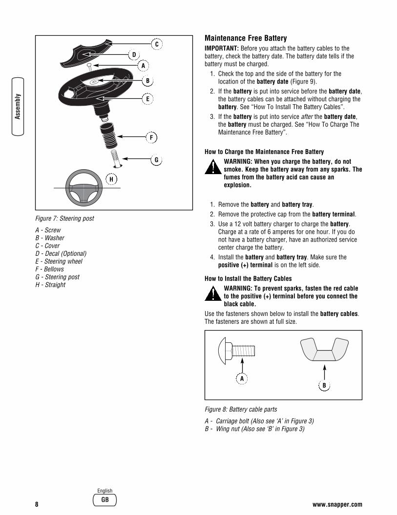
Figure 7: Steering post
A - ScrewB - WasherC - CoverD - Decal (Optional)E - Steering wheelF - BellowsG - Steering postH - Straight
Maintenance Free BatteryIMPORTANT: Before you attach the battery cables to thebattery, check the battery date. The battery date tells if thebattery must be charged.
1. Check the top and the side of the battery for thelocation of the battery date (Figure 9).
2. If the battery is put into service before the battery date,the battery cables can be attached without charging thebattery. See “How To Install The Battery Cables”.
3. If the battery is put into service after the battery date,the battery must be charged. See “How To Charge TheMaintenance Free Battery”.
How to Charge the Maintenance Free BatteryWARNING: When you charge the battery, do notsmoke. Keep the battery away from any sparks. Thefumes from the battery acid can cause anexplosion.
1. Remove the battery and battery tray.2. Remove the protective cap from the battery terminal.3. Use a 12 volt battery charger to charge the battery.
Charge at a rate of 6 amperes for one hour. If you donot have a battery charger, have an authorized servicecenter charge the battery.
4. Install the battery and battery tray. Make sure thepositive (+) terminal is on the left side.
How to Install the Battery CablesWARNING: To prevent sparks, fasten the red cableto the positive (+) terminal before you connect theblack cable.
Use the fasteners shown below to install the battery cables.The fasteners are shown at full size.
Figure 8: Battery cable parts
A - Carriage bolt (Also see ‘A’ in Figure 3)B - Wing nut (Also see ‘B’ in Figure 3)
8 www.snapper.com
English
D
A
B
E
C
H
G
F
AB

1. Remove the protective cap from the battery terminal. 2. Fasten the red cable and terminal cover (if equipped)
to the positive (+) terminal with the fasteners asshown (Figure 9).
3. Fasten the black cable to the negative (-) terminal withthe fasteners as shown.
Figure 9: Battery
A - Carriage boltB - Wing nutC - Black cableD - Positive (+) terminalE - Red cableF - BatteryG - Battery trayH - Terminal cover (Also see ‘H’ in Figure 3)
IMPORTANT! Before You Start Mowing• Check the engine oil.• Fill the fuel tank with gasoline.• Check the air pressure of the tires.• Check the level of the mower housing.• Make sure the battery cables are attached.• Make sure the wire is attached to the spark plug.
WARNING: Before doing any assembly ormaintenance to the mower, remove the wire fromthe spark plug.
NOTE: In this instruction book, left and right describe thelocation of a part with the operator on the seat.
9
English
H
AE
A
B
DC
G
F

How to Prepare the EngineNOTE: The engine was shipped from the factory filled withoil. Check the level of the oil. Add oil as needed. NOTE: The operation of a new engine will sometimes resultin a slight amount of smoke. This smoke is caused by paintor oil on or around the muffler. This is normal and onlyexpected during initial operation. A separate engine manual is also included with the unit. Seethis engine manual for the manufacturer’s instructions forthe type of gasoline and oil to use. Before you use the unit,read the information on safety, operation, maintenance, andstorage.
WARNING: Follow the engine manufacturer’sinstructions for the type of gasoline and oil to use.Always use a safety gasoline container. Do notsmoke when adding gasoline to the engine. Wheninside an enclosure, do not fill with gasoline.Before you add gasoline, stop the engine. Let theengine cool for several minutes.
IMPORTANT: This unit is equipped with an internalcombustion engine and must not be used on or near anyunimproved forest-covered, brush-covered or grass-coveredland unless the engine’s exhaust system is equipped with aspark arrester meeting applicable local or state laws (if any).If a spark arrester is used, it must be maintained in effectiveworking order by the operator. In the State of California the above is required by law(Section 4442 of the California Public Resources Code).Other states may have similar laws. Federal laws apply onfederal lands. See an Authorized Service Center for a sparkarrester for the muffler. In some areas, local law requires the use of a resistor sparkplug to control the ignition signals. See an AuthorizedService Center for a resistor spark plug for the engine. NOTE: Actual sustained horsepower will likely be lower dueto operating limitations and environmental factors.
Check the TiresNOTE: The tires may be over inflated for shipment. Check the air pressure in the tires. Tires with too much airpressure will cause the unit to ride rough. Also, the wrongair pressure will keep the mower housing from cutting level.Recommended air pressure is 14 PSI (1 BAR).
Check the Level of the Mower DeckMake sure the level of cut is still correct. After you mow ashort distance, look at the area that was cut. If the mowerdeck does not cut level, see the instructions on “How ToLevel The Mower Deck” in the Maintenance section of thisinstruction book.
10 www.snapper.com
English

Features and Controls
A - Throttle Control / Choke Control Levers — Throttlecontrol increases or decreases the speed of the engine.Choke control engages the choke to start a cold engine.(Note: The choke control lever is incorporated into thethrottle control lever on 42” models.)
B - Steering Wheel (Removed for clarity) — Steers the unit.
C - Brake Pedal — Quickly stops the unit.
D - Deck Lift Lever — Changes the height of cut.
E - PTO Switch (46 & 52” Models) — Starts and stops therotation of the blades.
F - Blade Rotation Control (42” Models) — Starts and stopsthe rotation of the blades.
G - Cruise Control — Locks ground speed in forward.
H - Reverse Mowing Option (RMO) — Allows engaging ofmowing deck while traveling in reverse.
I - Ignition Switch — Starts and stops the engine. (Note: Theheadlight switch is incorporated into the ignition switch.)
J - Parking Brake Lever — Engages the brake when youleave the unit.
K - Speed Control Pedal — Changes the speed and thedirection of the unit.
L - Automatic Drive Disconnect (not shown, located behindthe unit) — Disengages the transmission.
11
English
I
J
F
A
C
K
E
D
G
H
B

Operation
AttachmentsThis unit can use many different attachments.For all pull-behind attachments or trailers, the maximumgross weight is 250 pounds. Gross weight is the weight ofthe attachment or trailer and any load that might be on or init. Do not operate on a slope that is greater than 10 degreeswhen using a pull-behind attachment or trailer. We haveincluded a slope guide in this book to help you determine theslope on which you will be operating your unit. Never allowsomeone to stand or ride on or in an attachment or trailer.
Using Controls
How to Use the Throttle ControlUse the throttle control to increase or decrease the speed ofthe engine. CAUTION: Always operate the engine with the throttlecontrol in the FAST position. If the engine runs for severalminutes at slower than the FAST position, the engine andtransmission will overheat and can be damaged.
1. The FAST position is marked with a detent. For normaloperation and when using a grass bagger, move thethrottle control to the FAST position. For maximumcharging of the battery and for a cooler running engineand transmission, operate the engine in the FASTposition.
2. For transport and to tow pull behind attachments,control the ground speed with the speed control pedal.
3. The engine governor is set at the factory for maximumperformance. Do not adjust the governor to increasethe speed of the engine.
How to Engage the Blades (42” Models)The blade rotation control is located above the steeringwheel (Figure 10). Use the blade rotation control to engagethe blades.
Figure 10: Blade rotation control (42” Models Only)
A - DISENGAGE positionB - Blade rotation control ENGAGE position
1. Before you start the engine, make sure the bladerotation control is in the DISENGAGE position.
2. Move the blade rotation control to the ENGAGEposition to rotate the blades. NOTE: If the engine stops when you engage the blades,the seat switch is not activated. Make sure you sit inthe middle of the seat. Also, make sure the wire isconnected to the seat switch.
3. Move the blade rotation control to the DISENGAGEposition to stop the blades. Before you leave theoperator’s position, make sure the blades have stoppedrotating.
4. Before you ride the unit across a sidewalk or a road,move the blade rotation control to the DISENGAGEposition.
WARNING: Always keep your hands and feet awayfrom the blade, deflector opening, and the mowerhousing when the engine runs.
12 www.snapper.com
English
A
B

How to Engage the Blades (46 & 52” models)The PTO switch is above and to the right of the steeringwheel (Figure 11). Use the PTO switch to engage the blades.
Figure 11: PTO switch (46 & 52” models only)A - PTO switch (shown in the DISENGAGE position)
1. Before you start the engine, make sure the PTO switchis pushed down in the DISENGAGE position.
2. Pull the PTO switch up to the ENGAGE position torotate the blades. NOTE: If the engine stops when you engage the blades,the seat switch is not activated. Make sure you sit inthe middle of the seat. Also, make sure the wire isconnected to the seat switch.
3. Push the PTO switch down to the DISENGAGE positionto stop the blades. Before you leave the operator’sposition, make sure the blades have stopped rotating.
4. Before you ride the unit across a sidewalk or a road,push the PTO switch down to the DISENGAGE position.
WARNING: Always keep your hands and feet awayfrom the blade, deflector opening, and the mowerhousing when the engine runs.
How to Use the Speed Control PedalThe drive system uses a Hydrostatic Automatic Drivetransmission. The Hydrostatic transmission is very easy tooperate. This type of drive system does not require a shiftlever or a clutch pedal.The speed and direction of travel is controlled by a singlespeed control pedal operated with your right foot. Do notuse the left brake pedal in normal operation. Only use the leftbrake pedal to quickly stop in an emergency.
Driving and Stopping the Unit
How to Drive Forward1. The automatic drive disconnect must be in the DRIVE
position (Figure 14).2. Slowly release your left foot from the brake pedal.3. Move the throttle control to the FAST position.4. Slowly push the speed control pedal forward to the
desired speed (Figure 12).5. To increase forward speed, slowly move the speed
control pedal forward. To reduce forward speed, slowlyrelease the speed control pedal until the unit slows tothe desired speed.
Figure 12: Speed control operation
A - ReverseB - NeutralC - ForwardD - Forward movementE - Reverse movementF - Speed control pedal
13
English
A
E D
F
7101936 A B C

How to Use the Cruise ControlTo engage the cruise control:
1. Slowly push the speed control pedal forward to thedesired speed (Figure 12).
2. Pull up on the cruise control knob (Figure 13). Releasethe speed control pedal. The unit should continuetraveling forward at the desired speed.NOTE: The cruise control only operates in forwardspeeds.
To disengage the cruise control:1. Push the speed control pedal (Figure 12), OR2. Push the brake pedal.
WARNING: Do not engage the cruise control whendriving on slopes, or when people or animals are inthe vicinity.
Figure 13: Cruise control
A - Cruise Control knob
How to Drive in Reverse1. Look to the rear.2. Slowly push the speed control pedal to the REVERSE
position.
How to Change DirectionCAUTION: To change directions, do not use the left brakepedal. Use only the speed control pedal.
1. Slowly remove your foot from the speed control pedal.The speed control pedal will automatically return to theNEUTRAL position.
2. When the unit stops, slowly move the speed controlpedal to the desired direction.
Speed Control Pedal PositionsThe forward speed is controlled by the position of the speedcontrol pedal. The following chart provides functions alongwith the pedal positions. Always operate the engine with thethrottle control in the FAST position.
How to Disconnect the TransmissionTo push the unit, use the automatic drive disconnect torelease the transmission. The automatic drive disconnect islocated on the right rear of the unit.
1. The engine must be off.2. Pull out and lock the automatic drive disconnect in the
PUSH position (Figure 13). The transmission is nowreleased and the unit can be pushed.NOTE: In cold weather, the heavy viscosity oil in thetransmission will make the unit difficult to push.
3. To engage the transmission, unlock and push in theautomatic drive disconnect. The transmission is nowconnected and ready to operate.
Function Pedal Positon Throttle Position
Trimming Snow Thrower 1/3 Fast Throttle
Bagging Grass 1/3 to 1/2
Normal Mowing 1/2 to 2/3
Easy MowingSnow Blade 1/2 to 3/4
Transport FULL
Pull BehindAttachments 1/3 to 1/2
14 www.snapper.com
English
A

Figure 13: Automatic drive disconnect
A - Automatic drive disconnect DRIVE positionB - Automatic drive disconnect PUSH positionC - Automatic drive disconnect
How to Set the Parking Brake1. Completely push the brake pedal forward. 2. Lift the parking brake lever (Figure 14). 3. Remove your foot from the brake pedal and then
release the parking brake lever. Make sure the parkingbrake will hold the unit.
4. To release the parking brake, completely push the brakepedal forward. The parking brake will automaticallyrelease.
WARNING: Before you leave the operator’s position,move the speed control pedal to the neutral (N)position. Set the parking brake. Move the bladerotation control to the DISENGAGE position. Stop theengine and remove the ignition key.
Figure 14: Parking brake
A - Brake pedalB - Parking brake lever
How to Change the Cutting HeightTo change the cutting height, raise or lower the deck iftlever as follows:
1. Move the deck lift lever forward to lower the mowerhousing and back to raise the mower deck (Figure 15).
2. When you ride on a sidewalk or road, move the deck liftlever to the highest position and disengage the blades(Figures 10, 11).
Figure 15: Lift control
A - Deck lift lever
How to Stop the Unit1. Slowly remove your foot from the speed control pedal.
The speed control pedal will automatically return to theNEUTRAL position and the unit will stop.
2. Move the blade rotation control to the DISENGAGEposition.
3. Set the parking brake.WARNING: Make sure the parking brake will holdthe unit.
4. Move the throttle control to the SLOW position.5. To stop the engine, turn the ignition key to the OFF
position. Remove the key.
15
English
C
A
A
7101935
A B
B

How to Transport the UnitTo transport the unit, follow the steps below.
1. Disengage the blades.2. Raise the deck lift lever to the highest position.3. Move the throttle control to the FAST position.4. Slowly push the speed control pedal forward to the
desired speed.
Mowing
How to Operate the Mower DeckWARNING: The deflector is a safety device. Do notremove the deflector. The deflector forces thedischarged material toward the ground. Alwayskeep the deflector in the down position. If thedeflector is damaged, replace the deflector with anoriginal equipment part from an authorized servicecenter.
1. Start the engine.2. Release the parking brake.3. Move the deck lift lever to a height of cut position. In
high or thick grass, cut the grass in the highestposition first and then lower the mower deck to a lowerposition.
CAUTION: Do not operate with the mower deck in theLEVEL ADJUSTMENT position. If you operate in the LEVELADJUSTMENT position, the mower deck and blades can bedamaged.
4. Move the throttle control to the SLOW position.5. Engage the blades.6. Move the throttle control to the FAST position.7. Slowly push the speed control pedal to the desired
speed.NOTE: When you mow in heavy grass or mow with agrass bagger, use a slow forward speed.
8. Make sure the level of cut set at the factory is stillcorrect. After you mow a short distance, look at thearea that was cut. If the mower deck does not cut level,see the instructions on “How To Level The MowerDeck” in the Maintenance section.
WARNING: For better control of the unit, alwaysselect a safe speed.
Reverse Mowing Option (RMO)WARNING: Mowing in reverse can be hazardous tobystanders. Tragic accidents can occur if theoperator is not alert to the presence of children.Never activate RMO if children are present.Children are often attracted to the unit and themowing activity.
1. Engage the blades.2. Insert the supplied key into the RMO switch, located to
the right of the steering wheel bellows (Figure 16).3. Turn the key. The L.E.D. light will illuminate, indicating
thet the RMO feature has been activated. The mowerdeck can now be operated while the unit is traveling inreverse.
4. The reverse mowing option is deactivated when theblades are disengaged, and must be reactivated eachtime the blades are engaged, if desired.
5. Remove the key to restrict access to the RMO feature.WARNING: The engine will shut off if the speedcontrol pedal is moved into reverse while theblades are engaged and the RMO is not activated.
Figure 16: Reverse Mowing Option (RMO)A - KeyB - RMO switchC - L.E.D. light
16 www.snapper.com
English
A
C
B

How to Operate the Unit on HillsWARNING: Do not ride up or down slopes that aretoo steep to back straight up. Never ride the unitacross a slope. See the “Slope Guide” in the backof this book for information on how to check slopes.
1. Control the speed only with the speed control pedal. Donot use the brake pedal on a hill.
2. To help prevent an accident, slowly move the speedcontrol pedal. Avoid sudden turns or changes in speed.
3. To reduce forward speed when going down a hill,slowly release the speed control pedal until the unitslows to the desired speed.
How to Stop on a Hill1. Avoid stopping on a hill. If you must quickly stop in an
emergency, remove your right foot from the speedcontrol pedal and quickly depress the left brake pedal.
2. Set the parking brake.3. Before you dismount from the seat, move the throttle
control to SLOW position, move the blade rotationcontrol to the DISENGAGED position, turn off theengine and set the parking brake.
How to Start Operation on a Hill1. Start the engine.2. Move the blade rotation control to the ENGAGED
position.3. Move the throttle control to the FAST position.4. Depress the brake pedal and release the parking brake.
As you release the parking brake, push the speedcontrol pedal to the desired speed.
WARNING: Slowly push the speed control pedal asyou release the parking brake. The parking brakemust be disengaged before the speed control pedalis able to engage the transmission.
17
English

Engine Operation
Before Starting the Engine
Check the OilNOTE: The engine was shipped from the factory filled withoil. Check the level of the oil. Add oil as needed. See theengine manufacturer’s instructions for the type of gasolineand oil to use.
1. Make sure the unit is level. NOTE: Do not check the level of the oil while the engineruns.
2. Check the oil. Follow the procedure in the enginemanufacturer’s instructions.
3. If necessary, add oil until the oil reaches the FULL markon the dipstick. The quantity of oil needed from ADD toFULL is shown on the dipstick. Do not add too muchoil.
Add GasolineWARNING: Always use a safety gasoline container.Do not smoke when adding gasoline to the fueltank. Do not add gasoline when you are inside anenclosure. Before you add gasoline, stop theengine and let the engine cool for several minutes.
Fill the fuel tank with regular unleaded gasoline. Do not usepremium unleaded gasoline. Make sure the gasoline is freshand clean. Leaded gasoline will increase deposits andshorten the life of the valves.
Figure 17: Gas tank
A - Fuel tankB - Full line
CAUTION: A mixture of alcohol (ethanol or methanol) andgasoline (called gasohol), will attract moisture and causeacid deposits during storage. While the unit is in storage,the acids in the fuel can damage the fuel system. To prevent engine problems with the fuel system, empty thefuel system before storage of 30 days or longer as follows.
1. Drain the fuel tank. 2. Start the engine. Let the engine run until the fuel lines
and the carburetor are empty. 3. After storage, make sure you use fresh fuel. See the
storage instructions for additional information.4. Never use engine cleaner or carburetor cleaner in the
fuel tank or permanent damage can occur.
CarburetorDo not attempt to adjust the carburator. Engine adjustmentsand repairs should be performed only by an authorizeddealer.
How to Start the EngineWARNING: The electrical system has an operatorpresence system that includes a sensor switch forthe seat. These components tell the electricalsystem if the operator is sitting on the seat. Thissystem will stop the engine when the operatorleaves the seat. For your protection, always makesure this system operates correctly.
NOTE: The engine will not start unless you depress the brakepedal or engage the parking brake and disengage the blades.
1. Push the brake pedal completely forward. Keep yourfoot on the pedal.
2. Make sure the blades are disengaged.3. Move the throttle control completely forward to the
FAST position.4. Move the choke control completely forward.
NOTE: On 42” Models, the choke is incorporated intothe throttle control. Move the throttle control past theFAST position to the CHOKE position.
5. Turn the ignition key to the START position. Releasethe key when the engine starts.NOTE: If the engine does not start after four or fivetries, see the TROUBLESHOOTING CHART.
6. Turn off the choke, and slowly move the throttle controlto the SLOW position.
7. Let a cold engine run for several minutes. Begin workwhen the engine is warm. To start a hot engine, movethe throttle control to a position between FAST andSLOW.
18 www.snapper.com
English
B
A

Tips
Operating Tips1. Check the blade rotation control or the PTO clutch for
correct adjustment. For the blades to disengagecorrectly, the adjustment must be correct.
2. Before you use the unit, check the oil in the engine andadd oil if necessary.
3. If the engine will not start, first make sure the wire isattached to the spark plug.
4. Make sure all the belts are inside all the belt guides.See the instructions on how to remove and install themotion drive and mower drive belts.
5. Before you make an inspection, adjustment (except forthe carburetor), or repair, make sure the wire from thespark plug is disconnected.
6. For longer life of the battery on electric start models,charge the battery every three months.
7. Use the speed control pedal to change the groundspeed, not the throttle control.
8. Belt noise can occur when the blade is engaged. Thisnoise is normal and does not affect the operation of theunit.
Mowing and Bagging Tips1. For a lawn to look better, check the cutting level of the
mower deck. See “How To Level The Mower Deck” inthe Maintenance section.
2. For the mower deck to cut level, make sure the tireshave the correct amount of air pressure.
3. Every time you use the unit, check the blade. If theblade is bent or damaged, immediately replace theblade. Also, make sure the nut for the blade is tight.
4. Keep the blades sharpened. Worn blades will cause theends of the grass to turn brown.
5. Do not cut or bag grass that is wet. Wet grass will notdischarge correctly. Let the grass dry before cutting.
6. Use the left side of the mower deck to trim near anobject.
7. Discharge the cut grass onto the mowed area. Theresult is a more even discharge of cut grass.
8. When you mow large areas, start by turning to the rightso that the cut grass will discharge away from shrubs,fences, driveways, etc. After one or two rounds, mow inthe opposite direction making left turns until finished(Figure 18).
Figure 18: Mowing tips
9. If the grass is very high, cut two times to decrease theload on the engine. First cut with the mower housing inthe highest position and then lower the mower housingfor the second cut.
10. For better engine performance and an even discharge ofthe cut grass, always operate the engine with thethrottle in FAST position.
11. When you use a bagger, operate the engine with thethrottle in FAST position and the speed control pedalpushed 1/3 forward.
12. For better cutting performance and a quality cut, mowwith the speed control pedal pushed 1/3 to 1/2 forward.
13. After each use, clean the bottom and top of the mowerhousing for better performance. Also, a clean mowerhousing will help prevent a fire.
19
English

20 www.snapper.com
English
Maintenance
Maintenance Schedule
Frequency Maintenance Required Comments
Daily or before each use Maintenance engine. Refer to the Engine Owner’s Manual.
Examine blades. Check for cracks, wear, and excessive damage.
Remove debris from unit and mowing area.
Examine all rotating and sliding parts.
Check tire inflation. Refer to the Maintenance section.
Verify that the mower deck is level. Refer to the Maintenance section.
Examine V-belts. Check for cracks, wear, and excessive damage.
Check brake operation. Refer to the Operation and Maintenancesections.
After completion of first5 hours
Change oil. Refer to the Engine Owner’s Manual.
After 25 hours Maintenance engine. Refer to the Engine Owner’s Manual.
Remove, examine, sharpen, and balanceblades.
Refer to Maintenance section.
Check adjustments:a. Blade Rotation Control or PTO Clutchb. Brakec. Steering
Refer to Maintenance section.
Lubricate chassis and mower deck. Refer to Where to Lubricate instructions.
Check the muffler:a. Torqueb. For wear or burn outc. Condition of spark arrestor
(if applicable).
Refer to Maintenance section.
Before storage of 30days or more
Prepare engine for storage. Refer to the Engine Owner’s Manual.
Drain fuel system. Refer to warnings in the Owner’s Manual.
Add fuel stabilizer. Refer to the Engine Owner’s Manual.
Prepare battery for storage:a. Remove from unit.b. Fully charge.c. Move to cool dry place.

General Recommendations1. The owner’s responsibility is to maintain this product.
This will extend the life of the product and is alsonecessary to maintain warranty coverage.
2. Check the spark plug, drive brake, lubricate the unit,and clean the air filter once a year.
3. Check the fasteners. Make sure all fasteners are tight. 4. Follow the Maintenance section to keep the unit in good
operating condition. WARNING: Before you make an inspection,adjustment, or repair to the unit, disconnect thewire to the spark plug. Remove the wire from thespark plug to prevent the engine from starting byaccident.
NOTE: Torque is measured in foot pounds (metric Nm). Thismeasurement describes how tight a nut or bolt must be. Thetorque is measured with a torque wrench.
InspectionHow to Check the MufflerCheck the muffler every 50 hours. Make sure the muffler iscorrectly mounted and is not loose. If the muffler is worn orburnt, replace with a new muffler. A worn muffler is a firehazard and can also damage the engine. If you mount a spark arrester to the muffler, also check thespark arrester when you check the muffler. If the sparkarrester is worn or damaged, replace it with a new sparkarrester. See your nearest authorized service center for aspark arrester.
Inspect BladeWARNING: Before you inspect or remove the blade,disconnect the wire to the spark plug. If the blade hitsan object, stop the engine. Check the unit fordamage. The blade has sharp edges. When you holdthe blade, use gloves or cloth material to protect yourhands.
If you keep the blade sharp and inspect the blade fordamage, the blade will cut better and be more safe tooperate. Frequently check the blade for excessive wear,cracks, or other damage. Frequently check the nut that holdsthe blade. Keep the nut tight. If the blade hits an object, stopthe engine. Disconnect the wire to the spark plug. See if theblade is bent or damaged. Check the blade adapter fordamage. Before you operate the unit, replace damaged partswith original equipment parts. See the authorized servicecenter in your area. Every three years, have an authorizedservice person inspect the blade or replace the old blade withan original equipment part.
How to Remove and Install the Blade1. Remove the mower housing. See the instructions on
“How To Remove The Mower Housing”.
2. Use a piece of wood to keep the blade from rotating.3. Remove the nut that holds the blade (Figure 19).
Figure 19: Removing the blades
A - Hi-lift edge upB - BladeC - Belleville washerD - NutE - WasherF - Blade adapterG - Mandrel
4. Check the blade and the blade adapter according tothe instructions for “Inspect Blade”. Replace a badlyworn or damaged blade with an original equipmentblade. See an authorized service center in your area.
5. Clean the top and bottom of the mower housing.Remove all the grass and debris.
6. Mount the blade and blade adapter on the mandrel(Figure 19).
7. Mount the blade so that the hi-lift edges are up. If theblade is upside down, the blade will not cut correctlyand can cause an accident.
8. Fasten the blade with the original washers and nut.Make sure the outside rim of the Belleville washer isagainst the blade (Figure 20).
WARNING: Always keep the nut tight that holds theblade. A loose nut or blade can cause an accident.
9. Tighten the nut that holds the blade to a torque of 35foot pounds (47,5 N-m).
21
English
B
C
E
D
A
F
G

10. Install the mower deck. See “How To Install The MowerDeck”.
Figure 20: Blade assembly
A - Blade adapterB - Belleville washer (Outside rim must be against the blade.)C - NutD - WasherE - Blade
How to Sharpen the BladeWARNING: Vibration can be caused if the blade isnot correctly balanced or if the blade is damaged. Ablade that is damaged with cracks can break andcause an accident.
Keep a sharp edge on the blade. A blade that is not sharpwill cause the tips of the grass to become brown.
1. Sharpen the blade two times a year or every 25 hours.2. Remove the blade according to the instructions in
“How To Remove And Install The Blade”.3. Clean the blade with a brush, soap and water. Check
the blade. Look for cracks, nicks, or other damage.Replace a badly worn or damaged blade with anoriginal equipment blade. See an authorized servicecenter in your area.
4. Sharpen the blade with a file (Figure 21). Make sureyou keep the original bevel angle.
5. Make sure the blade is balanced. Use a screwdriverand hold the blade parallel to the ground (Figure 21). Ablade that is balanced will stay parallel to the ground. Ifthe blade is not balanced, the heavy end will rotatetoward the ground. Sharpen the heavy end until theblade is balanced.
6. A new blade will cut better than a badly worn blade.Every three years, have an authorized service personinspect the blade or replace the old blade with anoriginal equipment blade.
7. Assemble the blade according to the instructions “HowTo Remove And Install The Blade”.
Figure 21: Sharpening the blades
A - ScrewdriverB - BladeC - FileD - GroundE - Blade is balanced when parallel to the ground
Adjustments
How to Adjust the Blade Rotation Control (42” Models)WARNING: To prevent an injury, the blade rotationcontrol must operate correctly.
In normal usage, the blade rotation control will not requirean adjustment. However, if the cutting performancedecreases or the quality of cut is poor, make the followingchanges.
1. When you mow, make sure the throttle control in in theFAST position.
2. Move the blade rotation control to the DISENGAGEposition (Figure 22).
3. Stop the engine. Disconnect the wire from the sparkplug.
22 www.snapper.com
English
E
C
D
A
B
B
E
C
D
A

Figure 22: Blade adjustments
A - DISENGAGE PositionB - Blade Rotation Control ENGAGE Position
4. Check the blade(s). Keep a sharp edge on the blade(s).A blade that is not sharp will cause the tips of the grassto become brown.
5. Loosen the hardware securing the blade engage cablebracket (Figure 23) to the mower deck. Slide thebracket forward 1/4 - 1/2”. Tighten the hardwaresecurely.
Figure 23: Blade engage cable adjustment
A - Blade engage cable bracket
6. Attach the wire to the spark plug. Mow for a shortdistance and again check the quality of cut. Ifnecessary, readjust the blade engage cable bracket.
7. Again check the quality of cut. If the quality of cut hasnot improved, replace the mower drive belt. See “HowTo Replace The Mower Drive Belt”. If replacing the beltdoes not correct the problem, take the unit to anauthorized service center.
8. Move the blade rotation control to the DISENGAGEposition. Stop the engine. Disconnect the wire from thespark plug. Check the operation of the blade brake.Rotate the pulleys with your hand. Make sure the brakepads are pressed tightly against the pulleys (Figure 24).
WARNING: If the brake pads do not press tightlyagainst the pulleys, take the unit to an authorizedservice center.
Figure 24: Blade brake
A - Brake pad against pulley
9. Move the blade rotation control to the ENGAGEposition. Check the pads for the blade brake. If thepads are excessively worn or damaged, replace thebrake pad assemblies. Correct replacement parts andassistance are available from an authorized servicecenter.
10. Attach the wire to the spark plug. Mow for a shortdistance and again check the operation of the bladerotation control.
11. When you move the blade rotation control to theDISENGAGE position, all movement will stop within fiveseconds. If there is movement of the belt or the bladescontinue to rotate, engage and disengage the bladerotation control five times to remove any excess rubberfrom a new mower drive belt. If you need assistance,take the unit to an authorized service center.
12. If you replace the mower drive belt, be sure to adjustthe blade engage cable bracket.
23
English
A
A
B
A

How to Check and Adjust the PTO Clutch(46 & 52” Models)Check the PTO clutch adjustment after the initial 25 hourbreak-in period and then after every 250 hours of operation.Also perform the following procedure if the clutch is slippingor will not engage, or if a new clutch has been installed.
WARNING: Before you make an inspection,adjustment, or repair to the unit, disconnect thewire to the spark plug. Remove the wire from thespark plug to prevent the engine from starting byaccident.
1. Remove key from ignition switch and disconnect sparkplug wires to prevent the possibility of accidentalstarting while the PTO is being adjusted.
2. Note the position of the 3 adjustment windows (A,Figures 25 & 26) in the side of the brake plate and thenylock adjustment nuts (B).
3. Insert a .016”-.018” (0,40-0,45mm) feeler gauge (C,Figure 26) through each window, positioning the gaugebetween the rotor face and the armature face as shown.
4. Alternately tighten the adjustment nuts (B) until therotor face and armature face just contacts the gauge.
5. Check the windows for an equal amount of tensionwhen the gauge is inserted and removed, and make anynecessary adjustments by tightening or loosening theadjustment nuts.NOTE: The actual air gap between the rotor andarmature may vary even after performing theadjustment procedure. This is due to dimensionalvariations on component parts, and is an acceptablecondition.
6. Check the mower blade stopping time. The mowerblades and mower drive belt should come to acomplete stop within five seconds after the electric PTOswitch is turned off.
Figure 25: PTO clutch
A - Adjustment window (3)B - Adjustment nut
Figure 26: PTO clutch adjustment
A - Adjustment windowB - Adjustment nutC - .016”-.018” (0,40-0,45mm) feeler gauge
Blade Brake Check (46 & 52” Models Only)Mower blades and mower drive belt should come to acomplete stop within five seconds after electric PTO switchis turned off.
1. With parking brake engaged, PTO disengaged and anoperator in the seat, start the engine.
2. Have an assistant observe the mower drive belt throughthe opening between the frame and top of mower deck.Engage the PTO and wait several seconds. Disengagethe PTO and check the amount of time it takes for themower drive belt to stop.
3. If the mower drive belt does not stop within fiveseconds, perform the PTO Clutch Adjustment. If thebelt still does not stop within 5 seconds, see yourdealer.
24 www.snapper.com
English
A
B
BA
B
B
C

25
English
How to Check and Adjust the Motion Drive BeltIf the motion drive belt is loose, the belt will slip when; (1)going up a hill, (2) pulling a heavy load, or (3) the unit willnot move forward. Adjust the belt as follows.
WARNING: Before you make an inspection,adjustment, or repair to the unit, disconnect thewire to the spark plug. Remove the wire from thespark plug to prevent the engine from starting byaccident.
1. Check the routing of the motion drive belt. Make surethe belt is installed correctly and is inside all the beltguides.
2. Disconnect the clutch link from the idler arm (Figure27).
3. Align the hole in the brake lever with the hole in theframe. Hold the brake lever in place with a 1/4 inch (6mm) pin or bolt (Figure 28).
4. Rotate the clutch link until the mounting hole in theclutch link is aligned with the hole in the idler arm asshown in Figure 27.
5. Connect the clutch link to the idler arm(Figure 27).
6. Remove the 1/4 inch (6 mm) pin or bolt (Figure 28).
Figure 27: Aligning clutch link
A - Mounting holesB - Idler armC - Clutch linkD - Clutch rod
7. If the belt still slips after the belt has been adjusted,then the motion drive belt is worn or damaged andmust be replaced. See “Replacing The MotionDrive Belt”.
DCB
A
Figure 28: Adjusting motion drive belt
A - 1/4" (6mm) Pin or boltB - Clutch linkC - Idler armD - Idler spring
E - Motion drive beltF - Belt guideG - Brake lever
A
B
D
E
F
G
C

Maintenance Free Battery
How to Remove the BatteryTo charge or clean the battery, remove the battery from theunit as follows.
WARNING: To prevent sparks, disconnect the blackbattery cable from the negative (-) terminal beforeyou disconnect the red cable.WARNING: The battery contains sulfuric acid whichis harmful to the skin, eyes, and clothing. If theacid gets on the body or clothing, wash with water.
1. Disconnect the black cable from the negative (-)terminal (Figure 29).
2. Disconnect the red cable from the positive (+)terminal.
3. Lift the battery tray and the battery out of the unit.
How to Clean the Battery1. Remove the battery.2. Wash the battery with a solution of one gallon of water
and four tablespoons of baking soda (sodiumbicarbonate). Make sure the solution does not get intothe battery cells.
3. Clean the terminals and the ends of the cables with awire brush.
4. Install the battery.5. To prevent corrosion, apply grease to the battery
terminals.
How to Charge the BatteryWARNING: When you charge the battery, do notsmoke. Keep the battery away from any sparks. Thefumes from the battery acid can cause anexplosion.
1. Before you charge the battery, remove the battery.2. To charge the battery, use a 12 volt battery charger.
Charge at a rate of 6 amperes for 1 hour.3. Install the battery.
WARNING: To prevent sparks, fasten the red cableto the positive (+) terminal before you connect theblack cable.
4. Fasten the red cable and terminal cover (if equipped)to the positive (+) terminal with the fasteners asshown.
5. Fasten the black cable to the negative (-) terminal withthe fasteners as shown (Figure 29).
Figure 29: Battery
A - Carriage boltB - Wing nutC - Black cableD - Positive (+) terminalE - Red cableF - BatteryG - Battery trayH - Terminal cover
26 www.snapper.com
English
H
AE
A
B
DC
G
F

Lubrication
Where to LubricateModels with grease fittings: Lubricate withgrease gun.
Apply grease with a brush to the areas shown.
Lubricate the areas shown with engine oil.
NOTE: Apply grease to the steering gear assembly.CAUTION: If the unit is operated in dry areas that havesand, use a dry graphite spray to lubricate the unit.
Figure 30: Lubrication areas
27
English

How to Check the Fuel FilterNOTE: Before you replace the fuel filter or the fuel line, thefuel tank must be empty.If the fuel filter is dirty, the engine will run rough and haveless performance. Remove the old filter (Figure 31). Replacethe old filter with a new filter. Use an original equipmentpart. See an authorized service dealer in your area.
Figure 31: Fuel filter
A - Fuel lineB - ClipsC - Fuel filter (example only)
Check the TiresCheck the air pressure in the tires. Tires with too much airpressure will cause the unit to ride rough. Also, the wrongair pressure will keep the mower deck from cutting level.Recommended air pressure is 14 PSI (1 BAR) for both frontand rear tires.
Mower Deck Maintenance
How to Remove the Mower Deck (42” Models)1. Move the blade rotation control to the DISENGAGE
position.2. If equipped, remove the gauge wheels.3. Open the deck level position cover, and move the deck
lift lever to the level adjustment position (Figure 32).WARNING: The deck lift lever is spring loaded.Make sure the deck lift lever is locked in the LEVELADJUSTMENT position.
4. Remove the hair pins and the washers from theadjuster arms (Figure 33). See illustrations “C” and“D”.
5. Remove the hair pins and washers from thesuspension links. See illustrations “A” and “B”.
Figure 32: Deck lift lever
A - Deck level position cover (partially hidden)B - Deck level adjustment position
6. Remove the end of the blade engage cable housingfrom the blade engage cable bracket, then unhook thecable spring from the mower deck idler. Seeillustration “E”.
7. Disconnect the front hanger from the axle support. Seeillustration “F”.
8. Remove the mower drive belt from the stack pulley.9. Pull the mower deck away from the right side of the
unit.10. To operate without the mower deck, move the deck lift
lever to the TOP position.
How to Install the Mower Deck (42” Models)1. Push the mower deck under the right side of the unit.2. Put the mower drive belt around the stack pulley.
Make sure the “V” side of the mower drive belt isagainst the stack pulley. Also, make sure the mowerdrive belt is not twisted.
3. Attach the front hanger to the axle support with thehanger rod. Fasten with the fasteners as shown. Seeillustration “F”.
4. Make sure the mower drive belt is between the stackpulley and the two belt guides. See illustration “G”.
5. Attach the suspension links to the lifter assembly.Fasten with the washers and hair pins. See illustrations“A” and “B”.
6. Attach the right and the left adjuster arms to thesuspension brackets. Fasten with the washers and hairpins. See illustrations “C” and “D”.
7. Hook the blade engage cable spring onto the deck idler,and firmly press the end of the blade engage cablehousing into the blade engage cable bracket. Seeillustration “E”.
8. Move the blade rotation control to the ENGAGEposition. Make sure the mower drive belt is inside allthe belt guides.
9. Make sure the mower deck is level. See the instructionson “How To Level The Mower Deck”.
28 www.snapper.com
English
C
B
A
B
A

10. If equipped, install the gauge wheels.11. Check the operation of the blade rotation control. See
the instructions on “How To Adjust The Blade RotationControl”.
Figure 33: Mower deck assembly (42” models)A - View AB - View BC - View CD - View DE - View EF - View FG - View GH - Suspension linkI - Adjuster armJ - Deck lift leverK - Lifter assemblyL - Gauge wheelM - Blade rotation control (Not Shown)
N - Mower drive beltO - Front hangerP - Extension springQ - Hanger rodR - Deck idler armS - Adjuster armT - Belt guideU - Mower driver beltV - Belt guideW - Stack pulley
29
English
I
J
L
N
O
P
TU
S
Q
R
A H
A
A
H
B
B
B
G
D
E
F
C
B
A
A
C
B
ED
F
F
K
W
V

How to Remove the Mower Deck (46 & 52” Models)1. Push the PTO switch down to the DISENGAGE position.2. Open the deck level position cover, and move the deck
lift lever to the level adjustment position (Figure 34).WARNING: The deck lift lever is spring loaded.Make sure the deck lift lever is locked in the LEVELADJUSTMENT position.
3. Remove the hair pins and the washers from theadjuster arms (Figure 35). See illustrations “C” and“D”.
4. Remove the hair pins and washers from thesuspension links. See illustrations “A” and “B”.
Figure 34: Deck lift lever
A - Deck level position cover (partially hidden)B - Deck level adjustment position
5. Disconnect the front hanger from the axle support. Seeillustration “E”.
6. Remove the mower drive belt from the clutch pulley.See illustration “F”.
7. Pull the mower deck away from the right side of theunit.
8. To operate without the mower deck, move the deck liftlever to the TOP position.
How to Install the Mower Deck (46 & 52” Models)1. Push the mower deck under the right side of the unit.2. Put the mower drive belt around the clutch pulley.
Make sure the “V” side of the mower drive belt isagainst the clutch pulley. Also, make sure the mowerdrive belt is not twisted. See illustration “F”.
3. Attach the front hanger to the axle support with thehanger rod. Fasten with the fasteners as shown. Seeillustration “E”.
4. Make sure the mower drive belt is between the clutchpulley and the two belt guides. See illustration “F”.
5. Attach the suspension links to the lifter assembly.Fasten with the washers and hair pins. See illustrations“A” and “B”.
6. Attach the right and the left adjuster arms to thesuspension brackets. Fasten with the washers and hairpins. See illustrations “C” and “D”.
7. Make sure the mower deck is level. See the instructionson “How To Level The Mower Deck”.
8. Check the operation of the PTO clutch. See theinstructions on “How To Adjust The PTO Clutch”.
30 www.snapper.com
English
B
A

Figure 35: Mower deck assembly (46 & 52” models)(46” Deck Shown, 52” Deck Similar)A - View AB - View BC - View CD - View DE - View EF - View FG - Not UsedH - Suspension linkI - Adjuster armJ - Deck lift leverK - Lifter assemblyL - Gauge wheelM - Not Used
N - Mower drive beltO - Front hangerP - Hanger rodQ - Adjuster armR - Belt guide (Not on some models)S - Mower driver beltT - Belt guide (Not on some models)U - Clutch pulley
31
English
I
J
L
N
O
RS
Q
P
A H
A
A
H
B
B
B
F
D
EC
B
A
A
C
B
D
E
E
K
U
T

How to Adjust the Gauge WheelsThe axle bolts for the gauge wheels were mounted in theLOW cut position. To change the position of the gaugewheels, move the axle bolts as follows. IMPORTANT: Before you adjust the gauge wheels, you mustdo the following. Make sure the mower deck is level. Makesure the height of cut is set at the height you want for yourlawn. Mow a short distance on a flat level area and look atthe area that was cut. If the mower deck does not cut level,see the instructions “How To Level The Mower Deck.”
WARNING: Before you make an inspection,adjustment, or repair to the unit, disconnect thewire to the spark plug. Remove the spark plug wireto prevent the engine from starting by accident.
1. Remove the gauge wheels (Figure 36). 2. Mow a short distance on a flat level area to check the
level of cut and the height of cut. Look at the height ofcut position number on the deck lift lever (Figure 37).
3. Look at each gauge wheel bracket. There are 3 holesin each bracket and a number next to each hole. Thenumber for the height of cut position on the deck liftlever indicates the correct hole to use on each gaugewheel bracket (Figure 38).
4. Assemble the axle bolts to the gauge wheel bracketsusing the correct hole in the bracket as indicated(Figure 38).
NOTE: If the height of cut position is changed by the deck liftlever, you must move the gauge wheels to the correct hole(Figure 38) to keep a level height of cut.
Figure 36: Gauge wheel assembly
A - Locking ringB - WasherC - Axle boltD - Gauge wheel
Figure 37: Deck lift lever
A - Deck lift leverB - Cutting height positions
Figure 38: Gauge wheel bracket positions
A - Gauge wheel bracketB - Wheel bracket hole no.C - Lift lever position no.
How to Level the Mower DeckIf the mower deck is level, the blade will cut easier and thelawn will look better.
WARNING: Before you make an inspection,adjustment, or repair to the unit, disconnect thewire to the spark plug. Remove the spark plug wireto prevent the engine from starting by accident.
1. Make sure the unit is on a hard flat surface. 2. Check the air pressure in the tires. If the air pressure is
incorrect, the mower housing will not cut level. Makesure the tires are inflated to 14 PSI (1 BAR).
IMPORTANT: On models equipped with gauge wheels, thegauge wheels must be removed to correctly adjust the levelof the mower deck.
32 www.snapper.com
English
B CDA
1 12 23 3,4,5,6
A
B C
A
B

33
English
3. Some models have gauge wheels on the mower deck. Ifequipped, remove the gauge wheels.
4. Move the deck lift lever to the LEVEL ADJUSTMENTposition (Figure 39).
WARNING: The deck lift lever is spring loaded.Make sure the lift lever is locked in the LEVELADJUSTMENT position.
5. Loosen the left and right adjuster knobs (Figure 40).Push down on each side of the mower deck. Make sureboth sides of the mower deck are setting on a flatsurface. Also, make sure the lift links are loose and caneasily move up or down.
6. Push down on the lift links and tighten the left andright adjuster knobs (Figure 40). Make sure theadjuster knobs are tight. If necessary, use a wrench totighten the adjuster knobs. For plastic adjuster knobs,tighten to a torque of 7 foot pounds (9,5 Nm). Formetal adjuster knobs, tighten to a torque of 10 footpounds (13,5 Nm).
7. Raise the deck lift lever from the LEVEL ADJUSTMENTposition to a CUTTING HEIGHT position (Figure 41).
8. If equipped, install the gauge wheels. 9. Mow for a short distance. If the height of cut is not
level, repeat the above steps. CAUTION: Do not operate with the mower deck in theLEVEL ADJUSTMENT position. If you operate in the LEVELADJUSTMENT position, the mower deck and blades can bedamaged.
Figure 39: Lever adjustmentA - Deck lift leverB - LEVEL ADJUSTMENT positonC - CUTTING HEIGHT positions
Figure 40: Loosening adjuster knobs
A - Lift linkB - Adjuster knobs
Figure 41: Cutting position
A - Deck lift leverB - CUTTING HEIGHT positions
Replacing the Motion Drive BeltThe motion drive belt is designed for extremely long life, andwith proper care and maintenance, it should last for the lifeof the unit. However, in the unlikely event that the motiondrive belt should require replacement, it should beperformed only by an authorized dealer.
A
B
A
B
B
A
C

How to Replace the Mower Drive Belt (42” Models)1. Remove the mower deck. See the instructions on “How
To Remove The Mower Deck”.2. Pull the belt retainer away from the idler pulley and
remove the mower drive belt (Figure 42).3. Pull the belt retainer away from the right mandrel
pulley and remove the mower drive belt.4. Pull the belt retainer away from the left mandrel
pulley and remove the mower drive belt.NOTE: Replace the mower drive belt with an originalequipment belt from an authorized service center.
5. Install the new mower drive belt. Pull the belt retaineraway from the right mandrel pulley. Put the beltaround the right mandrel pulley.
6. Pull the belt retainer away from the left mandrelpulley. Put the belt around the left mandrel pulley.
7. Pull the belt retainer away from the idler pulley. Putthe flat side of the mower drive belt around the idlerpulley.
8. Make sure the “V” side of the mower drive belt isagainst the mandrel pulleys as shown.
9. Install the mower deck. See the instructions on “HowTo Install The Mower Deck”.
10. Before you mow, check the blade rotation control. Seethe instructions on “How To Adjust The Blade RotationControl”.
34 www.snapper.com
English

35
English
Figure 42: Mower drive belt assembly (42” models)
A - Belt retainerB - Right mandrel pulleyC - Idler pulleyD - Mower drive beltE - Belt retainerF - Left mandrel pulleyG - Belt retainer
B
DC
G
F E
A

36 www.snapper.com
English
How to Replace the Primary Mower Drive Belt(46 & 52” Models)
1. Remove the mower deck. See the instructions on “HowTo Remove The Mower Deck”.
2. Remove the three screws from the left pulley cover.Remove the pulley cover (Figure 43).
3. To remove the primary mower drive belt from the leftmandrel pulley, slide the primary mower drive beltbetween the left mandrel pulley and the belt guides.
4. Pull the belt retainer away from the idler pulley.Remove the primary mower drive belt from the idlerpulley.
5. Remove the primary mower drive belt from the stackpulley.NOTE: Replace the primary mower drive belt with anoriginal equipment belt from an authorized servicecenter.
6. Install a new primary mower drive belt. Put the beltaround the stack pulley. Make sure the primary mowerdrive belt is inside of the belt guide.
7. Pull the belt retainer away from the idler pulley. Putthe flat side of the primary mower drive belt aroundthe idler pulley.
8. Make sure the “V” side of the primary mower drivebelt is against the mandrel pulleys as shown.
9. Make sure the primary mower drive belt is inside allthe belt guides.
10. Assemble the left pulley cover.11. Install the mower deck. See the instructions on “How
To Install The Mower Deck”.12. Before you mow, check the PTO clutch. See the
instructions on “How To Adjust The PTO clutch”.
How to Replace the Secondary Mower Drive Belt(46 & 52” Models)
1. Remove the mower deck. See the instructions on “HowTo Remove The Mower Deck”.
2. Remove the primary mower drive belt from the stackpulley (Figure 43).
3. Remove the two screws from the right pulley cover.Remove the pulley cover.
4. Pull the idler pulley away from the secondary mowerdrive belt. Remove the belt from the idler pulley.
5. Remove the secondary mower drive belt from the rightmandrel pulley.
6. Remove the secondary mower drive belt from thestack pulley.NOTE: Replace the secondary mower drive belt with anoriginal equipment belt from an authorized servicecenter.
7. Install a new secondary mower drive belt. Put the beltaround the bottom of the stack pulley. Make sure thesecondary mower drive belt is inside the belt guidenext to the stack pulley.
8. Put the secondary mower drive belt around the rightmandrel pulley.
9. Pull the idler pulley toward the front. Install the flatside of the secondary mower drive belt against theidler pulley.
10. Make sure the “V” side of the secondary mower drivebelt is around the right mandrel pulley.
11. Assemble the right pulley cover.12. Put the primary mower drive belt around the stack
pulley.13. Install the mower deck. See the instructions on “How
To Install The Mower Deck”.14. Before you mow, check the PTO clutch. See the
instructions on “How To Adjust The PTO clutch”.

37
English
Figure 43: Mower drive belt assembly (46 & 52” models)
(46” shown, 52” similar)
A - ScrewB - Left pulley coverC - Primary mower drive beltD - Left mandrel pulleyE - Belt guides (Not used on some models)F - Stack pulleyG - Idler pulleysH - Right pulley coverI - Secondary mower drive beltJ - Right mandrel pulley
I
CG
A B
D
J
GF
A
E
E
H

How to Install the WheelsIf the wheels must be removed for service, make sure theyare installed as follows. Front Wheel:
1. Make sure the valve stem is to the outside of thetractor. Slide the front wheel on the spindle (SeeFigure 44).
2. Fasten the front wheel with washer and cotter pin.Bend the ends of the cotter pin apart to keep the frontwheel on the spindle.
3. If your model has hub caps, install the hub caps. Makesure the washers hold the hub caps in place.
Figure 44: Front wheel assembly
A - Cotter pinB - Hub capC - Valve stemD - Front wheelE - SpindleF - Washers
Rear Wheel:1. Install the washers and spacer onto the axle as shown
in Figure 45. 2. Mount the square key in the key slot (See Figure 45). 3. Make sure the valve stem is to the outside of the
tractor. Align the slot in the rear wheel with the squarekey. Slide the rear wheel on the axle.
4. Fasten the rear wheel with washer and e-ring. 5. If your model has hub caps, install the hub caps. Make
sure the washers hold the hub caps in place.
Figure 45: Rear wheel assembly
A - Rear wheelB - Hub capC - E-ringD - WasherE - Valve stemF - SpacerG - WasherH - Square keyI - Key slotJ - Axle
How to Replace the FuseIf the fuse is blown, the engine will not start. The location ofthe fuse is behind the panel between the engine and thecontrol console. Remove the fuse and replace with anautomotive fuse of equivalent rating (Figure 46).
Figure 46: Fuse location
A - Automotive fuse
38 www.snapper.com
English
A
B
CD
E
F
A
AH
I
G
B
DC
E
F
J

How to Replace the Light Bulb1. Raise the tractor hood.2. Turn the light socket until the tabs on the socket align
with the notches in the bezel (Figure 46). Remove thelight socket. Turn the light bulb and remove the bulb.
3. Install a new light bulb. Align the light socket with thenotches in the bezel and turn the light socket to lock inposition.
Figure 47: Light bulb replacement
A - BezelB - Light bulbC - Light socket
How to Clean the Mower DeckWARNING: Before you clean the mower deck, stopthe engine and disconnect the wire to the sparkplug.
Grass and other debris on top of the mower deck can keepthe belt from working correctly. For safety and correctoperation, frequently clean the top of the mower deck.Remove grass and debris from around the pulleys and othermoving parts.
1. Move the lever for the blade rotation control to theENGAGE position (42” models only).
2. Clean the top of the mower deck. 3. Move the lever for the blade rotation control to the
DISENGAGE position (42” models only). 4. Again clean the top of the mower deck (42” models
only). 5. After you cut the grass, clean the bottom of the mower
deck.
Storage (over 30 days) At the end of each year, prepare the unit for storage asfollows.
The EngineFor storage information, see the the engine manufacturer’sinstructions.
The Battery1. Remove the battery. 2. Clean the battery terminals of any deposits. 3. Charge the battery. See the instructions on “How To
Prepare And Charge The Battery”. 4. Store the battery in a cool, dry place.
NOTE: After a long time in storage, charge the battery.
The Fuel SystemWARNING: Do not drain the gasoline inside abuilding or near a fire. Do not smoke because thefumes from the fuel can cause an explosion.
1. Start the engine. 2. Run the engine until the fuel tank and the carburetor
are out of fuel and the engine stops. 3. After storage, make sure you use fresh fuel.
Clean the Unit1. Clean the dirt and grass from the engine. 2. Clean the mower housing.
Lubricate the UnitSee the “Lubrication” instructions in this book.
39
English
C
A
B

Troubleshooting
40 www.snapper.com
English
Troubleshooting Chart
Problem Correction
The engine will not start.
1. Follow the steps, “How To Start The Engine” in this book.2. Electric-Start Models: Clean the battery terminals. Tighten the cables.3. Drain the fuel tank. Clean the fuel line. Replace the fuel filter.4. Remove the spark plug(s). Move the throttle to the SLOW position. Turn the ignition key
to the ON position. Try to start the engine several times. Install the spark plug.5. Replace the spark plug.
The engine will not turn over.
1. Follow the steps, “How To Start The Engine” in this book.2. Electric-Start Models: Charge the battery.3. Replace the fuse.4. Check the wiring harness for damage or a loose connection. Repair the damaged wire.5. Electric-Start Models: Replace the solenoid.
The engine is difficult to start.1. Replace the spark plug.2. Replace the fuel filter.
The engine does not runsmooth or has a loss ofpower.
1. Check the oil.2. Clean the air filter.3. Clean the air screen.4. Replace the spark plug.5. Replace the fuel filter.
The engine does not runsmooth at fast speed.
1. Replace the spark plug.2. Adjust the throttle control.3. Clean the air filter.4. Replace the fuel filter.
The engine stops when theblades are engaged.
1. To activate the seat sensor, always sit in the middle of the seat.2. Check the wiring harness for damage or a loose connection. Repair the damaged wire.
On slopes, the engine stops.1. Mow up and down slopes. Never mow across a slope.2. To activate the seat sensor, always sit in the middle of the seat.
The engine will not idle.
1. Replace the spark plug.2. Clean the air filter.3. Adjust the throttle control.4. Drain the fuel tank. Clean the fuel line. Replace the fuel filter.
A hot engine causes adecrease in power.
1. Clean the air screen.2. Check the oil.3. Replace the fuel filter.
Excessive vibration.
1. Replace the blade.2. Check for loose engine bolts.3. Decrease the air pressure in the tires.4. Check for a damaged belt or damaged pulley. Replace the damaged parts.

41
English
Troubleshooting Chart Continued
Problem Correction
The grass does not dischargecorrectly.
1. Stop the engine. Clean the mower deck.2. Raise the height of cut.3. Replace or sharpen the blade(s).4 Use a slower ground speed.5. Move the throttle control to the FAST position.6. Replace the spring for the blade idler.
The mower housing does notcut level.
1. Check the air pressure in the tires.2. Adjust the level of the mower deck.3. Check the front axle. If the front axle does not freely pivot, loosen the axle bolt(s).
The mower blades will notrotate.
1. Check the mower drive belt(s). Make sure the belt(s) are installed correctly.2. Replace the mower drive belt(s).
The unit will not move whenthe brake is released and thespeed control pedal isdepressed.
1. Release the automatic drive disconnect.2. Check the motion drive belt. Make sure the belt is installed correctly.3. Replace the motion drive belt.
The unit moves slower orstops when the speed controlpedal is depressed.
1. Check the motion drive belt. Make sure the belt is installed correctly.2. Replace the motion drive belt.
When the brake pedal isreleased, belt noise can beheard.
1. Temporary belt noise does not change the operation of the unit. If belt noise iscontinuous, check the routing of the belt. Make sure the belt is inside all belt guides.
The rear wheels spin overuneven terrain.
1. Check the front axle. If the front axle does not freely pivot, loosen the axle bolt(s).

Specifications
42 www.snapper.com
English
Product Specifications LT195420 LT23460SLT23460CLT23460
LT24520SLT24520CLT24520
Deck Size (inches) 42 46 52
Height of Cut (inches) 1.5 - 4.0 1.5 - 4.0 1.5 - 4.0
Transmission Type Hydro Hydro Hydro
Ground Speed - Fwd/Rev (mph) 0 - 5.6 / 0 - 3.5 0 - 5.6 / 0 - 3.5 0 - 5.6 / 0 - 3.5
Engine Power (hp) 19.5 23.0 24.0
Engine Displacement (cc) 508 721 721
Fuel Tank Capacity (gal) 2.2 2.2 2.2

43
English

44 www.snapper.com
English
Notes

45
English
2 YEAR LIMITED WARRANTY
For two (2) years from purchase date for the original purchaser’s residential, non-commercial use, SNAPPER, through anyauthorized SNAPPER dealer will replace, free of charge (except for taxes where applicable), any part or parts found uponexamination by the factory at McDonough, Georgia, to be defective in material or workmanship or both.
For ninety (90) days from purchase date for the original purchaser’s commercial, rental, or other non-residential use,SNAPPER, through any authorized SNAPPER dealer will replace, free of charge, any part or parts found upon examination bythe factory at McDonough, Georgia, to be defective in material or workmanship or both.
All transportation costs incurred by the purchaser in submitting material to an authorized SNAPPER dealer for replacementunder this warranty must be paid by the purchaser.
This warranty does not apply to certain transmissions, to engines and their components, and batteries, as these items arewarranted separately. This warranty does not apply to parts that have been damaged by accident, alteration, abuse, improperlubrication, normal wear, or other cause beyond the control of SNAPPER. This warranty does not cover any machine orcomponent part that has been altered or modified changing safety, performance, or durability.
Batteries have a one (1) year warranty period with free replacement if required for one (1) year from the original purchasedate. SNAPPER will not be responsible for any installation cost incurred. The battery warranty only covers original equipmentbatteries and does not cover damage to the battery or machine caused by neglect or abuse, destruction by fire, explosion,freezing, overcharging, improper maintenance, or use of improper electrolyte.
There is no other express warranty.
DISCLAIMER OF WARRANTYImplied warranties, including those of merchantability and fitness for a particular purpose, are limited to two (2) yearsfrom purchase date for the original purchaser’s residential or other non-commercial use, and ninety (90) days frompurchase for the original purchaser’s commercial, rental or other non-residential use, and to the extent permitted by law,any and all implied warranties are excluded. This is the exclusive remedy. Liabilities for consequential damages, underany and all warranties are excluded.
Some states do not allow limitations on how long an implied warranty lasts, or do not allow the exclusion or limitation ofincidental or consequential damages, so the above limitation or exclusion may not apply to you.
This warranty gives you specific legal rights, and you may also have other rights which vary from state to state.
WARNING: THE USE OF REPLACEMENT PARTS OTHER THAN GENUINE SNAPPER PARTS MAY IMPAIR THE SAFETY OFSNAPPER PRODUCTS AND WILL VOID ANY LIABILITY AND WARRANTY BY SNAPPER ASSOCIATED WITH THE USE OFSUCH PARTS.
IMPORTANT: Please fill out the attached SNAPPER Product Registration Card immediately and mail to: Snapper’s Product Registration Center, P.O. Box 1379, McDonough, Georgia 30253

Snapper Products535 Macon StreetMcDonough, GA 30253 1-800-317-7833
LAWN TRACTORSERIES 0
Engine Power Rating Information: The gross power rating for individual gas engine models is labeled in accordance withSAE (Society of Automotive Engineers) code J1940 (Small Engine Power & Torque Rating Procedure), and ratingperformance has been obtained and corrected in accordance with SAE J1995 (Revision 2002-05). Torque values are derivedat 3060 RPM; horsepower values are derived at 3600 RPM. Actual gross engine power will be lower and is affected by,among other things, ambient operating conditions and engine-to-engine variability. Given both the wide array of products onwhich engines are placed and the variety of environmental issues applicable to operating the equipment, the gas engine willnot develop the rated gross power when used in a given piece of power equipment (actual "on-site" or net power). Thisdifference is due to a variety of factors including, but not limited to, accessories (air cleaner, exhaust, charging, cooling,carburetor, fuel pump, etc.), application limitations, ambient operating conditions (temperature, humidity, altitude), andengine-to-engine variability. Due to manufacturing and capacity limitations, Briggs & Stratton may substitute an engine ofhigher rated power for this Series engine.