laser produced euv light source development for … produced euv light source development for hvm...
TRANSCRIPT

Laser Produced EUV Light Source Development for HVM Akira Endo, Hideo Hoshino, Takashi Suganuma, Masato Moriya, Tatsuya Ariga, Yoshifumi Ueno,
Masaki Nakano, Takeshi Asayama, Tamotsu Abe, Hiroshi Komori, Georg Soumagne, Hakaru Mizoguchi, Akira Sumitani and Koichi Toyoda
EUVA (Extreme Ultraviolet Lithography System Development Association), 1200 Manda Hiratsuka, Kanagawa, 254-8567, Japan
ABSTRACT
We develop a laser produced plasma light source for high volume manufacturing (HVM) EUV lithography. The light source is based on a short pulse, high power, high repetition rate CO2 master oscillator power amplifier (MOPA) laser system and a Tin droplet target. A maximum conversion efficiency of 4.5% was measured for a CO2 laser driven Sn plasma having a narrow spectrum at 13.5 nm. In addition, low debris generation was observed. The CO2 MOPA laser system is based on commercial high power cw CO2 lasers. We achieve an average laser power of 6 kW at 100 kHz with a single laser beam that has very good beam quality. In a first step, a 50-W light source is developing. Based on a 10-kW CO2 laser this light source is scalable to more than 100 W EUV in-band power.
Keywords: EUV light source, laser produced plasma, CO2 laser
1. INTRODUCTION A major technical challenge of an extreme ultraviolet (EUV) light source for microlithography at 13.5 nm is the in-band power requirement of more than 115W at the intermediate focus1. For a laser produced plasma (LPP) source the best selection of the drive laser and the target material is therefore very important. Based on the research we did since the establishment of EUVA in 2002, we concluded that solid-state Nd:YAG laser technology, which is currently limited to kW level output power, cannot be successfully used. Multiplexing of too many laser modules is required, which makes the system layout too complex and too expensive2.
Instead, very high output power due to high amplification efficiency and high beam quality is readily available for cw CO2 lasers. They are the most frequently used high power lasers for industry applications having low initial and operational cost, as well as robustness and reliability. RF-excitation is the most commonly employed scheme in axial flow or diffusion cooled slab or waveguide configurations allowing high repetition rates at pulsed operation for laser plasma generation.
The conversion efficiency (CE) from laser pulse energy to EUV in-band energy is for Tin (Sn) more than twice as high as for Xe. Recent theoretical3 and experimental4 data clearly demonstrate the advantage of the combination of a CO2 laser with a Sn target. The most important technical challenge using a Sn target is therefore debris mitigation. But, as reported by us elsewhere in these proceedings, a CO2 laser creates much less debris compared with a Nd:YAG laser. Fast ions, on the other hand, which are generated from the target surface during the ablation process and accelerated by ambipolar diffusion, can be confined by a magnetic field5,6, i.e. erosion of the collecting mirror multiplayer is efficiently reduced.
Hence, our LPP EUV source system includes a CO2 drive laser, a Sn droplet target supply system and a magnetic field for ion mitigation. The CO2 drive laser is based on commercial high average power CO2 laser modules that are used as amplifiers. The Sn droplet target is based on our xenon (Xe) droplet target supply technology7. The light source is compact and will generate 50-W average EUV power after the next development step. We expect this light source to have the potential for high volume manufacturing for next generation EUV lithography. The characteristics of the CO2 laser produced Sn plasma and an outline of the short pulse multi-kW CO2 laser driven Sn plasma EUV light source are given in this paper.
*[email protected]; phone +81-463-35-8846; fax +81-463-35-9352; http://www.euva.or.jp

2. CHARACTERISTICS OF CO2 LASER PRODUCED Sn PLASMA Characteristics of the CO2 laser produced Sn plasma was measured including CE, EUV in-band spectrum and debris generation as compared to Nd:YAG laser produced Sn plasma.
The EUV conversion efficiency versus the laser intensity was measured for a CO2 and Nd:YAG laser produced Sn plasma. The target was a Sn plate. Laser pulse durations were about 15 ns for the CO2 laser and about 7 ns for the Nd:YAG laser experiment. The fwhm laser spot size was about 100 µm in all cases. Results are shown in Fig. 1. For the Nd:YAG laser a maximum CE of about 1.8% was obtained at a laser intensity of 2.5 x 10¹¹ W/cm2. A higher CE was obtained with the CO2 laser driven Sn plasma; 2.5 to 4.5% at a laser intensity of about 3 x 10¹⁰ W/cm2. The CE of 2.5% was obtained when the Sn plate was displaced between single laser shots, i.e. fresh target material was provided for each laser pulse, whereas the maximum of 4.5% was obtained when the Sn plate was not moved.
Fig. 1. CE dependence on the laser intensity. Fig. 2. Spectrum in the EUV region
EUV emission spectra were measured with a flat-field grazing incidence spectrograph using a variable-line-spacing grating (1200 grooves/mm). The laser target was a Sn wire. Figure 2 shows two spectra between 10 and 20 nm. For both lasers, i.e. CO2 and Nd:YAG, the peak emission is at 13.5 nm but the spectrum of the CO2 laser produced plasma is narrower. The spectral bandwidth (FWHM) is 0.75 nm and 2.5 nm, respectively. For the CO2 laser the EUV radiation is emitted from a lower plasma density because the critical electron density at 10.6 µm is 100 times lower compared to 1.06 µm, i.e. the Nd:YAG laser wavelength. Radiation absorption by the plasma is therefore less critical for the CO2 laser produced plasma, and the observed spectrum is narrower.
The higher CE of the CO2 laser produced plasma is in agreement with the measured EUV spectrum as reported in experimental4 and theoretical analysis3.
The plasma debris was monitored with a quartz crystal microbalance (QCM). Several research groups have used a QCM as an in-situ debris deposition monitor8 and/or multilayer erosion monitor9. The measurement principle is based on the change of the QCM quartz crystal resonance frequency with the crystal mass. Figure 3 shows QCM results for a Sn plate target with Nd:YAG and CO2 drive lasers, i.e. the sputter/deposition rate vs. the observation angle. The sputter/deposition rate is given in nm per mJ EUV in-band energy. A completely different behavior is observed for both lasers: deposition for the Nd:YAG and erosion for the CO2 drive laser, i.e. a CO2 laser produced plasma generates less debris than a Nd:YAG laser driven plasma.
0
1
2
3
4
5
1.E+10 1.E+11 1.E+12
Laser intensity [W/cm2]
CE
[%
]
CO2 15ns
Nd:YAG
0
0.2
0.4
0.6
0.8
1
1.2
10 11 12 13 14 15 16 17 18 19 20
wavelength [nm]
inte
nsity [
a.u
.]
CO2
Nd:YAG

-0.002
0
0.002
0.004
0.006
0.008
0.01
0 15 30 45 60 75 90
measurement angle [deg]
depositio
n r
ate
[nm
/mJ]
Nd:YAG
CO2
Fig. 3. In-situ debris deposition / erosion measurement by QCM.
We observed a dramatically reduced Sn deposition rate for a CO2 drive laser as compared to a Nd:YAG laser which is probably due to a reduction of molten debris droplets. We consider the following generation mechanism for the molten debris: During the plasma formation, the bulk target material is heated to sufficiently high temperatures to melt and vaporize. The molten material is then expelled by the plasma pressure and by generated shock (blast) waves. The ejected amount depends on the thickness of the molten layer and its viscosity. For a reduction of the molten droplet debris, it is therefore important to suppress the molten layer, which, in addition, also does not contribute to EUV generation.
As already mentioned, the critical density of a fundamental Nd:YAG laser is 100 times higher than the critical density for a CO2 laser. It is therefore expected that the Nd:YAG laser produced plasma includes not only the optimum-temperature plasma region which efficiently generates EUV radiation, but also high density regions with temperatures, that do not generate EUV radiation but are the heat source instead for the generation of molten layers. For a CO2 laser produced plasma, on the other hand, these high density regions are much smaller resulting in reduced molten layers. In fact, the measured CE of CO2 laser produced plasma is larger than the CE of a Nd:YAG laser produced plasma, and the generated debris is respectively much smaller.
Characteristics of a CO2 and a Nd:YAG laser produced Sn plasma and a cost comparison are summarized in table 1. A CO2 laser driven EUV system has a higher CE and less debris, less fast ions and less out-of-band radiation. The initial laser cost (CoG) and the cost of ownership (CoO) are higher for the Nd:YAG laser due to the current price of laser diodes used for pumping. The only drawback for the CO2 laser driven system is the Mo/Si reflectivity at the laser wavelength. The Mo/Si multilayer reflectivity at 10.6 µm is more than 90%. Accurate measurements of the scattered CO2 laser light are needed for a complete EUV system evaluation.
Table 1. Characteristics of the CO2 laser produced Sn plasma. Items CO2 Nd:YAG
CE 2.5 - 4.5% 1.5 - 2.5%
In band spectral bandwidth (nm, FWHM) 0.8 2.5
Debris <Fast ion 1 : 2
Out-of-band <Cost
Initial 1 : 2 - 3
CoO (exclude electricity) 1 : 5
Mo/Si reflectivity at laser wavelength > 90% 30%
3. CO2 LASER PRODUCED Sn PLASMA EUV SOURCE The current light source development status including component development and EUV generation is described in this section.
3.1 CO2 drive laser system
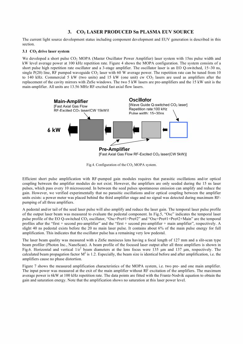
We developed a short pulse CO2 MOPA (Master Oscillator Power Amplifier) laser system with 15ns pulse width and kW level average power at 100 kHz repetition rate. Figure 4 shows the MOPA configuration. The system consists of a short pulse high repetition rate oscillator and a 3-stage amplifier. The oscillator laser is an EO Q-switched, 15~30 ns, single P(20) line, RF pumped waveguide CO2 laser with 60 W average power. The repetition rate can be tuned from 10 to 140 kHz. Commercial 5 kW (two units) and 15 kW (one unit) cw CO2 lasers are used as amplifiers after the replacement of the cavity mirrors with ZnSe windows. The two 5 kW lasers are pre-amplifiers and the 15 kW unit is the main-amplifier. All units are 13.56 MHz RF-excited fast axial flow lasers.
Fig.4. Configuration of the CO2 MOPA system.
Efficient short pulse amplification with RF-pumped gain modules requires that parasitic oscillations and/or optical coupling between the amplifier modules do not exist. However, the amplifiers are only seeded during the 15 ns laser pulses, which pass every 10 microsecond. In between the seed pulses spontaneous emission can amplify and reduce the gain. However, we verified experimentally that no parasitic oscillations and/or optical coupling between the amplifier units exists: a power meter was placed behind the third amplifier stage and no signal was detected during maximum RF-pumping of all three amplifiers.
A pedestal and/or tail of the seed laser pulse will also amplify and reduce the laser gain. The temporal laser pulse profile of the output laser beam was measured to evaluate the pedestal component. In Fig.5, “Osc” indicates the temporal laser pulse profile of the EO Q-switched CO2 oscillator, “Osc+Pre#1+Pre#2” and “Osc+Pre#1+Pre#2+Main” are the temporal profiles after the “first + second pre-amplifier” and the “first + second pre-amplifier + main amplifier”, respectively. A slight 40 ns pedestal exists before the 20 ns main laser pulse. It contains about 6% of the main pulse energy for full amplification. This indicates that the oscillator pulse has a remaining very low pedestal.
The laser beam quality was measured with a ZnSe meniscus lens having a focal length of 127 mm and a slit-scan type beam profiler (Photon Inc., NanoScan). A beam profile of the focused laser output after all three amplifiers is shown in Fig.6. Horizontal and vertical 1/e2 beam diameters at the lens focus were 135 µm and 137 µm, respectively. The calculated beam propagation factor M2 is 1.2. Especially, the beam size is identical before and after amplification, i.e. the amplifiers cause no phase distortion.
Figure 7 shows the measured amplification characteristics of the MOPA system, i.e. two pre- and one main amplifier. The input power was measured at the exit of the main amplifier without RF excitation of the amplifiers. The maximum average power is 6kW at 100 kHz repetition rate. The data points are fitted with the Frantz-Nodvik equation to obtain the gain and saturation energy. Note that the amplification shows no saturation at this laser power level.
Main-Amplifier [Fast Axial Gas Flow RF-Excited CO2 laser(CW 15kW)]
Pre-Amplifier [Fast Axial Gas Flow RF-Excited CO2 laser(CW 5kW)]
Oscillator [Wave Guide Q-switched CO2 laser] Repetition rate:100 kHz Pulse width: 15~30ns
6 kW

Fig. 5. Temporal laser pulse profile. Fig. 6. Focusability of the CO2 laser beam.
0
1000
2000
3000
4000
5000
6000
7000
0 10 20 30 40
Input Power [W]
Am
plif
ied
Ou
tpu
t P
ow
er
[W]
Fig. 7. Amplification characteristics of the CO2 MOPA system.
3.2 Sn droplet target supply
We develop the Sn droplet supply system based on our Xe droplet supply system7. The liquid Sn is ejected through a nozzle into the vacuum chamber. The harmonic oscillation of a piezoelectric transducer (PZT) induces a Rayleigh instability11 that causes the liquid jet to break up into uniform droplets.
Figure 8 shows a generated Sn droplet chain inside the vacuum chamber. The droplets are generated with a diameter of about 130 µm and a speed of about 17 m/s. Currently, a high speed of 70-m/s Sn droplet supply system is developed for irradiation with the high power CO2 MOPA system.
0
0.2
0.4
0.6
0.8
1
1.2
-150 -100 -50 0 50 100 150
Position (um)
Norm
aliz
ed inte
nsity
!"#$%"&'()
*+#'$,()
0
0.2
0.4
0.6
0.8
1
1.2
0 50 100 150 200
Time [ns]
Norm
aliz
ed Inte
nssity [arb
.Units]
OscOsc+Pre#1+Pre#2(920W)Osc+Pre#1+Pre#2+Main(2.6kW)
FWHM:20ns

0
0.002
0.004
0.006
0.008
0.01
0 15 30 45 60 75 90
angle [deg]
de
po
sitio
n r
ate
[n
m/m
J p
ls]
0T
1T
Fig. 8. Sn droplet chain with a diameter of 130 µm, speed of 17 m/s.
3.3 Magnetic field mitigation
The fast ions from a laser produced plasma are controlled by a magnetic field5,6. Figure 9 shows the Faraday cup signal from Nd:YAG laser generated Sn plate target plasma with and without a magnetic field. The Faraday cup signal decreased below the detection limit (about 3 orders) by applying a magnetic field of 1T. The QCM signal, on the other hand, did not change applying a magnetic field between 0T and 1T as shown in Fig. 10. Hence, the ions only weakly influence the deposition. From the experimental results it is estimated that the ion effect on deposition is below 1%. In case of a Nd:YAG drive laser and a Sn target, debris mitigation is therefore much more important than ion mitigation. For the CO2 laser, however, the observed sputtering rate is higher than the deposition rate. Since the generated ion number is approximately equal to the amount of debris, (the observed erosion rate is close to zero) it can be concluded that the amount of debris is 1% or less as compared with the Nd:YAG laser.
Fig. 9. Faraday cup signal with and without a magnetic field. Fig. 10. Sn deposition rate with and without a magnetic field.
3.4 EUV generation
A preliminary experiment without any system optimization was done with the high power CO2 MOPA laser and a solid Sn target. The laser output power was 5 kW at a repetition rate of 100 kHz and a rotating Sn disk target was used. The
-0.1
0
0.1
0.2
0.3
0.4
0.5
0.6
0 5 10 15 20 25 30
time [us]
Ion s
ignal [V
]
0T
1T

laser incidence angle to the Sn disk normal was 45 degree. The generated EUV in-band energy was measured with a Flying circus 2 energy meter placed at an angle of 15 degree to the target normal. Figure 11 shows the EUV energy of the plasma source into 2πsr and 2% bandwidth. The average EUV output power at the primary is 110W, i.e. the average conversion efficiency of 2.2% was obtained.
0
0.2
0.4
0.6
0.8
1
1.2
1.4
1.6
0 100 200 300 400 500 600 700 800
Number of pulses
EU
V e
nerg
y [
mJ]
Fig. 11. EUV pulse energy at primary source.
Table 2 lists the IF EUV power as a function of laser power and CE. The assumed EUV transfer efficiency from the primary source to the intermediate focus is 28% for the upper column and 36% for the lower column. An in-band EUV power of 40W is generated with the current laser power of 5 kW at a CE of about 2.2% with 36% transfer efficiency. The required 100 W will be generated from a 7.5 kW CO2 laser at a CE of 4%. The full CO2 MOPA system for a 100-W EUV source will have a compact design due to the proper choice of modern laser technology.
Table 2. Estimated EUV power at the intermediate focus.

4. SUMMARY We develop a LPP source for high volume manufacturing EUV lithography that is based on a high power CO2 MOPA system and a tin droplet target. A maximum conversion efficiency of 4.5% was measured for a CO2 laser driven Sn plasma having a narrow spectrum at 13.5nm. Debris Mitigation for a CO2 laser produced Sn plasma system is very promising, since only low Sn deposition on samples has been observed. A laser output power of 6 kW was achieved with a single beam having very good beam quality. The laser power will increase with the correct choice of laser technology. The average EUV output power at the primary is 110W equivalent to 40 W at the intermediate focus. We conclude that the CO2 laser driven Sn light source is the most promising candidate for HVM EUVL due to its scalability, high efficiency and long collector mirror lifetime.
ACKNOWLEDGEMENTS This work was supported by the New Energy and Industrial Technology Development Organization (NEDO), Japan.
REFERENCES
1. Rob Hartman, Closing address presentation at 2006 International EUVL Symposium, October 2006, Barcelona, Spain.
2. K. Nicklaus, M. Hoefer, H. D. Hoffmann, J. Luttmann, R. Wester, R. Poprawe, “MOPA with kW average power and multi MW peak power: experimental results, theoretical modeling and scaling limits” Proc. SPIE, 6100, 314-324 (2006).
3. K. Nishihara, A. Sasaki, A. Sunahara, and T. Nishikawa, EUV Sources for Lithography, Chap. 11, ed. V. Bakshi, SPIE, Bellingham, 2005.
4. H. Tanaka, A. Matsumoto, K. Akinaga, A. Takahashi, and T. Okada, “Comparative study on emission characteristics of extreme ultraviolet radiation from CO2 and Nd:YAG laser-produced tin plasmas” Appl. Phys. Lett. 87, 041503 (2005)
5. H. Komori, Y. Imai, G. Soumagne, T. Abe, T. Suganuma, and A. Endo, “Magnetic field ion mitigation for EUV light sources,” Proc. SPIE 5751, 859 (2005)
6. Akira Endo, Hideo Hoshino, Tatsuya Ariga, Taisuke Miura, Yoshifumi Ueno, Masaki Nakano, Hiroshi Komori, Georg Soumagne, Hakaru Mizoguchi, Akira Sumitani, Koichi Toyoda, "Development Status of HVM Laser Produced Plasma EUV Light Source", Proc. Int. Sematech EUVL Symposium, Barcelona (2006).
7. H. Mizoguchi, A. Endo, T. Ariga, T. Miura, H. Hoshino, Y. Ueno, M. Nakano, H. Komori, A. Sumitani, T. Abe, T. Suganuma, G. Soumagne, H. Someya, Y. Takabayashi, K. Toyoda, ” Development of CO2 laser produced Xe plasma EUV light source for microlithography,” Proc. SPIE, 6151, 61510S (2006).
8. B. E. Jurczyk, E. V. Lopez, J. Neumann and D. N. Ruzic, “Illinois Debris-mitigation EUV Applications Laboratory (IDEAL)” Proc. SPIE, 5374, 695-701, (2004)
9. R. J. Anderson, D. A. Buchenauer, L. Klebanoff, O. R. Wood II and N. V. Edwards, “The erosion of materials exposed to a laser-pulsed plasma (LPP) extreme ultraviolet (EUV) illumination source”, Proc. SPIE, 5374, 710-719, (2004)
10. T. Ariga, H. Hoshino, T. Miura, A. Endo, “High-average-power CO2 laser MOPA system for Sn target LPP EUV light source,” Proc. SPIE, 6454, 645403 (2007).
11. Lord Rayleigh, F.R.S “On the instability of jets” Proc. London mth Soc. 10(4)4-13 (1878)