klein heidelberg – the world's first operational bistatic radar system
TRANSCRIPT

1
____________________________________________________
Klein Heidelberg – a WW2 bistatic radar system that
was decades ahead of its time1
Hugh Griffiths and Nicholas Willis*
____________________________________________________
ABSTRACT
We present a description and analysis of the German WW2 bistatic radar system Klein
Heidelberg. A brief account is given of the nature of the electronic war between the Allied
bomber aircraft and the German air defence system, to show the context in which the Klein
Heidelberg system evolved. This is followed by a description of the development of Klein
Heidelberg, a technical description, and an assessment of its performance. Next, a discussion
of its operational significance, of what happened after WW2, and finally some conclusions and
some lessons learned that may be relevant to the development of present-day bistatic radar
systems. In particular, we show that its performance was impressive, yielding detection ranges
of Allied bombers in excess of 300 km, but that it became operational too late to make any
significant difference to the course of WW2.
1. CONTEXT
The term bistatic refers to a radar in which the transmitter and receiver are in separate locations
(Figure 1). In practice this means that they are separated by a considerable distance, usually
understood to be of the order of the target range, so as to distinguish it from smaller separations
designed only for receiver isolation from the transmit signal, and this gives bistatic radars some
different and distinct properties compared to conventional monostatic radars [2, 3]. Bistatic
radar is presently a subject of significant interest and research in many countries worldwide,
which is reflected in the large volume of publications in academic journals and at conferences.
The purpose of this piece is to present and analyse information on a German WW2 bistatic
1 This is a substantially-expanded version of a paper published in IEEE Transactions on Aerospace and Electronic
Systems [1]. It places greater emphasis on the historical background, and includes information that could not be
included in that paper for reasons of space. In addition, online publication of this version should allow wider access,
and should allow easy correction and updating as and when new information is brought to our attention – as we hope
very much that it will. But if reference is made to this work, please cite the published reference [1].
* Hugh Griffiths holds the THALES/Royal Academy of Engineering Chair of RF Sensors at University College
London. Nick Willis is retired (sort of). Email addresses: [email protected], [email protected]

2
radar system called Klein Heidelberg (hereafter denoted KH) which was used to enhance
German air defences by exploiting transmissions from the British Chain Home (CH) radar
transmitter, as shown in Figure 1. Whilst some scattered information about this system has
been known for many years, recently-discovered material has greatly increased our knowledge
about KH and its performance, and the relevance to present-day systems means that this
discussion may be timely.
This account begins with a review of the properties of bistatic radar, to explain the present
interest and to set the context for what follows. Next we give a short summary of German WW2
air defence radar and electronic warfare. This is followed by an updated account of the
development of KH, a technical description, and an assessment of its performance. We then
discuss its operational significance during WW2, what happened after WW2, and finally we
present some conclusions and lessons learned, particularly with respect to present-day bistatic
radar systems.
Figure 1. Bistatic radar. Many of the properties are a function of the bistatic triangle formed by the transmitter, target and receiver.
Properties of bistatic radar
The transmitter and receiver of a bistatic radar are purposely separated in order to achieve a
technical, operational or cost benefit when compared to other sensors, including monostatic
radars.
An example of the technical benefit is to improve target location accuracy by (a) using a
multistatic configuration consisting of multiple transmitters and/or receivers, again separated by
considerable distances, such that the geometric dilution of precision (GDOP) is improved, or (b)
3
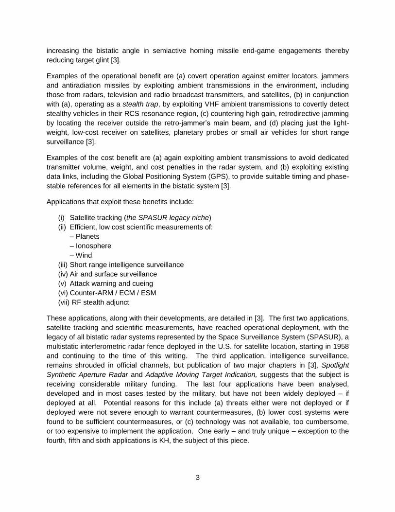
increasing the bistatic angle in semiactive homing missile end-game engagements thereby
reducing target glint [3].
Examples of the operational benefit are (a) covert operation against emitter locators, jammers
and antiradiation missiles by exploiting ambient transmissions in the environment, including
those from radars, television and radio broadcast transmitters, and satellites, (b) in conjunction
with (a), operating as a stealth trap, by exploiting VHF ambient transmissions to covertly detect
stealthy vehicles in their RCS resonance region, (c) countering high gain, retrodirective jamming
by locating the receiver outside the retro-jammer‟s main beam, and (d) placing just the light-
weight, low-cost receiver on satellites, planetary probes or small air vehicles for short range
surveillance [3].
Examples of the cost benefit are (a) again exploiting ambient transmissions to avoid dedicated
transmitter volume, weight, and cost penalties in the radar system, and (b) exploiting existing
data links, including the Global Positioning System (GPS), to provide suitable timing and phase-
stable references for all elements in the bistatic system [3].
Applications that exploit these benefits include:
(i) Satellite tracking (the SPASUR legacy niche)
(ii) Efficient, low cost scientific measurements of:
– Planets
– Ionosphere
– Wind
(iii) Short range intelligence surveillance
(iv) Air and surface surveillance
(v) Attack warning and cueing
(vi) Counter-ARM / ECM / ESM
(vii) RF stealth adjunct
These applications, along with their developments, are detailed in [3]. The first two applications,
satellite tracking and scientific measurements, have reached operational deployment, with the
legacy of all bistatic radar systems represented by the Space Surveillance System (SPASUR), a
multistatic interferometric radar fence deployed in the U.S. for satellite location, starting in 1958
and continuing to the time of this writing. The third application, intelligence surveillance,
remains shrouded in official channels, but publication of two major chapters in [3], Spotlight
Synthetic Aperture Radar and Adaptive Moving Target Indication, suggests that the subject is
receiving considerable military funding. The last four applications have been analysed,
developed and in most cases tested by the military, but have not been widely deployed – if
deployed at all. Potential reasons for this include (a) threats either were not deployed or if
deployed were not severe enough to warrant countermeasures, (b) lower cost systems were
found to be sufficient countermeasures, or (c) technology was not available, too cumbersome,
or too expensive to implement the application. One early – and truly unique – exception to the
fourth, fifth and sixth applications is KH, the subject of this piece.

4
Bistatic radar actually has a long and fascinating history. Some of the first radar experiments
were bistatic, using forward scatter „fences‟ to detect aircraft [2, 3]. Since then, interest has
varied cyclically, with resurgences having a period of 15-20 years over the past seventy years,
putting us into a third cycle. And there is now good reason to believe that the technology is
available to economically implement the applications listed above – given the operational
requirements to do so.
KH was the first hitchhiker. A hitchhiker is a bistatic receiver operating with the transmitter of a
separate and usually independent monostatic radar. The monostatic radar can be friendly or
hostile, and in the case of KH was hostile. The hitchhiker can be considered for all but the first
of the seven applications. The term „hitchhiker‟ was coined in the U.S. in the 1970s and, sadly,
with scant knowledge of past bistatic radar developments, including Klein Heidelberg. However,
it is now generally understood and accepted in most radar communities.
Klein Heidelberg or Klein Heidelberg–Parasit, to give it its full name, was developed by the
Germans in WW2 for long-range air surveillance in the presence of ECM and ESM (applications
iv and vi), as an adjunct to their Kammhuber Line. Six KH receivers were deployed along the
Dutch, Belgian and French side of the English Channel and North Sea, all of which hitchhiked
off the British Chain Home (CH) transmitters. Its principal benefit was covert and thus un-
jammed operation in response to Allied jamming and chaff deployed against the VHF/UHF
monostatic radars in the Kammhuber Line. Emitter locators were countered as well.
Furthermore, this type of hostile hitchhiking discouraged deploying conventional ECM against
KH since it would also degrade the performance of CH.
Until recently, little was known about KH‟s characteristics and antenna configuration, the
number deployed and its effectiveness in aiding German surveillance of allied bombing raids
from England. However, some more recently-discovered documents [4, 5, 6] have provided
substantially more information. This paper summarizes the new information and assesses the
rationale for developing KH and its resulting effectiveness.
So why be concerned with such an ancient and obscure military artefact? To quote George
Santayana, „Those who cannot learn from history are doomed to repeat it‟. Thus, such historical
studies may allow us to understand how the originators of particular ideas were inspired and
how their sparks of genius were generated. Many modern ideas that we suppose to be original
were actually first conceived many years ago. Equally, it may be that ideas from the past, which
did not succeed because the necessary technology was not available, may now be more
promising – as with the case of bistatic radars.
2. HISTORICAL PERSPECTIVE OF GERMAN AIR DEFENCE RADAR AND ELECTRONIC
WARFARE
To understand the origins of KH it is necessary to understand something of the cat-and-mouse
game of countermeasures and counter-countermeasures used by both sides in the battle
5
between Allied bombers and German air defence in WW2. These were essentially the origins of
Electronic Warfare [7, 8].
German WW2 air defence radars
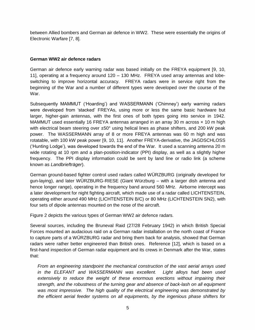
German air defence early warning radar was based initially on the FREYA equipment [9, 10,
11], operating at a frequency around 120 – 130 MHz. FREYA used array antennas and lobe-
switching to improve horizontal accuracy. FREYA radars were in service right from the
beginning of the War and a number of different types were developed over the course of the
War.
Subsequently MAMMUT („Hoarding‟) and WASSERMANN („Chimney‟) early warning radars
were developed from „stacked‟ FREYAs, using more or less the same basic hardware but
larger, higher-gain antennas, with the first ones of both types going into service in 1942.
MAMMUT used essentially 16 FREYA antennas arranged in an array 30 m across × 10 m high
with electrical beam steering over ±50° using helical lines as phase shifters, and 200 kW peak
power. The WASSERMANN array of 8 or more FREYA antennas was 60 m high and was
rotatable, with 100 kW peak power [9, 10, 11]. Another FREYA-derivative, the JAGDSCHLOSS
(„Hunting Lodge‟), was developed towards the end of the War. It used a scanning antenna 20 m
wide rotating at 10 rpm and a plan-position-indicator (PPI) display, as well as a slightly higher
frequency. The PPI display information could be sent by land line or radio link (a scheme
known as Landbriefträger).
German ground-based fighter control used radars called WÜRZBURG (originally developed for
gun-laying), and later WÜRZBURG-RIESE (Giant Würzburg – with a larger dish antenna and
hence longer range), operating in the frequency band around 560 MHz. Airborne intercept was
a later development for night fighting aircraft, which made use of a radar called LICHTENSTEIN,
operating either around 490 MHz (LICHTENSTEIN B/C) or 80 MHz (LICHTENSTEIN SN2), with
four sets of dipole antennas mounted on the nose of the aircraft.
Figure 2 depicts the various types of German WW2 air defence radars.
Several sources, including the Bruneval Raid (27/28 February 1942) in which British Special
Forces mounted an audacious raid on a German radar installation on the north coast of France
to capture parts of a WÜRZBURG radar and bring them back for analysis, showed that German
radars were rather better engineered than British ones. Reference [12], which is based on a
first-hand inspection of German radar equipment and its crews in Denmark after the War, states
that:
From an engineering standpoint the mechanical construction of the vast aerial arrays used
in the ELEFANT and WASSERMANN was excellent. Light alloys had been used
extensively to reduce the weight of these enormous erections without impairing their
strength, and the robustness of the turning gear and absence of back-lash on all equipment
was most impressive. The high quality of the electrical engineering was demonstrated by
the efficient aerial feeder systems on all equipments, by the ingenious phase shifters for
6
electrical beam swinging on the WASSERMANN and MAMMUT and by the facilities for
rapid change of frequency without appreciable loss of sensitivity on the WASSERMANN M2.
Figure 2. German WW2 air defence radars (Svejgaard [55]).
7
Their radar operators, though, were not so well trained, and the comfort of the operators does
not seem to have been a high priority. R.V. Jones [7] describes that the radar operator captured
in the Bruneval Raid, although very co-operative under interrogation, was of low technical
competence and in fact up to that point in the War had spent more time in jail that out of it.
When, after the War, in a conversation with General Martini (Head of German Signals and
Radar) Jones had commented on this, Martini responded that his demands for staff were
treated with low priority and that he had to make do with personnel regarded as unsuitable for
other roles. Furthermore, the Germans were unable to draw on the skills and experience of
amateur radio operators, since this had been banned by Hitler before the War. Another source
[13] states that that the operators of the FREYA-LZ radar had to enter the cabin in a particular
order, since once inside there was no room for one operator to pass another. Emphatic
confirmation of all of this is provided in the report on Exercise POST MORTEM [12], discussed
later in this section, which reports that:
In designing the radar control cabins little attention had been paid to the comfort of the
operating crews. The ventilation, lighting and seating on many of the equipments could
hardly have been worse. The operators, working under these unsavoury conditions,
compared unfavourably in their standards of intelligence, training, operating discipline and
initiative with British crews.
As well as FREYA, MAMMUT, WASSERMANN and JAGDSCHLOSS a large HF radar called
ELEFANT was installed in the Netherlands, and subsequently a version called SEE-ELEFANT
on the island of Rømø off the west coast of Denmark [14, 15, 16]. They have been confused
with KH, in part due to physical similarities in the receiving antenna. However they were
separate developments. The ELEFANTs are described in more detail in Appendix A.
German WW2 air defence system
The German air defence system consisted of a network of radar stations, each known as a
Stellung (site) and denoted by the codename of an animal, bird, fish or flower, with the initial
letter corresponding to that of a nearby town or village. These were designated as first-order,
second-order, or third-order sites. The third-order Stellungen reported information using coded
radio transmissions to first-order Stellungen; the second-order Stellungen formed an air picture
and transmitted that to first-order Stellungen. The first-order Stellungen combined their own
information with that from the second- and third-order Stellungen, filtered out friendly aircraft
detections, and transmitted the information on to a Himmelbett Operations Room. Here the
overall picture was assembled, and the information passed back to the first-, second- and third-
order Stellungen. The radar information was supplemented by visual observers and reports
from radio interception stations. The whole was organised in a layered scheme of zones called
the Kammhuber Line2. Figure 3 shows the locations of Stellungen in north-west Europe.
Later on the German night-fighters adopted Wilde Sau (Wild Boar) tactics, in which fighters
operated individually, relying solely on data from the LICHTENSTEIN radar coupled with the
2 This configuration was so effective it was copied by some Allied countries after WW2.

8
pilot‟s initiative and judgement, in contrast to the Zahme Sau (Tame Boar) tactics where fighters
were guided by ground control to specific bomber targets.
British and German countermeasures and counter-countermeasures
As soon as British scientists learned about the German air defence system, principally from
decoded communications intercepts and from interception of the radar signals themselves, they
set about devising jamming and deception techniques. The story is splendidly and
authoritatively told in R.V. Jones‟s book Most Secret War [7]. One of the first jammers was
MANDREL, a low-power (~2W) noise barrage jammer employed against FREYA and its
derivatives, introduced early in December 1942, and carried either by Stirling bombers of 199
Squadron (self-screening) or by Defiant aircraft of 515 Squadron (stand-off). When MANDREL
was introduced, Bomber Command losses (expressed in losses per 3,000 sorties) fell
significantly (Figure 4) [11, 17]. This plot also shows the dates of introduction of some of the
other countermeasures, and shows that in general, each countermeasure had an immediate
effect which lasted for a few weeks until the Germans developed an appropriate counter-
countermeasure or tactic.
Figure 3. Map of Luftwaffe radar sites (Stellungen) in north-west Europe (Svejgaard [54]).
In response the Germans widened the band over which FREYA could operate, first to 120 – 140
MHz then to 120 – 160 MHz, and ultimately even wider. Thus the frequency coverage of
MANDREL had to be increased accordingly. Also, automatic on-off switching of MANDREL was

9
incorporated to attempt to prevent the enemy from homing on the jammer signal. MANDREL
SCREEN [12, 17] was a more sophisticated implementation of MANDREL, introduced in June
1944 (171 and 199 Squadrons), with pairs of jamming aircraft working together to give full
coverage of the band which by then had widened considerably. MANDREL was only one of a
range of countermeasures; others included JOSTLE (high power jamming of communications),
AIRBORNE CIGAR (spot frequency jamming of VHF communications), PIPERACK (jamming of
AI radar) and CARPET (jamming of WÜRZBURG) [12].
German scientists developed their own countermeasures and counter-countermeasures, many
of which were ingenious and sophisticated, including intercept receivers for the H2S radar
transmissions of the British bomber aircraft, devices to trigger the Identification Friend or Foe
(IFF) of the bomber aircraft to give away their position (FREYA-FLAMME), as well as devices to
distinguish aircraft from chaff on the basis of Doppler (WURZLAUS, FREYA-LAUS,
WASSERFLOH) and on the basis of the modulation of echoes by aircraft propellors
(NÜRNBERG) [18].
Figure 4. Plot of RAF Bomber Command losses in WW2 (from [17]; also reproduced in [11]). The horizontal axis is scaled per 3,000 sorties. Also shown are the dates of introduction of
various Allied countermeasures. The losses shows a sharp drop around June 1944, after which the Germans lost the use of their radar stations in France and Belgium as they were recaptured by the advancing Allied forces. Also shown (red arrows) are the dates by which the first KH was
operational (December 1943) and by which three KHs were operational (summer 1944).

10
Both sides, independently, had developed chaff as a means of generating a large false target
from scattered strips of aluminium foil of length corresponding to half the wavelength of the
victim radar [19]. In the UK much of this work had been done by Joan Curran, who was the only
female scientist at TRE, and a rather remarkable woman3. The scheme was given the
codename WINDOW by A.P. Rowe, the Superintendent of TRE, as a randomly-chosen name
that bore no relation to its true meaning. However, it had been realised that as soon as Window
was deployed, the Germans would find the aluminium strips, immediately understand the
principles and likely use it against Allied radars – which at the time had no counter-
countermeasures against chaff. Churchill therefore did not allow the use of Window until the
bombing raids on Hamburg, 23-27 July 1943 (Operation GOMORRAH). But in fact German
scientists had already discovered the same principle in early 1940 (known as DÜPPEL4), and
kept it highly secret on the orders of Goering, for exactly the same reasons. There is also
evidence that it had also been discovered by Japanese scientists (it was known as giman-shi –
literally „deceiving paper‟) and used in May 1943 to jam American SCR-268 radars during a raid
on Guadalcanal [10].
Exercise Post Mortem
POST MORTEM [11, 12] was an exercise carried out by the Royal Air Force in June and July
1945 immediately after the end of WW2 in Europe (8 May 1945), against the German air
defence system in Denmark and Schleswig-Holstein, which had been captured largely intact.
Its purpose was to evaluate the effectiveness of different types and combinations of
countermeasures. The radars, signals interception (Y-Dienst), observer corps, and the
operations rooms, were manned by their German crews, who were surprisingly cooperative and
seemed eager to demonstrate the efficiency of their system – particularly the more senior
personnel [12] – although Brown [11] records that the Blitzmädel plotters (equivalent to WAAFs)
in the operations room at Grove were not so cooperative because one of their number had been
assaulted (or at least, propositioned) by a British soldier who was present in the operations
room.
A total of fourteen exercises were planned, of which 11 were flown, with three cancelled due to
bad weather, and the first used no countermeasures as a reference against which to compare
the others. The raids were substantial, with seven of them involving more than 200 heavy
bombers, and were carried out in daylight.
The exercise would have provided a unique opportunity to observe at first hand the German
radars being operated by their crews and to assess the performance of the radars and the air
defence system as a whole. It also showed that the effectiveness of MANDREL, and of Radio
Countermeasures (RCM) in general, were by no means total.
3 She had studied at Cambridge University in the days before degrees were awarded there to female students (which
would not be till 1948), and she had rowed in the first Women‟s Boat Race in 1935. 4 Düppel was the name of the location, near Berlin, of the Telefunken laboratories [24]. It is a coincidence that it
sounds rather like the English word „dipole‟.
11
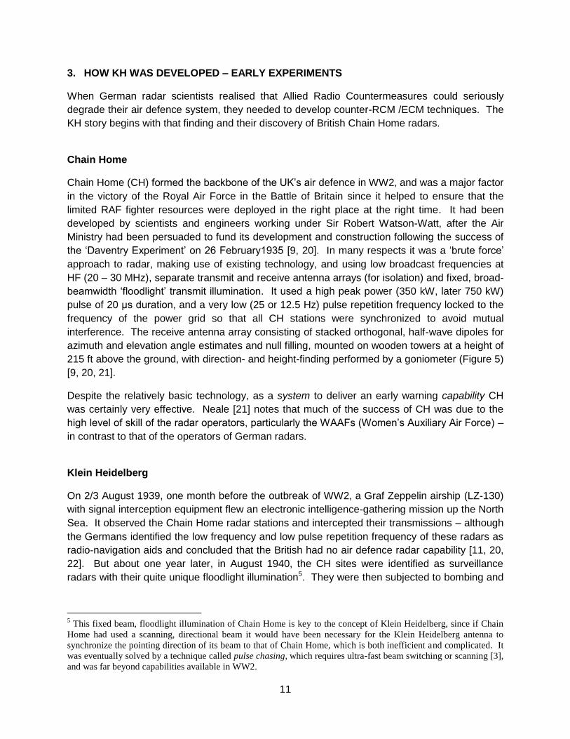
3. HOW KH WAS DEVELOPED – EARLY EXPERIMENTS
When German radar scientists realised that Allied Radio Countermeasures could seriously
degrade their air defence system, they needed to develop counter-RCM /ECM techniques. The
KH story begins with that finding and their discovery of British Chain Home radars.
Chain Home
Chain Home (CH) formed the backbone of the UK‟s air defence in WW2, and was a major factor
in the victory of the Royal Air Force in the Battle of Britain since it helped to ensure that the
limited RAF fighter resources were deployed in the right place at the right time. It had been
developed by scientists and engineers working under Sir Robert Watson-Watt, after the Air
Ministry had been persuaded to fund its development and construction following the success of
the „Daventry Experiment‟ on 26 February1935 [9, 20]. In many respects it was a „brute force‟
approach to radar, making use of existing technology, and using low broadcast frequencies at
HF (20 – 30 MHz), separate transmit and receive antenna arrays (for isolation) and fixed, broad-
beamwidth „floodlight‟ transmit illumination. It used a high peak power (350 kW, later 750 kW)
pulse of 20 μs duration, and a very low (25 or 12.5 Hz) pulse repetition frequency locked to the
frequency of the power grid so that all CH stations were synchronized to avoid mutual
interference. The receive antenna array consisting of stacked orthogonal, half-wave dipoles for
azimuth and elevation angle estimates and null filling, mounted on wooden towers at a height of
215 ft above the ground, with direction- and height-finding performed by a goniometer (Figure 5)
[9, 20, 21].
Despite the relatively basic technology, as a system to deliver an early warning capability CH
was certainly very effective. Neale [21] notes that much of the success of CH was due to the
high level of skill of the radar operators, particularly the WAAFs (Women‟s Auxiliary Air Force) –
in contrast to that of the operators of German radars.
Klein Heidelberg
On 2/3 August 1939, one month before the outbreak of WW2, a Graf Zeppelin airship (LZ-130)
with signal interception equipment flew an electronic intelligence-gathering mission up the North
Sea. It observed the Chain Home radar stations and intercepted their transmissions – although
the Germans identified the low frequency and low pulse repetition frequency of these radars as
radio-navigation aids and concluded that the British had no air defence radar capability [11, 20,
22]. But about one year later, in August 1940, the CH sites were identified as surveillance
radars with their quite unique floodlight illumination5. They were then subjected to bombing and
5 This fixed beam, floodlight illumination of Chain Home is key to the concept of Klein Heidelberg, since if Chain
Home had used a scanning, directional beam it would have been necessary for the Klein Heidelberg antenna to
synchronize the pointing direction of its beam to that of Chain Home, which is both inefficient and complicated. It
was eventually solved by a technique called pulse chasing, which requires ultra-fast beam switching or scanning [3],
and was far beyond capabilities available in WW2.

12
jamming, though this only lasted for a few months and was largely ineffective [20, 22]. This one
year delay turns out to be a critical factor in assessing the utility of KH in the Kammhuber Line.
Figure 5. CHAIN HOME (Neale [21]; the photograph is of the CH at Poling in Sussex [23]).

13
These observations, coupled later with the realisation of the need to devise an early warning
radar that did not suffer from the various Allied countermeasures, led Dipl.-Ing Wächter of the
Telefunken company to conclude that it ought to be possible to build a completely passive radar
receiver that used the British Chain Home signals as its illuminating source. Because such a
receiver radiated no signal it would be undetectable by British intercept receivers, and thus be
far less susceptible to jamming or to chaff. Further, even when discovered, the use of jamming
or chaff would have upset the operation of the Chain Home system itself. Figure 6, adapted
from Hoffmann‟s book which was published in 1965 [24], shows the basic principle.
Some information on Wächter‟s background and on the initial experiments is provided by
Trenkle [25]. Apart from this and British intelligence reports, which were highly classified till
their release after a period of 30 years, there is little published information on Klein Heidelberg.
Figure 6. Diagram of the principle of Klein Heidelberg showing a KH receiver at Oostvoorne using a transmission from a CH radar at Dover. A measurement of the bistatic range RT + RR
defines an ellipse on which the target lies (adapted from Hoffmann [24]).
Trenkle provides the following historical perspective. The basic scheme was developed by
Telefunken in 1942 in co-operation with the Central Research Establishment of the RPZ6. A
number of research models were tried, for example near Cherbourg in 1942/43. Reference [6]
describes some preliminary trials at the jammer station NACHTFALTER („Moth‟) on Mont
Couple between Calais and Boulogne7. The trials station had a primitive D/F (Direction Finding)
6 Reichspostzentralamt (German Post Office).
7 Bauer notes that this site also housed the main jamming equipment used against British radars during the decisive
Channel Dash of 12 February 1942 (Operation CERBERUS) in which the German battlecruisers Scharnhorst,
Gneisenau and the heavy cruiser Prinz Eugen escaped from the French port of Brest through the English Channel to
their home base in Germany.

14
array using just two dipoles, but a larger antenna (with higher gain and higher directivity) was
then developed for the full system.
Figure 6 and the brief paragraphs by Hoffmann [24], Trenkle [25] and Price [8] represent the
available information about KH up to 1980. Furthermore, a detailed and comprehensive 1978
description of the German night fighter force in WW2 [18] makes no mention of KH. So up to
this time it had generated virtually no interest in the air defence community, and only passing
interest in the (more limited) bistatic radar community.
The state of KH information significantly expanded starting in the mid 1990s and continuing into
the 21st Century. Specifically, Goebel [10], Brown [11], Svejgaard [26], and a number of WW2
British intelligence reports, most notably the reports in late 1944 of the interrogation of two
German KH operators [4, 5], shed new light on KH equipment, operation, performance and
deployment, including photographs and drawings. We now know that six KH sites were
deployed along the coast of France, Belgium and The Netherlands, and that their detection
range could exceed 300 km, sometimes 400 km. The following paragraphs summarize this new
information.
Figure 7. Map showing the locations of the six Klein Heidelberg Stellungen (Svejgaard [26]).

15
Figure 8. The Klein Heidelberg at TAUSENDFÜSSLER (Cherbourg). In this installation the Wassermann-S antenna was retained on the rear side of the KH array. In both pictures, but particularly the lower one, substantial damage is evident to the antenna, the tower and the
bunker (Conseil Régional de Basse-Normandie / US National Archives).

16
Figure 9. The second Klein Heidelberg, at BIBER (Oostvoorne). In this installation the Wassermann-S antenna is absent. The lower picture shows an expanded view in which the
dipole elements and the wire mesh reflector are visible (© Jeroen Rijpsma).

17
The first Klein Heidelberg system was established at Boulogne (Stellung BULLDOGGE) by a
detachment of the Luftwaffe Air Signals Experimental Regiment and was operational towards
the end of 1943. With this system, Allied aircraft could be detected when still over England, and
could be followed all the way to Germany [6]. As a result a second system was then
established at Oostvoorne in the Netherlands (BIBER), becoming operational in Spring of 1944,
and then subsequently four more at Vaudricourt (SKORPION), Oostende in Belgium
(BREMSE), Cap d‟Antifer (AUERHAHN) and Cherbourg (TAUSENDFÜSSLER). Figure 7
shows the locations of these Stellungen. In each case the antenna was mounted on the tower
of a WASSERMANN-S radar (Figure 8), and made use of the L480 bunker of the
WASSERMANN, though in at least two cases (BIBER and SKORPION) the WASSERMANN
antenna was absent (Figure 9). Figure 10 shows a plan view of the L480 bunker, in this case
from Stellung BIBER [27].
Figure 11 shows an aerial photograph (exact date unknown) of the area around the first KH, at
Boulogne. The feature at the right-hand corner of the picture is the Colonne de la Grande
Armée: a monument to Napoleon which might be considered to be a counterpart to Nelson‟s
Column in Trafalgar Square in the centre of London. Figure 12 shows a sketch of the location
of the KH antenna with respect to the monument, and it can be seen that in Figure 11 there is a
conspicuous, slender shadow at this location. However, the shadow seems too thin to be that
of the WASSERMANN or KH antenna, so is perhaps most likely to be the shadow of the
WASSERMANN-S tower without any antennas. Figure 13 shows an aerial photograph of the
L480 bunker of the TAUSENDFÜSSLER (Cherbourg) KH.
Figure 10. Plan of the L480 bunker type that housed the Klein Heidelberg radar (this example is from Stellung BIBER). The antenna was located over the cross on the left-hand side (from
Radarstellung BIBER: Kustverdediging op Voorne 1940 – 1945, Jeroen Rijpsma and Klaas van Brakel, 2005).

18
Figure 11. Wartime aerial reconnaissance photograph of the area around the BULLDOGGE (Boulogne) KH. The Napoleon Monument is clearly visible to the right of the picture, and a shadow just to the south-west of that which is probably the Wassermann-S tower, though
without antenna arrays (picture from Alain Chazette).
Figure 12. Sketch showing the location of the KH at BULLDOGGE (Boulogne) with respect to the Napoleon Monument (picture from Alain Chazette).

19
Figure 13. Wartime aerial reconnaissance photograph of the L480 bunker of the TAUSENDFÜSSLER (Cherbourg) KH (picture from Alain Chazette).
The now-declassified British intelligence reports show that British communications intercepts,
deciphered at Bletchley Park, had come across the codename „Heidelberg‟ as early as 1942 but
did not immediately realise its significance (Heidelberg Versuche referred to the German
research program in HF radar [28]). It was not until a German radar operator from Vaudricourt
was captured and interrogated in the autumn of 1944 that the picture started to emerge. The Air
Scientific Intelligence Interim Report, Heidelberg [4] sets out clearly and succinctly the evidence
and the conclusions, as well as the principles and the performance achieved. Its author was
A.D.I.(Science) – who was R.V. Jones. It gives the locations (latitude and longitude) of seven8
radar stations where the characteristic antenna had been seen in aerial reconnaissance
photographs. It states that „the maximum range claimed each day was usually about 450 km‟.
It goes on to discuss the value of such a system to the enemy, other transmissions that might
be used for the same purpose, and the nature of countermeasures that could be deployed
against KH.
It is interesting to note that there are several American names on the distribution list of this
document, and of other documents of the same kind. Despite this, it has not been possible to
find any evidence that the ideas were pursued in the USA after the War.
8 One of these (Castricum – Stellung MAX) was the ELEFANT radar described in Section 2 and Appendix A, and
not strictly a Klein Heidelberg.

20
4. TECHNICAL DESCRIPTION OF KLEIN HEIDELBERG
The principle of operation of Klein Heidelberg is easily appreciated by bistatic radar engineers
today – as well as 60 years ago. The Air Scientific Intelligence Interim Report, Heidelberg [4]
provides the following description:
The method is simple. The reading on the range tube gives the difference between (i) the
distance from the CH to the Wassermann and (ii) the length of the path CH – aircraft –
Wassermann. Since (i) is fixed and known, this determines (ii). Hence the aircraft must lie
on an ellipse whose foci are the CH and the Wassermann. The position of the aircraft on
the ellipse is then determined by taking a bearing.
This basic principle is shown in Figure 14.
Figure 14. The differential range sum measurement of a target (RT + RR - L) of Figure 6 defines one of forty ellipses. This measurement is rectified by the baseline L for a specific CH / KH pair and the resultant range sum (RT + RR) is plotted on a map with CH and KH as the foci. Since the foci are fixed and known a priori, plotting the 40-ellipses can be done once – and off-line –
for each CH / KH pair. Thus target location is reduced to reading one of the forty ellipse markers from the A-scope, selecting the corresponding ellipse on the map and then plotting a
radial line from KH corresponding to the measured angle of arrival of the target. Then the target location is the intersection of the target bearing with the specified ellipse.

21
There are rather few surviving photographs of Klein Heidelberg. A book on the Atlantikwall
defences [29] has a photograph of some senior German officers which according to one source
includes Generalfeldmarschall Gerd von Rundstedt, with the first KH at Boulogne
(BULLDOGGE) in the background. There are more of the Oostvoorne (BIBER) KH: one from
Rijpsma (Figure 9) and several in the book by Rijpsma and van Brakel [27], including some
taken of its demolition in 1948 (Figure 15). Figure 8 shows two high resolution images of the
Cherbourg (TAUSENDFÜSSLER) KH [30]. These show considerable damage, so were most
likely taken after the area was recaptured by the Allies after the D-Day landings. The upper
image of Figure 8 seems similar to one in Trenkle‟s book [25], but on closer inspection is
certainly different.
Based on various reports and photographs it is possible to piece together some of the technical
details of Klein Heidelberg.
Figure 15. Demolition of the Klein Heidelberg at BIBER (Oostvoorne) in 1948 (pictures from Radarstellung BIBER: Kustverdediging op Voorne 1940 – 1945, Jeroen Rijpsma and Klaas van
Brakel, 2005).
22
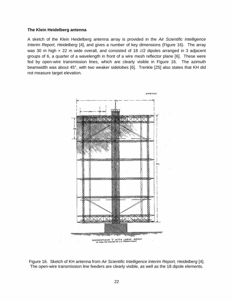
The Klein Heidelberg antenna
A sketch of the Klein Heidelberg antenna array is provided in the Air Scientific Intelligence
Interim Report, Heidelberg [4], and gives a number of key dimensions (Figure 16). The array
was 30 m high × 22 m wide overall, and consisted of 18 /2 dipoles arranged in 3 adjacent
groups of 6, a quarter of a wavelength in front of a wire mesh reflector plane [6]. These were
fed by open-wire transmission lines, which are clearly visible in Figure 16. The azimuth
beamwidth was about 45°, with two weaker sidelobes [6]. Trenkle [25] also states that KH did
not measure target elevation.
Figure 16. Sketch of KH antenna from Air Scientific Intelligence Interim Report, Heidelberg [4]. The open-wire transmission line feeders are clearly visible, as well as the 18 dipole elements.
23
The December 1944 interrogation report [5] stated that a KH antenna typically searched 100°
azimuth sectors, but contacts could be followed beyond these limits as far as possible unless
the operator received orders to the contrary. In any case „…It was forbidden to turn the aerial
through more than 360° in order to avoid placing undue strain on the cable connections.‟
Evidently, rotary joints were not used for these systems.
A fixed, modest gain antenna would have been needed to receive the direct signals from Chain
Home, to give the instant of transmission of each Chain Home pulse and trigger the KH display.
In the caption to a photograph of a Klein Heidelberg antenna, Trenkle [25] mentions a simple
synchronization antenna consisting of a horizontal dipole on a 15 m high wooden mast (or
tower), connected to the bunker via a balanced 2-lead screened HF cable. This Hilfsantenne
was located at a distance of 60 m from the main KH antenna [6].
The Klein Heidelberg receiving system and its operation
The second Vaudricourt P/W provided the following details about KH receivers and associated
equipment [5]9. Two identical receivers were located one above the other in the bunkers. The
upper receiver was attached to the KH antenna to receive target echoes; the lower, or „locking‟
receiver was attached to the auxiliary dipole to receive the CH direct path signal. Both receivers
had to be tuned to the frequency of a CH station, with each CH location and frequency
displayed on a map.
The heart of the KH receiving system was contained in a presentation unit known as the
Wächter Gerät, or Wächter Device after Dipl.-Ing Wächter (see earlier). This unit was a rather
primitive box about 80 cm high by 60 cm wide, and included two identical, side by side cathode
ray tubes (CRTs), about 12 cm in diameter, which were used for target range measurements in
a circular A-scope configuration. Bauer has identified this display tube as the magnetically-
deflected type LB13/40, and has reconstructed the likely form of the displays and circuitry and
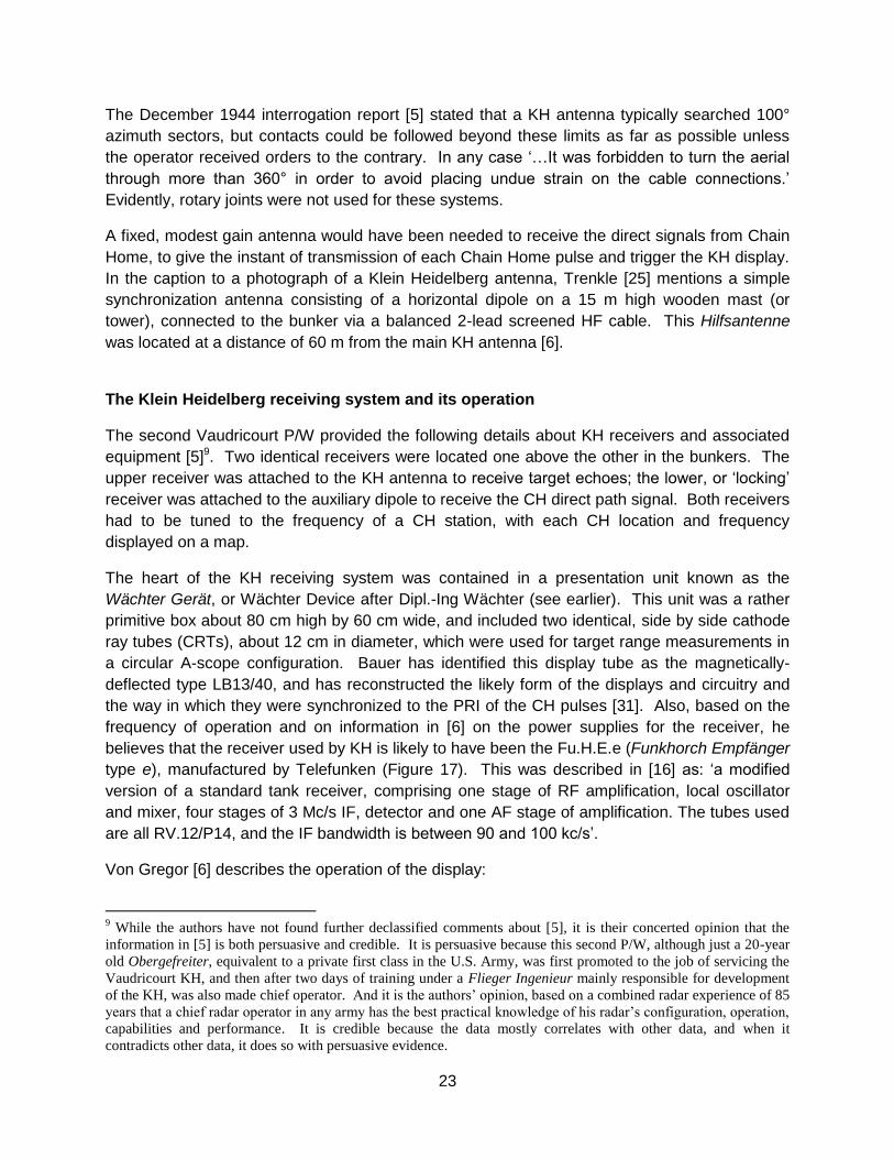
the way in which they were synchronized to the PRI of the CH pulses [31]. Also, based on the
frequency of operation and on information in [6] on the power supplies for the receiver, he
believes that the receiver used by KH is likely to have been the Fu.H.E.e (Funkhorch Empfänger
type e), manufactured by Telefunken (Figure 17). This was described in [16] as: „a modified
version of a standard tank receiver, comprising one stage of RF amplification, local oscillator
and mixer, four stages of 3 Mc/s IF, detector and one AF stage of amplification. The tubes used
are all RV.12/P14, and the IF bandwidth is between 90 and 100 kc/s‟.
Von Gregor [6] describes the operation of the display:
9 While the authors have not found further declassified comments about [5], it is their concerted opinion that the
information in [5] is both persuasive and credible. It is persuasive because this second P/W, although just a 20-year
old Obergefreiter, equivalent to a private first class in the U.S. Army, was first promoted to the job of servicing the
Vaudricourt KH, and then after two days of training under a Flieger Ingenieur mainly responsible for development
of the KH, was also made chief operator. And it is the authors‟ opinion, based on a combined radar experience of 85
years that a chief radar operator in any army has the best practical knowledge of his radar‟s configuration, operation,
capabilities and performance. It is credible because the data mostly correlates with other data, and when it
contradicts other data, it does so with persuasive evidence.
24
Figure 17. The Telefunken Fu.H.E.e (Funkhorch Empfänger type e) receiver which was used with the Klein Heidelberg radar. (photos: Arthur Bauer).
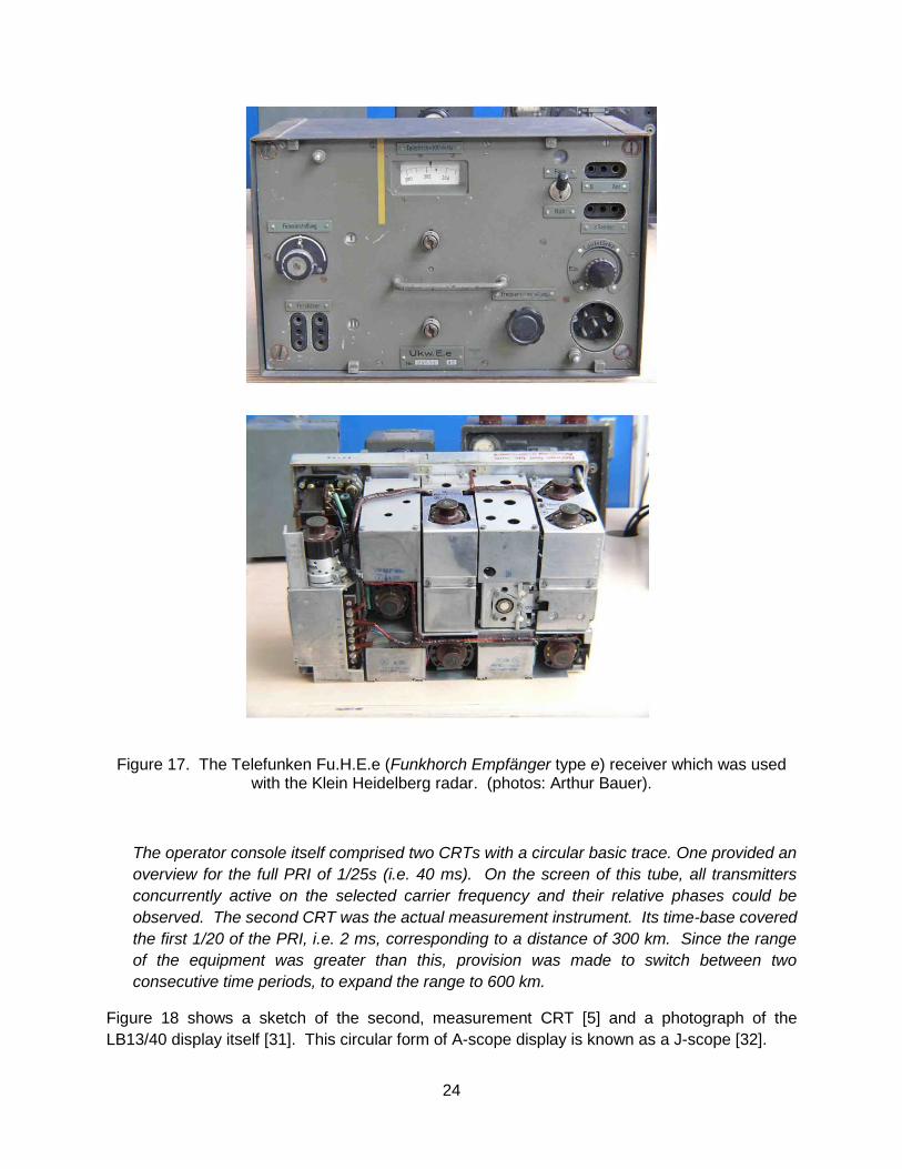
The operator console itself comprised two CRTs with a circular basic trace. One provided an
overview for the full PRI of 1/25s (i.e. 40 ms). On the screen of this tube, all transmitters
concurrently active on the selected carrier frequency and their relative phases could be
observed. The second CRT was the actual measurement instrument. Its time-base covered
the first 1/20 of the PRI, i.e. 2 ms, corresponding to a distance of 300 km. Since the range
of the equipment was greater than this, provision was made to switch between two
consecutive time periods, to expand the range to 600 km.
Figure 18 shows a sketch of the second, measurement CRT [5] and a photograph of the
LB13/40 display itself [31]. This circular form of A-scope display is known as a J-scope [32].

25
Figure 18. Sketch of the circular CRT display used by Klein Heidelberg [5] and the actual LB13/40 tube (Bauer [31]). The same display tube was used in the WÜRZBURG radar, where
the 0 – 40 scale corresponded to range in km.
This second Vaudricourt P/W [5] described in considerable detail how the measurements were
taken. Operators started with the left hand tube, which displayed blips from many CH
transmitters, all wandering “…round the tube, mostly in an anti-clockwise direction.” Then by
turning a knob marked „Stärke‟ (gain) on the D/F receiver only one wandering blip could be
displayed, which, when it reached zero, would be locked down with a coarse knob.
Then the operators shifted attention to the 20-times more sensitive right hand tube, which
displayed the same locked down blip near – but not necessarily on – its zero point. The
26
operator would then lock the blip to its zero point with a fine knob. The system was now
synchronized to a specific CH transmitter and ready for searching.
Once a target was detected, usually as a small blip a few mm above the circular trace, the
antenna was turned to maximize the blip amplitude. At this point a simultaneous azimuth (or
angle-of-arrival) and ellipse marker reading would be taken and then plotted on a 1:300,000
map for that specific CH station.
Forty concentric ellipses were drawn on the map, each with the CH and KH as their foci – one
ellipse for each of the 40 marks on the CRT. Thus intersection of the designated ellipse with the
azimuth angle drawn from the KH foci located the target. This data was then passed to the „A‟
Bunker by telephone – the normal aircraft-reporting grid. Figure 14 shows these ellipses, along
with the target location technique.
The P/W also reported problems with this process. First, target blips that were much broader
than those shown in Figure 18 could appear on the right hand scope, at times covering up to ten
range ellipse markers. At first, KH operators assumed they were seeing very large aircraft
formations, but this proved to be incorrect. It was then attributed to some form of unidentified
disturbance which, given the time of year (early summer) may well have been sporadic-E
propagation.
Second, the P/W reported that:
Once a contact had been obtained, the operator‟s greatest difficulty was to hold the blips
steady. It frequently happened that before a reading could be taken the zero blip, followed
by the target blip, would begin to wander round the tube; when this occurred, the operator
had to wait until the zero blip was back in the vertical position and locked again before he
could once more attempt to take a reading from the target blip. One of the main causes of
blips wandering was small variations of voltage. Attempts had been made to cure this by
means of a voltage regulator, but without success.
Third, he reported that:
When the target aircraft were in what P/W called the “dead” area directly between the British
transmitter and Vaudricourt, the Klein Heidelberg operator switched over to the second
British transmitter used. It took an efficient operator about 4/5 minutes to effect the switch-
over and be ready once more for operations.
This „dead‟ area is what we would now call the forward scatter region (Appendix C). In this
region the target RCS may be enhanced, but range and Doppler measurements are lost. Only
the target‟s location somewhere on the transmitter – receiver baseline, or direct path, is known.
WW2 French, Russian and Japanese forces exploited this phenomenon in trip-wire fences to
alert air defences about aircraft penetration of specific areas. Obviously KH, with its plethora of
available transmitters, could afford to ignore the limited data obtained from this region by shifting
to another transmitter – at a 4 to 5 minute penalty in down time.
27
Propagation effects
German radar scientists had been investigating the potential of HF radar since the autumn of
1941, and had begun to appreciate the peculiarities of radio propagation at these frequencies, in
particular finding that substantial ranges could be achieved by over-the-horizon propagation
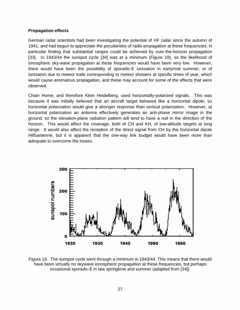
[33]. In 1943/44 the sunspot cycle [34] was at a minimum (Figure 19), so the likelihood of
ionospheric sky-wave propagation at these frequencies would have been very low. However,
there would have been the possibility of sporadic-E ionization in early/mid summer, or of
ionization due to meteor trails corresponding to meteor showers at specific times of year, which
would cause anomalous propagation, and these may account for some of the effects that were
observed.
Chain Home, and therefore Klein Heidelberg, used horizontally-polarized signals. This was
because it was initially believed that an aircraft target behaved like a horizontal dipole, so
horizontal polarization would give a stronger response than vertical polarization. However, at
horizontal polarization an antenna effectively generates an anti-phase mirror image in the
ground, so the elevation-plane radiation pattern will tend to have a null in the direction of the
horizon. This would affect the coverage, both of CH and KH, of low-altitude targets at long
range. It would also affect the reception of the direct signal from CH by the horizontal dipole
Hilfsantenne, but it is apparent that the one-way link budget would have been more than
adequate to overcome the losses.
Figure 19. The sunspot cycle went through a minimum in 1943/44. This means that there would have been virtually no skywave ionospheric propagation at these frequencies, but perhaps
occasional sporadic-E in late springtime and summer (adapted from [34]).

28
Klein Heidelberg deployment and operation
The second Vaudricourt P/W continued with deployment and operational details of the
Vaudricourt KH [5]. The KH antenna was erected on a Wassermann „chimney‟ in May 1944,
with the KH equipment (presentation screen, two …receivers, a locking unit and a power pack)
installed in the Wassermann bunker in mid-June 1944. However, a Wassermann radar was
never installed at this site, even though it was intended for use under „normal conditions‟, with
KH used …if the Wassermann were jammed or gave unsatisfactory results.
Examination of maps shows that the KH was installed at some distance from the other (active)
radars at the Stellung to reduce the effect of interference from them.
The KH was completed and underwent testing in June and July 1944, with operations starting
„in earnest‟ in August – and in the authors‟ opinion, a remarkably short time period for any new
radar deployment. Then on 27 August 1944 …orders were received to dismantle the KH at
Vaudricourt and to blow up the chimney and bunkers. So this KH was properly operational for
less than a month.
During this time KH successfully hitchhiked off two CH transmitters at bearings of 306 and 348
degrees from Vaudricourt, the two sites that gave the best view of air activity …between the
South of England and the battle area. The P/W reported that …the most distant contact which
he had measured with any success was at a range of 345 km [from KH], and …on average
between 300 and 350 km. The P/W also reported that the KH azimuth accuracy was ±10°.
The P/W then reported …instances in which the operator had obtained a contact and passed a
position through to the „A‟ bunker, only to be told a few minutes later that there were no aircraft
in the area concerned. Again this is not surprising, considering that this situation represents
one of the first attempts of multi-sensor target integration, and that such attempts using
displaced and disparate sensors have remained a vexing problem throughout the 20th century.
Sensor calibration, target registration and environmental conditions such a propagation,
multipath and masking continue to plague the process. However, had a Wasserman radar been
co-located with the KH, as was done in other sites, common target detection and location test
data could have been registered between the two – with likely better operational results. But it
was a good start.
5. KLEIN HEIDELBERG PERFORMANCE
Several reports indicate that the measured detection range of Klein Heidelberg was substantial.
Trenkle quotes a range „… mostly greater than 200 km, and on one occasion 398 km‟, a figure
which comes originally from Hoffmann‟s book [24]. Interrogation of the first P/W from
Vaudricourt [4], includes the statement „… the maximum range claimed each day was usually
about 450 km‟. In contrast, the second, Vaudricourt P/W reports average detection ranges
between 300 and 350 km. In all cases these observed ranges are quite impressive.
29
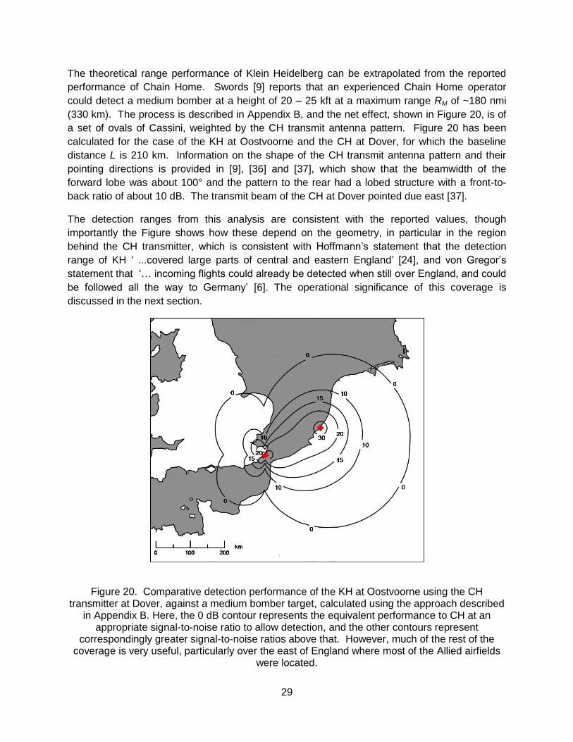
The theoretical range performance of Klein Heidelberg can be extrapolated from the reported
performance of Chain Home. Swords [9] reports that an experienced Chain Home operator
could detect a medium bomber at a height of 20 – 25 kft at a maximum range RM of ~180 nmi
(330 km). The process is described in Appendix B, and the net effect, shown in Figure 20, is of
a set of ovals of Cassini, weighted by the CH transmit antenna pattern. Figure 20 has been
calculated for the case of the KH at Oostvoorne and the CH at Dover, for which the baseline
distance L is 210 km. Information on the shape of the CH transmit antenna pattern and their
pointing directions is provided in [9], [36] and [37], which show that the beamwidth of the
forward lobe was about 100° and the pattern to the rear had a lobed structure with a front-to-
back ratio of about 10 dB. The transmit beam of the CH at Dover pointed due east [37].
The detection ranges from this analysis are consistent with the reported values, though
importantly the Figure shows how these depend on the geometry, in particular in the region
behind the CH transmitter, which is consistent with Hoffmann‟s statement that the detection
range of KH „ ...covered large parts of central and eastern England‟ [24], and von Gregor‟s
statement that „… incoming flights could already be detected when still over England, and could
be followed all the way to Germany‟ [6]. The operational significance of this coverage is
discussed in the next section.
Figure 20. Comparative detection performance of the KH at Oostvoorne using the CH transmitter at Dover, against a medium bomber target, calculated using the approach described
in Appendix B. Here, the 0 dB contour represents the equivalent performance to CH at an appropriate signal-to-noise ratio to allow detection, and the other contours represent
correspondingly greater signal-to-noise ratios above that. However, much of the rest of the coverage is very useful, particularly over the east of England where most of the Allied airfields
were located.

30
Trenkle [25] gives the range accuracy of Klein Heidelberg as around 1 – 2 km, and the angular
accuracy as around ±3º, later ±1º. Von Gregor [6] quotes a 5º accuracy, and states that a lobe-
switching modification was under development, but never reached practical deployment. In
contrast, the second Vaudricourt P/W reports [5] a KH azimuth accuracy of ±10°.
Appendix B also derives an expression for the way in which the spatial resolution of KH varies
as a function of target position, which is plotted in Figure 21. It can be seen that the bistatic cell
size is close to the monostatic cell size at longer ranges (R > ~1.5L) at any azimuth angle, and
whenever β is small, but becomes much larger whenever the target approaches the baseline
and R < L, corresponding to the „dead zone‟.
In assessing the angular accuracy (as distinct from resolution) of KH, for an antenna beamwidth
of 45° it is not apparent how the claimed accuracies of ±3° or 5º could have been achieved
without the use of modern lobe- or beam-splitting techniques. And ±1° appears beyond even
this capability. However the ±10° report appears reasonable, considering that the antenna was
manually rotated to maximize amplitude of the target return in a „peak picking‟ process, yielding
a 2:1 to a 3:1 improvement in accuracy over the nominal beamwidth, depending on the signal-
to-noise ratio.
Figure 21. Comparative resolution performance of KH with respect to that of CH, as a function
of target position on the bistatic plane.

31
6. OPERATIONAL SIGNIFICANCE OF KLEIN HEIDELBERG
First, consider KH coverage. As shown in Figures 3 and 7, the KH receive sites were situated
at baseline ranges, L, between 100 and 200 km from many of the cross-channel CH transmit
sites. Thus with a conservative estimate for KH‟s equivalent monostatic range, RM, of 330 km, a
single – but now distorted – oval of Cassini is generated, with average radius ~ 330 km,
surrounding each pair of CH / KH sites10. Thus coverage of one CH site would typically extend
from the English mainland down into the French and/or German mainland. Furthermore, with
judicious selection of the many CH transmitters located along the South and East coasts of
England, the net of six CH sites shown in Figure 7 could have generated contiguous and in
many cases overlapping coverage of all direct allied bomber routes to France and Germany.
Next, consider KH performance within its coverage region. Two sectors are of interest:
Forward Scatter and Bistatic. When an air target flies over the English Channel, three of the
southern KH sites in France must look northward, towards a CH transmitter to detect the target
(Figure 7). Thus the KH receiver must detect targets near the transmit-receive baseline where
the bistatic angle (defined in Figure 1) is large (approaching 180º). As outlined earlier, this
region is called the forward scatter sector, which at the frequencies used by CH (~30 MHz) and
for a typical aircraft target, is many tens of degrees wide. And as reported by the second
Vaudricourt P/W, operation was not attempted in this sector.
However, when the air target flies either a more northerly route, for example, over the lower end
of the North Sea, or enters the European mainland coastline at any point, these three KH sites
would now look in an easterly or southerly direction, away from the CH transmitters with much
smaller bistatic angles. Consequently, they operate in the bistatic sector where the accuracy of
target state estimates (bearing and range) begin to approach those of a monostatic radar. Thus
KH would operate with both an alerting and a cueing capability – that is, a full surveillance
capability – in these sectors.
Similar arguments apply to the three, more northern KH sites in Figure 7, but in near opposition
to the southern sites: no operation for targets over the lower end of the North Sea, where the
bistatic angles are large, but a full surveillance capability in the English Channel as well as
within the European mainland where the bistatic angles are small. Thus if netted, the six KH
sites could have provided near contiguous surveillance capabilities on air targets originating
from the English mainland, subject of course, to uncertainties of multipath mitigation and height
estimation.
This ex post facto analysis, coupled with the newly acquired, interrogation data, strongly
suggests that the Luftwaffe found KH to be a potentially useful adjunct to their Stellungen
operations, particularly as an un-jammed, covert air surveillance asset, and sited them
accordingly.
Now we come to the critical question of this paper: How well did KH work? In particular, was
there sufficient time between integration of KH into the German Kammhuber Line and
10
Oval distortion is due to the CH transmit antenna pattern used in the calculations.

32
destruction of the Kammhuber Line following the Allied invasion in 1944 to improve their air
defence operations? Little hard evidence is available to answer these questions. We know that
the KH site at Vaudricourt (SKORPION) was operational for less than a month – in August 1944
– before it was ordered dismantled. But what about the other five sites? The following sources
provide clues.
The first recorded indication that the Allies were aware of KH is the previously cited Air Scientific
Intelligence Interim Report, Heidelberg, dated 24 November 1944 [4] This intelligence was
discussed at a meeting at the Air Ministry in Whitehall on 27 December, and the minutes [38]
state that:
The Chairman asked A.D.I. (Science) to outline the information at present available. W/Cdr.
Cecil said that, according to prisoner of war reports, the system had worked, though a
certain amount of trouble had apparently been experienced in locking the receiver to the
C.H. pulses. The results achieved did not in general seem to be very accurate or reliable.
Despite these prisoner of war reports, there was no indication that the system had proved
satisfactory in operation, since the enemy had not been obtaining early warning of bomber
attacks....
The Chairman then asked D.D. of Radar 2 whether it was considered that the system was a
practical one. S/Ldr Blakemore replied that there were no technical difficulties, although we
had not ourselves attempted to use this method, since there were no suitable enemy
transmissions which we could use....
W/Cdr Burges said that in the main there was good reason so far to think that the enemy
was not obtaining any benefit from “Heidelburg” (sic), even if it were being used, since there
is no evidence of his being able to plot consistently though the “Mandrel” screen. There had
been a few instances of the enemy re-acting early to a raid, but in most cases a satisfactory
reason had been found other than the possibility of “Heidelburg”.
The meeting then discussed the potential danger that “Heidelburg” offered to our bomber
offensive, and agreed that the menace could be sufficiently great to warrant the immediate
consideration of countermeasures.
So, while the current utility of KH was assessed as marginal-to-nonexistent, with no indication of
improved air defence effectiveness that could not be attributed to other sources, its potential
was sufficient to warrant immediate attention.
Now the first P/W interrogation in the Air Scientific Intelligence Interim Report, Heidelberg is
dated 24 November 1944 [4], and by that date all but Stellung BIBER would have been in Allied
hands after the D-Day invasion. This document also states that the first KH at BULLDOGGE
was operational by August 1943, with the remainder in service by the end of 1943, which of
course conflicts with the start of KH Vaudricourt operation in August 1944, as reported by the
second P/W [5]. This is confirmed by von Gregor [6], who placed the date by which three of
them were operational six months later, by the summer of 1944. If so, it would only have been a
few weeks before most of the newly installed KH sites were overrun by the Allied advance
33
(Cherbourg was liberated on 27 June 1944, Ostend on 8 September and Boulogne on 22
September, but the Netherlands not till the end of the War).
Thus timing would explain why the enemy was not obtaining any benefit from KH: they simply
were not around long enough to do so. Compounding this problem are the cited P/W reports
that the KH at SKORPION suffered from accuracy and reliability problems. This in itself is not
unexpected considering that development of KH started in 1942, with deployment starting a
year or so later. Under such an exceedingly tight schedule, it is surprising that anything worked.
But the net result becomes a critical finding in itself.
Second is the curious unannounced inspection of the KH installation at Oostvoorne (BIBER) by
a mysterious Luftwaffe „Leutnant Künkel‟, whose papers were all in order but no-one seemed to
know about. An account of this visit is given in Hoffmann‟s book [24], quoting from the report of
Oberfeldwebel Schultze who was the Head of the KH base and equipment troop at BIBER. This
reports that during a tour of the site, Künkel stated he was tasked to have KH measure the
trajectories of the V-1 and V-2 rockets. The implication is that the KH at BIBER must have been
operating well enough to warrant such a request. Indeed, a post-war debriefing [39] reported
that KH …operators had seen rockets during the early part of their trajectory.
Subsequently it was suggested that Künkel may have been a British spy or from the Resistance
[11, 25, 40]. To add to this mystery, Phil Judkins has suggested that the infiltrator might have
been from one of the Communist networks rather than from London. Or that the Germans had
several competing internal security networks (RSHA11 versus Gestapo ….), and thus the
inspection was genuine, but the left hand did not know what the right hand was doing.
Whatever his affiliation, the details of his visit are the significant part of this story.
A third, truly impeccable source comes from R.V. Jones, who stated in a letter to Louis Brown
that Künkel was „not one of his men and that knowledge of Klein Heidelberg‟s function came
from the analysis of communications traffic‟ [11]. This statement is significant because, since
KH was otherwise silent, the communications traffic Jones was referring to must have contained
KH air target data passed up from third- and second-order Stellungen. And of course that
observation strongly implies that KH had entered some level of operational status.
A fourth source also surfaced at this time: a few weeks after the Künkel inspection the British
tried to put KH out of action by using „oscillator pulse-blocking [PRF jittering], but this effort was
unsuccessful‟ [40]. Although not stated, such knowledge must again have been gathered
through communications intercepts. Specifically, KH continued to send up useful air target data
even when CH employed oscillator pulse-blocking.
This finding was later confirmed by a statement by Oberstleutnant Hentz [39] that in October
1944 the British had started jittering the 25 Hz PRF of CH, …but in a very short time the
German engineers had developed a system for locking on automatically and Heidelberg was
able to continue working satisfactorily.
Reference [41] elaborated on this fix, which apparently was not as easy as first reported:
11
Reichssichersheithauptamt (Reich Security Head Office).
34
Until British C.H. stations began pulse-jittering this system [KH] worked very well. About six
months work was involved before jittering could be overcome and then, apparently not with
100% success. The solution had been to devise a discharge circuit which would allow the
time base to sweep only on receipt of a C.H. impulse. It was asked why such a circuit had
not been employed in the first instance to obtain efficient synchronization. Apparently it
hadn‟t occurred to them and had not been found necessary at first.
The authors observe that like most radar fixes, ECCM is not added until needed, and that its
need only occurs when effective ECM appears.
The fifth source [4] is the previously quoted statement by the first P/W from Vaudricourt
(SKORPION) that „…the maximum range each day was usually about 450 km‟. While the 450
km value is suspect, the key phrase is „each day,‟ showing that KH at SKORPION must have
been in or near full operation during August 1944, as reported by the second P/W. It is curious
that this rather astonishing quote was not assessed, or at least cited, during that Air Ministry
meeting in Whitehall on 27 December 1944.
Thus while the evidence is sparse and somewhat conflicting, it strongly suggests that KH
became operational at least at a few sites. To compound KH‟s timing problem, several KH sites
became the target of air attacks and were damaged, some while still under construction, and all
of the sites (not just those close to the Normandy beaches) continued under attack in the period
leading up to the D-Day invasion. In fact, reference [6] may even imply that BREMSE (Ostend),
AUERHAHN (Cap d‟Antifer) and TAUSENDFÜSSLER (Cherbourg) never reached full
operational status, and certainly pictures of the KH show substantial damage, evident in Figure
812. There would therefore have been very little opportunity – with the exception of the first site
at Boulogne (BULLDOGGE) and the one at Oostvoorne (BIBER) – for KH to improve air
defence operations, and this is illustrated by the red arrows marked in Figure 4. Thus the short
answer appears to be that KH arrived too late to be of much – if any – help.
Klein Heidelberg and the D-Day landings
It is interesting to consider the role of Klein Heidelberg in the D-Day landings (6 June 1944). A
map in Most Secret War [7] shows the disposition of radar stations along the north coast of
France (Figure 22). Of these, BULLDOGGE had had KH since late 1943, so would have been
fully operational. We know that the KH at SKORPION was not properly operational till August
1944. Those at AUERHAHN and TAUSENDFÜSSLER were under construction since early
1944. The Allies did not find out about KH till November 1944 [4], so were unaware of its
existence at the time of the D-Day landings.
A crucial part of the overall D-Day operation was the elaborate set of deceptions (OPERATION
FORTITUDE), intended to sow doubt in the minds of the Germans about the location and timing
of the invasion, and in particular feeding evidence to suggest that the invasion would be made
at the Pas de Calais or towards Fécamp/Cap d‟Antifer rather than Normandy. These
12
An account of the surrender by its commander, Major Friedrich Küppers, of the TAUSENDFÜSSLER Stellung on
27 June 1944 is provided in reference [41].

35
deceptions are detailed in [43], and were notably successful, to the extent that Field Marshal
von Rundstedt was reported to have remarked on 5 June 1944: „As yet there is no immediate
prospect of invasion.‟ A key part of the plan included Operations TAXABLE and GLIMMER,
which were two „spoof‟ invasions consisting of chaff dropped by aircraft flying tightly controlled
patterns, to give the effect to a radar of a large invading fleet moving at the appropriate rate.
These were augmented by „Filberts‟ (3 m radar corner reflectors inside Mk.IV balloons giving a
response equivalent to a 5,000 ton ship), equipment carried in launches to generate the
acoustic noise of an invasion force, as well as jamming, and spoof radio communications.
Figure 22. Map showing the disposition of German radar installations on the north coast of France at the time of the D-Day landings (adapted from Figure 23 of [7]). The deception
operations TAXABLE and GLIMMER would have had limited effect on the Klein Heidelberg receivers, had they been properly operational.
However, the chaff and jamming were aimed at the conventional FREYA, WASSERMANN and
MAMMUT radars which operated around 140 MHz, and WURZBURGs which operated around
560 MHz, and would not have been effective against KH ! In practice it is likely that most of the
radar stations would have been put out of action by bombing prior to D-Day (for example, it is
recorded that AUERHAHN was attacked on 11, 22, 23 and 30 May and 2 and 3 June 1944, and
much the same must have been true for the other radar stations in northern France. Having
said that, it would have been necessary for the Allies to leave some of the radar stations
operational in order for the deceptions to succeed, and maybe not all of the attacks were
intended to hit their targets).
36
But had KH been properly operational, TAXABLE and GLIMMER would not have been
anywhere near as effective. It is stretching things to claim that the whole course of history
would have been different, but it is another example that KH was just too late to make any
significant difference.
7. WHAT HAPPENED NEXT
Shortly after the 27 December 1944 Air Ministry meeting in Whitehall, which concluded that
KH‟s menace could be sufficiently great to warrant the immediate consideration of
countermeasures, Flt.Lt Silversides, a scientist from TRE, was sent to the Dutch/Belgian coast
at Knocke in January and February 1945 with a small team to carry out experiments to evaluate
the concept. He used a simple dipole antenna, a communications receiver and an oscilloscope,
and showed that it was quite straightforward to trigger the oscilloscope trace using the direct
pulses from the CH transmitter and to observe the echoes from aircraft targets in the form of an
A-scope display (Figure 23). His report [44] states:
At the range of the Dutch/Belgium coast, i.e. about 100 miles, the field strength of C.H.
pulses and their associated echoes is quite adequate to render the Heidelberg system
workable.
and
. . . Given reasonable D/F facilities it would be quite possible to plot tracks of aircraft at path
differences of up to 100 miles and probably up to path differences of 200 miles.
When the gain of the KH antenna (~ 20 dBi) is taken into account these ranges would be
significantly greater, by a factor of 2-3, in a similar way to the calculation in Appendix B.
The report goes on to suggest, in the light of these good results, that the technique might be
used to extend the coverage of CH, and gives some detail on how such a system might be
configured. It also reports the results of some limited experiments using the GEE
radionavigation signals13.
13 The Air Scientific Intelligence Interim Report, Heidelberg [4] had identified that signals from the GEE
radionavigation system would also be suitable, and a post-war interrogation of a German officer confirms that this
was indeed tried by the Germans, and that it was „quite successful, but was not used as there was no great point in
changing to a new system‟ [39]. There is also an intriguing comment in Trenkle‟s book that: „A similar device [to
KH] for using British radars in the 200 MHz band under the codename “Paris” was under development for the
Kreigsmarine, but the project was cancelled‟. In addition, there was a bistatic AI system called X-Halbe, which used
the illumination from a ground-based radar: X-Halbe lang (Freya, Wassermann, Mammut or Jagdschloss) or X-
Halbe kurz (Würzburg-Riese). By the end of the War one pre-production model of the X-Halbe had been completed
[48]. So Klein Heidelberg was by no means the only German WW2 bistatic radar system.

37
Figure 23. A-scope displays from the experiments of Flt.Lt Silversides [44], showing that it was relatively straightforward to trigger the display using the direct signals from CH and to detect
aircraft targets.
As well as the comments in [4] on countermeasures to KH, a meeting was convened at the Air
Ministry on 19 March 1945 to discuss what should be done [45]. Perhaps the most obvious
countermeasure is physical attack of the receive sites, as long as their locations are known, and
this was certainly done. Also, as already noted, from about October 1944 the PRFs of the CH
transmitters were deliberately jittered in order to make it more difficult for the KH receivers to
synchronize to the CH transmissions, and there is evidence that this was quite successful.
They also considered the possibility of switching off the CH transmissions altogether for a few
hours, under the codename BAFFLER. But it was pointed out that as well as interrupting the
operation of the air defence system, including the capability of detecting V-2 rockets (BIG BEN),
the air-sea rescue service depended on CH to locate and rescue downed aircrew. So it does
not seem that this was ever implemented. Finally, they also considered the use of repeater
jammers to generate multiple false targets. Such jammers (MOONSHINE) had already been
developed and used with success in the deception operations leading up to the D-Day landings,
mentioned above [43, 46].
Further experiments (Operation Heidelberg) were conducted by TRE scientists in April 1945 at
St Nic, to the south-west of Brest in Brittany, using the Downderry Chain Home station (in
Cornwall) as illuminator. The results were reported in a note dated 12 September 1945 [47],

38
which indicated some difficulties with triggering the direct signal from the transmitter, due to
radio frequency interference and possible sky wave interference with the ground wave, and
concluding that any redesign of CH would have to take into account the possibility of hostile
hitchhiking. This note concludes with:
As Headquarters 60 Group will be publishing a full report on the Heidelberg trials, no
attempt has been made to cover the work fully in the present note.
That full report has yet to be been found.
Nothing is left of the massive Klein Heidelberg antennas. Although the tubular steel
Wassermann-S towers were very robust, they were eventually pulled down and scrapped. A
description and some pictures of the demolition of the tower of the Klein Heidelberg at BIBER in
1948 appear in the book by Rijpsma and van Brakel [27], and are shown in Figure 15. But the
reinforced concrete L480 bunkers are, by their very nature, almost impossible to destroy, and
much of these remain at five out of six of the sites.
The latitudes and longitudes given in [4] can be plugged into Google Maps to reveal the
locations and satellite images of the Klein Heidelberg Stellungen. There are websites which are
devoted to WW2 bunkers of all types, with substantial galleries of photographs of the bunkers at
BIBER, SKORPION, AUERHAHN and TAUSENDFÜSSLER [42, 49–53]. Many of the sites are
heavily overgrown with vegetation. Some are not readily accessible to the public and are
surprisingly well preserved, with drawings and decorations still visible on the walls.
8. CONCLUSIONS AND LESSONS LEARNED
Klein Heidelberg was the world‟s first bistatic radar hitchhiker. And while many bistatic radar
fences preceded it into the field, KH can, quite properly, be viewed as the first bistatic radar in
the modern sense of radar‟s definition.
It may be useful to summarise KH‟s advantages and disadvantages as follows:
Advantages:
o Covert (electromagnetically and to some extent visually, when mounted on the back of an
existing WASSERMANN antenna)
o Very long detection ranges;
o Lower cost, size, weight and prime power than an equivalent monostatic radar, due to the
„free‟ transmitter and existing WASSERMANN towers and bunkers;
o Difficult to jam (since using same frequencies as CH) and not affected by WINDOW of
length corresponding to FREYA-type frequencies.

39
Disadvantages:
o Totally dependent on a hostile illumination source for operation.
o Poor range resolution for targets close to transmit-receive baseline (in the forward scatter
region), but which can be mitigated by appropriate choice of spatially-diverse transmitters.
We can conclude that Klein Heidelberg was a truly innovative approach to the increasing
effectiveness of Allied Radio Countermeasures, but was deployed too late to have had any
significant effect. It demonstrated the brilliance of the German radar scientists and engineers –
and for that matter the British ones in „cracking the covert KH code‟ once it was deployed.
And equally remarkable is the fact that Klein Heidelberg was developed and deployed – to the
point of achieving some useful level of performance – inside of two years. That feat becomes
even more extraordinary considering that it represents one half of a Chain Home radar, which
was developed under a massive, five-year program having highest priority. Thus Klein
Heidelberg probably received similar attention and funding during its short development cycle.
At this juncture, we must return to that fateful 1939 Graf Zeppelin airship flight up the North Sea,
which detected CH transmissions but misidentified them as radio-navigation aids. Had the
Germans correctly identified them as radar signals, and understood the potential of HF radar,
KH development could have started a year earlier, with a much greater chance of significantly
enhancing German air defences.
Thus we have another instance of Thomas Hobbes‟ dictum from „Leviathan‟:
Force, and fraud, are in war the two cardinal virtues.
And while the CH fraud was unintended, in the sense there was no attempt by the British to
disguise the CH transmissions, it was fraud nevertheless – with salutary results for Allied
bombing raids.
But the Allies did not follow KH up as assiduously as they should have after the end of the War.
Or if they did, it has not been possible to unearth the evidence. If they had, it might be expected
that they would have discovered (a) potential for own use of the hitchhiking technique with
various types of illumination, (b) how to detect hostile use of our own transmissions in this way
and (c) what to do about it in response. Thus, locating the full report from Headquarters 60
Group on the Heidelberg trials would be a productive step in this direction.
The lesson from this story is simple: These Klein Heidelberg bistatic hitchhikers were a
significant radar development during WW2, in terms of both alerting and cueing, clearly
exceeding that of simple, forward scatter fence alerting used by Japan, France and the USSR.
But they arrived too late to help German air defence surveillance. It would be another 25 years
before the concept was re-invented, now as Sugar Tree, a U.S. covert hitchhiker using Soviet,
surface-wave HF radio broadcast signals and a remote sky-wave receiver to detect Soviet
ballistic missile launches [3]. Thus it pays to heed history, because it does repeat itself.

40
9. ACKNOWLEDGEMENTS
We are profoundly grateful to many people who have provided information and pictures, helped
with translations, acted as a sounding-board for ideas and interpretations, and corrected our
mistakes. Our thanks are due to Arthur Bauer, Professor Ralph Benjamin, Alain Chazette, Dr
Joachim Ender, Dr Paul Howland, Dr Phil Judkins, Dr Wolfgang Koch, Pierre Novak, Professor
Hermann Rohling, Professor Ramsay Shearman, Rafael Smid, Col. Michaël Svejgaard, Dr Sean
Swords, Klaas van Brakel, Dr Piet van Genderen, Dr Aart van der Houwen, Jos Vogel,
Professor Roger Voles and Dr Matthias Weiss. Special thanks go to James Brown for plotting
Figures 20 and 21.
Care has been taken to try to contact and acknowledge all copyright holders of pictures that
have been used; if any are not sufficiently acknowledged we will be pleased to put this right in
future.
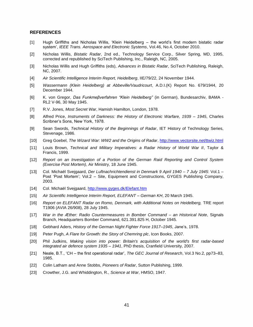
41
REFERENCES
[1] Hugh Griffiths and Nicholas Willis, „Klein Heidelberg – the world‟s first modern bistatic radar system‟, IEEE Trans. Aerospace and Electronic Systems, Vol.46, No.4, October 2010.
[2] Nicholas Willis, Bistatic Radar, 2nd ed., Technology Service Corp., Silver Spring, MD, 1995, corrected and republished by SciTech Publishing, Inc., Raleigh, NC, 2005.
[3] Nicholas Willis and Hugh Griffiths (eds), Advances in Bistatic Radar, SciTech Publishing, Raleigh, NC, 2007.
[4] Air Scientific Intelligence Interim Report, Heidelberg, IIE/79/22, 24 November 1944.
[5] Wassermann (Klein Heidelberg) at Abbeville/Vaudricourt, A.D.I.(K) Report No. 679/1944, 20 December 1944.
[6] K. von Gregor, Das Funkmeβverfahren “Klein Heidelberg” (in German), Bundesarchiv, BAMA - RL2 V-96, 30 May 1945.
[7] R.V. Jones, Most Secret War, Hamish Hamilton, London, 1978.
[8] Alfred Price, Instruments of Darkness: the History of Electronic Warfare, 1939 – 1945, Charles Scribner‟s Sons, New York, 1978.
[9] Sean Swords, Technical History of the Beginnings of Radar, IET History of Technology Series, Stevenage, 1986.
[10] Greg Goebel, The Wizard War: WW2 and the Origins of Radar, http://www.vectorsite.net/ttwiz.html
[11] Louis Brown, Technical and Military Imperatives: a Radar History of World War II, Taylor & Francis, 1999.
[12] Report on an Investigation of a Portion of the German Raid Reporting and Control System (Exercise Post Mortem), Air Ministry, 18 June 1945.
[13] Col. Michaël Svejgaard, Der Luftnachrichtendienst in Denmark 9 April 1940 – 7 July 1945: Vol.1 – Post „Post Mortem‟; Vol.2 – Site, Equipment and Constructions, GYGES Publishing Company, 2003.
[14] Col. Michaël Svejgaard, http://www.gyges.dk/Elefant.htm
[15] Air Scientific Intelligence Interim Report, ELEFANT – German KH, 20 March 1945.
[16] Report on ELEFANT Radar on Romo, Denmark, with Additional Notes on Heidelberg, TRE report T1906 (AVIA 26/908), 28 July 1945.
[17] War in the Æther: Radio Countermeasures in Bomber Command – an Historical Note, Signals Branch, Headquarters Bomber Command, 621.391.825 H, October 1945.
[18] Gebhard Aders, History of the German Night Fighter Force 1917–1945, Jane‟s, 1978.
[19] Peter Pugh, A Flare for Growth: the Story of Chemring plc, Icon Books, 2007.
[20] Phil Judkins, Making vision into power: Britain's acquisition of the world's first radar-based integrated air defence system 1935 – 1941, PhD thesis, Cranfield University, 2007.
[21] Neale, B.T., „CH – the first operational radar‟, The GEC Journal of Research, Vol.3 No.2, pp73–83, 1985.
[22] Colin Latham and Anne Stobbs, Pioneers of Radar, Sutton Publishing, 1999.
[23] Crowther, J.G. and Whiddington, R., Science at War, HMSO, 1947.

42
[24] Karl-Otto Hoffmann, Ln-Die Geschichte der Luftnachrichtentruppe, Band I/II, (in German), Kurt Vowinckel Verlag, Neckargemünd, 1965.
[25] Fritz Trenkle, Die Deutschen Funkmeßverfahren bis 1945, (in German), Motorbuch-Verlag, Stuttgart, 1979.
[26] Col. Michaël Svejgaard, http://www.gyges.dk/Klein%20Heidelberg.htm
[27] Jeroen Rijpsma and Klaas van Brakel, Radarstellung BIBER: Kustverdediging op Voorne 1940 – 1945, (in Dutch), 2005.
[28] Hans H. Jucker, „Some historical aspects of HF radars‟, http://www.cdvandt.org, 2004.
[29] Alain Chazette, Alain Destouches and Bernard Paich, Atlantikwall; le Mur de L'Atlantique en France 1940-1944, Heimdal, Bayeux, 1995, ISBN: 2840480883 / 2-84048-088-3.
[30] Conseil Régional de Basse-Normandie / National Archives USA, http://www.archivesnormandie39-45.org/
[31] Arthur Bauer, http://www.cdvandt.org/k-h.htm
[32] IEEE Standard Radar Definitions, IEEE Std 686–200814
.
[33] James M. Headrick and Stuart J. Anderson, „HF Over-The-Horizon Radar‟, Chapter 20 in Radar Handbook (third edition), M.I. Skolnik (ed.), McGraw-Hill, 2008.
[34] http://solarscience.msfc.nasa.gov/images/zurich.gif
[35] Jackson, M.C., „The geometry of bistatic radar systems‟, IEE Proc., Vol.133, Part F., No.7, pp604-612, December 1986.
[36] TNA/PRO AIR 10/3758, p5.
[37] Michael Bragg, RDF 1, Hawkshead Publishing, 2002.
[38] Minutes of a meeting held in Room 2/3 Air Ministry, Whitehall, at 1030 on Wednesday, 27th December 1944, to discuss “Heidelburg”.
[39] Interrogation of Oberstleutnant Hentz, AVIA 39/40: AL no 62, sheet 4, 14.2.46.
[40] David Pritchard, The Radar War: Germany‟s Pioneering Achievement, 1904–1945, Patrick Stephens Ltd., Cambridge, 1989.
[41] AVIA 39/41, A.L. No.28, sheet 11, 23.10.45.
[42] http://batteries.du.cotentin.perso.sfr.fr/osteck.htm
[43] Russell W. Burns, „Deception, technology and the D-Day invasion‟, IEE Science and Education Journal, pp81-88, April 1995.
[44] Flt Lt R.G. Silversides, Interim Report on Heidelberg Investigations Carried Out on the Belgium Coast between 24.1.45 & 10.2.45, 17 February 1945.
[45] Minutes of a meeting held at the Air Ministry, Whitehall on 19th March 1945 to discuss the implementation of counter-measures to Heidelberg, CMS. 717/R.1(a).
[46] The Production of False Reponses to the Enemy R.D.F. System, Letter from A.O.C.-in-C.F.C., AVIA 7/1544, 12 September 1941.
[47] Attree, V., Report on a Visit to 191 A.I.L.E.S. St Nic, France, 12 September 1945.
[48] http://www.gyges.dk/lichtfug_223.htm
[49] http://www.bunkerpictures.nl/datasheets/holland/datasheet-oostvoorne-bpt102.html
[50] http://www.vanderweel.info/atlantikwall/today_nl_oost-voorne.htm
14
The Panel that revised this IEEE Standard in 2008 was chaired by one of the authors of this paper.
43
[51] http://www.bunkerpictures.nl/
[52] http://www.bunkerpictures.nl/datasheets/france/seine-maritime/datasheet-capdantifer.html
[53] http://www.atlantikwall.co.uk/atlantikwall/france/osteck01/html/page01.htm
[54] Letter from Chief Superintendent, TRE, D.5454/WEJF/2435, 27 March 1945.
[55] Col. Michaël Svejgaard, http://www.gyges.dk/
Documents [4], [5], [12], [15], [16], [17], [36], [38], [39], [41], [44], [45], [46], [47] and [54] are held by the British Public Records Office, Kew, in south-west London.

44
Appendix A: ELEFANT and SEE-ELEFANT
The ELEFANT and SEE–ELEFANT radars were introduced in Section 2. ELEFANT was large,
high-power (380 kW peak transmit power), operating over the band 20 – 40 MHz, a low (25 Hz)
pulse repetition frequency, quasi-bistatic with the transmitter and receiver separated by a short
distance, and with floodlight transmitter illumination over a 120° arc – so in many respects
similar to Chain Home. In fact, it has been suggested that one reason for building these
systems was to emulate the CH radars, in order to measure first hand their performance and
possible vulnerabilities. Such a practice continued throughout the Cold War.
Only a small number were built; amongst these one was located in the Netherlands (Stellung
MAX) and one at Rømø (an island off the west coast of Denmark – Stellung ROBBE NORD)15.
Figure 24 shows the ELEFANT at MAX, and Figure 25 shows the SEE-ELEFANT at Rømø.
The radar operator crew of the ELEFANT in the Netherlands were moved to Rømø in
September 1944, as the Allies approached following the D-Day invasion and the Arnhem raid
(17-21 September 1944), and the equipment brought back to Germany [25]. According to
Trenkle [25] one was also under construction in Norddeich but was destroyed by a storm surge.
Svejgaard confirms that there was a partly-completed SEE–ELEFANT/RÜSSEL at Hjertebjerg
(Hanstholm) in the north of Denmark, and has located some of the antenna foundations [13].
SEE–ELEFANT was installed at Rømø in late 1944 as part of the German air defence system in
Denmark. Its configuration was rather unusual: it consisted of a transmitter/receiver with a
broad beamwidth, known as KOPFE (elephant‟s head). The antenna consisted of separate
transmit and receive arrays, side by side, mounted between two 100 m high towers which dwarf
the MAMMUT radar immediately underneath, and provided beams pointing both to the west and
to the east. The broad beamwidth meant that this system was only able to provide range
information. An L485 bunker housed the equipment and crew both for the MAMMUT and SEE-
ELEFANT radars. A separate receive-only antenna, about 1.5 km away, was known as
RÜSSEL (elephant‟s trunk), and functioned in the same way as the antenna of KH, as a
rotatable array providing direction-of-arrival information. A landline link between KOPFE and
RÜSSEL gave the instant of transmission of each pulse to synchronize the display, and Bauer
has found that the receiver and display were identical to those of KH.
It is evident, therefore, that SEE-ELEFANT also had a KH-type mode of operation in which it
could make use of CH transmissions. This was not in use during OPERATION POST
MORTEM, and it is unclear whether it could actually have worked in practice. A letter from
Chief Superintendent, TRE [54] dated 27 March 1945 concludes, both on the basis of
Silversides‟ measurements of Chain Home signal strength at Knocke on the Belgian coast [44]
and on calculations, that the direct signal from Chain Home (Bawdsey), which would have been
necessary for synchronization, would have been far too weak, and hence dismisses the
possibility.
15
According to Hoffman [24] another ELEFANT was built at Warna, Romania, with four systems arranged in a
square to cover 360˚. Pritchard [40] states that an ELEFANT was installed at Jan Mayen Island, in the Arctic to the
north of Iceland between Norway and Greenland, in August 1944, but this is certainly wrong, and probably a
mistranslation on his part of the information from the books of Hoffmann and Trenkle.

45
Figure 24. The ELEFANT radar at Stellung MAX (Castricum) in the Netherlands (pictures from
Klaas van Brakel).
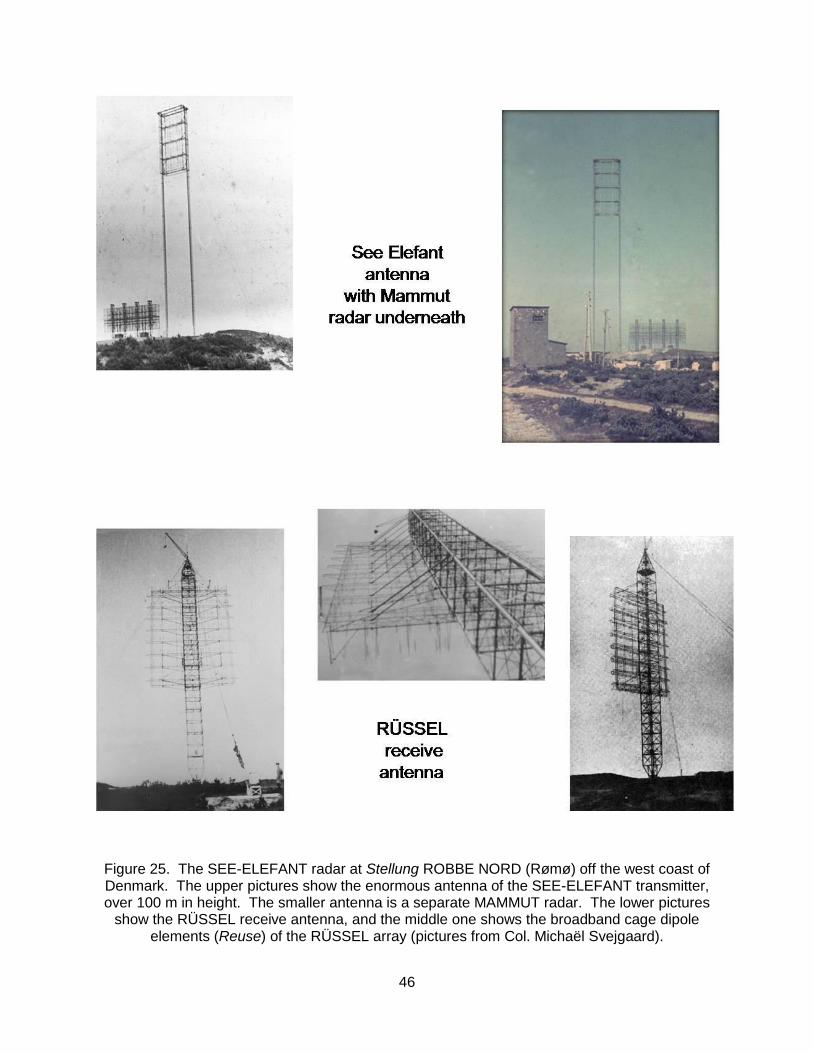
46
Figure 25. The SEE-ELEFANT radar at Stellung ROBBE NORD (Rømø) off the west coast of Denmark. The upper pictures show the enormous antenna of the SEE-ELEFANT transmitter, over 100 m in height. The smaller antenna is a separate MAMMUT radar. The lower pictures
show the RÜSSEL receive antenna, and the middle one shows the broadband cage dipole elements (Reuse) of the RÜSSEL array (pictures from Col. Michaël Svejgaard).
47
For comparison, the range from a Chain Home station on the south coast of England to the
north coast of France is of order 100 km; from Bawdsey Chain Home station to Rømø is nearly
600 km. Furthermore, at the mid-point between the Chain Home transmitter and the Klein
Heidelberg receiver an aircraft target would have to be at an altitude of 5.3 km (17,200 feet) to
be line of sight to both (making the simplifying assumption that both transmitter and receiver are
at sea level, and making the usual 4/3 Earth radius assumption to account for the fall-off of
atmospheric refractive index with height), and even higher elsewhere.
We can imagine that SEE-ELEFANT might have been intended to operate with other co-
operative sources. The radar engineers responsible for SEE-ELEFANT would have been aware
of the success of KH, but would surely have realized that its major weakness was that it
depended fundamentally on a source (CH) that was under control of the enemy. It would have
been natural to have explored the use of other sources such as other ELEFANT transmitters.
Trenkle states that SEE–ELEFANT was used to track V-2 rockets and to pinpoint their strikes
on London, at ranges of order 800 km, but the accuracy, both in range and azimuth, would have
been poor. However, Svejgaard states that it was of significant value in the air defence role
since it was unaffected by WINDOW cut to the wavelength of the higher-frequency German
radars, and the report on Exercise POST MORTEM [12] confirms that much useful information
was obtained from the SEE-ELEFANT throughout the Exercises, and that it was virtually
unaffected by MANDREL jamming or by WINDOW. Svejgaard has published detailed maps of
the locations of the SEE–ELEFANT and RÜSSEL, as well as of all other Stellungen in Denmark,
with photographs of the radars themselves and of what is left today of the antenna mountings
and the bunkers [13].
The ELEFANT and RÜSSEL antennas were superficially similar to those of KH, but the
ELEFANT antenna had 18 (three sets of six) simple half-wave dipole elements as did the KH
antenna, while the RÜSSEL antenna had 32 elements, described in [10] as „an array of broad
band dipoles arranged in four bays stacked eight high with dipole reflectors behind, and
supported on a single mast 220 feet high‟. The photograph of the RÜSSEL array in Figure 25
shows that the elements were broadband cage-type dipoles16. The ELEFANT receive antenna
was mounted on a WASSERMANN-M4 tower, which had an open lattice construction; the KH
antenna was on a WASSERMANN-S whose tower was a single tubular structure. So the
misidentification of ELEFANT and SEE-ELEFANT/ RÜSSEL as KH is understandable,
especially if made on the basis of aerial reconnaissance photographs which may not have been
perfectly clear, and with the benefit of hindsight the identification was not in fact very wide of the
mark.
Our conclusion is that the ELEFANT and SEE-ELEFANT radars were experimental, perhaps
conceived in imitation of CH, and intended for several purposes – but inspired by the same
thinking that led to KH, in other words a recognition that the German early warning radar was
potentially severely affected by Allied countermeasures. The several purposes were: (i) air
defence, in the same way as CH; (ii) tracking of V-2 rockets; and (iii) for bistatic experiments,
16
The German term for this type of element is Reuse, which translate literally as „lobster pot‟.

48
either using CH transmissions (non-cooperative, in the same way as KH), or perhaps
transmissions from other ELEFANTs (co-operative).
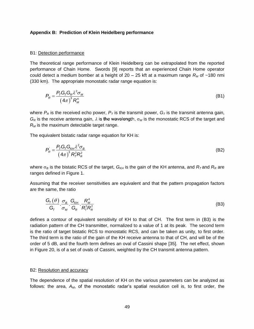
49
Appendix B: Prediction of Klein Heidelberg performance
B1: Detection performance
The theoretical range performance of Klein Heidelberg can be extrapolated from the reported
performance of Chain Home. Swords [9] reports that an experienced Chain Home operator
could detect a medium bomber at a height of 20 – 25 kft at a maximum range RM of ~180 nmi
(330 km). The appropriate monostatic radar range equation is:
T T R M
R
M
P G GP
R
2
3 44 (B1)
where PR is the received echo power, PT is the transmit power, GT is the transmit antenna gain,
GR is the receive antenna gain, M is the monostatic RCS of the target and
RM is the maximum detectable target range.
The equivalent bistatic radar range equation for KH is:
' T T KH B
R
T R
P G GP
R R
2
3 2 24 (B2)
where B is the bistatic RCS of the target, GKH is the gain of the KH antenna, and RT and RR are
ranges defined in Figure 1.
Assuming that the receiver sensitivities are equivalent and that the pattern propagation factors
are the same, the ratio
. . .
T B KH M
T M R T R
G G R
G G R R
4
2 2 (B3)
defines a contour of equivalent sensitivity of KH to that of CH. The first term in (B3) is the
radiation pattern of the CH transmitter, normalized to a value of 1 at its peak. The second term
is the ratio of target bistatic RCS to monostatic RCS, and can be taken as unity, to first order.
The third term is the ratio of the gain of the KH receive antenna to that of CH, and will be of the
order of 5 dB, and the fourth term defines an oval of Cassini shape [35]. The net effect, shown
in Figure 20, is of a set of ovals of Cassini, weighted by the CH transmit antenna pattern.
B2: Resolution and accuracy
The dependence of the spatial resolution of KH on the various parameters can be analyzed as
follows: the area, AM, of the monostatic radar‟s spatial resolution cell is, to first order, the

50
product of the cross-range width of the beam at the target and the thickness of the annulus
defining its range resolution:
2
M
cA Rsin
2 (B4)
where c is the speed of propagation, is the pulse length and 2 is the two-way –3 dB
beamwidth of the monostatic radar.
Similarly, the area, AB, of the bistatic radar‟s spatial resolution cell is the product of the cross-
range width of the receiver beam at the target and the thickness of its annulus:
1
B R
cA Rcos sin
2 2 (B5)
where is the bistatic angle defined in Figure 1, RR is the target-to-receiver range and 1 is the
one-way –3 dB beamwidth of the bistatic receive antenna.
The normalized performance of the bistatic receiver with respect to the comparable monostatic
radar is then:
1 2
B
M
A
A
sin sin
cos 2 (B6)
Note that sinΘ1 > sinΘ2 and cos(β/2) ≤ 1, so that AB > AM for all β.
Figure 21 plots equation (B6) as a function of target location on the bistatic plane. The bistatic
cell size is close to the monostatic cell size at longer ranges (R > ~1.5L) at any azimuth angle,
and whenever β is small. AB/AM becomes much larger whenever the target approaches the
baseline and R < L, as expected.
For the issue at hand, determining degradation of the geometric contribution to positioning
accuracy of KH with respect to CH as measured by their relative spatial resolution cell sizes, we
note that since CH used separate antennas for transmit and receive, with the CH receive
antenna directivity no greater than KH directivity, the sinΘ1 / sinΘ2 scaling factor ~ 1. These
findings suggest a KH positioning accuracy performance matching that of CH over most of its
surveillance region.

51
Appendix C: FORWARD SCATTER
When a target lies on the transmitter-receiver baseline, its RCS is governed not by its
backscattering properties but by its physical cross-sectional area. This can be understood from
Babinet‟s Principle from physical optics, which states that the diffracted field around an object is
equal and opposite to that from a target-shaped hole in an infinite screen – since the two fields
must add to zero. Specifically, if the silhouette area of the target is A, the forward scatter RCS
B is given by:
4
B
A2
2 (C1)
and the angular width of the scatter (in radians) is approximately:
B
d (C2)
where d is the linear dimension of the target in the appropriate plane.
Figure 26 plots these, as a function of frequency, for a typical WW2 heavy bomber with A = 20
m2, d = 30 m. The forward scatter RCS at 30 MHz is actually slightly lower than the monostatic
RCS, which might be of the order of 100 m2 since the target is in the resonance part of the RCS-
vs-frequency characteristic. The angular width of the forward scatter is of order 20°. This is in
marked contrast to the effect at microwave frequencies, where the forward scatter RCS may be
several tens of dB higher than the monostatic RCS, though over a narrower angular width.
The forward scatter geometry gives no range information, since the scattered signal reaches the
receiver at the same time as the direct signal, irrespective of where the target is located on the
transmitter-receiver baseline.
Figure 26. Plot of forward scatter RCS B (RHS) and angular width B of forward scatter (LHS) for a typical heavy bomber target with silhouette area A = 20 m2 and linear dimension d = 30 m.

52
Appendix D: Sources of information on Klein Heidelberg
Contemporary documents on Klein Heidelberg are somewhat scarce, at least partly because
such information was highly classified, by both the Allies and the Germans. Yet such
information is often of most use because it gives an accurate, first-hand picture of what was
known, or at least believed, at the time. Even with information of this kind, though, there are
occasional inconsistencies.
The most useful documents of this kind are the Air Scientific Intelligence Interim Report,
Heidelberg [4], the report on the interrogation of a second prisoner-of-war radar operator from
SKORPION [5], and the subsequent notes and minutes of meetings; these documents are held
in the British Public Records Office at Kew. A document held in the German Bundesarchiv [6]
gives the German side of the story, with detailed information not available in any other sources.
This is a two-page note, dated 30 May 1945 – i.e. about 3 weeks after the end of the War, which
at first sight seems strange – and written by Fl.Ob.Ing K. von Gregor (Fl.Ob.Ing = Flug Ober
Ingenieur = Air Chief Engineer) at Grauel (which may have been a prisoner-of-war camp) in
Schleswig-Holstein in northern Germany. It seems that this was an attempt by a senior
engineering officer, in all of the uncertainty that must have surrounded the end of the War, to
record information that might otherwise be lost, essentially for professional reasons. This is
perhaps understandable, and certainly most laudable. So Fl.Ob.Ing von Gregor receives our
commendation for services to the history of bistatic radar.
The report of the interrogation of the second prisoner-of-war radar operator from SKORPION [5]
gives substantial detail on the way that KH was used, sketches of the antenna and the
equipment, the dates by which it was installed and by which it was operational, and ultimately
destroyed in the face of the Allied advance.
It should be appreciated that the information discussed in the various Air Ministry meetings at
the end of 1944 and beginning of 1945 [38, 45] had come from the interrogation of the two P/Ws
from SKORPION (Vaudricourt), which, as we have seen, was in the process of being
commissioned in something of a rush, and which was experiencing some problems. The
meetings were not aware of the status or performance of the KHs at BULLDOGGE or BIBER
(which were commissioned earlier and worked rather better), and this would have given them a
misleading picture of the overall capability of KH.
Several books, including those by Hoffmann and Trenkle (in German) [24, 25], and
subsequently by Pritchard, Price and Brown (in English) [40, 8, 11] give short descriptions of
KH, and some include photographs. The book by Rijpsma and van Brakel (in Dutch) on the
BIBER Stellung [27] has a description and several photographs of KH, including some of the
demolition of the WASSERMANN tower in 1948 (Figure 15). Arthur Bauer has produced a
detailed description of the receiver and display equipment used by KH and the means by which
the synchronization to the direct CH pulses was achieved [31]. Finally, the extensive and
detailed GYGES website maintained by Col. Michaël Svejgaard [55] includes a section on Klein
Heidelberg, based on the information contained in [4].