a coherent processor for bistatic synthetic aperture...
TRANSCRIPT

A Coherent Processor for Bistatic Synthetic Aperture Radar
Authors: Craig Williams, Martin St-Hilaire and Ron Saper March 2003
Vantage Point International Inc. 1704 Carling Avenue 2nd floor
Ottawa, Ontario, K2A 1C7 Tel: 613-798-2244
www.vantpoint.com
Contract # W7714-020667/001/SV Prepared for: Dr. James Tunaley Defence R&D Canada – Ottawa
3701 Carling Ave., Ottawa, Ontario, K1A 0Z4 The scientific or technical validity of this Contract Report is entirely the responsibility of the contractor and the contents do not necessarily have the approval or endorsement of Defence R&D Canada.
© Her Majesty the Queen as represented by the Minister of National Defence, 2003
© Sa majesté la reine, représentée par le ministre de la Défense nationale, 2003

A Coherent Processor for Bistatic SAR ii
Vantage Point International Inc. March 2003
EXECUTIVE SUMMARY
This report documents work undertaken to build, test and run a Bistatic SAR Processor. The processor was successfully built and used to process bistatic experimental data collected in early 2002 during joint US-Canada bistatic radar experiments. A relatively sophisticated Bistatic SAR Processor was successfully developed in Microsoft Visual C++ 6.0 under Windows 2000. The processor handles alignment of the data using the direct path data, automatic estimation of the receiver beam center crossing time (BCC), range compression of the reflected path data, and phase history compression of the reflected path data. The results show that the data contain useful bistatic information that can be processed to produce clutter maps that seem to agree with expectations in many aspects. Specifically we see evidence of resolution similar to that expected, some structure along bistatic range contours, and occasional bright returns. That being said, the image quality falls short of that expected for mono-static SAR images. This is likely due at least in part to the fact that the experimental geometry limits the image quality because the contours of constant bistatic range and the contours of constant bistatic Doppler are nearly parallel within the receive antenna footprint. This leads to streaks in the image which correspond to elongated ground patches which are collapsed into single resolution cells in bistatic range/Doppler space. Another factor limiting image quality is that the experimental geometry limits resolution in the bistatic range direction because the receive antenna is pointed towards the illuminator instead of away from the illuminator, leading to reduced resolution across bistatic range. Judging from the contour spacing, resolution is 3-4 times coarser than it would be for a better antenna pointing geometry, and features in the clutter map seem to confirm this. It should be noted that the Bistatic SAR Processor is a completely new development and the algorithms and code incorporated into it are mostly first generation. Notably the methods for detecting the tower BCC, estimating ground point BCC, and dealing with missing pulses need to be refined. More work is required to improve algorithms used in the Bistatic SAR Processor and also to test it on further existing data sets as well as future data sets with more favorable receive antenna pointing geometry. This further work will help determine to what extent algorithm limitations and receive antenna pointing geometry are limiting image quality.

A Coherent Processor for Bistatic SAR iii
Vantage Point International Inc. March 2003
Table of Contents 1 Introduction................................................................................................................ 1
1.1 Background .................................................................................................................... 1 1.2 Objectives and Scope ..................................................................................................... 2 1.3 Summary of Project Outcome........................................................................................ 3
2 Analysis of Experimental Data.................................................................................. 4 2.1 Summary of Data Sets.................................................................................................... 4 2.2 Analysis of Bistatic Geometry ....................................................................................... 5 2.3 Direct Path Pulse Compression and Data Registration .................................................. 7 2.4 Validation of Measured and Modeled Direct Path Phase .............................................. 8 2.5 Clutter Map Processing................................................................................................ 12 2.6 Structure of Results CD-ROM..................................................................................... 16
3 User’s Guide............................................................................................................. 18 3.1 Installation.................................................................................................................... 18 3.2 Overview of Bistatic Processing Steps ........................................................................ 18 3.3 The Five Required Input Files ..................................................................................... 19 3.4 Specifying Files and Processing Parameters in the Bistatic Processor ........................ 21 3.5 Processing the Direct Path Data................................................................................... 23 3.6 Processing the Reflected Path Data.............................................................................. 24 3.7 Processing the Ground Return to a Clutter Map .......................................................... 25
4 Programmer’s Guide................................................................................................ 27 4.1 Application Overview .................................................................................................. 27 4.2 Building the Bistatic Processor from the Source Code ................................................ 27 4.3 Program Flow & Algorithm Description ..................................................................... 28 4.4 Bistatic Library ............................................................................................................ 33 4.5 User Interface............................................................................................................... 36
5 Discussion, Conclusions and Recommendations ................................................... 37 5.1 Discussion .................................................................................................................... 37 5.2 Conclusions.................................................................................................................. 38 5.3 Limitations and Recommendations for Future Work................................................... 38
6 References ................................................................................................................ 39
Appendix A: Experimental Results for 28 January 2003.............................................. 40
Appendix B: Experimental Results for 16 May 2003 .................................................... 50
Appendix C: Experimental Results for 28 May 2003 .................................................... 59
A Coherent Processor for Bistatic SAR iv
Vantage Point International Inc. March 2003
Appendix D: Listing of rangeCompressAndRegister Function......................... 69
Appendix E: Listing of RangeCompress Function ................................................... 72
Appendix F: Listing of extractPulses Function ................................................... 73
Appendix G: Listing of computeGroundReturn Function..................................... 75 List of Figures Figure 1 – Bistatic range and Doppler contours for the 28 January 2002 trial.------------6 Figure 2 – Bistatic range and Doppler contours for the 16 May 2002 trial. ----------------7 Figure 3 – Range compressed & aligned reflected path, 28 May 2002, Channel 4. -------8 Figure 4 – Simulated phase history at the tower as calculated by the Bistatic Planner.---9 Figure 5 – Simulated phase history at the receiving tower – linear phase removed.----- 10 Figure 6 – Measured direct path phase history, 28 January 2002. ------------------------- 11 Figure 7 – Phase history at the tower as calculated by the Bistatic SAR Processor.----- 12 Figure 8 – Simulated effect of linear phase on compression of phase history. ------------ 13 Figure 9 – Observed effect of linear phase offset on maximum image intensity.---------- 14 Figure 10 – Clutter map generated from full aperture data, 28 January 2002.----------- 15 Figure 11 – Directory structure for results on CD-ROM. ----------------------------------- 16 Figure 12 - In-phase and Quadrature filters--------------------------------------------------- 31 Figure 13 - Bistatic Scenario Classes ---------------------------------------------------------- 34 Figure 14 - Bistatic Data Processing Classes ------------------------------------------------- 35 _Toc37648012

A Coherent Processor for Bistatic SAR 1
Vantage Point International Inc. March 2003
1 Introduction Defence Research & Development Canada – Ottawa (DRDC-O) is participating in a Joint Experiment with the Air Force Research Laboratory in Rome, New York. The objective of this study is to understand bistatic radar and bistatic clutter statistics, and to investigate processing methods with the ultimate aim of detecting airborne targets. Part of the Joint Experiment is an on-going series of trials which produced several data sets including the three used in this report. Based on experience gained from previous work on a bistatic radar planning tool for the experiments in question, Vantage Point International Inc was contracted by DRDC-O to develop a coherent processor suitable for use with experimental data collected in Rome in 2002. The data is from an experiment where RADARSAT-1 is the illuminator, and the receive antennas are atop a stationary tower. One receive antenna captures the direct path, while a receive antenna array is pointed at the terrain to capture reflected energy collected by the full physical aperture and three of eight physical sub-apertures. The primary objective of the work is to create a Bistatic SAR Processor software package using Microsoft Visual C++ under Windows 2000 and to produce clutter maps for trials on three different experiment dates. In addition, a technical report must be generated that describes the software, its algorithms, mode of use, and the results obtained to date. The current report is provided to satisfy the technical reporting requirement of the contract. Section 1 covers the background, scope and objectives, and provides an overview of the outcome of the project. Section 2 provides an analysis of the experimental data. Section 3 is a user’s guide for the Bistatic SAR Processor, while section 4 is the programmer’s guide. Section 5 contains discussion, conclusions and recommendations. The appendices show the full set of results and listings for four key software functions.
1.1 Background Prior to the start of this project, Dr James Tunaley of DRDC-O had done considerable validation of the 28 January 2002 experimental data. This work verified that the data had reasonable signal to noise ratio and resulted in algorithms and code for pulse compression, detection of pulse peaks, and alignment of reflected path data. These algorithms and code served as a starting point for the Bistatic SAR Processor and were incorporated into the code for this project. A detailed description of the data and of the initial work done using the 28 January 2002 data is presented in reference [1] of section 6. Here we summarize some major features of the data for convenience. The data consist of continuous recordings at an acquisition rate of 80 Ms/s from multiple channels. One of those channels (Channel 2) consists of a measurement of the direct path signal from the satellite directly to the tower acquired by means of a horn antenna. All

A Coherent Processor for Bistatic SAR 2
Vantage Point International Inc. March 2003
other channels (Channels 1, 3, 4 and 5) are part of the reflected path receiving antenna array that is aimed at the ground patch of interest and receives ground return data. Channel 1 contains the data from the full aperture which is the combination of all eight physical sub-apertures in the reflected path receive antenna. Channels 3, 4, and 5 correspond to sub-apertures 4, 5 and 6 of the receive antenna as designated by the Air Force Research Lab.
1.2 Objectives and Scope The objectives of the project were to design, build, test and run a coherent Bistatic SAR Processor in order to produce bistatic synthetic aperture radar clutter maps for three different trial dates. Although data analysis was not a primary objective of the work, we found that some data analysis was needed in order to estimate the correct processing parameters and verify the integrity of the data. The Bistatic SAR processor computes the range walk and phase history from basic geometry given X-Y-Z coordinates of the ground points, the receive tower, and the satellite at times along its path. This is often termed a time domain processor approach, although the range compression is done in the frequency domain. While there was no particular attempt to develop an elegant or efficient algorithm for processing, some important changes were made in terms of using a shortened FFT size compared to the code provided by the Scientific Authority. This allowed several iterations to be completed in hours rather than days. Initially time domain processing was to be done with the newly created processor for one set of data (28 January 2002). The contract was later amended to include data from two additional dates (16 May 2002 and 28 May 2002). Data from further trials exists (see section 2.1), but processing it was beyond the scope of the current contract.

A Coherent Processor for Bistatic SAR 3
Vantage Point International Inc. March 2003
1.3 Summary of Project Outcome Under this project, a relatively sophisticated Bistatic SAR Processor was successfully developed in Microsoft Visual C++ 6.0 under Windows 2000. The processor handles alignment of the data using the direct path data, automatic estimation of the receiver beam center crossing time (BCC), range compression of the reflected path data, and phase history compression of the reflected path data. Late in the project it was necessary to add an automated search for the best linear phase offset frequency to compensate for local oscillator mismatch and Doppler centroid offset due to squint errors. The resulting clutter maps can be saved in an ASCII complex format or in a scaled 8-bit amplitude image in Windows .BMP image format. The processor incorporates multi-threading, load/save of intermediate results, and an object-oriented architecture. If processing parameters are known, it is possible to perform all processing steps under user control in approximately two hours for a typical 320 x 320 pixel output image, 20 m pixel spacing. Despite an unfavorable imaging geometry (see section 2.2) credible clutter maps with reasonable focus were produced for all three dates. These are included as appendices A, B, and C. It was necessary to search for a linear phase offset which maximizes the highest pixel value in the output image. This process is not perfect, but seems to yield useful results in the interim. Resources available under the current project scope were sufficient to allow very considerable progress, yet there remain enhancements which are likely to enhance image quality and result in a better understanding of algorithms suitable for processing of bistatic radar data. Furthermore, the remaining trials data sets should be processed and analyzed. The recommendations for this future work in presented in section 5.3.

A Coherent Processor for Bistatic SAR 4
Vantage Point International Inc. March 2003
2 Analysis of Experimental Data
2.1 Summary of Data Sets All three bistatic SAR data sets used in this study were acquired in Rome NY during the year 2002. The bistatic scenario involved using RADARSAT as an illuminator and a stationary tower-based receiver. The receiver is reported to have a direct path horn and a reflected path antenna with eight sub-apertures. Five channels of data were collected for the direct path, three sub-apertures, and the combined aperture. Known details of the data format and description are included in [1]. Details of the trials are listed in Table 1 with information about the associated RADARSAT data acquisitions. The table contains all the trial dates known to VPI, although only the first three sets were transferred to VPI for processing within the scope of the project. Table 1 – Summary of Bistatic Trials
Trial Date Pass Type Relative Orbit #
Antenna Pointing Status
28-Jan-02 Asc 222.12 Stockbridge (Az 221.7, El 0.3)
Acquired Data processed
16-May-02 Desc 043.38 Utica (Az 141.9, El 0.2)
Acquired Data processed
28-May-02 Asc 222.12 Stockbridge (Az 221.7, El 0.3)
Acquired Data processed
4-Jun-02 Asc 322.12 Unknown Acquired Data available
2-Jul-02 Asc 036.12 Unknown Acquired Data available
15-Jul-02 Asc 222.11 Unknown Acquired Data available
20-Jul-02 Desc 286.38 Unknown Acquired Data available
13-Sep-02 Desc 043.38 Unknown Acquired Data available
30-Sep-02 Desc 286.38 Unknown Acquired Data available
23-Oct-02 Asc 279.12 Unknown Acquired Data available
12-Nov-02 Asc 222.12 Unknown Acquired Data available
28-Jan-03 Desc 286.38 Stockbridge (Az 221.7, El 0.3)
Trial planned, Status unknown
30-Jan-03 N/A N/A Utica (Az 141.9, El 0.2)
Trial planned, Status unknown
4-Feb-03 Desc 043.38 Utica (Az 141.9, El 0.2)
Trial planned, Status unknown
21-Feb-03 N/A N/A Lee (Az 357.5, El 0.2)
Trial planned, Status unknown
A Coherent Processor for Bistatic SAR 5
Vantage Point International Inc. March 2003
The orbital flight path was generated using the Bistatic Radar Planning Tool (see reference 2 of section 6). This tool uses two-line orbital elements of the format used by NORAD. The two-line elements were obtained using the archive request feature of the web site www.celestrak.com. The contents are shown below: 28 January 2002 RADARSAT 1 23710U 95059A 02028.88425728 .00000740 00000-0 30379-3 0 174 2 23710 98.5750 37.9795 0000792 81.3415 278.7847 14.29979723325465 16 May 2002 RADARSAT 1 23710U 95059A 02136.56932927 .00000463 00000-0 19635-3 0 3394 2 23710 98.5733 144.0919 0001055 87.7795 272.3509 14.29990118340854 28 May 2002 RADARSAT 1 23710U 95059A 02148.46435174 -.00001088 00000-0 -40537-3 0 3726 2 23710 98.5737 155.8143 0001328 93.6892 266.4422 14.29974054342552
2.2 Analysis of Bistatic Geometry Figure 1 shows a screen capture of the bistatic range and Doppler contours for the 28 January 2002 trial. RADARSAT is ascending off to the left of the figure, and is looking East-Northeast. This figure was produced by the Bistatic Radar Planning Tool (described in reference 2 of section 6). The blue lines are the ellipsoidal bistatic range contours, while the yellow lines show bistatic Doppler. The tower location is marked by a small red circle, and two the white rays emanating from the tower represent the assumed ‘viewing wedge’ based upon the pointing information provided by the Air Force Research Laboratory, and an assumed beamwidth of 7 degrees. The viewing wedge is the area within the field of view of the receive antenna mounted on the tower. Presumably the full aperture beamwidth is narrower, although this is not represented. Using a map it was confirmed that the azimuth pointing angle corresponds to the nominal direction of the town of Stockbridge.

A Coherent Processor for Bistatic SAR 6
Vantage Point International Inc. March 2003
Figure 1 – Bistatic range and Doppler contours for the 28 January 2002 trial.
Note that the viewing wedge intersects the blue and yellow contours where they are approximately parallel, which is a very unfortunate geometry for resolving a two-dimensional map of clutter. Note also that the blue bistatic range contours are much more closely spaced in the direction East-Northeast of the tower compared to the opposite direction West-Southwest of the tower or compared to the direction of the viewing wedge. The achieved ground resolution will be better where the contours are more closely-spaced. As can been seen in Table 1, the 28 May 2002 trial has the identical RADARSAT relative orbit and the same antenna pointing as the 28 January 2002 trial. Figure 1, therefore, applies equally to both of these trials. Figure 2 shows a screen capture of the bistatic range and Doppler contours for the 16 May 2002 trial. RADARSAT is descending off to the right of the figure and is looking towards the West-Northwest. Again, the figure was produced using the Bistatic Radar Planning Tool. This time the bistatic range contours are in green, and the bistatic Doppler contours are in yellow. The viewing wedge corresponds to the nominal Utica pointing direction, and again the geometry is such that the viewing wedge intersects the contours where they maximally approach parallel orientation.

A Coherent Processor for Bistatic SAR 7
Vantage Point International Inc. March 2003
It is unknown whether the unfortunate viewing geometry on all three dates was an unfortunate coincidence, whether it was chosen for a specific compensating reason, or whether the planning tool information was misinterpreted during planning. In any case, the viewing geometry is poorly suited to obtaining a well-resolved ground map of clutter.
Figure 2 – Bistatic range and Doppler contours for the 16 May 2002 trial.
2.3 Direct Path Pulse Compression and Data Registration The purpose of the first two processing stages is to align ground returns from a reflected path channel based on the pulse arrival times measured for the direct path data. This is done by range compressing and pulse detecting the direct path data, and then range compressing and parsing the reflected path signal. In the direct path processing stage, the algorithm performs range compression on the direct path channel and looks for peaks in the range compressed direct path signal that indicate the time of arrival of the pulses at the tower. The sample index for each of the pulses is calculated and can be stored in an ASCII file for later retrieval. In order to reduce jitter caused by noise or missing pulses in antenna nulls, a pulse repetition interval (PRI) estimator is used instead of a pure peak detection on each pulse. We also found it necessary to detect missing pulses to avoid getting bad PRI measurement.
A Coherent Processor for Bistatic SAR 8
Vantage Point International Inc. March 2003
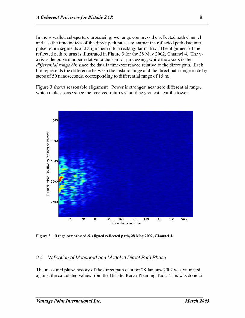
In the so-called subaperture processing, we range compress the reflected path channel and use the time indices of the direct path pulses to extract the reflected path data into pulse return segments and align them into a rectangular matrix. The alignment of the reflected path returns is illustrated in Figure 3 for the 28 May 2002, Channel 4. The y-axis is the pulse number relative to the start of processing, while the x-axis is the differential range bin since the data is time-referenced relative to the direct path. Each bin represents the difference between the bistatic range and the direct path range in delay steps of 50 nanoseconds, corresponding to differential range of 15 m. Figure 3 shows reasonable alignment. Power is strongest near zero differential range, which makes sense since the received returns should be greatest near the tower.
Figure 3 – Range compressed & aligned reflected path, 28 May 2002, Channel 4.
2.4 Validation of Measured and Modeled Direct Path Phase The measured phase history of the direct path data for 28 January 2002 was validated against the calculated values from the Bistatic Radar Planning Tool. This was done to
A Coherent Processor for Bistatic SAR 9
Vantage Point International Inc. March 2003
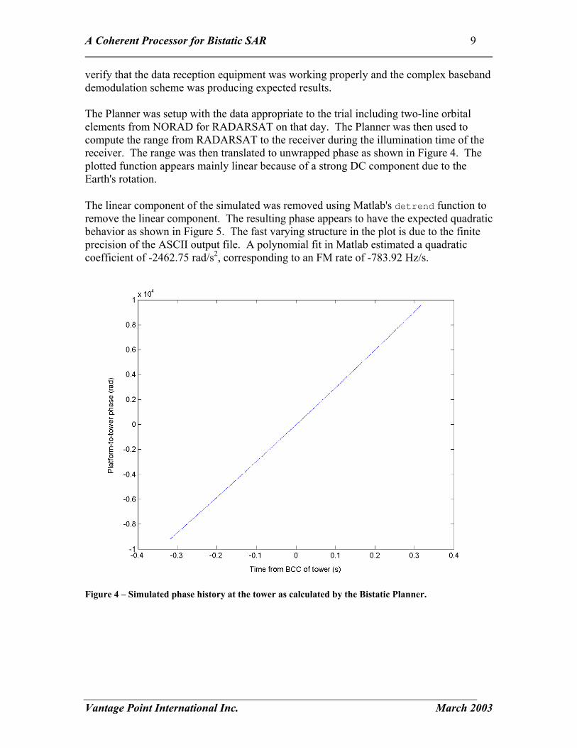
verify that the data reception equipment was working properly and the complex baseband demodulation scheme was producing expected results. The Planner was setup with the data appropriate to the trial including two-line orbital elements from NORAD for RADARSAT on that day. The Planner was then used to compute the range from RADARSAT to the receiver during the illumination time of the receiver. The range was then translated to unwrapped phase as shown in Figure 4. The plotted function appears mainly linear because of a strong DC component due to the Earth's rotation. The linear component of the simulated was removed using Matlab's detrend function to remove the linear component. The resulting phase appears to have the expected quadratic behavior as shown in Figure 5. The fast varying structure in the plot is due to the finite precision of the ASCII output file. A polynomial fit in Matlab estimated a quadratic coefficient of -2462.75 rad/s2, corresponding to an FM rate of -783.92 Hz/s.
Figure 4 – Simulated phase history at the tower as calculated by the Bistatic Planner.

A Coherent Processor for Bistatic SAR 10
Vantage Point International Inc. March 2003
Figure 5 – Simulated phase history at the receiving tower – linear phase removed.
The measured phase of the direct path channel data from the actual experimental data was extracted by baseband complex demodulating the data and range compressing it in Matlab. The phase was computed at the peak of each direct return pulse and plotted as a function of time in Figure 6. Note that Figure 6 is concave down, whereas Figure 5 is concave up. This is due to a conjugation that is implicit in the demodulation step, and which is taken into account when performing azimuth focusing. The phase can only be measured modulo 2π, and there is expected to be a linear phase change over time that is not known a priori. The linear phase offset is due to unavoidable slight mismatch in the local oscillator of the receiver and the local oscillator of RADARSAT, as well as unknown squint variations and/or uncertainty in the beam center crossing time estimation. The Matlab polynomial fit indicates a quadratic coefficient of -2477.89 rad/s2, corresponding to an FM rate of -788.74 Hz/s. Thus, the FM rate for the experimental and simulated data differ by less than 1%. In order to azimuth compress the data at each of the chosen ground cells, the processor reconstructs the phase history of the target from input XYZ data for the platform, target and receiver locations. This operation was validated by comparing the phase at the tower calculated by the Bistatic SAR processor to the one generated by the bistatic planner.

A Coherent Processor for Bistatic SAR 11
Vantage Point International Inc. March 2003
Figure 6 – Measured direct path phase history, 28 January 2002.
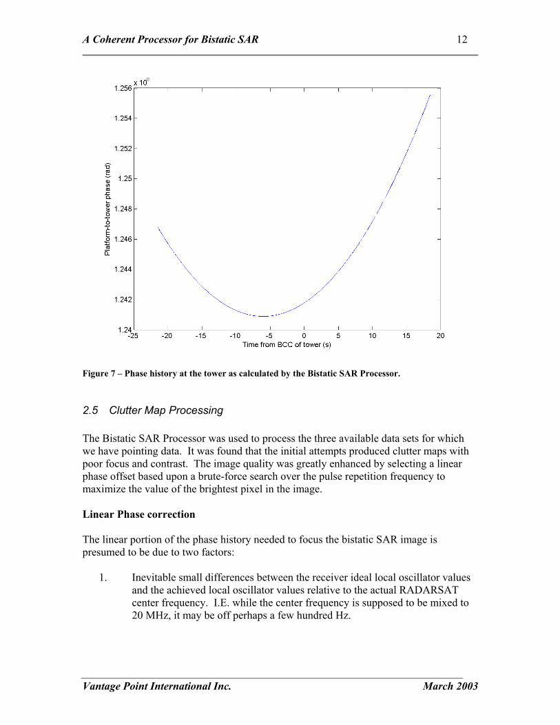
Figure 7 shows the phase function as calculated by the bistatic processor. A polynomial fit was done in Matlab to find a quadratic coefficient of -2452.74 rad/s2, corresponding to an FM rate of -780.73 Hz/s. The slight difference between the calculation of the planner (see above) is four tenths of one percent, and is believed to be due to the different interval in time over which the fit was made. The one done for the processor phase was done using the entire flight path (40 seconds).
A Coherent Processor for Bistatic SAR 12
Vantage Point International Inc. March 2003
Figure 7 – Phase history at the tower as calculated by the Bistatic SAR Processor.
2.5 Clutter Map Processing The Bistatic SAR Processor was used to process the three available data sets for which we have pointing data. It was found that the initial attempts produced clutter maps with poor focus and contrast. The image quality was greatly enhanced by selecting a linear phase offset based upon a brute-force search over the pulse repetition frequency to maximize the value of the brightest pixel in the image. Linear Phase correction The linear portion of the phase history needed to focus the bistatic SAR image is presumed to be due to two factors:
1. Inevitable small differences between the receiver ideal local oscillator values and the achieved local oscillator values relative to the actual RADARSAT center frequency. I.E. while the center frequency is supposed to be mixed to 20 MHz, it may be off perhaps a few hundred Hz.
A Coherent Processor for Bistatic SAR 13
Vantage Point International Inc. March 2003
2. The RADARSAT antenna beam may be slightly squinted. This creates a need to estimate the induced Doppler, which is analogous to Doppler centroid estimation in monostatic SAR.
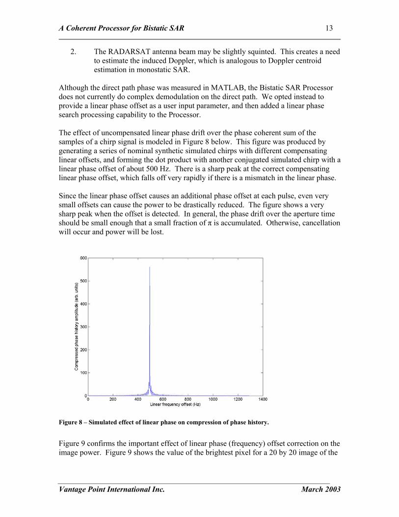
Although the direct path phase was measured in MATLAB, the Bistatic SAR Processor does not currently do complex demodulation on the direct path. We opted instead to provide a linear phase offset as a user input parameter, and then added a linear phase search processing capability to the Processor. The effect of uncompensated linear phase drift over the phase coherent sum of the samples of a chirp signal is modeled in Figure 8 below. This figure was produced by generating a series of nominal synthetic simulated chirps with different compensating linear offsets, and forming the dot product with another conjugated simulated chirp with a linear phase offset of about 500 Hz. There is a sharp peak at the correct compensating linear phase offset, which falls off very rapidly if there is a mismatch in the linear phase. Since the linear phase offset causes an additional phase offset at each pulse, even very small offsets can cause the power to be drastically reduced. The figure shows a very sharp peak when the offset is detected. In general, the phase drift over the aperture time should be small enough that a small fraction of π is accumulated. Otherwise, cancellation will occur and power will be lost.
Figure 8 – Simulated effect of linear phase on compression of phase history.
Figure 9 confirms the important effect of linear phase (frequency) offset correction on the image power. Figure 9 shows the value of the brightest pixel for a 20 by 20 image of the

A Coherent Processor for Bistatic SAR 14
Vantage Point International Inc. March 2003
28 January 2002 data. The peak is reported by the linear phase search and can then be entered by the user.
Figure 9 – Observed effect of linear phase offset on maximum image intensity.
Clutter Maps A 320x320 pixels clutter map was generated for all 4 available channel at all three trials of 28 January, 16 May and 28 May 2002. Figure 10 shows the clutter map image achieved for the 28 January 2002, channel 1 (full aperture) data. The aperture time was 0.3 seconds and the frequency offset was 494 Hz. This clutter image is used for the purpose of discussion and all other results are shown in appendix A. All maps were generated using the same ground point coordinates based on a 20 by 20 grid, interpolated by a factor of 16 using the Bistatic Processor’s interpolation feature to give 320 by 320 pixels. These output pixels have 20 m spacing over a region of roughly 6km square.

A Coherent Processor for Bistatic SAR 15
Vantage Point International Inc. March 2003
Figure 10 – Clutter map generated from full aperture data, 28 January 2002.
The range clutter map show good overall resolution with distinct features in different regions. Most of the resolution features observed are in agreement with the contours generated by the bistatic planner (section 2.2). In the receiving antenna viewing wedge, the resolution of high scatterers is very poor because of the range and Doppler gradients being parallel in this region. Thus several neighboring bins may have undistinguishable range and Doppler resulting in scatterers spread along the ellipses of constant bistatic range. It is also observed that the range resolution is much better in the region located east of the tower, than west of the tower. Scatterers on the right are clear points while those on the left appear stretched in range. This is due to the more closely spaced bistatic range contours in the east direction as illustrated in figure 1. The returned power is clearly larger in the region closest to the tower as expected. However, we do not observe a significant increase in amplitude inside the viewing wedge. This might be due to a bad evaluation of the limits of the antenna beam or to the fact the power of high scatterers is being spread over multiple cells in this region. A linear phase of 494 Hz was used based on the linear phase search results shown in Figure 9. This particular value maximizes the power of the brightest pixel in the compressed image. As indicated by Figure 9, other nearby linear phases achieve

A Coherent Processor for Bistatic SAR 16
Vantage Point International Inc. March 2003
reasonable compression although it was observed that changing the linear term also shifts the image in the azimuth direction. In the light of the present results, we recommend that further trials be done with the receiving antenna aiming at regions where better resolution is expected i.e. in the direction where the bistatic range contours are most closely spaced. In this direction, we expect a resolution of about half of that achieved with the monostatic equivalent.
2.6 Structure of Results CD-ROM The accompanying CD-ROM contains the clutter map results for the three sets of available data, specifically 28 January 2002, 16 May 2002, and 28 May 2002. There are four clutter maps for each date, one from the three recorded physical sub-apertures and one from the full aperture. In addition, the CD-ROM includes intermediate results and input files sufficient to allow regeneration of clutter maps. The data is organized in a directory structure as shown in Figure 11.
Figure 11 – Directory structure for results on CD-ROM.
The Jan28_2002 directory is representative of the other dates and the contents are as follows: Directory of . . . \Jan28_2002 03/29/2003 10:40p <DIR> . 03/29/2003 10:40p <DIR> .. 03/29/2003 08:39p <DIR> ch1 03/29/2003 09:29p <DIR> ch3 03/29/2003 10:08p <DIR> ch4
├───Jan28_2002 │ ├───ch1 │ ├───ch3 │ ├───ch4 │ └───ch5 ├───May16_2002 │ ├───ch1 │ ├───ch3 │ ├───ch4 │ └───ch5 └───May28_2002 ├───ch1 ├───ch3 ├───ch4 └───ch5

A Coherent Processor for Bistatic SAR 17
Vantage Point International Inc. March 2003
03/29/2003 07:43p <DIR> ch5 03/29/2003 02:19p 12,485 j28_ap0_1290hz.png 03/28/2003 01:28p 255,863 j28_location.jpg 03/28/2003 01:27p 21,200 j28_ptsXYZ.dat 03/29/2003 03:52p 271,317 j28_reg.dat 03/29/2003 03:59p 9,617 j28_reg.png 03/29/2003 05:56p 1,200 readme.txt 03/29/2003 10:40p 0 results.txt 7 File(s) 571,682 bytes 6 Dir(s) 120,055,140,352 bytes free The ch1 subdirectory of the Jan28_2002 directory is representative of the other channels and the contents are as follows: Directory of . . .\Jan28_2002\ch1 03/29/2003 10:43p <DIR> . 03/29/2003 10:43p <DIR> .. 03/29/2003 07:52p 57,460,440 ch1.dat 01/23/2003 04:04p 53 j28_baseXYZ.dat 01/31/2003 02:18p 2,550,000 j28_fpxyz.dat 03/29/2003 08:39p 103,478 j28_grnd.bmp 03/29/2003 08:39p 6,530,203 j28_grnd.dat 03/28/2003 01:27p 21,200 j28_ptsXYZ.dat 03/29/2003 07:40p 86,031 j28_reg.dat 7 File(s) 66,751,405 bytes 2 Dir(s) 120,055,144,448 bytes free The following table describes the content of input, intermediate and output files, based on the data from channel one of January 28th data. File Name Description Source ch1.dat Reflected path data, pulse compressed
and aligned SubAperture Channel Processing step
j28_baseXYZ.dat Location of the receive antenna Text input file j28_fpxyz.dat Flight path trajectory over time Text input file j28_grnd.bmp Output clutter map in .bmp format Ground Return Processing Step j28_grnd.dat Output clutter map in ASCII format Ground Return Processing Step j28_ptsXYZ.dat Ground points locations Text input file j28_reg.dat Pulse index file Direct Channel Processing Step

A Coherent Processor for Bistatic SAR 18
Vantage Point International Inc. March 2003
3 User’s Guide
3.1 Installation The Bistatic Processor is a stand alone application, which requires no specific DLLs other than those available with the Windows 2000 Operating System. In principle, you need only to copy the executable, Bistatic.exe, into a convenient directory on your file system and run the program. The CD-ROM contains a zip file which can be used to restore a directory structure which includes the executable, source code, and test data that can be used to generate the clutter maps in this report. In order to regenerate all results from the very first steps, the raw radar signal data is needed, which is too large to be included on the CD-ROM. If the user is willing to re-use intermediate results, new clutter maps can be generated with different pixel spacing, aperture time, or ground coverage by providing appropriate user input and input data files. Information on how to build the application from the source code is provided in section 4.2 of this report.
3.2 Overview of Bistatic Processing Steps There are five main steps in processing of raw bistatic radar data to a clutter map:
1. Obtain the required two raw radar data files (direct and a reflected path file) and obtain or generate the three text input files that respectively describe the geometry of the tower, ground points to be imaged, and the platform as it travels through space.
2. Start the Bistatic SAR Processor application and load/specify the data files and optionally modify the processing parameters.
3. Process the direct path data to pulse compress and detect incoming pulses, measure their peak amplitude, and index their position in the file. Optionally save the direct channel registration results.
4. Process the reflected path data to pulse compress the data and parse it into pulses echo segments aligned with the direct path pulse arrival. Optionally save the reflected path pulse results.
5. Process the ground return to perform Doppler focusing on the reflected path results and produce the bistatic clutter map in ground coordinates. Optionally save the clutter map as a complex data file or a detected Windows bitmap file.
The Bistatic Processor allows the user to individually control the steps of processing, and allows the user to save and reload intermediate or final results. This has the advantage of

A Coherent Processor for Bistatic SAR 19
Vantage Point International Inc. March 2003
saving time during multiple runs, and also allows the intermediate processing to be verified and accessed for analysis.
3.3 The Five Required Input Files The program requires five specific files in order to generate a clutter map for the specified ground area. The files can be divided into two categories: the raw radar data files, which are large files of 8-bit binary data, and the bistatic scenario files, which are ASCII text files.
3.3.1 Raw Radar Data Files (Direct and Reflected Path) The bistatic processor requires two radar data files for processing. One data file is from the direct channel1, while the other should be from one of the reflected path channels2. The direct channel will be range compressed to find the arrival times of the pulses at the tower. The reflected path data will also be range compressed and parsed into a set of individual pulses using the times obtained from the direct path pulse detection. This operation results in range aligned data that is ready for azimuth compression. Each data file consists of a continuous time recording of one byte samples for the entire recording interval. It is assumed that the direct path and reflected path data are sampled synchronously in time according to a very stable clock. In the case where preprocessed direct and reflected path data is available (see how to generate preprocessed data in the next section), the user only needs to load in the preprocessed data in place of the raw data, and skip the range compression and registration steps (listed in section 3.4).
3.3.2 Satellite Flight Path File The Satellite flight path is expected to be a text file consisting of four columns of numbers. The first column is the time in seconds, from the start of the file, of the position of the platform recorded in the next three columns in any right-handed Earth-centered, rotating Cartesian coordinate system. The position in the next three columns is the X, Y, Z values in meters. An excerpt from a valid flight path file follows: 0.00000000 578681.01786432 -5395613.75716064 4685538.31873230 0.00100000 578678.65657026 -5395609.20781461 4685543.84855899
1 For the data of 28 January, 16 May and 28 May 2003, the direct path was always in channel 2. 2 For the data of 28 January, 16 May and 28 May 2003, the reflected path data was one of channels
1, 3, 4 or 5.

A Coherent Processor for Bistatic SAR 20
Vantage Point International Inc. March 2003
0.00200000 578676.29527624 -5395604.65846243 4685549.37838063 0.00300000 578673.93398227 -5395600.10910412 4685554.90819719 0.00400000 578671.57268833 -5395595.55973965 4685560.43800871 0.00500000 578669.21139444 -5395591.01036904 4685565.96781515 0.00600000 578666.85010058 -5395586.46099229 4685571.49761654 0.00700000 578664.48880676 -5395581.91160939 4685577.02741285 The flight path must be carefully selected to ensure that all imaged ground points and receiving tower are illuminated at some time during the flight described by the satellite flight path. Failure to respect this condition can prevent the SAR processor from running properly.
3.3.3 Ground Points File The ground points are expected in a text file consisting of three columns of numbers. Each row of three numbers is the X, Y, Z coordinate in meters of one ground point, in an Earth-centered, rotating Cartesian coordinate system identical to that used for the satellite flight path. These ground points will be used to generate the clutter map for the area specified in the file. The following is a sample of the ground point file: 1168303.57087537 -4509964.96538425 4341745.07359766 1168276.68284225 -4509861.17036866 4341865.37159259 1168249.41445868 -4509755.90709837 4341984.24677009 1168221.05909595 -4509646.44779715 4342099.05478283 1168193.31579654 -4509539.35122442 4342216.15297485 1168165.47892046 -4509431.89342064 4342332.90099564 1168137.28283080 -4509323.04895615 4342448.30465529 1168108.93233195 -4509213.60843079 4342563.13026173 1168080.94609307 -4509105.57404660 4342679.31902559 In order for the output image and saved bitmap clutter maps to make sense, it is recommended that the ground points be from a rectangular grid of points on the ground, listed from the top right corner, running down column-wise from right to left. This is the way the clutter map pixels will be rendered on the display window and Windows bitmap (.bmp) file. For a “North-Up” configuration normally this will mean that the ground points start from the North-West corner, running south along columns, then working from East to West. Any consistent definition will work, however, and the user may note that any projection can be handled by the ground points file.
3.3.4 Tower Location File The tower location is expected to be in a text file consisting of three numbers. The numbers represents the X, Y and Z coordinates of the antenna atop the receiving tower, in

A Coherent Processor for Bistatic SAR 21
Vantage Point International Inc. March 2003
meters. The coordinate system must be the same Earth-centered rotating coordinate system used for the flight path and ground points files. The following is a sample of the tower location file content: 1172577.00509323 -4504900.63558226 4345837.55764660 These numbers correspond to the antenna location reported by AFRL to be at the following location: 43 deg 13 min 29.092 sec N 75 deg 24 min 36.947 sec W Elev 525.8 ft MSL (53.3 ft AGL) Note that the precision is to the nearest thousandth of a degree, which would correspond to 3 cm accuracy at the equator, and better than that at higher latitudes.
3.4 Specifying Files and Processing Parameters in the Bistatic Processor The Bistatic Processor can be started by double clicking on the Bistatic.exe executable or by any other standard Windows method. The loading of files is done using the File drop down menu, while processing parameters are set under the Process drop down menu. Raw Bistatic Radar Files To specify the name of the Direct Channel Data: 1. Select the menu item File->Open Direct Channel 2. Using the file dialog, specify the file containing the direct channel data. To specify the name of the Reflected Channel Data: 1. Select the menu item File->Open SubAperture Channel 2. Using the file dialog, specify the file containing the reflected channel data. Note: If you are only Processing the direct path, you only need to specify the direct path data file. Similarly if you have loaded Direct Path Results Satellite Flight Path File To load the satellite flight path data into the processor: 1. Select the menu item File->Open Platform Path 2. Using the file dialog, specify the file containing the ascii flight path data. Press the
OK button. 3. When the flight path data has been loaded a window will open listing all the flight
path entries in a table layout. Ground Points File To load the ground points coordinates into the processor:
A Coherent Processor for Bistatic SAR 22
Vantage Point International Inc. March 2003
1. Select the menu item File->Open Ground Point Data 2. Using the file dialog box specify the file with the text ground point data. Press the OK
button. 3. When the ground point data has been loaded a window will open listing all the
ground point entries in a table layout.
The processor includes a feature for interpolating ground points for creating a denser grid in order to get an image with finer pixel spacing. To interpolate ground points: 1. Make sure that the ground points table is the current focus window (i.e. the title bar is
highlighted by clicking on that window with the mouse). 2. Select the menu item Process->Interpolate Ground Points. 3. A dialog box will open for you to select the interpolation factor in powers of two
from 2 to 64. 4. Press the OK button. When the interpolation is complete the window with the ground
point data in tabular form will refresh. The program reports the pixel spacing to aid in data interpretation.
Note: If you change your mind about the interpolation factor, do not select interpolation a second time, or you will compound the interpolation (interpolate the already interpolated data). You may need to restart the processor, reload the ground points, and select the interpolation factor anew. On the other hand it can be very convenient to further interpolate in order to refine image detail by using the interpolation repetitively. Tower Location File To load the antenna tower coordinates into the processor: 1. Select the menu item File->Open Tower Location 2. Using the file dialog specify the file with the tower location. Press the OK button. 3. When the tower location has been loaded a window will open displaying the tower
location. Processing Parameters A dialog box is dedicated for optionally modifying the parameters used for range and azimuth compression calculations. Before performing any processing, make sure those parameters reflect the parameters of the data that is being processed. To specify the processing parameters: 1. Select the menu item Process->Processing Parameters 2. A processing parameter dialog box will open and allow you the specify some of the
processing parameters. The parameters include Pulse Width, Sampling Rate, Band width and nominal PRF. Enter the correct values for your scenario.
3. Press the OK button.
A Coherent Processor for Bistatic SAR 23
Vantage Point International Inc. March 2003
Note: The processing parameter values are not saved between sessions, but there are defaults. The defaults for the processing parameters are sufficient for the data used in this report and are as follows:
• Pulse width = 42 usec • Sampling rate = 80 MHz • Bandwith = 11.56 MHz • Nominal PRF = 1290 Hz
If the defaults are suitable, there is no need to set processing parameters.
3.5 Processing the Direct Path Data
This step is necessary to index the time of arrival of the direct data pulses. These times will be used to extract and align the reflected path pulses (see section 3.6). In order to do this the direct path pulses must be range compressed and their peaks detected and measured in terms of amplitude and time of arrival for each pulse. Section 4.3 describes the algorithms used. The result of direct path processing is a list of pulse indexes. To perform pulse indexing of the direct channel
1) Select the menu item Process->Process Direct Channel 2) A direct channel processing dialog will open. This will allow you to specify what
part of the data file to process. Enter the starting sample and the number of samples to process. Press OK to begin generating the direct channel registration. Note: It is assumed that 1 sample = 1 byte.
3) A dialog will open informing you of the number of pulses found and the Beam Center Crossing pulse for the Tower.
The resulting pulse arrival times may be saved as a text file for subsequent processing. To save the results of the direct channel indexing: 1. Select the menu item File->Save Direct Channel Processing 2. Using the file dialog specify the file to save the registration data in. Press the OK
button. The resulting file will consist of three columns of numbers. The first column is the sample location (in bytes) for a pulse peak. The second column is the difference between this sample location and the previous. The third column is the value of the peak found. A sample of the output follows: 530011093 0 9.58058e+007 530073139 62046 7.30718e+007 530135188 62049 7.4375e+007 530197236 62048 9.85295e+007 530259284 62048 1.17766e+008 530321332 62048 1.25308e+008 530383380 62048 1.21441e+008 530445428 62048 1.06424e+008
A Coherent Processor for Bistatic SAR 24
Vantage Point International Inc. March 2003
530507474 62046 8.43222e+007 530569523 62049 6.90474e+007 530631571 62048 9.63281e+007 If pre-processed data is available the entire indexing step may be skipped by loading the preprocessed results according to the following steps: 1. Select the menu item File->Load Direct Channel Registration. 2. Using the file dialog specify the file to read the registration data from. Press the OK
button. 3. A dialog box will appear to inform you that the direct channel registration has been
successfully loaded.
3.6 Processing the Reflected Path Data The pulse returns from the reflected path data chosen must be range compressed and then aligned (or registered) using the indexing information found during processing of the direct channel. This results in a set of complex valued range compressed pulses, aligned in a two-dimensional matrix to allow azimuth compression. The algorithms used for this are explained in section 4.3.2. To pre-process the reflected path data: 1. Select the menu item Process->Process Sub-Aperture 2. A dialog box will open asking for the number of registered pulses to extract from the
sub-aperture. Press the OK button to begin extracting pulses from the sub-aperture. The resulting range compressed data may be saved as a text file for subsequent processing. To save preprocessed reflected path data: 1. Select the menu item File->Save SubAperture Processing 2. Using the file dialog specify the file to save the registration data in. Press the OK
button. The output is a plain text file with the results of one pulse per line. Each line will have alternating real and imaginary values. An example of one line from the output follows: 3.02763 123.56 -34.8824 134.443 -66.7635 120.386 -80.1432 97.7644 -81.5716 80.7402 -81.4352 68.8874 -80.4801 55.6411 -72.8658 40.596 -56.2021 30.5235 -35.8419 32.3259 -22.0636 46.3523 -22.9989 63.8076 -36.719 71.2417 -50.3041 61.6307 -50.2387 41.6905 -34.3541 25.8997 -12.1267 23.6654 5.01982 33.7105 11.504 48.3262 8.61308 59.8093 1.73613 64.6608 -4.44836 64.7964 -10.116 63.7101 -17.7855 60.6069 -25.2526 51.9589 -26.3021 40.0127 -20.9628 33.4762 -18.6507 35.7221 -25.9188 38.2787 -36.3816 32.0278 -39.3147 20.2755 -34.4617 13.8196 -31.259 15.9284 -35.2699 19.1535 -41.8708 16.0684 -43.121 7.38775 -35.869 -0.697379 -22.6523 -2.78665 -8.51409 2.92417 1.59955 14.8283 4.20689 28.7827 -1.80233 38.8457 -13.7127 38.2264 -23.4106 22.5429 -19.9326 -4.54937 1.76126 -30.0647 33.8773 -40.5428 60.9723 -33.7641 73.2015 -19.4932 72.4672 -8.51233 66.0272 -3.78488 57.9949 -2.37011 48.2905 -1.77175 36.3148 -2.16904 23.0317 -5.0108 11.2759 -11.78 6.07613 -22.4024 12.832 -32.4434 31.9794 -33.1545 55.4671 -17.7088 71.2343 11.4656

A Coherent Processor for Bistatic SAR 25
Vantage Point International Inc. March 2003
When preprocessed data is already available, skip the entire range registration step by following these steps: 1. Select the menu item File->Load Sub-Aperture Results 2. Using the file dialog specify the file to read the sub-aperture results from. Press the
OK button 3. A dialog box will appear to inform you that the sub-aperture results have been
successfully loaded.
3.7 Processing the Ground Return to a Clutter Map At this stage the radar data can be processed to the ground points as described in section 2.5. The speed of this operation greatly depends on the size of the image and aperture time that will be used . To generate an image from the data that is currently in memory: 1. Select the menu item Process->Process Ground Return. 2. A dialog will open allowing you to specify the linear phase rate and the aperture time.
Press the OK button 3. When the processing is complete a window will open and display a gray scaled
version of the result. The next section describes how to save the resulting clutter map. The processor features a searching capability for finding the correct linear phase correction to be used for azimuth processing. This is a very time consuming step since the image is generated for each test phase rate. It is best to use a small image if you need to do a very broad search. The range of frequencies only has to be as wide as the PRF of the radar. To perform a linear phase correction search: 1. Select the menu item Process->Linear Phase Search 2. A dialog box will open allowing you to specify the start, stop a frequency step to
search with. Press the Ok button. 3. When the search is complete a dialog box will open and indicate the best linear phase
to use. Note: It is assumed that the best linear phase frequency offset is the one that maximizes the maximum pixel value in the resultant image. Saving Clutter Maps The resulting clutter map can be saved in two formats, a windows BMP file and a text file. The bistatic processor applies an automatic scaling of the results to fit a grayscale image. The image is displayed automatically upon completion of processing in a window, but will often be hard to read since it maps each pixel to a single screen pixel. It is best to save the BMP file and view it in a paint program which will have a zoom capability.

A Coherent Processor for Bistatic SAR 26
Vantage Point International Inc. March 2003
The plain text file consists of five columns of numbers. Each row consists of the three position values (X, Y, Z) in meters along the real and imaginary resulting values. This text file can be loaded back into the bistatic processor later. For saving a BMP image 1. Select the menu item File->Save Image 2. Using the file dialog specify the file to save the image as. Note that you need to
manually type in the .bmp file extension. Press the OK button. For saving a text file 1. Select the menu item File->Save the Ground Return Data 2. Using the file dialog specify the filename (including extension) to save the data in.
Press the OK button. Loading Clutter Maps The text ground return data saved in the previous section can be reloaded at a later time. 1. Select the menu item File-.Load Ground Return Data 2. Using the file dialog select the file containing the ground return data. Press the OK
button. 3. When the data has been loaded a window will open with a grayscale image of the
data.

A Coherent Processor for Bistatic SAR 27
Vantage Point International Inc. March 2003
4 Programmer’s Guide
4.1 Application Overview The Bistatic processor is an application that processes radar signal data generated from a bistatic configuration. The application is divided into three major components, a User Interface, Bistatic Processing library and a small Exception library. Each of the libraries are statically linked to the User Interface. This division of the application into three components was done to separate user interface from the core bistatic processing. This makes it easier to modify the either component without necessarily having to change the other. Some of the main algorithms used in the application and library will be described here. Some collaboration diagrams will be used to illustrate how the objects work together to process the radar data.
4.2 Building the Bistatic Processor from the Source Code Using MS Visual C++ 6.0, open the workspace file "BistaticGUI.dsw" located in the "BistaticProcessor/BistaticGUI" folder. The workspace consists of three MS Visual C++ projects (Bistatic, BistaticExceptions and BistaticGUI). Each of these projects are contained in their own subdirectroy. The Bistatic project, contained in the BistaticProcessor/Bistatic" folder, is a statically linked library. The bistatic library contains the main processing algorithms. The BistaticExceptions project, contained in the "BistaticProcessor/BistaticExceptions" folder, is also a statically linked library. The development of this library hasn't kept pace with the development of the Bistatic library or the BistaticGUI. It contains only a few classes that are are currently used in some parts of the Bistatic Processor. The BistaticGUI project, contained in the "BistaticProcessor/BistaticGUI" folder, is the main application for the Bistatic Processor. The BistaticGUI project contains all the user interface components. Each of the projects will be automatially opened into the MS Visual C++ development environment. Workspace Statistics Files Folders Size Bistatic Library: 47 3 139600 Bytes BistaticExceptions Library: 11 3 10514 Bytes BistaticGUI: 76 4 771590 Bytes Bistatic Processor(total): 134 13 921704 Bytes Before building the application ensure that the correct project is selected for building. From the main menu select "Build->Set Active Configuration...". A dialog box titled "Set

A Coherent Processor for Bistatic SAR 28
Vantage Point International Inc. March 2003
Active Project Configuration" will open. Select either "BistaticGUI - Win32 Release" or "BistaticGUI - Win32 Debug". The debug version runs slower but can be useful when developing. Press the OK button. The application can now be built by selecting from the main menu "Build->Build Bistatic.exe". Since the BistaticGUI project depends on the Bistatic and BistaticException projects, these projects will be built before the BistaticGUI is built. If the "BistaticGUI - Win32 Release" configuration was chosen the applicaiton (Bistatic.exe) will be in the "BistaticProcessor/BistaticGUI/release/" folder. If the "BistaticGUI - Win32 Debug" configuration was chosen, the application (Bistatic.exe) will be in the "BistaticProcessor/BistaticGUI/debug/" folder. The application can now be run.
4.3 Program Flow & Algorithm Description In the following subsections we distinguish the three main processing algorithms. First, the direct path processing handles all the steps from direct path data selection, to generation of pulses indices including range compression and pulse detection. The second subsection presents the reflected path data processing, including data selection, range compression and pulse registration. Finally, the clutter map processing is presented, with documented steps regarding computation of range walk, phase reconstruction and coherent summation from pulse to pulse.
4.3.1 Direct Path Processing Program Flow This process starts at: bool CBistaticGUIApp::rangeCompressAndRegister()
1) Request region of file to process through the CDirectChannelProcessingDialog dialog box. If user pressed the OK button the proceed to 2) otherwise exit.
2) Transfer the input from the dialog box to the CbistiaticProcessor 3) Start a thread to execute the registration function bool CBistaticProcessor::registerPulses(). This will call the function void CDirectChannel::rangeCompressAndRegister(CBistaticProcessor &processor) to do the work of finding the pulses. 4) Create a progress dialog box to show the user the status of the process. 5) Start a thread to update the progress dialog box with the status of the process. 6) Wait for either the user to cancel or the process to end.
Detail of the Range Compress and Register function void CDirectChannel::rangeCompressAndRegister(CBistaticProcessor &processor).

A Coherent Processor for Bistatic SAR 29
Vantage Point International Inc. March 2003
A complete listing of the function rangeCompressAndRegister can be found in Appendix D. Algorithm Summary Process data from the StartSample to the StartSample+NumberOfSamples
1) Read 4096 samples
2) Pad the data read with 4096 zeros
3) Call the void CAMTIProcessor::RangeCompress(complex<double> *data,
int dataSamples, vector<int> *PeakSamples,
vector<double> *PeakValues) function to process the data read. This function performs the following steps.
a) FFT the data b) Multiply the data by the matched filter c) Inverse FFT the data d) Search the data for a peak
A listing of the function RangeCompress can be found in Appendix E.
4) For all peaks found adjust the sample to reflect the sample relative to the start of the file.
5) If a peak was found jump to the location of the next peak. This jump is estimated based on the nominal PRF.
6) Else move back 4096 samples once then reprocess and move forward by 4096 samples each time to search for a peak.
End process when the requested NumberOfSamples has been passed Notes:
1. It is currently assumed that 1 sample = 1 byte. Improvements could be made to allow for different sample sizes.
2. The search for the peak is based on a simple threshold level. When the data is above the level a search is made for the maximum. When the signal is near Bcc it becomes so strong that most values may be above the threshold and give a false peak position. This could be improved by making the threshold adapt to the signal level.

A Coherent Processor for Bistatic SAR 30
Vantage Point International Inc. March 2003
4.3.2 Reflected Path (Sub-Aperture) Processing Program Flow This process starts at: void CBistaticGUIApp::OnProcessSubaperature() ()
1) Request the pulses to process through the CsubAperatureProcessingDialog dialog box. If user pressed the OK button the proceed to 2) otherwise exit.
2) Transfer the input from the dialog box to the CbistiaticProcessor 3) Start a thread to execute the pulse return extraction function bool CBistaticProcessor::extractSubAperaturePulses(). This function will call void CSubAperature::extractPulses(CBistaticProcessor &processor, const vector<int> &pulseStart, int firstPulse, int numberOfPulses) to do the work of extracting the pulse returns. 4) Create a progress dialog box to show the user the status of the process. 5) Start a thread to update the progress dialog box with the status of the process. 6) Wait for either the user to cancel or the process to end.
Detail of extraction function void CSubAperature::extractPulses(CBistaticProcessor &processor, const vector<int> &pulseStart, int firstPulse, int numberOfPulses). A complete listing of the code for the function extractPulses can be found in Appendix F. Algorithm Summary Process the requested NumberOfPulses from the StartPulse
1) Read 4096 samples from the (PulseStart – 2048 –100) The pulse start was determined while registering the direct channel. The factor 2048 is subtracted to compensate for the shift that occurs in the CAMTIProcessor::RangeCompress function used for processing. The 100 was applied to ensure that we get the beginning of the pulse, this is removed when the data is move to the CpulseReturn object.
2) Pad the data read with 4096 zeros 3) Range compress the data using CAMTIProcessor::RangeCompress 4) Quadrature demodulate the data and decimate by 4. by calling
int CBistaticProcessor::qdemod1(const complex<double> *in, complex<double> *out, int samples, int decimate)

A Coherent Processor for Bistatic SAR 31
Vantage Point International Inc. March 2003
This function was adapted from a MATLAB function. It convolves the input data with two filters designed to extract the real and imaginary values from the signal. The filter coefficients are shown in Figure 12 - In-phase and Quadrature filters. The demodulated data is then decimated as it is copied to the output vector.
Figure 12 - In-phase and Quadrature filters
5) The quadrature demodulated data is then copied to CpulseReturn object and
stored in a vector. 6) Repeat until all the requested pulses have been extracted.
End Pulse extraction

A Coherent Processor for Bistatic SAR 32
Vantage Point International Inc. March 2003
4.3.3 Ground Return (Clutter Map) Processing Program Flow This process starts at:
void CBistaticGUIApp::OnProcessGroundImage() 1) Request the linear phase adjustment and the aperture time for processing through
the CgroundImageProcessingDialog dialog box. If user pressed the OK button the proceed to 2) otherwise exit.
2) Transfer the input from the dialog box to the CbistiaticProcessor 3) Start a thread to process the radar signal to a ground image. The thread will call bool CBistaticProcessor::computeGroundReturn(). This function will do the work of processing the radar return to the ground points. 4) Create a progress dialog box to show the user the status of the process. 5) Start a thread to update the progress dialog box with the status of the process. 6) Wait for either the user to cancel or the process to end.
Detail of processing for the ground point. bool CBistaticProcessor::computeGroundReturn(CBistaticScenario &scenario) A listing of the function computeGroundReturn can be found in Appendix G. Algorithm Summary For each ground Point
1) Determine the pulses of interest based on the Bcc time of this point and the aperture time specified by the user
2) For each of the pulses of interest i. Get the difference between the bistatic range for this point at this pulse
time and the direct range to the tower. Use this difference in range to determine which bin is of interest.
ii. Get the Bistatic Range for this point at this pulse time compute the number of wavelengths in the bistatic range. A wavelength of 0.0566m is used. Compute the fractional part of the wavelength.
iii. Compute the linear phase offset and the fraction of a cycle. iv. Add the linear phase cycle fraction and the wavelength fraction.
Compute the resulting fraction of a cycle. v. Convert this fraction of a cycle to an index in the phase lookup table.
There are 4000 entries in the look up table for the complex phase values. This should provide enough accuracy. A look up table was used to avoid the computing sines and cosines, as they require a lot of computational power.
vi. Multiply the return from the bin determined in i with the linear phase and add it to a running total.

A Coherent Processor for Bistatic SAR 33
Vantage Point International Inc. March 2003
3) End Pulse Loop
4) Set the return value for the ground point to the total return value. End Ground Point Loop
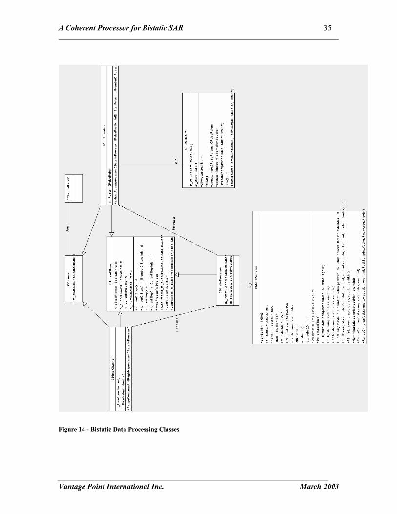
4.4 Bistatic Library In this section the contents of the bistatic library will be described. A complete description of all the classes will make it easier to understand, use and update this library. The Bistatic library is divided into two main classes. First, the classes encapsulating the bistatic scenario of the satellite, tower and ground points. Second, the classes encapsulating the data and the processing functions. The Bistatic Scenario consists of: CPlatformPath: Holds the satellite positions CFixedReceiver: Holds the position of the tower CgroundPoints: Holds the specified ground points of interest. All of the above classed are attributes of the CBistaticScenario class. The position values are encapsulated in four point classes (Cpoint1D, Cpoint2D, Cpoint3D, Cpoint4D). This structure is encapsulated in Figure 13 - Bistatic Scenario Classes. The data and processing functions consist of a set of classes to handle the channel data and a processor class. A brief description of the main classes is given below and the relationship of the classes is illustrated in Figure 14 - Bistatic Data Processing Classes CChannelDataIO: Provides a buffered file reading capability for the Cchannel clasess
CChannel; Base class for the direct channel and the sub-aperture. Provides an interface with the CchannelDataIO class
CDirectChannel: Inherits from Cchannel and provides specific processing necessary for the direct channel.
CsubAperature: Inherits from Cchannel and provides specific processing necessary for the subaperture.
CAMTIProcessor: Encapsulates the signal processing functions supplied by Jake Tunaley CBistaticProcessor: Inherits from the CAMTIProcessor. Adds more processing and has
the direct channel and sub-aperture as attributes.

A Coherent Processor for Bistatic SAR 34
Vantage Point International Inc. March 2003
Figure 13 - Bistatic Scenario Classes
A Coherent Processor for Bistatic SAR 35
Vantage Point International Inc. March 2003
Figure 14 - Bistatic Data Processing Classes

A Coherent Processor for Bistatic SAR 36
Vantage Point International Inc. March 2003
Thread functions were also developed to execute some of the more time consuming steps in processing the bistatic radar data. This was necessary because otherwise the User Interface becomes unresponsive while these steps are done. The Windows operating system requires application to check the message queue periodically. If the message queue is not checked Windows may try to shut down the application as a process that is not responding. Also, it is not possible to terminate a process once it has started without threading. These are the functions used in threading the application UINT BeginComputeGroundReturnThread(LPVOID pParam) This thread executes the function to process the radar returns for each ground point. UINT BeginExtractThread(LPVOID pParam) This thread executes the function to extract the radar returns from the sub-aperture based on the direct channel registration. UINT BeginLoadThread(LPVOID pParam) This thread loads the satellite flight path data. This can be quite a long set of data points and can take some time to load. UINT BeginRangeCompressThread(LPVOID pParam) This thread executes the function to range compress the direct channel and find the pulses.
4.5 User Interface The user interface is based on the “Muliple Document Interface” application design available in MS Visual C++. This application design uses the “Document-View” architecture as a basis for the project. During the development of this application this architecture was not strictly adhered to. Much of the interaction occurs through the main application class CBistaticGUIApp.

A Coherent Processor for Bistatic SAR 37
Vantage Point International Inc. March 2003
5 Discussion, Conclusions and Recommendations
5.1 Discussion The results show that the data contain useful bistatic information that can be processed to produce clutter maps that seem to agree with expectations in many aspects. Specifically we see evidence of resolution similar to that expected, some structure along bistatic range contours, and occasional bright returns. That being said, the image quality falls short of that expected for mono-static SAR images. There are several explanations that are most likely all true to some extent:
1. The experimental geometry chosen limits the image quality because the contours of constant bistatic range and the contours of bistatic Doppler are nearly parallel. This leads to streaks in the image which correspond to elongated ground patches which are collapsed into single resolution cells in bistatic range/Doppler space.
2. The experimental geometry limits resolution in the bistatic range direction because the receive antenna is pointed towards the illuminator instead of away from the illuminator, leading to reduced resolution across bistatic range. Judging from the contour spacing, resolution is 3-4 times coarser than it would be for a better antenna pointing geometry, and features in the clutter map seem to confirm this.
3. The Bistatic SAR Processor is a completely new development and the algorithms and code incorporated into it are mostly first generation. Notably the methods for detecting the tower BCC, estimating ground point BCC, and dealing with missing pulses need to be refined.
The amplitude of the direct path seems to take a distinct dip in the middle of the beam. Since the current method of detecting BCC searches for the maximum, the BCC is not precisely aligned which would misplace the aperture time by as much as one or two tenths of a second. Note that this will not affect the phase history overly since we have used a linear search for the best linear phase frequency offset which should compensate for small time offsets. Throughout the final phase of the project, minor errors or improvements were discovered which greatly improved the clutter map image quality. While we have produced some credible clutter maps it is possible and even probable that image quality might be further improved with on-going effort. The current method for detecting the tower beam center crossing time (BCC) uses a simple maximum peak power to fix the BCC pulse position in the data. Examination of the peak power plots shows that the data are somewhat noisy and bi-modal. This can lead to placement of the BCC several tenths of a second away from the centroid of the beam.

A Coherent Processor for Bistatic SAR 38
Vantage Point International Inc. March 2003
The method for estimating the BCC time for ground points is not particularly general and should be revisited so that it can work reliably at all latitudes. An experimentally derived squint angle relative to the zero Doppler is currently used. In the May data sets there are cases where the direct path becomes sufficiently weak that the direct pulses are lost either due to antenna nulls or other phenonema. The current method for handling drop outs is to ignore the pulse, which will introduce small errors in the time continuity which might limit image quality.
5.2 Conclusions Based upon this work we are able to offer the following conclusions:
1. We have developed a bistatic SAR processor capable of producing a clutter map from a set of bistatic radar data (direct path and reflected path signals) and the imaging geometry.
2. The processing of a bistatic SAR image consist of three main procesing steps: indexing of range compressed direct path data, registration of range compressed reflected path data and azimuth compression base on the phase history.
3. The resolution of the resulting clutter maps depends greatly on the linear frequency offset used in the coherent summation of azimuth contribution for each cell. That linear frequency is believed to be due to RADARSAT’s squint and mismatch between RADARSAT and receiver local oscillators.
4. The generated clutter maps are in general agreement with the investigation of the imaging scenarios done using the Bistatic planning tool.
5.3 Limitations and Recommendations for Future Work Resources are finite and some requirements were recognized only once the data processing was already well-advanced. As a result, there are several areas where the Bistatic Processor could be improved:
1. The method for detecting the beam center crossing time (BCC) in the pulse compressed data should be made more robust.
2. The method for estimating the BCC time for each ground point should be made more robust so that it will work at any latitude.
3. The processing speed should be enhanced. 4. A log file should be generated automatically to capture results currently
reported only in dialogue boxes and to improve documentation and repeatability of processing runs.
5. The provisions for handling missing data should be enhanced to eliminate time distortions caused by occasional skipped pulses.

A Coherent Processor for Bistatic SAR 39
Vantage Point International Inc. March 2003
6. Dialogue boxes should be reviewed and modified to make them more accurate, consistent and informative. For instance “SubAperture Processing” is more properly “Reflected Path Processing”, and some results dialogue boxes and windows do not identify the input data corresponding to the results.
We also offer for consideration three further recommendations related to data analysis and planning of trials:
7. Future experiments of this type should be planned so that the receive antenna is pointed in a direction where the bistatic range and Doppler contours are orthogonal. In particular receive antenna pointing should be toward ground patches where bistatic range contours are dense and orthogonal to bistatic Doppler contours. This should yield better results with roughly rectangular resolution cells and improved resolution.
8. The remaining data sets in table one should be characterized in terms of the antenna pointing used, in order to attempt to select a trial where the conditions of recommendation 7 are approximated.
9. Regardless of the outcome of recommendation 8, all other trials dates should be processed since they may provide further insight. This is especially likely since we have seen that features well outside of the assumed viewing angle of the receive antenna are visible to some degree.
6 References 1. Tunaley, James., RADARSAT Bistatic Experiment: Description and Analysis, DRDC-O,
Ottawa, 2002. 2. St.-Hilaire, M., Saper, R., and Seymour, M., Bistatic Radar Planning Tool Documentation,
Vantage Point International Inc., June 2001. 3. Inkol, R.J. & R.H. Saper, Digital Quadrature Demodulation for Radar ESM Applications,
DREO Technical Note 92-10, May 1992. 4. Curlander, John C., and McDonough, Anthony P., Synthetic Aperture Radar Systems and
Signal Processing, John Wiley & Sons, Inc., New York, 1991.

A Coherent Processor for Bistatic SAR 40
Vantage Point International Inc. March 2003
Appendix A: Experimental Results for 28 January 2003 January 28, 2002 ************************************* Direct Channel Registration Input Start Sample: 0 Number Of Samples: 640,000,000 Result Total Pulses: 9333 Bcc Sample: 618801475 Bcc Pulse: 8991 Nominal PRF: 1289.345Hz Registration saved in: J28_reg.dat ************************************* Aperture Pulse Extraction Register direct channel for the region of interest Input Start Sample: 460,000,000 Number Of Samples: 180,000,000 Result Total Pulses: 2884 Bcc Sample: 618863543 Bcc Pulse: 2543 Nominal PRF: 1289.32Hz Registration saved in: ch1/J28_reg.dat Registration saved in: ch3/J28_reg.dat Registration saved in: ch4/J28_reg.dat Registration saved in: ch5/J28_reg.dat ** Channel 1 Input Start Pulse: 0 Pulses To PRocess: 2884 Result saved int ch1/ch1.dat

A Coherent Processor for Bistatic SAR 41
Vantage Point International Inc. March 2003
** Channel 3 Input Start Pulse: 0 Pulses To PRocess: 2884 Result saved int ch3/ch3.dat ** Channel 4 Input Start Pulse: 0 Pulses To PRocess: 2884 Result saved int ch4/ch4.dat ** Channel 5 Input Start Pulse: 0 Pulses To PRocess: 2884 Result saved int ch5/ch5.dat ********************************* Linear Phase Search Input Start Frequency: 0 Stop Frequency: 1290 Frequency Step: 2 Output Best Frequency 494Hz Saved in: j28_ap0_1290hz.png ********************************* Interpolate Ground Points Initial Pixel Spacing: 325m Select: x 16 Resulting Pixel Spacing: 20.3m ******************************
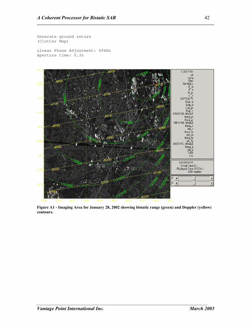
A Coherent Processor for Bistatic SAR 42
Vantage Point International Inc. March 2003
Generate ground return (Clutter Map) Linear Phase Adjustment: 494Hz Aperture time: 0.3s
Figure A1 - Imaging Area for January 28, 2002 showing bistatic range (green) and Doppler (yellow) contours.

A Coherent Processor for Bistatic SAR 43
Vantage Point International Inc. March 2003
Figure A2 - January 28, 2002 Direct Path Power
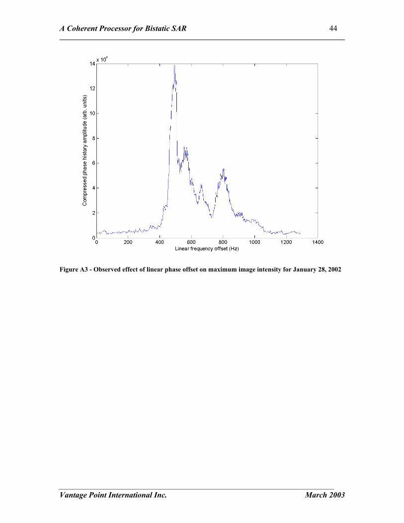
A Coherent Processor for Bistatic SAR 44
Vantage Point International Inc. March 2003
Figure A3 - Observed effect of linear phase offset on maximum image intensity for January 28, 2002
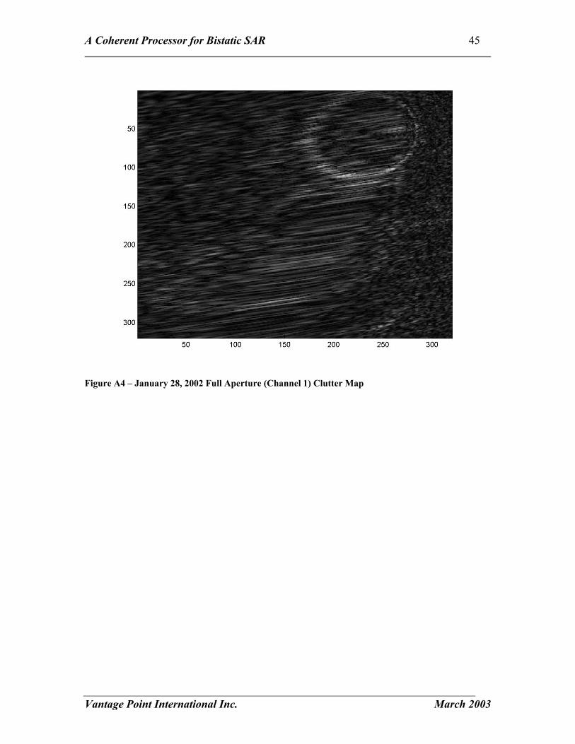
A Coherent Processor for Bistatic SAR 45
Vantage Point International Inc. March 2003
Figure A4 – January 28, 2002 Full Aperture (Channel 1) Clutter Map

A Coherent Processor for Bistatic SAR 46
Vantage Point International Inc. March 2003
Figure A5 - January 28, 2002 Sub-Aperture channel 3 clutter map

A Coherent Processor for Bistatic SAR 47
Vantage Point International Inc. March 2003
Figure A6 - January 28, 2002 Sub-Aperture channel 4 clutter map

A Coherent Processor for Bistatic SAR 48
Vantage Point International Inc. March 2003
Figure A7 - January 28, 2002 Sub-Aperture channel 5 clutter map

A Coherent Processor for Bistatic SAR 49
Vantage Point International Inc. March 2003
Figure A8 - January 28, 2002 Sum of Sub-Aperture channels 3, 4 & 5

A Coherent Processor for Bistatic SAR 50
Vantage Point International Inc. March 2003
Appendix B: Experimental Results for 16 May 2003 May 16, 2002 ************************************* Direct Channel Registration Input Start Sample: 0 Number Of Samples: 1811939328 Result Total Pulses: 16154 Bcc Sample: 1007287554 Bcc Pulse: 6695 Nominal PRF: 1287.7885Hz Registration saved in: m16_reg.dat ************************************* Aperture Pulse Extraction Register direct channel for the region of interest Input Start Sample: 970,000,000 Number Of Samples: 180,000,000 Result Total Pulses: 2213 Bcc Sample: 1007287554 Bcc Pulse: 469 Nominal PRF: 1287.7885Hz Registration saved in: ch1/m16_reg.dat Registration saved in: ch3/m16_reg.dat Registration saved in: ch4/m16_reg.dat Registration saved in: ch5/m16_reg.dat ** Channel 1 Input Start Pulse: 0 Pulses To PRocess: 2213 Result saved int ch1/ch1.dat **
A Coherent Processor for Bistatic SAR 51
Vantage Point International Inc. March 2003
Channel 3 Input Start Pulse: 0 Pulses To PRocess: 2213 Result saved int ch3/ch3.dat ** Channel 4 Input Start Pulse: 0 Pulses To PRocess: 2213 Result saved int ch4/ch4.dat ** Channel 5 Input Start Pulse: 0 Pulses To PRocess: 2213 Result saved int ch5/ch5.dat ********************************* Linear Phase Search Input Start Frequency: 0 Stop Frequency: 1290 Frequency Step: 2 Aperture Time: 0.1 Output Best Frequency 26 Saved linear phase search in: m16_ap0_1290hz.png ********************************* Interpolate Ground Points Initial Pixel Spacing: 325m Select: x 16 Resulting Pixel Spacing: 20.3m ******************************

A Coherent Processor for Bistatic SAR 52
Vantage Point International Inc. March 2003
Generate ground return (Clutter Map) Linear Phase Adjustment: 26Hz Aperture time: 0.3s Save Results as ch1/m16_grnd.dat ch3/m16_grnd.dat ch4/m16_grnd.dat ch5/m16_grnd.dat ch1/m16_grnd.bmp ch3/m16_grnd.bmp ch4/m16_grnd.bmp ch5/m16_grnd.bmp
Figure B1 - Imaging Area for May 16, 2002 showing bistatic range (green) and doppler (yellow) contours.
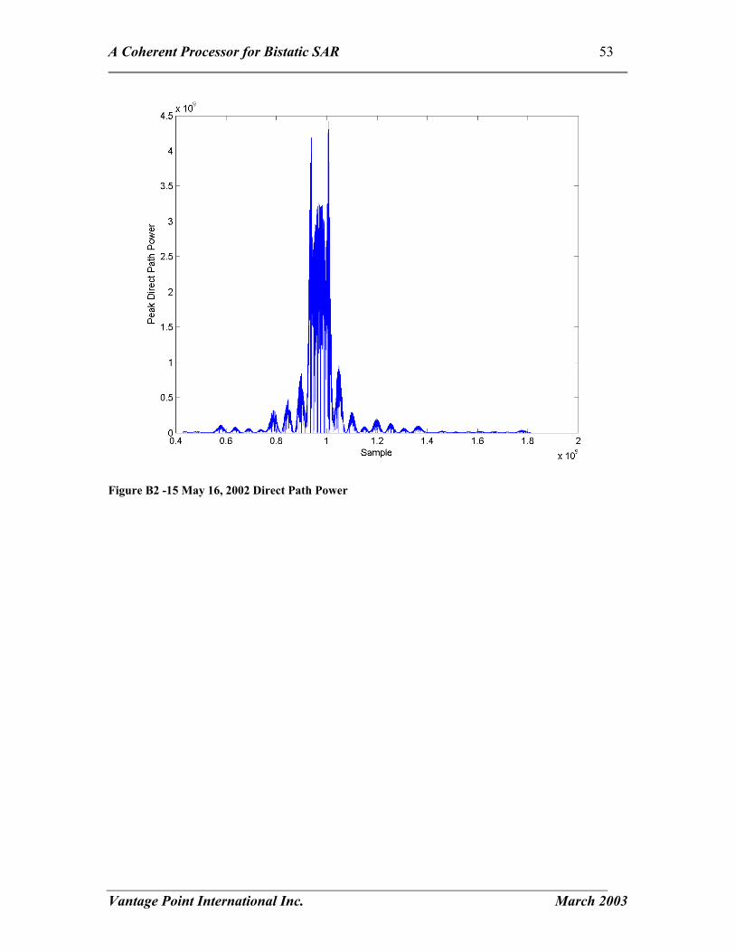
A Coherent Processor for Bistatic SAR 53
Vantage Point International Inc. March 2003
Figure B2 -15 May 16, 2002 Direct Path Power

A Coherent Processor for Bistatic SAR 54
Vantage Point International Inc. March 2003
Figure B3 - Observed effect of linear phase offset on maximum image intensity for May 16, 2002
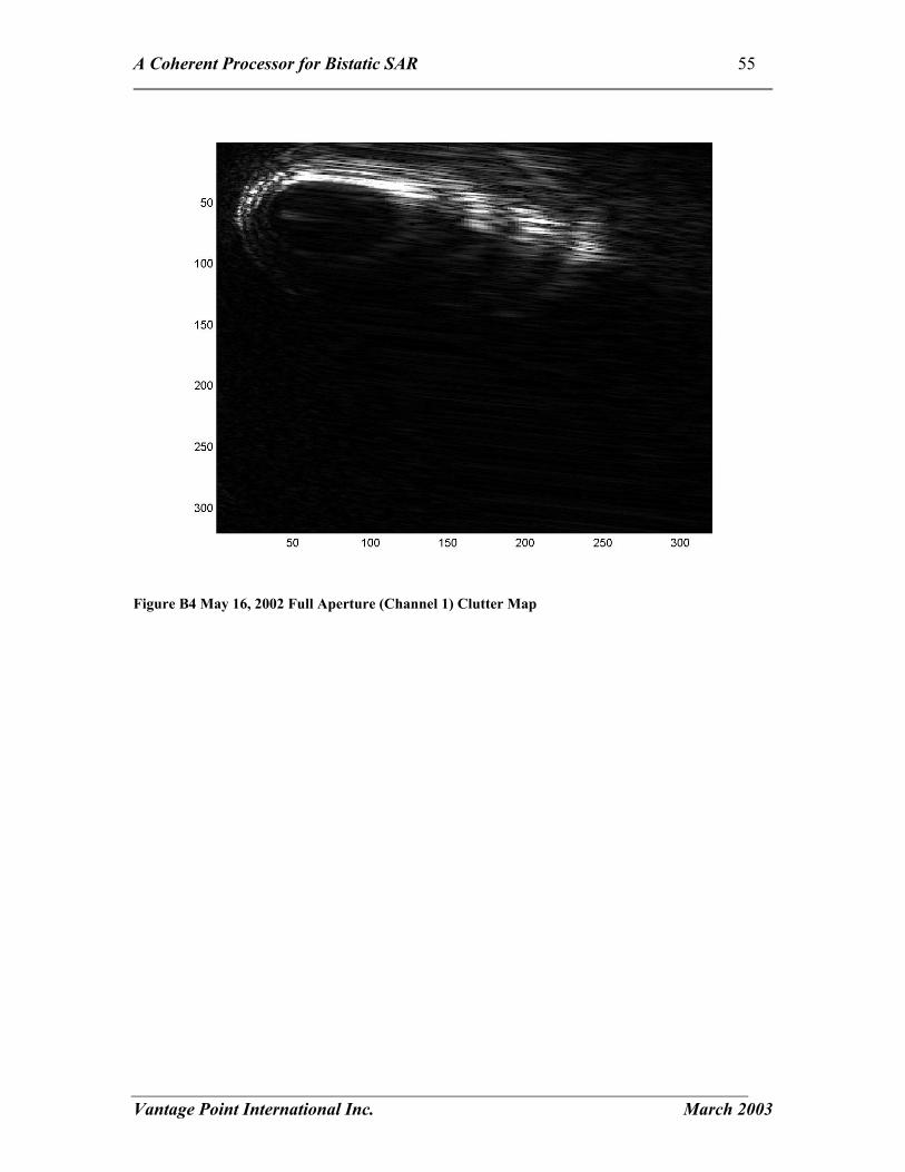
A Coherent Processor for Bistatic SAR 55
Vantage Point International Inc. March 2003
Figure B4 May 16, 2002 Full Aperture (Channel 1) Clutter Map

A Coherent Processor for Bistatic SAR 56
Vantage Point International Inc. March 2003
Figure B6 - May 16, 2002 Sub-Aperture (Channel 3) Clutter Map

A Coherent Processor for Bistatic SAR 57
Vantage Point International Inc. March 2003
Figure B7 - May 16, 2002 Sub-Aperture (Channel 4) Clutter Map
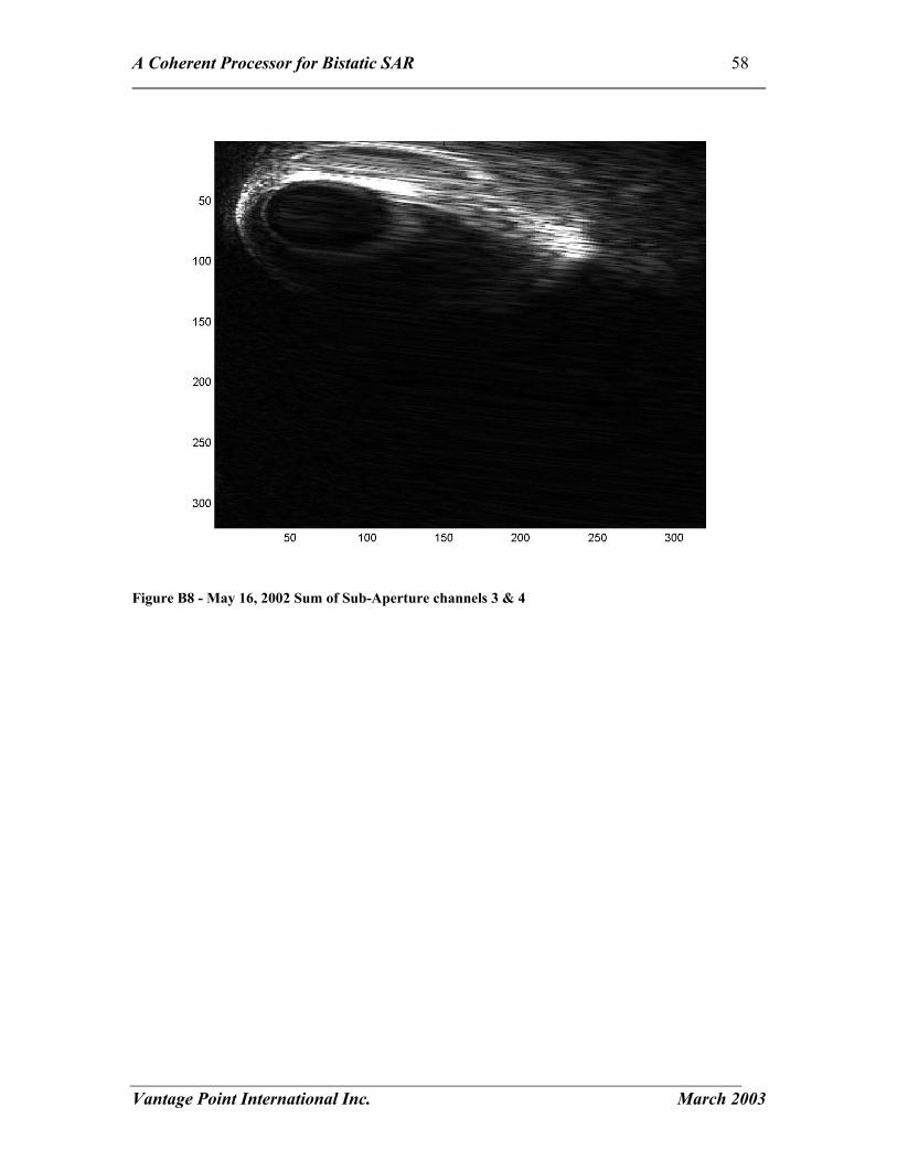
A Coherent Processor for Bistatic SAR 58
Vantage Point International Inc. March 2003
Figure B8 - May 16, 2002 Sum of Sub-Aperture channels 3 & 4
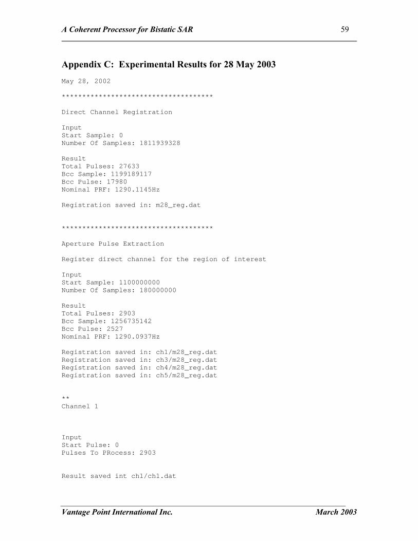
A Coherent Processor for Bistatic SAR 59
Vantage Point International Inc. March 2003
Appendix C: Experimental Results for 28 May 2003 May 28, 2002 ************************************* Direct Channel Registration Input Start Sample: 0 Number Of Samples: 1811939328 Result Total Pulses: 27633 Bcc Sample: 1199189117 Bcc Pulse: 17980 Nominal PRF: 1290.1145Hz Registration saved in: m28_reg.dat ************************************* Aperture Pulse Extraction Register direct channel for the region of interest Input Start Sample: 1100000000 Number Of Samples: 180000000 Result Total Pulses: 2903 Bcc Sample: 1256735142 Bcc Pulse: 2527 Nominal PRF: 1290.0937Hz Registration saved in: ch1/m28_reg.dat Registration saved in: ch3/m28_reg.dat Registration saved in: ch4/m28_reg.dat Registration saved in: ch5/m28_reg.dat ** Channel 1 Input Start Pulse: 0 Pulses To PRocess: 2903 Result saved int ch1/ch1.dat

A Coherent Processor for Bistatic SAR 60
Vantage Point International Inc. March 2003
** Channel 3 Input Start Pulse: 0 Pulses To PRocess: 2903 Result saved int ch3/ch3.dat ** Channel 4 Input Start Pulse: 0 Pulses To PRocess: 2903 Result saved int ch4/ch4.dat ** Channel 5 Input Start Pulse: 0 Pulses To PRocess: 2903 Result saved int ch5/ch5.dat ********************************* Linear Phase Search Input Start Frequency: 0 Stop Frequency: 1290 Frequency Step: 2 Aperture Time: 0.1 Output Best Frequency 1152 Saved linear phase search in: m28_ap0_1290hz.png ********************************* Interpolate Ground Points Initial Pixel Spacing: 325m Select: x 16 Resulting Pixel Spacing: 20.3m

A Coherent Processor for Bistatic SAR 61
Vantage Point International Inc. March 2003
****************************** Generate ground return (Clutter Map) Linear Phase Adjustment: 1152Hz Aperture time: 0.3s Save results as: ch1/m28_grnd.dat ch3/m28_grnd.dat ch4/m28_grnd.dat ch5/m28_grnd.dat ch1/m28_grnd.bmp ch3/m28_grnd.bmp ch4/m28_grnd.bmp ch5/m28_grnd.bmp
Figure C1 - Imaging Area for May 28, 2002 showing bistatic range (green) and doppler (yellow) contours.

A Coherent Processor for Bistatic SAR 62
Vantage Point International Inc. March 2003
Figure C2 - May 28, 2002 Direct Path Power

A Coherent Processor for Bistatic SAR 63
Vantage Point International Inc. March 2003
Figure C3 - Observed effect of linear phase offset on maximum image intensity for May 28, 2002

A Coherent Processor for Bistatic SAR 64
Vantage Point International Inc. March 2003
Figure C4 - May 28, 2002 Full Aperture (Channel 1) Clutter Map
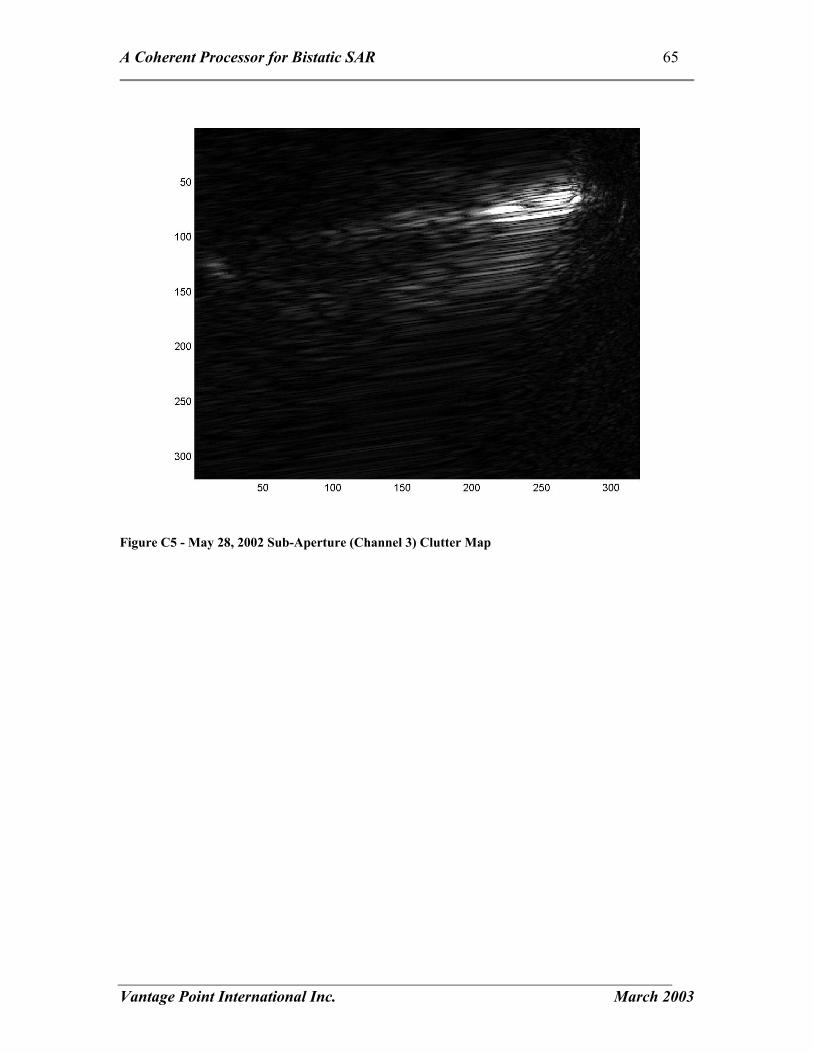
A Coherent Processor for Bistatic SAR 65
Vantage Point International Inc. March 2003
Figure C5 - May 28, 2002 Sub-Aperture (Channel 3) Clutter Map
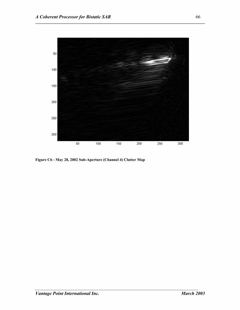
A Coherent Processor for Bistatic SAR 66
Vantage Point International Inc. March 2003
Figure C6 - May 28, 2002 Sub-Aperture (Channel 4) Clutter Map
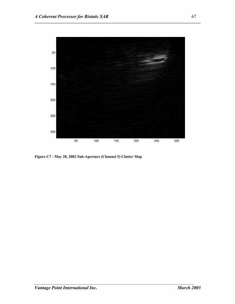
A Coherent Processor for Bistatic SAR 67
Vantage Point International Inc. March 2003
Figure C7 - May 28, 2002 Sub-Aperture (Channel 5) Clutter Map

A Coherent Processor for Bistatic SAR 68
Vantage Point International Inc. March 2003
Figure C8 - May 28, 2002 Sum of Sub-Aperture channels 3, 4 & 5

A Coherent Processor for Bistatic SAR 69
Vantage Point International Inc. March 2003
Appendix D: Listing of rangeCompressAndRegister Function ////////////////////////////////////////////////////////////////// // // Function CChannel::rangeCompressAndRegister() // // Based on the peak signal location read approximatly ### pulses // before the Bcc time of the tower. RangeCompress the signals and // register the pulses. Generate an array of PulseReturn objects // to hold the returns of each pulse for later processing. // // void CDirectChannel::rangeCompressAndRegister(CBistaticProcessor &processor) { static const int PAD_SIZE = 4096; static const int BACK_STEP = 6144; static const int SMALL_BLOCK = 4096; static const int DATA_BLOCK = 8192; int LARGE_BLOCK = (int) (processor.srate / processor.nomPRF); QuitProcess(false); bool decrement = false; CChannelDataIO &channelIO = getChannelIO(); // check for a valid channel source if (!channelIO.isOpen()) return; // check for a stop process signal DoneProcess(false); // array to hold the data complex<double> *data = new complex<double>[DATA_BLOCK]; // check for an error in alocation, should throw an exception here if (data == NULL) { DoneProcess(true); return; } // place holder for the number of samples read from channelIO int SamplesRead = 0; // vector to hold the location of the PeakSamples m_PeakSamples.clear(); m_PeakValues.clear(); numberOfSteps(StopSample() - getCurrentSample()); currentStep(getCurrentSample()); double dTotalDeltaSamples = 0; double dLargeBlock = LARGE_BLOCK; double dSampleCount = 0; int prevSample = 0; int currentPeaks = 0; while ( (getCurrentSample() < getTotalSamples()) && (getCurrentSample() < StopSample()) && !QuitProcess()) { #ifdef _DEBUG char message[100];

A Coherent Processor for Bistatic SAR 70
Vantage Point International Inc. March 2003
sprintf(message, "rangeCompressAndRegister current = %i step = %i, total = %i, pulses = %i, %i\n", getCurrentSample(), (getCurrentSample() - prevSample) , getTotalSamples(), m_PeakSamples.size(), currentPeaks); OutputDebugString(message); #endif prevSample = getCurrentSample(); // read the next block of data SamplesRead = channelIO.read(data, getCurrentSample(), DATA_BLOCK - PAD_SIZE); // zero the rest of the data for(int i = SamplesRead; i < DATA_BLOCK; i++) { data[i].real(0); data[i].imag(0); } currentPeaks = m_PeakSamples.size(); // range compress the data and get the pulse start positions processor.RangeCompress(data, DATA_BLOCK, &m_PeakSamples, &m_PeakValues); // adjust the peak sample to be from the start of the file for(int peak = currentPeaks; peak < m_PeakSamples.size(); peak++) { m_PeakSamples[peak] += getCurrentSample(); // try to adjust the LARGE_BLOCK to reflect the actual PRF if ( (m_PeakSamples.size() > 1) && (peak > 0) ) { int iSamplesBetweenPeaks = m_PeakSamples[peak] - m_PeakSamples[peak-1]; if (iSamplesBetweenPeaks < 1.5*LARGE_BLOCK) { dTotalDeltaSamples += iSamplesBetweenPeaks; dSampleCount += 1; LARGE_BLOCK = (int) dTotalDeltaSamples / dSampleCount; // use the adjusted PRF for a more stable result // check for missed peak in a null region m_PeakSamples[peak] = m_PeakSamples[peak-1] + LARGE_BLOCK; } } } // increment the current sample to search around if (m_PeakSamples.size() == currentPeaks) { // still searching for the first pulse if (decrement) { // may have over stepped the pulse setCurrentSample(getCurrentSample() - BACK_STEP); decrement = false; } else { // search forward setCurrentSample(getCurrentSample() + SMALL_BLOCK); } } else { // estimate where the next pulse will be setCurrentSample(getCurrentSample() + LARGE_BLOCK); decrement = true;

A Coherent Processor for Bistatic SAR 71
Vantage Point International Inc. March 2003
} currentStep(getCurrentSample()); } setTotalPulses(m_PeakSamples.size()); if (!QuitProcess()) { processor.nomPRF = processor.srate / LARGE_BLOCK; filterPeaks(); findBccPeak(); isRegistered(true); } delete[] data; DoneProcess(true); }

A Coherent Processor for Bistatic SAR 72
Vantage Point International Inc. March 2003
Appendix E: Listing of RangeCompress Function void CAMTIProcessor::RangeCompress(complex<double> *data, int dataSamples, vector<int> *PeakSamples, vector<double> *PeakValues) { if (dataSamples != NN) { if (match != NULL) delete[] match; NN = dataSamples; buildMatchFilter(); } if (match == NULL) return; double min = 0; double max = 0; double mean = 0; double thresh = 0; // Fourier transform the data FFT(data,NN); // multiply by the match filter for(int i=0;i<NN;i++) { data[i] *= match[i]; } // inverse Rourier transform the data. IFFT(data,NN); computeStats(data, dataSamples, &min, &max, &mean); thresh = mean*400.0; #ifdef _DEBUG // char message[100]; // sprintf(message, "Min = %f, Max = %f, Mean = %f ratio = %f\n", min, max, mean, max/mean); // OutputDebugString(message); #endif // search for signal peaks FindPeak2(data,NN,PeakValues,PeakSamples,thresh); }

A Coherent Processor for Bistatic SAR 73
Vantage Point International Inc. March 2003
Appendix F: Listing of extractPulses Function //////////////////////////////////////////////////////////////////////////////////// // // Function CChannel::extractPulses( // const vector<int> &pulseStart starting sample of each pulse to extract // // extract each of the pulses identified in the pulseStart vector // void CSubAperature::extractPulses(CBistaticProcessor &processor, const vector<int> &pulseStart, int firstPulse, int numberOfPulses) { CChannelDataIO &channelIO = getChannelIO(); // const vector<int> pulseStart = directChannel->getRegisteration(); QuitProcess(false); DoneProcess(false); static const int PULSE_BLOCK = 8192; static const int PAD_SIZE = 3360; static const int DECIMATE = 4; setPulsesToProcess(numberOfPulses); // int iBccTowerPulse = m_DirectChannel->getBccTowerPulse(); // check for a valid channel source if (!channelIO.isOpen()) return; // array to hold the data complex<double> *data = new complex<double>[PULSE_BLOCK]; int qDemodDataSize = (PULSE_BLOCK - PAD_SIZE)/DECIMATE + 1; complex<double> *qDemodData = new complex<double>[qDemodDataSize]; for(int i = 0; i < qDemodDataSize; i++) qDemodData[i] = 0; // check for an error in alocation, should throw an exception here if ( (data == NULL) || qDemodData == NULL) { if (data != NULL) delete[] data; if (qDemodData != NULL) delete[] qDemodData; DoneProcess(true); return; } // ofstream out("subap.txt"); m_Pulses.clear(); PulsesProcessed(0); setStartPulse(firstPulse); pulseOffset(firstPulse); setCurrentPulse(getStartPulse()); numberOfSteps(pulsesToProcess()); currentStep(PulsesProcessed()); // out << "Start = " << firstPulse << " " << getCurrentPulse() << '\n'; // out << "Number = " << numberOfPulses << " " << pulsesToProcess() << '\n'; int SamplesRead = 0; while ((getCurrentPulse() < pulseStart.size()) && (PulsesProcessed() < pulsesToProcess()) && !QuitProcess())

A Coherent Processor for Bistatic SAR 74
Vantage Point International Inc. March 2003
{ #ifdef _DEBUG char message[100]; sprintf(message, "extractPulses current = %i processed = %i, total to process = %i sample = %i\n", getCurrentPulse(), PulsesProcessed() , pulsesToProcess(), getCurrentSample()); OutputDebugString(message); #endif // out << getCurrentPulse() << " " << pulseStart[getCurrentPulse()] - PAD_SIZE/2 - 100 << '\n'; setCurrentSample(pulseStart[getCurrentPulse()] - PAD_SIZE/2 - 100); SamplesRead = channelIO.read(data, getCurrentSample(), PULSE_BLOCK- PAD_SIZE); // zero the rest of the data for(int i = SamplesRead; i < PULSE_BLOCK; i++) { data[i].real(0); data[i].imag(0); } // range compress the data and get the pulse start positions processor.RangeCompress(data, PULSE_BLOCK); processor.qdemod1(&data[PAD_SIZE/2], qDemodData, SamplesRead, DECIMATE); CPulseReturn p; // p.set(data, PAD_SIZE/2, SamplesRead); p.set(qDemodData, 20, SamplesRead/DECIMATE - 20); m_Pulses.push_back(p); PulsesProcessed(PulsesProcessed() + 1); currentStep(PulsesProcessed()); setCurrentPulse(getCurrentPulse() + 1); } if (data != NULL) delete[] data; if (qDemodData != NULL) delete[] qDemodData; m_bPulsesExtracted = true; // out.close(); DoneProcess(true); }

A Coherent Processor for Bistatic SAR 75
Vantage Point International Inc. March 2003
Appendix G: Listing of computeGroundReturn Function bool CBistaticProcessor::computeGroundReturn(CBistaticScenario &scenario) { DoneProcess(false); const int iNumberOfGroundPoints = scenario.getGroundPoints().GetNumberOfPoints(); const_cast<CFixedReceiver &> (scenario.getTower()).computeBccTime(scenario.getSatellite(), 0); static const double lambda = 0.0566; // metres static const double waveNumber = 1 / lambda; static const double TWOPI = 2.0 * PI; static const double OneOverTWOPI = 1 / TWOPI; static const double radiansperlambda = TWOPI / lambda; static const double rDiffToBin = (srate/c) / m_iQDemodDecimation; // sample rate / speed of light / decimation in qdemod // determine the time of interest in the scenario const double dBccTower = scenario.getTower().getBccTime(); const double dStartTime = dBccTower + (m_iStartPulse-m_DirectChannel.getBccTowerPulse())/nomPRF - 0.5; // 0.05 margin of error const double dEndTime = dStartTime + m_DirectChannel.getTotalPulses()/nomPRF + 1.0; // compute the scenario time of each pulse double *pulseTimes = new double[m_iNumberOfPulses]; double * pulseTime = NULL; if (pulseTimes == NULL) return false; else { // compute a look up table of sim times for each pulse for(int pulse = 0; pulse < m_iNumberOfPulses; pulse++) { pulseTimes[pulse] = pulseToSimTime(scenario, pulse); } } // linearPhaseAdjustment per pulse double linearPhase = linearPhaseAdjustment()/nomPRF; // create a look up table of phase values static const int PHASE_TABLE_SIZE = 4000; complex<double> Phase[PHASE_TABLE_SIZE]; for(int i = 0; i < PHASE_TABLE_SIZE; i++) { double phs = ((double) i) / ((double) PHASE_TABLE_SIZE) * 2.0 * PI; Phase[i].real(cos(phs)); Phase[i].imag(-sin(phs)); } double PhaseToIndex = PHASE_TABLE_SIZE / (2.0 * PI); complex<double> RadarReturn; // complex<double> Phase; complex<double> sum; if (!m_bLinearPhaseSearchInProgress) { numberOfSteps(iNumberOfGroundPoints); currentStep(0); } DoneProcess(false); // ofstream out("phase.dat"); // ofstream out2("bcctime.dat"); // out2 << dBccTower << '\n';

A Coherent Processor for Bistatic SAR 76
Vantage Point International Inc. March 2003
vector<CBistaticPointProperties> bistaticProperties; const CGroundPoints & groundPoints = scenario.getGroundPoints(); // for each ground point for(int point = 0; ((point < iNumberOfGroundPoints) && !QuitProcess()); point++) { if (!m_bLinearPhaseSearchInProgress) currentStep(point); CGroundPoint & gp = const_cast<CGroundPoint &> (groundPoints[point]); double dBccTime = gp.computeBistaticProperties(bistaticProperties, scenario.getTower(), scenario.getSatellite(), dStartTime, dEndTime, 0) - dBccTower; // compute the centre pulse // double dBccTime = gp.getBccTime(scenario.getSatellite(), 0) - dBccTower; int iCentrePulse = m_DirectChannel.getBccTowerPulse() + ((int) (dBccTime * nomPRF)); int iStartPulse = iCentrePulse - m_iGroundAperaturePulses/2; if (iStartPulse < 0) iStartPulse = 0; int iEndPulse = iCentrePulse + m_iGroundAperaturePulses/2; if (iEndPulse >m_DirectChannel.getTotalPulses()) iEndPulse = m_DirectChannel.getTotalPulses(); sum.real(0); sum.imag(0); pulseTime = &pulseTimes[iStartPulse]; // compute the bin that has the return from this ground point double rCentreDiff = gp.getDifferentialRange(bistaticProperties, pulseTimes[iCentrePulse]); int nCentreBin = (int) (rCentreDiff * rDiffToBin); // out2 << (dBccTime + dBccTower) << '\n'; // out2 << m_DirectChannel.getBccTowerPulse() << " " << ((int) (dBccTime * nomPRF)) << " "; // out2 << dBccTime << " " << nomPRF << '\n'; // out2 << iCentrePulse << " " << m_iGroundAperaturePulses << '\n'; // out2 << iStartPulse << " " << iEndPulse << '\n'; // loop through each extracted pulse; for(int pulse = iStartPulse; (pulse < iEndPulse); pulse++) { const CPulseReturn & pr = m_SubAperature.getPulseReturn(pulse); // compute the bin that has the return from this ground point // double rDiff = gp.getDifferentialRange(bistaticProperties, *pulseTime); // int nBin = (int) (rDiff * rDiffToBin); // copy the return value to an array of return values // RadarReturn = pr[nBin]; RadarReturn = pr[nCentreBin]; // out2 << pulse << " " << RadarReturn.real() << " " << RadarReturn .imag() << '\n'; // take the complex conjugate // RadarReturn.imag(-1.0 * RadarReturn.imag()); // compute expected phase of return based on the difference between // the direct path (satellite-tower) and the bistatic path (satellite-ground-tower) // save the value in an array double rBistatic = gp.getRange(bistaticProperties, *pulseTime); double numberOfWavelengths = rBistatic * waveNumber; /// lambda;

A Coherent Processor for Bistatic SAR 77
Vantage Point International Inc. March 2003
// linear phase adjustment //double linearPhaseCycles = (pulse - iStartPulse) * linearPhase / TWOPI; double linearPhaseCycles = pulse * linearPhase * OneOverTWOPI; // / TWOPI; // only here for debugging double Cycles = numberOfWavelengths + linearPhaseCycles; double fractionOfCycle = (Cycles - ((int) Cycles)); double phase = fractionOfCycle * TWOPI; int phaseIndex = (int) (phase * PhaseToIndex); if (phaseIndex >= PHASE_TABLE_SIZE) phaseIndex -= PHASE_TABLE_SIZE; if (phaseIndex < 0) phaseIndex += PHASE_TABLE_SIZE; sum += RadarReturn * Phase[phaseIndex]; // increment the pointer to the next pulse time pulseTime++; // if (point == 0) // { // char message[100]; // sprintf(message, "%f %f %f %f\n", rBistatic, numberOfWavelengths, fractionOfWavelengths, fractionOfWavelengths2); // out << message; // } } #ifdef _DEBUG char message[100]; if (!m_bLinearPhaseSearchInProgress) { sprintf(message, "Point = %i, pulse = %i, sum.real = %f, sum.imag = %f\n", point, pulse, sum.real(), sum.imag()); OutputDebugString(message); } #endif // Save this result as th return value gp.Return(sum); bistaticProperties.clear(); } // out.close(); // out2.close(); delete[] pulseTimes; // DoneProcess(true); GroundReturnProcessed(true); return true; }

UNCLASSIFIED SECURITY CLASSIFICATION OF FORM
(highest classification of Title, Abstract, Keywords)
DOCUMENT CONTROL DATA (Security classification of title, body of abstract and indexing annotation must be entered when the overall document is classified)
1. ORIGINATOR (the name and address of the organization preparing the document. Organizations for whom the document was prepared, e.g. Establishment sponsoring a contractor’s report, or tasking agency, are entered in section 8.)
Vantage Point International 1704 Carling Avenue, 2nd Floor, Ottawa, K2A 1C7
2. SECURITY CLASSIFICATION (overall security classification of the document,
including special warning terms if applicable) UNCLASSIFIED
3. TITLE (the complete document title as indicated on the title page. Its classification should be indicated by the appropriate abbreviation (S,C or U) in parentheses after the title.)
(U) A Coherent Processor for Bistatic Synthetic Aperture Radar
4. AUTHORS (Last name, first name, middle initial)
C. williams, M. St.-Hilaire and R. Saper
5. DATE OF PUBLICATION (month and year of publication of document)
March 2003
6a. NO. OF PAGES (total containing information. Include Annexes, Appendices, etc.)
77
6b. NO. OF REFS (total cited in document)
4
7. DESCRIPTIVE NOTES (the category of the document, e.g. technical report, technical note or memorandum. If appropriate, enter the type of report, e.g. interim, progress, summary, annual or final. Give the inclusive dates when a specific reporting period is covered.)
Contractor Report
8. SPONSORING ACTIVITY (the name of the department project office or laboratory sponsoring the research and development. Include the address.)
DRDC Ottawa, 3701 Carling Avenue, Ottawa, ON K2A 0Z4
9a. PROJECT OR GRANT NO. (if appropriate, the applicable research and development project or grant number under which the document was written. Please specify whether project or grant)
15ES16
9b. CONTRACT NO. (if appropriate, the applicable number under which the document was written)
W7714-020667/001/SV
10a. ORIGINATOR’S DOCUMENT NUMBER (the official document number by which the document is identified by the originating activity. This number must be unique to this document.)
10b. OTHER DOCUMENT NOS. (Any other numbers which may be assigned this document either by the originator or by the sponsor)
DRDC Ottawa CR 2003-036
11. DOCUMENT AVAILABILITY (any limitations on further dissemination of the document, other than those imposed by security classification) ( x ) Unlimited distribution ( ) Distribution limited to defence departments and defence contractors; further distribution only as approved ( ) Distribution limited to defence departments and Canadian defence contractors; further distribution only as approved ( ) Distribution limited to government departments and agencies; further distribution only as approved ( ) Distribution limited to defence departments; further distribution only as approved ( ) Other (please specify):
12. DOCUMENT ANNOUNCEMENT (any limitation to the bibliographic announcement of this document. This will normally correspond to
the Document Availability (11). However, where further distribution (beyond the audience specified in 11) is possible, a wider announcement audience may be selected.)
UNCLASSIFIED
SECURITY CLASSIFICATION OF FORM DDCCDD0033 22//0066//8877

UNCLASSIFIED SECURITY CLASSIFICATION OF FORM
13. ABSTRACT ( a brief and factual summary of the document. It may also appear elsewhere in the body of the document itself. It is highly desirable that the abstract of classified documents be unclassified. Each paragraph of the abstract shall begin with an indication of the security classification of the information in the paragraph (unless the document itself is unclassified) represented as (S), (C), or (U). It is not necessary to include here abstracts in both official languages unless the text is bilingual).
Under this project, a relatively sophisticated Bistatic SAR Processor was successfully developed in Microsoft Visual C++ 6.0 under Windows 2000. The processor handles alignment of the data using the direct path data, automatic estimation of the receiver beam center crossing time (BCC), range compression of the reflected path data and phase history compression of the reflected path data.
14. KEYWORDS, DESCRIPTORS or IDENTIFIERS (technically meaningful terms or short phrases that characterize a document and could be helpful in cataloguing the document. They should be selected so that no security classification is required. Identifiers such as equipment model designation, trade name, military project code name, geographic location may also be included. If possible keywords should be selected from a published thesaurus. e.g. Thesaurus of Engineering and Scientific Terms (TEST) and that thesaurus-identified. If it is not possible to select indexing terms which are Unclassified, the classification of each should be indicated as with the title.)
Bistatic SAR processing, Bistatic radar, joint experiment
UNCLASSIFIED
SECURITY CLASSIFICATION OF FORM