juha loponen creation of abb microscada database tool · microscada installation on the...
TRANSCRIPT
Juha Loponen
CREATION OF ABB MICROSCADA
DATABASE TOOL
School of Technology
2018
VAASAN AMMATTIKORKEAKOULU
Sähkötekniikka
TIIVISTELMÄ
Tekijä Juha Loponen
Opinnäytetyön nimi Creation of ABB MicroSCADA Database Tool
Vuosi 2018
Kieli englanti
Sivumäärä 31
Ohjaaja Jari Koski
Tämän opinnäytetyöprojektin tarkoitus on luoda uusi työkalu MicroSCADA tieto-
kantojen luomiseen. Nykyiset apuohjelmat eivät ole ajan tasalla projektien laajuu-
den ja käyttäjäystävällisyyden kanssa.
Uusi työkalu haluttiin riippumattomaksi MicroSCADAn asennuksesta käyttäjän
työskentelytietokoneessa sekä selkeyttää tietokantapisteiden luomista listapohjai-
sessa työympäristössä. Uuden työkalun käyttäjäystävällisyyteen panostettiin lisää-
mällä laajat tarkistusominaisuudet. Tarkastaminen toteutettiin listaamalla tietokan-
tapisteiden oletusarvoja ja vertaamalla niitä ja käyttäjän syötettä. Työkalu toteutet-
tiin Microsoft Exceliin luoduilla Visual Basic for Applications -koodeilla.
Työkalu on tehokas ja siinä on selkeä käyttäjä-rajapinta. Se on parhaimmillaan
isoissa projekteissa, joissa on paljon samankaltaisia signaaleja eri asemilla ja läh-
döillä.
Avainsanat MicroSCADA, tietokanta, luonti, Excel
VAASAN AMMATTIKORKEAKOULU
UNIVERSITY OF APPLIED SCIENCES
Sähkötekniikka
ABSTRACT
Author Juha Loponen
Title Creation of ABB MicroSCADA Database Tool
Year 2018
Language English
Pages 31
Name of Supervisor Jari Koski
The aim of this final thesis project was to create a new tool for creating Mi-
croSCADA databases. The current means of database creation are not up to date
with the workload of the projects and the user-friendliness standards.
There was a desire to get the tool as an independent program that does not need a
MicroSCADA installation on the engineering-PC and to clarify the process of cre-
ating database objects in list based environment. The user-friendliness was a key
aspect in creating the new tool and it was done by adding a vast checking system to
the tool by listing default values of database objects and comparing user inputs to
them. The tool was created in Microsoft Excel with the Visual Basic for Application
–code.
The new tool is efficient and has a clear user interface. It is most useful in big pro-
jects with many similar signals in different stations and bays.
Keywords MicroSCADA, database, creation and Excel
TABLE OF CONTENTS
TIIVISTELMÄ
ABSTRACT
INTRODUCTION .................................................................................................. 6
1 ABB .................................................................................................................. 7
1.1 ABB Grid Automation and MicroSCADA ............................................... 7
2 BACKGROUND AND THE NEED FOR A NEW TOOL ............................. 8
2.1 Standard Function ..................................................................................... 8
2.2 LBE tool .................................................................................................. 14
3 CREATING NEW DATABASE TOOL ........................................................ 17
3.1 Requirements of New Tool ..................................................................... 17
3.2 Designing SCADA Interface and User Interface .................................... 17
3.3 Functionalities and validations ............................................................... 19
3.3.1 Validate ....................................................................................... 19
3.3.2 Clear Log ..................................................................................... 22
3.3.3 Select output path ........................................................................ 23
3.3.4 Create Files.................................................................................. 24
4 TESTING ....................................................................................................... 25
4.1 Testing of Database Tool ........................................................................ 25
4.2 Testing the Interface with MicroSCADA ............................................... 27
4.3 Testing the Actual Use of Database Objects in MicroSCADA .............. 27
5 CONCLUSIONS ............................................................................................ 30
REFERENCES ...................................................................................................... 31
5
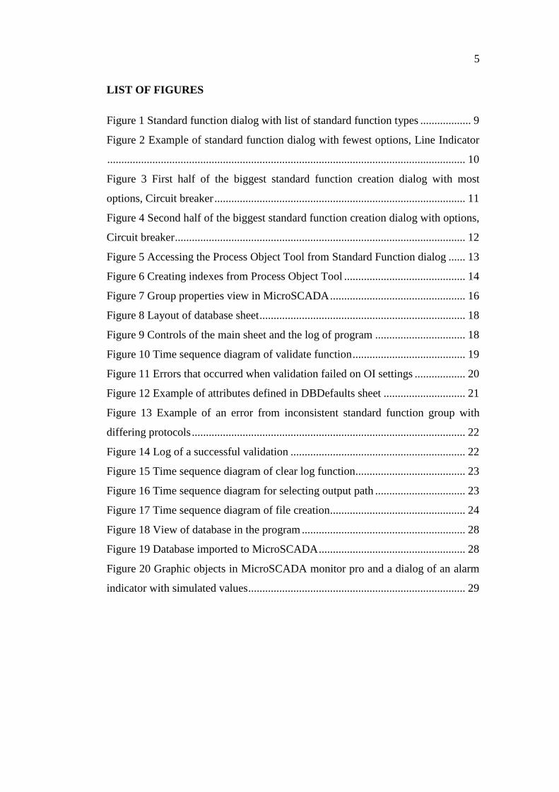
LIST OF FIGURES
Figure 1 Standard function dialog with list of standard function types .................. 9
Figure 2 Example of standard function dialog with fewest options, Line Indicator
............................................................................................................................... 10
Figure 3 First half of the biggest standard function creation dialog with most
options, Circuit breaker ......................................................................................... 11
Figure 4 Second half of the biggest standard function creation dialog with options,
Circuit breaker ....................................................................................................... 12
Figure 5 Accessing the Process Object Tool from Standard Function dialog ...... 13
Figure 6 Creating indexes from Process Object Tool ........................................... 14
Figure 7 Group properties view in MicroSCADA ................................................ 16
Figure 8 Layout of database sheet ......................................................................... 18
Figure 9 Controls of the main sheet and the log of program ................................ 18
Figure 10 Time sequence diagram of validate function ........................................ 19
Figure 11 Errors that occurred when validation failed on OI settings .................. 20
Figure 12 Example of attributes defined in DBDefaults sheet ............................. 21
Figure 13 Example of an error from inconsistent standard function group with
differing protocols ................................................................................................. 22
Figure 14 Log of a successful validation .............................................................. 22
Figure 15 Time sequence diagram of clear log function....................................... 23
Figure 16 Time sequence diagram for selecting output path ................................ 23
Figure 17 Time sequence diagram of file creation................................................ 24
Figure 18 View of database in the program .......................................................... 28
Figure 19 Database imported to MicroSCADA .................................................... 28
Figure 20 Graphic objects in MicroSCADA monitor pro and a dialog of an alarm
indicator with simulated values ............................................................................. 29
6
INTRODUCTION
The aim of this final thesis project is to design and create new database creation
tool for MicroSCADA for ABB Grid Automation Systems project team.
Existing means of creating and modifying databases especially on larger projects
are not efficient. Projects with many signals are common to have changes during
the projecting period and can cause unnecessary extra work in projects.
Creating a working, efficient and user-friendly tool can help project engineers do
less of inefficient but commonly occurring work with the modification of database
in cases, such as changed naming policies or adding or changing of signals. With
the ease of modifying and then creating a new correct database it is possible to save
engineering hours needed to complete projects.
7
1 ABB
ABB was founded in 1988 as a result of a fusion between the electrical technologies
of Swedish Asea and Swiss Brown Boveri. Today ABB is a pioneer of technology
with a wide portfolio from robotics to grid solutions. ABB operates in more than
100 countries and employs around 136000 people. ABB headquarters are in Zurich,
Switzerland. ABB is divided in four Business units, which are Electrification prod-
ucts, Robotics and motion, Industrial automation and Power grids. /1-3/
ABB has 5100 people working in Finland and operates in 20 cities and towns. The
main factory areas are in Hamina, Helsinki, Vaasa and Porvoo. ABB is one of the
biggest employers in technical field in Finland and the biggest in Helsinki area. The
revenue is around 2.2 billion euros. /4/
1.1 ABB Grid Automation and MicroSCADA
The Grid Automation business unit is part of ABB Power Grids division. Globally
Grid Automation business unit employs around 4000 people and 60 in Finland. Grid
Automation unit sells and uses MicroSCADA in projects. /5-6/
MicroSCADA name comes from Supervisory Control And Data Acquisition. It is
a system that uses graphical interfaces, computer and networked communication
for system control and management. MicroSCADA Pro is designed for complete
functionality for real-time monitoring and control of primary and secondary equip-
ment in transmission and distribution substations. It allows you to easily and safely
interact with protection and control IEDs (intelligent electronic device), as well as
with the process via the operator’s workplace. /7/

8
2 BACKGROUND AND THE NEED FOR A NEW TOOL
Currently there are two main ways to create database: Standard function tool in
MicroSCADA and LBE-tool (List based engineering) based on Excel which uses
OPC connection to MicroSCADA. Projects have been growing in terms of number
of signals and data that is being handled by MicroSCADA. The technical develop-
ment of IED’s and other field devices make the existing means of database creation
and modification lacklustre in performance. This development project aims to com-
bine the best means of current options and remove the issues that make them not
ideal in the projects of today. The new database tool is designed and aimed to help
project engineers to create and modify big projects with many signals with ease.
2.1 Standard Function
The Standard Function tool is an internal tool of MicroSCADA that creates all the
necessary indexes and thus automatically fills all the database attributes the Mi-
croSCADA needs to work properly. The user can choose his desired standard func-
tion type and the defining selections through dialogs, which can be accessed
through the Object navigator in MicroSCADA tools. The devices that the user can
create with the Standard Function tool are:
Station
Bay
Switching Device
Tap Changer
Measurement
Alarm Indicator
Auto Reclose
Trip Signal
Generator
Line Indicator
9
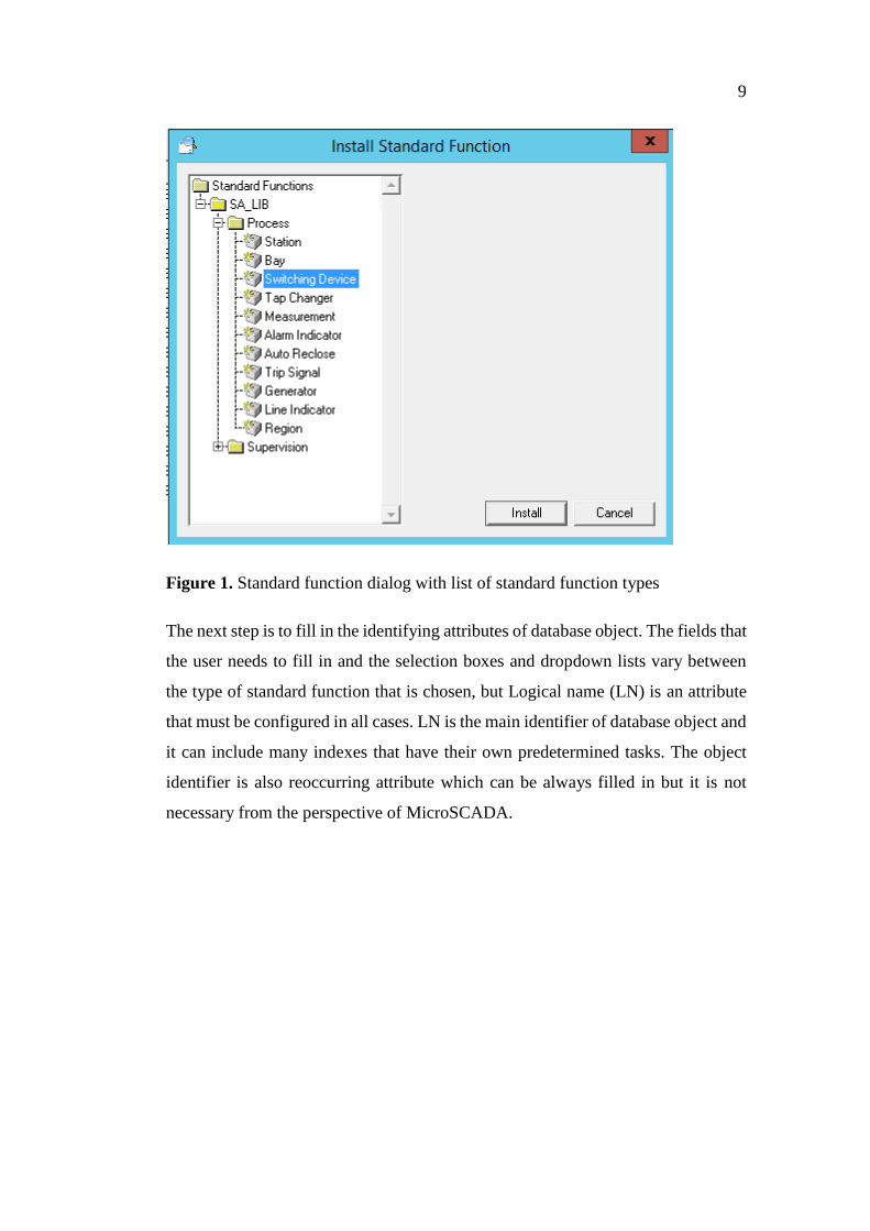
Figure 1. Standard function dialog with list of standard function types
The next step is to fill in the identifying attributes of database object. The fields that
the user needs to fill in and the selection boxes and dropdown lists vary between
the type of standard function that is chosen, but Logical name (LN) is an attribute
that must be configured in all cases. LN is the main identifier of database object and
it can include many indexes that have their own predetermined tasks. The object
identifier is also reoccurring attribute which can be always filled in but it is not
necessary from the perspective of MicroSCADA.
10
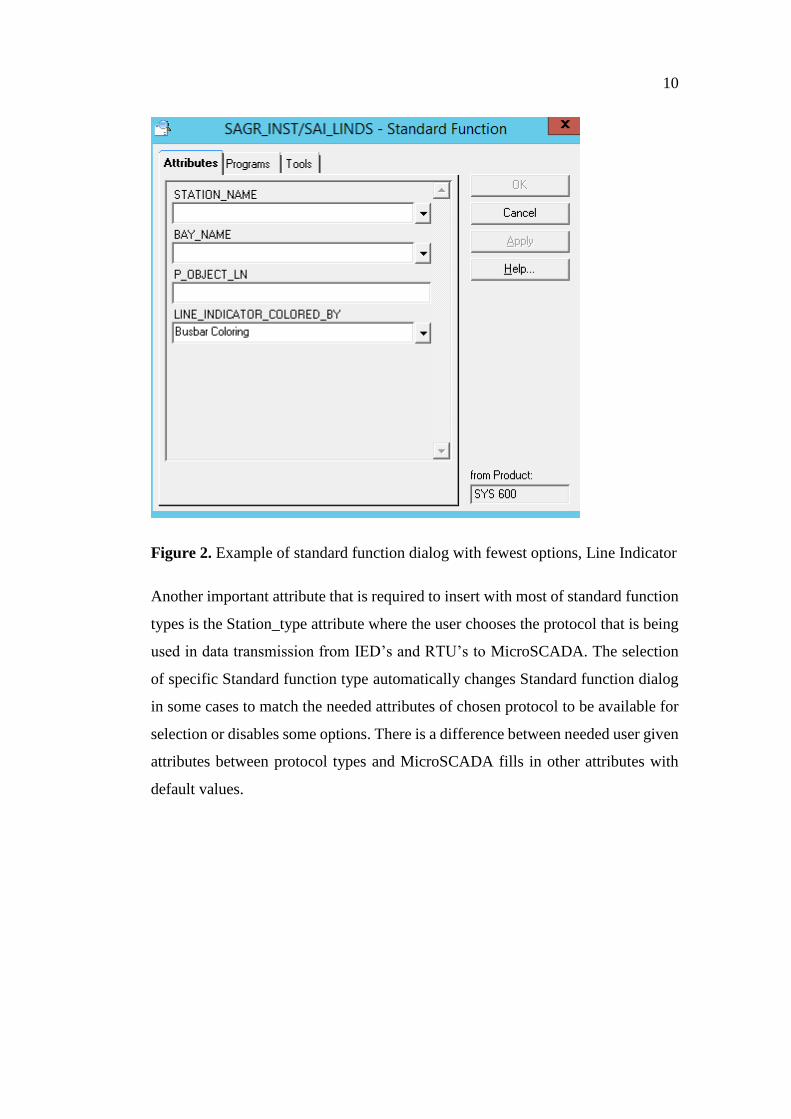
Figure 2. Example of standard function dialog with fewest options, Line Indicator
Another important attribute that is required to insert with most of standard function
types is the Station_type attribute where the user chooses the protocol that is being
used in data transmission from IED’s and RTU’s to MicroSCADA. The selection
of specific Standard function type automatically changes Standard function dialog
in some cases to match the needed attributes of chosen protocol to be available for
selection or disables some options. There is a difference between needed user given
attributes between protocol types and MicroSCADA fills in other attributes with
default values.
11
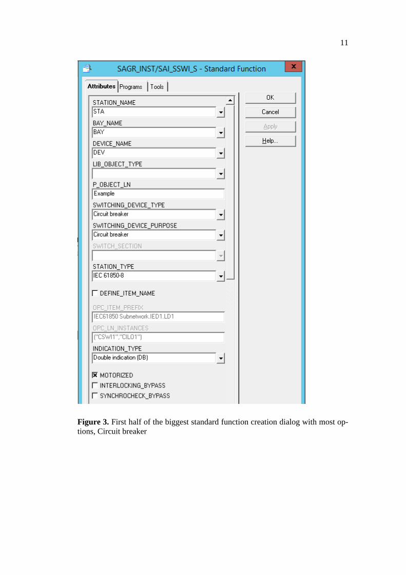
Figure 3. First half of the biggest standard function creation dialog with most op-
tions, Circuit breaker
12
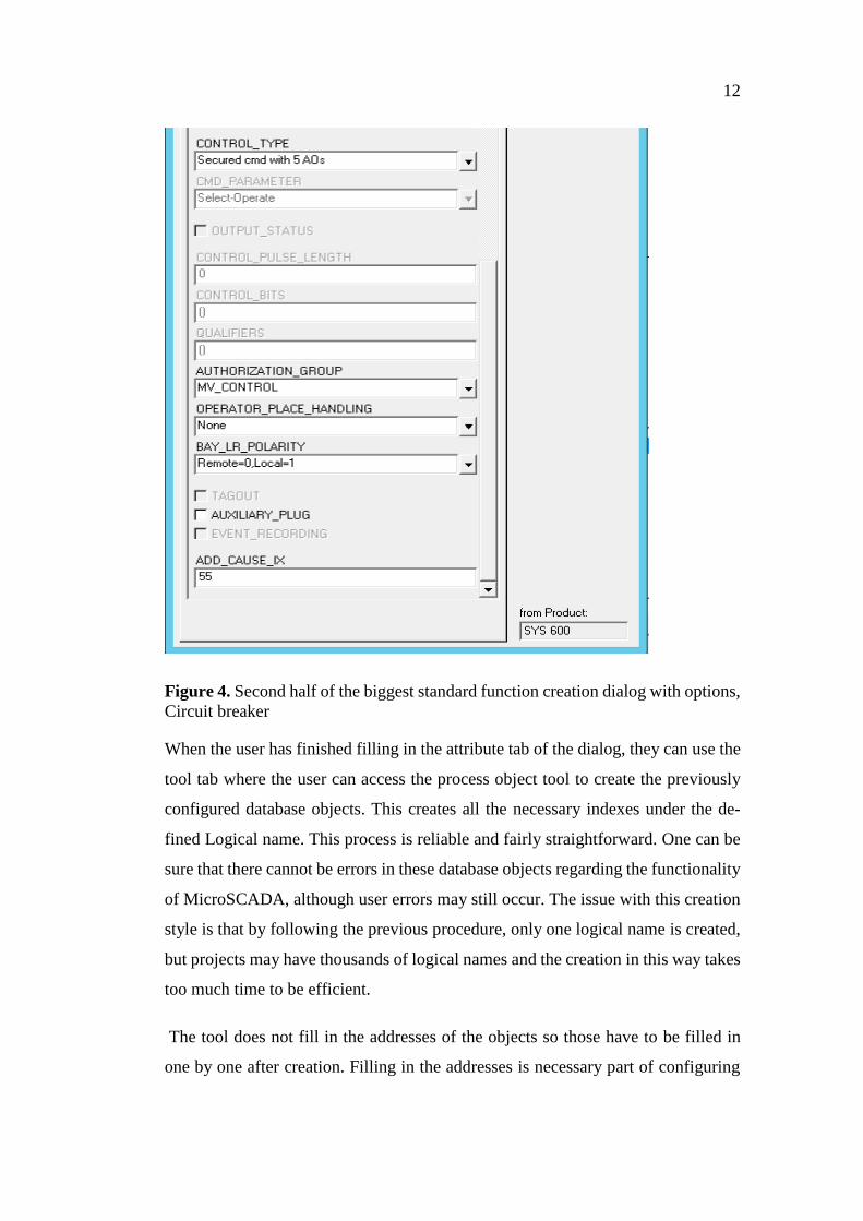
Figure 4. Second half of the biggest standard function creation dialog with options,
Circuit breaker
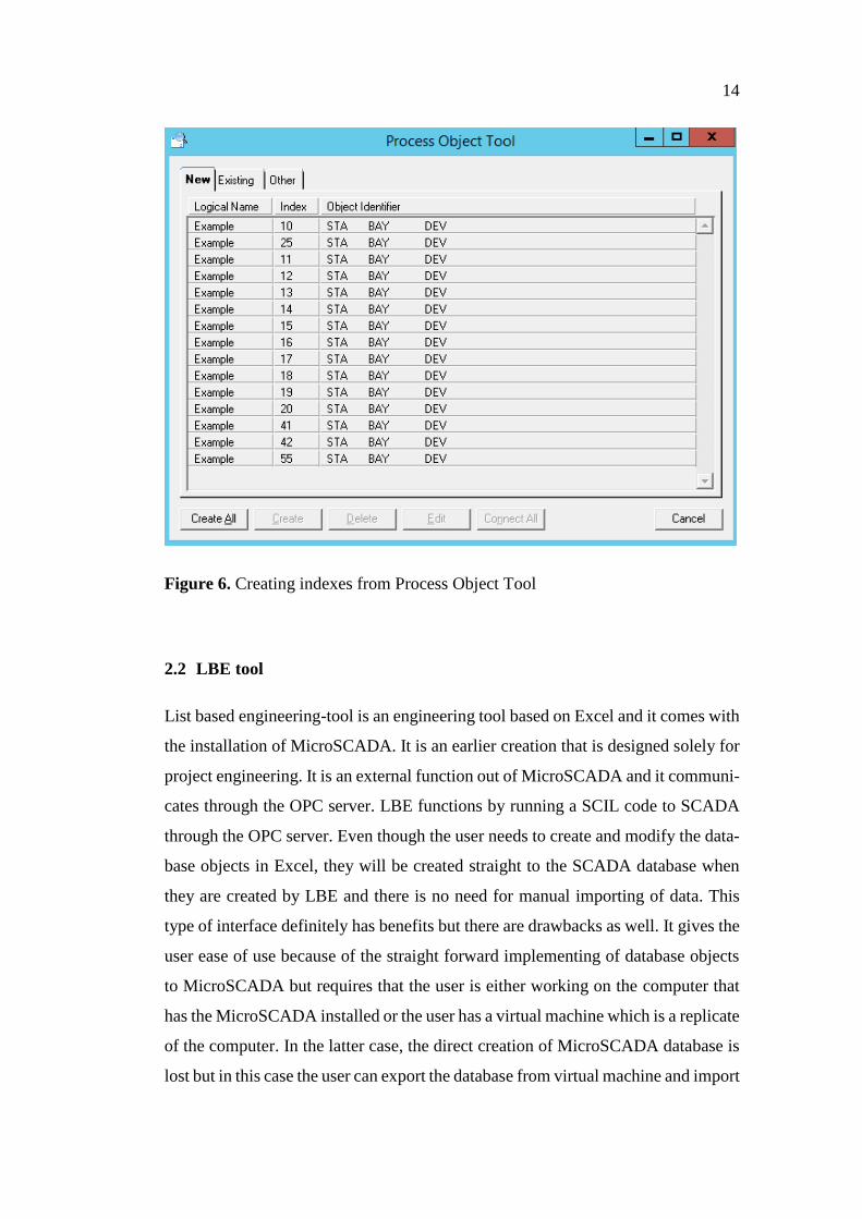
When the user has finished filling in the attribute tab of the dialog, they can use the
tool tab where the user can access the process object tool to create the previously
configured database objects. This creates all the necessary indexes under the de-
fined Logical name. This process is reliable and fairly straightforward. One can be
sure that there cannot be errors in these database objects regarding the functionality
of MicroSCADA, although user errors may still occur. The issue with this creation
style is that by following the previous procedure, only one logical name is created,
but projects may have thousands of logical names and the creation in this way takes
too much time to be efficient.
The tool does not fill in the addresses of the objects so those have to be filled in
one by one after creation. Filling in the addresses is necessary part of configuring
13
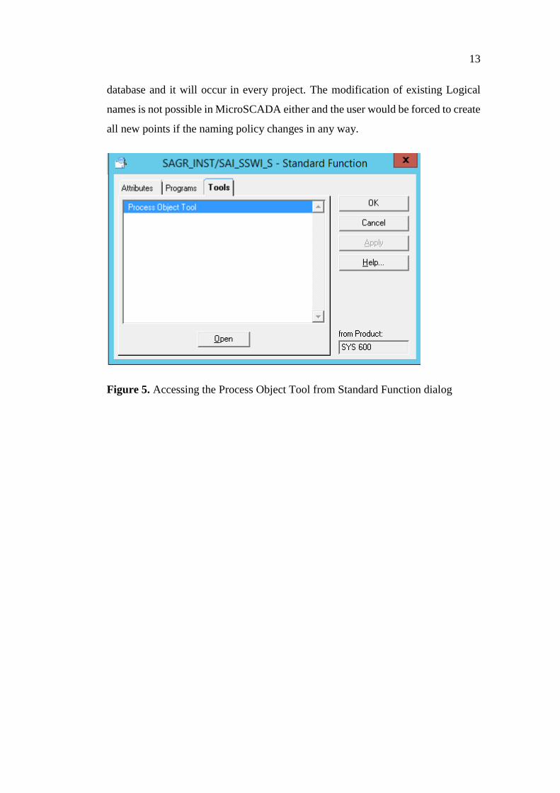
database and it will occur in every project. The modification of existing Logical
names is not possible in MicroSCADA either and the user would be forced to create
all new points if the naming policy changes in any way.
Figure 5. Accessing the Process Object Tool from Standard Function dialog
14
Figure 6. Creating indexes from Process Object Tool
2.2 LBE tool
List based engineering-tool is an engineering tool based on Excel and it comes with
the installation of MicroSCADA. It is an earlier creation that is designed solely for
project engineering. It is an external function out of MicroSCADA and it communi-
cates through the OPC server. LBE functions by running a SCIL code to SCADA
through the OPC server. Even though the user needs to create and modify the data-
base objects in Excel, they will be created straight to the SCADA database when
they are created by LBE and there is no need for manual importing of data. This
type of interface definitely has benefits but there are drawbacks as well. It gives the
user ease of use because of the straight forward implementing of database objects
to MicroSCADA but requires that the user is either working on the computer that
has the MicroSCADA installed or the user has a virtual machine which is a replicate
of the computer. In the latter case, the direct creation of MicroSCADA database is
lost but in this case the user can export the database from virtual machine and import
15
it to the server. When using this method on servers, it requires that Excel is installed
on the server and that adds an unnecessary cost to projects.
LBE is better option than the Standard function tool to create mass of database ob-
jects as it makes it easier to copy and multiply database objects. When the user has
completed one row which means creating one logical name with all indexes, the
user can copy and paste the row and just by changing LN he can multiply signals.
This is very useful in bigger projects with many signals of the same type. One of
the disadvantages in the LBE layout is that all of the indexes of LN are on the same
row and the modification of indexes can be disorientating and the user mistakes are
easy to make when adding new indexes. This means that the user must add all the
needed attributes of the indexes to the same row. It is easy for the user to make
corrections to a wrong row because the logical name and the attributes the user
wants to correct cannot be visible at the same time in most of the cases due to the
way the layout and indexes are modified in LBE.
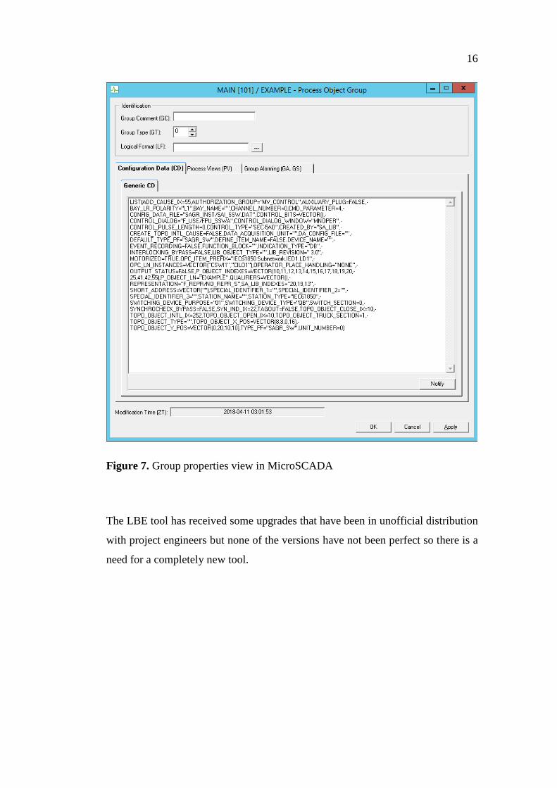
Using LBE is not as simple as using the standard function tool. Prior to creating any
points in LBE the user must create examples of the standard function types he wants
to use. When viewing the group properties of the EXAMPLE database objects cre-
ated before the attributes that are necessary to fill in the LBE can be seen.
16
Figure 7. Group properties view in MicroSCADA
The LBE tool has received some upgrades that have been in unofficial distribution
with project engineers but none of the versions have not been perfect so there is a
need for a completely new tool.
17
3 CREATING NEW DATABASE TOOL
3.1 Requirements of New Tool
The goal for the new tool is that the functionalities it possess should outperform the
existing means of database creation. The list below shows the aspects that were
thought of when thinking what the new tool should ideally be able to fulfil.
More streamlined list based modification
More explanatory information to help the user fill in values
MicroSCADA installation on engineering PC is not mandatory
Comprehensive user input validation to mitigate errors
Error handling and help on solving errors
Exports database from MicroSCADA in to the tool
Use existing interface for data transfer between MicroSCADA and tool
3.2 Designing SCADA Interface and User Interface
The planning of the new tool started from selecting the interface, how the database
is moved from our tool to the MicroSCADA. Going through the options of import-
ing and exporting databases of MicroSCADA, the CSV (Comma separated value)
import through Import/export tool was selected as the most efficient mean. The
CSV files are easy to create with Excel and the MicroSCADA support for CSV
import is not expected to be removed from MicroSCADA tools in future updates.
Import/export tool will be kept up to date in future updates.
When using CSV files, the program will create more than one Excel file, the header
file which tells SCADA what type of other CSV files it has to read. Types that can
be included are all of the different signal types: AI, AO, BI, BO, BS, DB, DI, DO,
PC and a so-called P-file, which has the standard function specific CD attributes.
All of the different signal types are included in their own file. If some type of signal
is not used, the file for that type will not be created. /8/
The next step was designing the user interface and layout with the desire to create
a familiar looking interface. The aim was to create a layout where it is clear to the
18
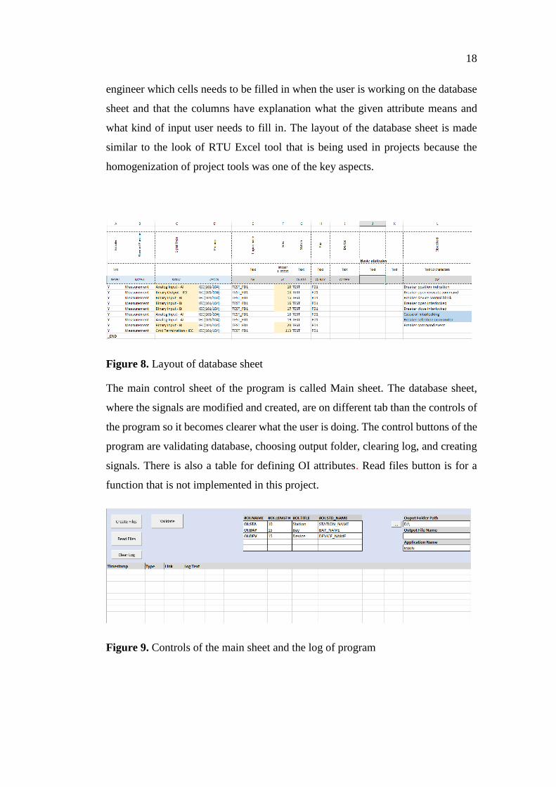
engineer which cells needs to be filled in when the user is working on the database
sheet and that the columns have explanation what the given attribute means and
what kind of input user needs to fill in. The layout of the database sheet is made
similar to the look of RTU Excel tool that is being used in projects because the
homogenization of project tools was one of the key aspects.
Figure 8. Layout of database sheet
The main control sheet of the program is called Main sheet. The database sheet,
where the signals are modified and created, are on different tab than the controls of
the program so it becomes clearer what the user is doing. The control buttons of the
program are validating database, choosing output folder, clearing log, and creating
signals. There is also a table for defining OI attributes. Read files button is for a
function that is not implemented in this project.
Figure 9. Controls of the main sheet and the log of program
19
3.3 Functionalities and validations
All of the functionalities of the program have been done in the VBA (Visual Basic
for Applications). Basic functionalities, such as clearing error log and choosing out-
put folder are solely code but validating and creating the CSV files rely also on data
tables filled with the default values of MicroSCADA attributes and examples of
Standard functions.
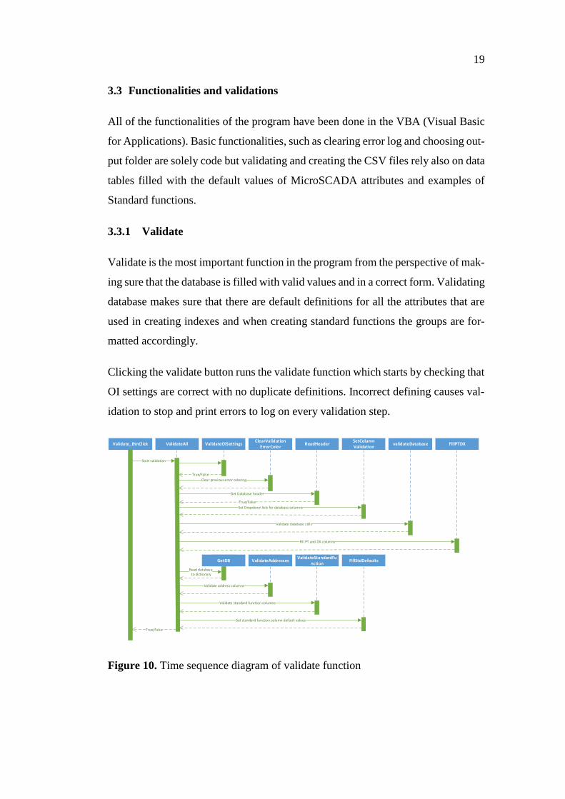
3.3.1 Validate
Validate is the most important function in the program from the perspective of mak-
ing sure that the database is filled with valid values and in a correct form. Validating
database makes sure that there are default definitions for all the attributes that are
used in creating indexes and when creating standard functions the groups are for-
matted accordingly.
Clicking the validate button runs the validate function which starts by checking that
OI settings are correct with no duplicate definitions. Incorrect defining causes val-
idation to stop and print errors to log on every validation step.
Validate_BtnClick ValidateAll ReadHeader
Start validation
Get Database header
validateDatabase FillPTDX
True/False
True/False
ValidateOiSettings
True/False
ClearValidationErrorColor
SetColumnValidation
GetDB ValidateAddressesValidateStandardFu
nctionFillStdDefaults
Clear previous error coloring
Set Dropdown lists for database columns
Validate database cells
Fill PT and DX columns
Read database to dictionary
Validate address columns
Validate standard function columns
Set standard function column default values
Figure 10. Time sequence diagram of validate function
20
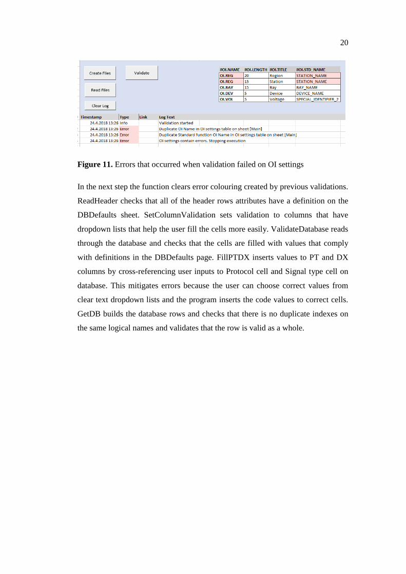
Figure 11. Errors that occurred when validation failed on OI settings
In the next step the function clears error colouring created by previous validations.
ReadHeader checks that all of the header rows attributes have a definition on the
DBDefaults sheet. SetColumnValidation sets validation to columns that have
dropdown lists that help the user fill the cells more easily. ValidateDatabase reads
through the database and checks that the cells are filled with values that comply
with definitions in the DBDefaults page. FillPTDX inserts values to PT and DX
columns by cross-referencing user inputs to Protocol cell and Signal type cell on
database. This mitigates errors because the user can choose correct values from
clear text dropdown lists and the program inserts the code values to correct cells.
GetDB builds the database rows and checks that there is no duplicate indexes on
the same logical names and validates that the row is valid as a whole.
21
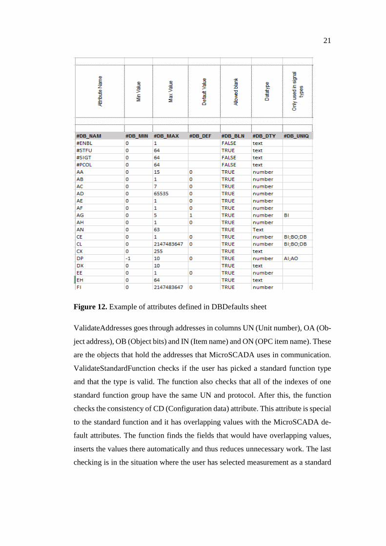
Figure 12. Example of attributes defined in DBDefaults sheet
ValidateAddresses goes through addresses in columns UN (Unit number), OA (Ob-
ject address), OB (Object bits) and IN (Item name) and ON (OPC item name). These
are the objects that hold the addresses that MicroSCADA uses in communication.
ValidateStandardFunction checks if the user has picked a standard function type
and that the type is valid. The function also checks that all of the indexes of one
standard function group have the same UN and protocol. After this, the function
checks the consistency of CD (Configuration data) attribute. This attribute is special
to the standard function and it has overlapping values with the MicroSCADA de-
fault attributes. The function finds the fields that would have overlapping values,
inserts the values there automatically and thus reduces unnecessary work. The last
checking is in the situation where the user has selected measurement as a standard
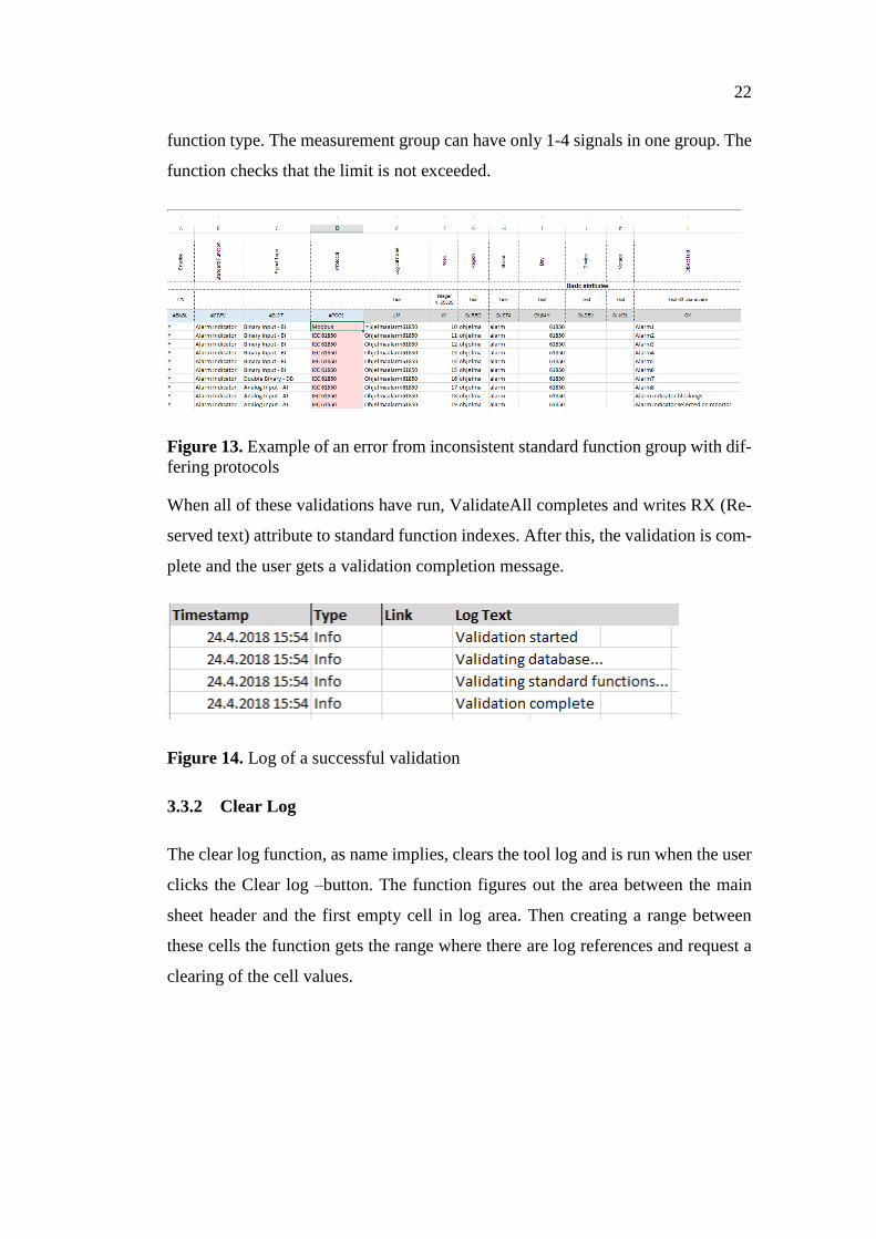
22
function type. The measurement group can have only 1-4 signals in one group. The
function checks that the limit is not exceeded.
Figure 13. Example of an error from inconsistent standard function group with dif-
fering protocols
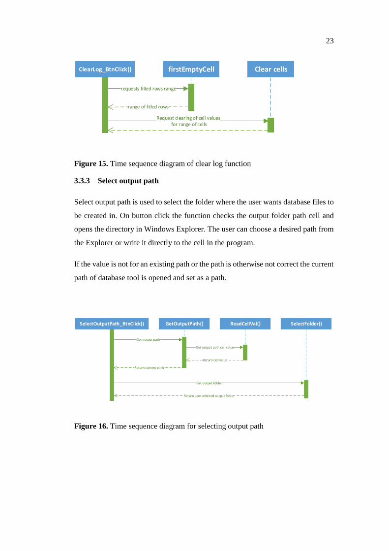
When all of these validations have run, ValidateAll completes and writes RX (Re-
served text) attribute to standard function indexes. After this, the validation is com-
plete and the user gets a validation completion message.
Figure 14. Log of a successful validation
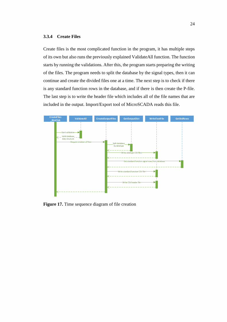
3.3.2 Clear Log
The clear log function, as name implies, clears the tool log and is run when the user
clicks the Clear log –button. The function figures out the area between the main
sheet header and the first empty cell in log area. Then creating a range between
these cells the function gets the range where there are log references and request a
clearing of the cell values.
23
ClearLog_BtnClick() firstEmptyCell Clear cells
requests filled rows range
range of filled rows
Request clearing of cell values for range of cells
Figure 15. Time sequence diagram of clear log function
3.3.3 Select output path
Select output path is used to select the folder where the user wants database files to
be created in. On button click the function checks the output folder path cell and
opens the directory in Windows Explorer. The user can choose a desired path from
the Explorer or write it directly to the cell in the program.
If the value is not for an existing path or the path is otherwise not correct the current
path of database tool is opened and set as a path.
SelectOutputPath_BtnClick() GetOutputPath() ReadCellVal() SelectFolder()
Get output path
Return current path
Get output path cell value
Return cell value
Get output folder
Return user selected output folder
Figure 16. Time sequence diagram for selecting output path
24
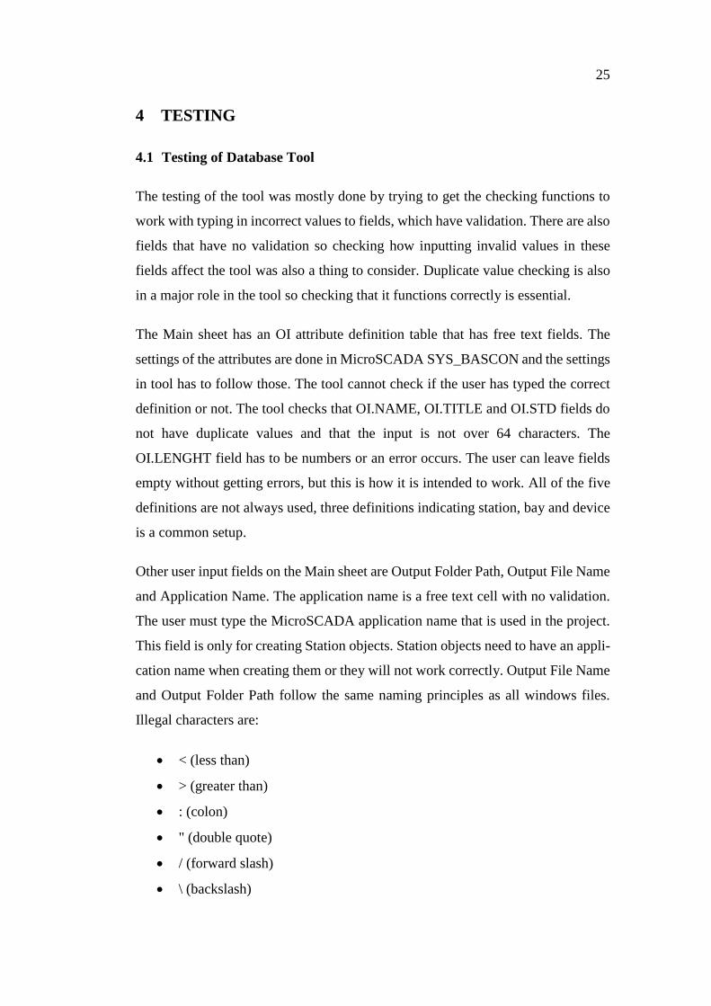
3.3.4 Create Files
Create files is the most complicated function in the program, it has multiple steps
of its own but also runs the previously explained ValidateAll function. The function
starts by running the validations. After this, the program starts preparing the writing
of the files. The program needs to split the database by the signal types, then it can
continue and create the divided files one at a time. The next step is to check if there
is any standard function rows in the database, and if there is then create the P-file.
The last step is to write the header file which includes all of the file names that are
included in the output. Import/Export tool of MicroSCADA reads this file.
CreateFiles_BtnClick
ValidateAll
Start validation
CreateOutputFiles
Request creation of files
Valid database data structure
GetOutputDict
Split database by datatype
WriteTextFile
Write datatype CSV files
GetStdRows
Get standard function signal rows from database
Write standard function CSV file
Write CSV header file
Figure 17. Time sequence diagram of file creation
25
4 TESTING
4.1 Testing of Database Tool
The testing of the tool was mostly done by trying to get the checking functions to
work with typing in incorrect values to fields, which have validation. There are also
fields that have no validation so checking how inputting invalid values in these
fields affect the tool was also a thing to consider. Duplicate value checking is also
in a major role in the tool so checking that it functions correctly is essential.
The Main sheet has an OI attribute definition table that has free text fields. The
settings of the attributes are done in MicroSCADA SYS_BASCON and the settings
in tool has to follow those. The tool cannot check if the user has typed the correct
definition or not. The tool checks that OI.NAME, OI.TITLE and OI.STD fields do
not have duplicate values and that the input is not over 64 characters. The
OI.LENGHT field has to be numbers or an error occurs. The user can leave fields
empty without getting errors, but this is how it is intended to work. All of the five
definitions are not always used, three definitions indicating station, bay and device
is a common setup.
Other user input fields on the Main sheet are Output Folder Path, Output File Name
and Application Name. The application name is a free text cell with no validation.
The user must type the MicroSCADA application name that is used in the project.
This field is only for creating Station objects. Station objects need to have an appli-
cation name when creating them or they will not work correctly. Output File Name
and Output Folder Path follow the same naming principles as all windows files.
Illegal characters are:
< (less than)
> (greater than)
: (colon)
" (double quote)
/ (forward slash)
\ (backslash)
26
| (vertical bar or pipe)
? (question mark)
* (asterisk)
The database sheet has a lot more cells that the user interacts with and many cells
with validation. All of the validation that checks if the type of input is in correct
form, either text or number, is done by the same logic so if one cell of a certain type
works correctly, then all others should also. Additionally, the checking of each Mi-
croSCADA attribute was done with the intent of checking that the values that have
been inserted to DBDefaults as limits are correct. This was done by cross-checking
DBDefaults table with MicroSCADA Application objects manual and making sure
that the code handles the limits and default values correctly.
There are two types of text cells, a number cell type, a Boolean cell type and a
vector cell type. Text can be in a logical name format where it has restrictions with
special characters, use of Nordic characters and space and the character limit. An-
other type is the free text format where it only has character limitation. Errors on
number cell come from typing in anything other than integers and if the number is
bigger or smaller than the limits allow. Boolean needs to be one or zero. Vector
format expects list of comma separated values.
Some of the more important fields that are not easy to see if they are incorrect were
made so that user cannot accidentally make mistakes that are hard to solve. These
fields are filled by the tool based on the other inputs of the user.
The database sheet was also tested with many foreseeable user mistakes, a few of
important ones are listed below. All of these cases are handled and the log message
gives information accordingly.
Typing the same LN IX combination twice
Inserting indexes that are not defined for the standard function type
Adding a column to sheet header
Creating empty rows in between signals
27
Creating and validating the database as a whole was the point where errors were
expected and they were present. Most of the errors that occurred were caused by
missing some information when filling in the default tables. The validations of the
tool worked well and the log made it easy to see where the problems were and the
correcting measures were easy to make. Fields with no validation because it is im-
possible to make without connection to MicroSCADA are an issue that is left to be
handled by counting on that the user is a professional and has the help of the manual
and realizes that it must be checked manually.
4.2 Testing the Interface with MicroSCADA
Testing the interface and the import function of MicroSCADA with the files that
are created with Database Tool was simply done by creating files and trying to im-
port them. The fact that the program is creating files properly does not mean that
the files are completely in a correct format. Some minor issues were present with
the standard function P-file. When importing the files MicroSCADA reads the P-
file as SCIL and the import tool gives errors if there is a slightest error in the syntax.
Most of the errors came from incorrectly filled attribute values in default value ta-
bles.
4.3 Testing the Actual Use of Database Objects in MicroSCADA
The last step is to check if the Display builder graphic objects work correctly and
dialogs open normally. All of the possible Standard functions that the Database tool
can create were made and the database was imported to a virtual machine which
has a MicroSCADA 9.4 installation. The Standard functions that can be created
with the Database tool were cut from original 10 to 7. These were shortlisted out of
the group as useful functions that are still used in new projects. The Standard func-
tions that database tool can create:
Alarm indication
Bay
Line indicator
Measurement
28
Station
Switching device
Tap changer
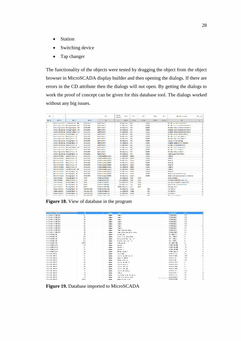
The functionality of the objects were tested by dragging the object from the object
browser in MicroSCADA display builder and then opening the dialogs. If there are
errors in the CD attribute then the dialogs will not open. By getting the dialogs to
work the proof of concept can be given for this database tool. The dialogs worked
without any big issues.
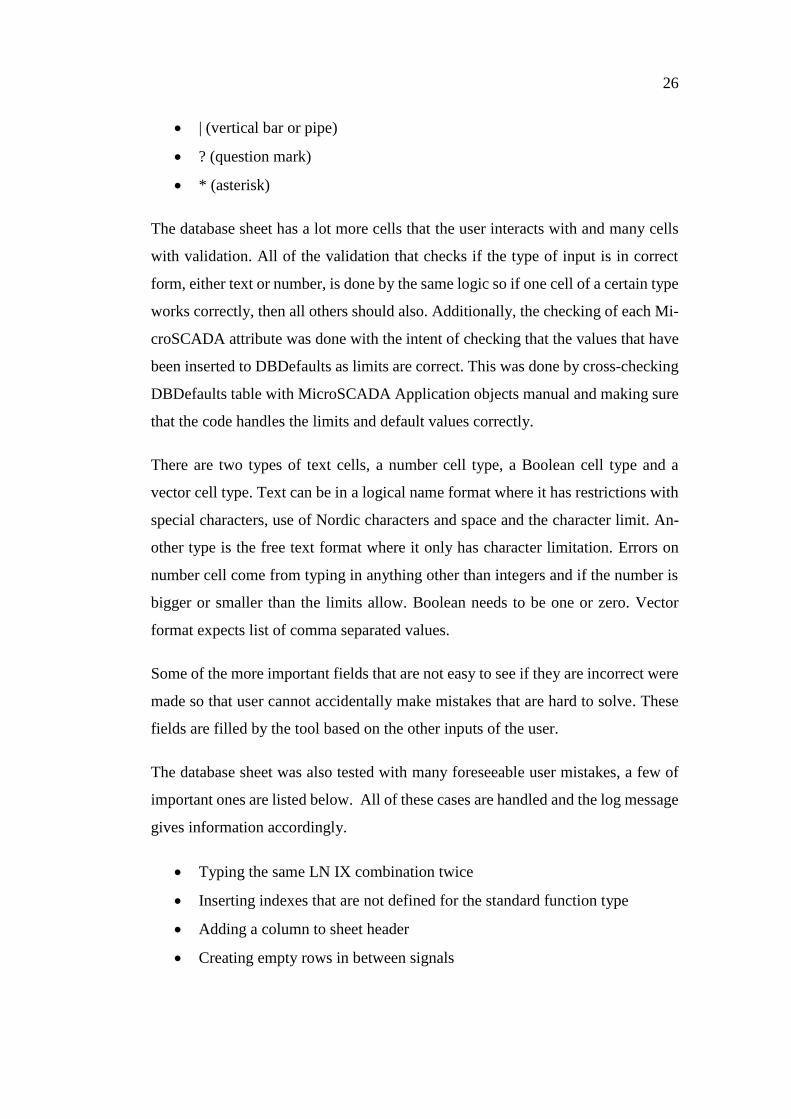
Figure 18. View of database in the program
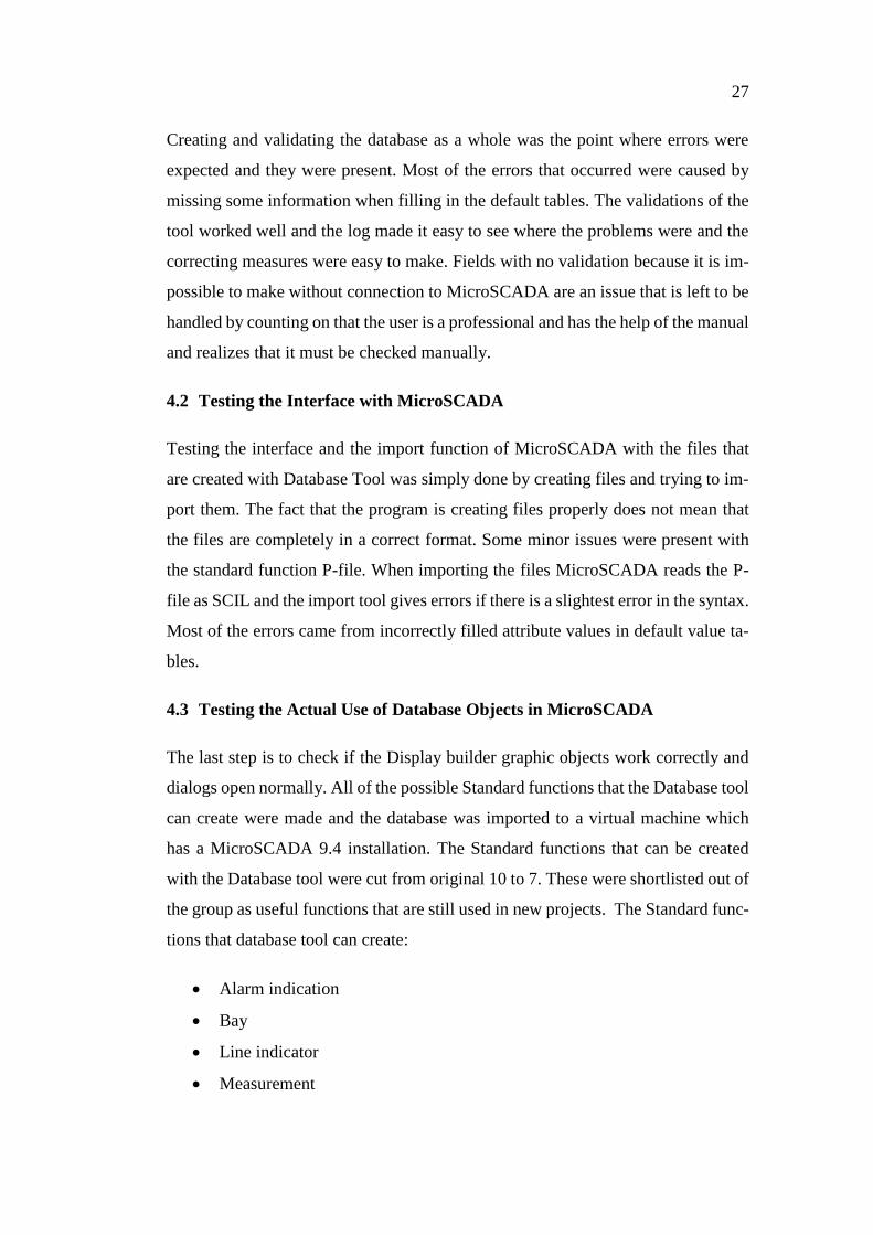
Figure 19. Database imported to MicroSCADA
29
Figure 20. Graphic objects in MicroSCADA monitor pro and a dialog of an alarm
indicator with simulated values
30
5 CONCLUSIONS
The Database tool meets most of the requirements set for the tool. The tool is stable,
has easy to grasp functionalities and error solving that helps the user with infor-
mation that is easy to understand. The tool can create standard functions as well as
basic database objects and it has a wide variety of default values, which helps the
user fill in cells more easily when creating standard functions. If there were a stand-
ard function index that would have been omitted, it is easy to add the definition to
the default tables due to dynamic coding.
The tool is completely independent from MicroSCADA and it works with the ex-
isting import/export tool interface in SCADA.
The only thing that was not included was the reading of export files from Mi-
croSCADA. This functionality had to be left out because of the amount of work
would not have been possible to do in the given time. This would be an obvious
point to continue in the development of this tool.
The tool with the current functionalities is still an improvement to the existing
means when it was tested it in a small scale, although it will be tested properly when
the pilot project will be done with the tool.
31
REFERENCES
/1/ ABB. Accessed 07.05.2018. http://new.abb.com/about
/2/ ABB lyhyesti. Accessed 07.05.2018. http://new.abb.com/fi/abb-lyhyesti/histo-
ria
/3/ ABB Businesses. Accessed 07.05.2018 http://new.abb.com/about/our-busi-
nesses
/4/ ABB suomessa. Accessed 07.05.2018 http://new.abb.com/fi/abb-lyhyesti/su-
omessa
/5/ Grid Automation Systems. Accessed 07.05.2018 http://new.abb.com/fi/abb-
lyhyesti/suomessa/yksikot/grid-automation-systems
/6/ Grid Automation. Accessed 07.05.2018 https://go.insideplus.abb.com/divi-
sions/power-grids/bu-portals/grid-automation
/7/ MicroSCADA Pro for Substation Automation. Product brochure ABB
/8/ MicroSCADA Pro SYS600 Application Design. Product manual ABB