iti data centre iti - tender.itiltd-india.comtender.itiltd-india.com/bgp/tenders/elec ht tech...
TRANSCRIPT
Date :04/12/17Version :00
TECHNICALBIDFORELECTRICALHTWORKFORPROPOSED
ITIDATACENTREAT:ITI,BENGALURU.
CLIENT
ITIAT:BENAGALURU.DATECENTRECONSULTANT
TRIMAXITINFRASTRUCTURE&SERVICESLTDAT:MUMBAI
(Contractor’sStamp&Signatur)s
ITI DATA CENTER @ BENGALURU TRIMAX IT INFRASTRUCTURE
BIDDER’S SIGN & STAMP TECHNICAL SPECIFICATION 2
TECHNICALSPECIFICATIONFORELECTRICALWORK
11KVSWITCHGEAR1 VCB1.1.1 Scope Manufacturing,testingandsupplyingofintegratedcubicletypemetalclad,form3a,floormountedanddrawouttypefreestanding,frontoperatedindoortype11KVswitchgearasperspecificationsgivenbelow: System TheswitchgearenclosureshallconformtodegreeofprotectionIP4X. TheswitchgearshallbemadefromMSsheetsteel2mmthick(CRGO)andshallbefoldedandbracedasnecessarytoprovidearigidsupportforallcomponents. Theswitchgearassemblyshallformacontinuousdeadfrontlineupoffreestandingverticalcubicles.Eachcubicleshallhavealockablefronthingeddoorandaremovableboltedbackcover.Allcoversanddoorsshallbeprovidedwithneoprenegaskets.Suitablearrangementforliftingofeachcubicleshallbeprovided.Designandconstructionoftheswitchgearshallbesuchastopermitextensionateitherend. VacuumCircuitbreakershallbeprovidedwithsurgearrestingdeviceforprotectionagainstlightningandswitchingovervoltage.Twoseparateanddistinctconnectionstoearthshallbeprovidedforeachsurgearrestor.1.1.2 BreakerCompartment VacuumCircuitBreakershallbemountedindrawouttruckwithfrontplatewhichcoversthecubiclewhenthebreakerisinserviceposition.ThisfrontplateshallbeprovidedwithviewglasstofacilitateobservationofmechanicalON/OFFindicationofCircuitbreaker,Springcharged/dischargedindicationandoperationcounter.Necessaryorificeshallbeprovidedformanualchargingofthesprings.ON/OFFpushbuttonforopeningandclosingofthecircuitbreakershallalsobeprovided.ThedrawouttruckshallhavetwopositionsforthecircuitbreakerVIZisolated/Test&Service. 1.1.3 BusBarCompartment Busbarsofrectangularcrosssectionofcopperconductorsupportedbycastepoxyinsulatortowithstandfullshortcircuitcurrentsupto26.3for1sec.for22KVsystemshallbeprovidedattherear.Busbarchambershallbeprovidedwithinterpanelbarrierswithepoxycastsealoffbushings. 1.1.4 CTandCableCompartments AttherearofthepanelsufficientspaceshallbeavailabletoaccommodatethreenumbersepoxyCT’sofdoublecoreandtwonumbersthreecorecabletermination.Thecableentryshallbefromthetop/bottom.
ITI DATA CENTER @ BENGALURU TRIMAX IT INFRASTRUCTURE
BIDDER’S SIGN & STAMP TECHNICAL SPECIFICATION 3
1.1.5 SeparateCompartments Circuitbreakers,instrumenttransformer,busbars,cableetcshallbehousedinadistrictdifferentcompartmentsasrequiredforform3a,compartmentalization.Allrelays,switches,lamps,etc.comprisingthecontrol,indicationandprotectivedevicesshallbehousedinaseparatecompartmentonthefrontofthecubicle.
ITI DATA CENTER @ BENGALURU TRIMAX IT INFRASTRUCTURE
BIDDER’S SIGN & STAMP TECHNICAL SPECIFICATION 4
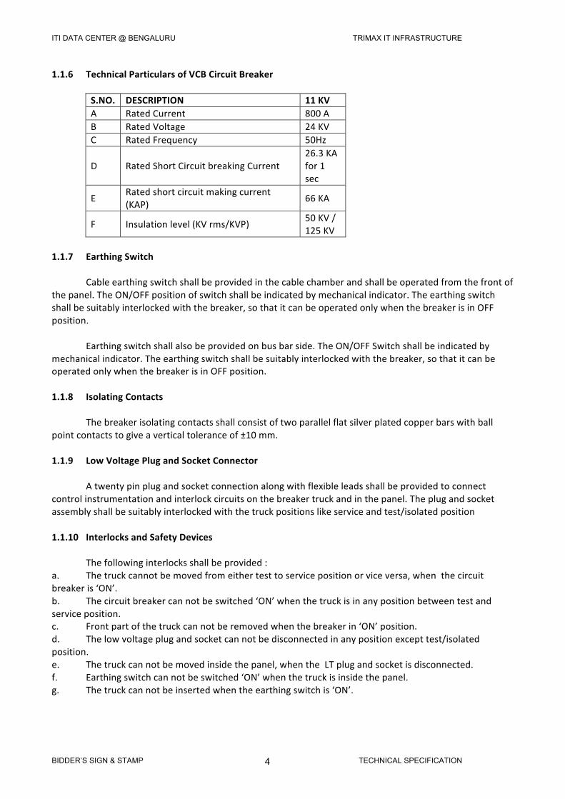
1.1.6 TechnicalParticularsofVCBCircuitBreaker
S.NO. DESCRIPTION 11KVA RatedCurrent 800AB RatedVoltage 24KVC RatedFrequency 50Hz
D RatedShortCircuitbreakingCurrent26.3KAfor1sec
E Ratedshortcircuitmakingcurrent(KAP) 66KA
F Insulationlevel(KVrms/KVP) 50KV/125KV
1.1.7 EarthingSwitch Cableearthingswitchshallbeprovidedinthecablechamberandshallbeoperatedfromthefrontofthepanel.TheON/OFFpositionofswitchshallbeindicatedbymechanicalindicator.Theearthingswitchshallbesuitablyinterlockedwiththebreaker,sothatitcanbeoperatedonlywhenthebreakerisinOFFposition. Earthingswitchshallalsobeprovidedonbusbarside.TheON/OFFSwitchshallbeindicatedbymechanicalindicator.Theearthingswitchshallbesuitablyinterlockedwiththebreaker,sothatitcanbeoperatedonlywhenthebreakerisinOFFposition.1.1.8 IsolatingContacts Thebreakerisolatingcontactsshallconsistoftwoparallelflatsilverplatedcopperbarswithballpointcontactstogiveaverticaltoleranceof±10mm.1.1.9 LowVoltagePlugandSocketConnector Atwentypinplugandsocketconnectionalongwithflexibleleadsshallbeprovidedtoconnectcontrolinstrumentationandinterlockcircuitsonthebreakertruckandinthepanel.Theplugandsocketassemblyshallbesuitablyinterlockedwiththetruckpositionslikeserviceandtest/isolatedposition1.1.10 InterlocksandSafetyDevices Thefollowinginterlocksshallbeprovided:a. Thetruckcannotbemovedfromeithertesttoservicepositionorviceversa,whenthecircuitbreakeris‘ON’.b. Thecircuitbreakercannotbeswitched‘ON’whenthetruckisinanypositionbetweentestandserviceposition.c. Frontpartofthetruckcannotberemovedwhenthebreakerin‘ON’position.d. Thelowvoltageplugandsocketcannotbedisconnectedinanypositionexcepttest/isolatedposition.e. Thetruckcannotbemovedinsidethepanel,whentheLTplugandsocketisdisconnected.f. Earthingswitchcannotbeswitched‘ON’whenthetruckisinsidethepanel. g. Thetruckcannotbeinsertedwhentheearthingswitchis‘ON’.
ITI DATA CENTER @ BENGALURU TRIMAX IT INFRASTRUCTURE
BIDDER’S SIGN & STAMP TECHNICAL SPECIFICATION 5
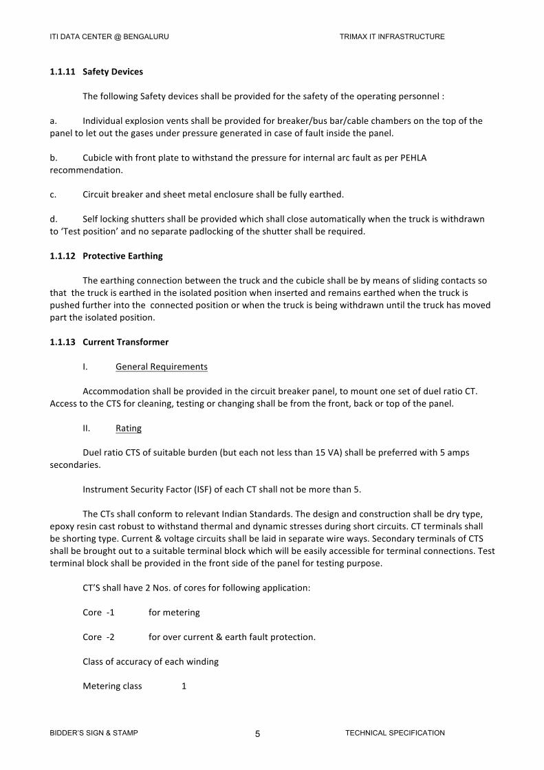
1.1.11 SafetyDevices ThefollowingSafetydevicesshallbeprovidedforthesafetyoftheoperatingpersonnel:a. Individualexplosionventsshallbeprovidedforbreaker/busbar/cablechambersonthetopofthepaneltoletoutthegasesunderpressuregeneratedincaseoffaultinsidethepanel.b. CubiclewithfrontplatetowithstandthepressureforinternalarcfaultasperPEHLArecommendation.c. Circuitbreakerandsheetmetalenclosureshallbefullyearthed.d. Selflockingshuttersshallbeprovidedwhichshallcloseautomaticallywhenthetruckiswithdrawnto‘Testposition’andnoseparatepadlockingoftheshuttershallberequired.1.1.12 ProtectiveEarthing Theearthingconnectionbetweenthetruckandthecubicleshallbebymeansofslidingcontactssothatthetruckisearthedintheisolatedpositionwheninsertedandremainsearthedwhenthetruckispushedfurtherintotheconnectedpositionorwhenthetruckisbeingwithdrawnuntilthetruckhasmovedparttheisolatedposition.1.1.13 CurrentTransformer I. GeneralRequirements Accommodationshallbeprovidedinthecircuitbreakerpanel,tomountonesetofduelratioCT.AccesstotheCTSforcleaning,testingorchangingshallbefromthefront,backortopofthepanel. II. Rating DuelratioCTSofsuitableburden(buteachnotlessthan15VA)shallbepreferredwith5ampssecondaries. InstrumentSecurityFactor(ISF)ofeachCTshallnotbemorethan5. TheCTsshallconformtorelevantIndianStandards.Thedesignandconstructionshallbedrytype,epoxyresincastrobusttowithstandthermalanddynamicstressesduringshortcircuits.CTterminalsshallbeshortingtype.Current&voltagecircuitsshallbelaidinseparatewireways.SecondaryterminalsofCTSshallbebroughtouttoasuitableterminalblockwhichwillbeeasilyaccessibleforterminalconnections.Testterminalblockshallbeprovidedinthefrontsideofthepanelfortestingpurpose. CT’Sshallhave2Nos.ofcoresforfollowingapplication: Core-1 formetering Core-2 forovercurrent&earthfaultprotection. Classofaccuracyofeachwinding Meteringclass 1
ITI DATA CENTER @ BENGALURU TRIMAX IT INFRASTRUCTURE
BIDDER’S SIGN & STAMP TECHNICAL SPECIFICATION 6
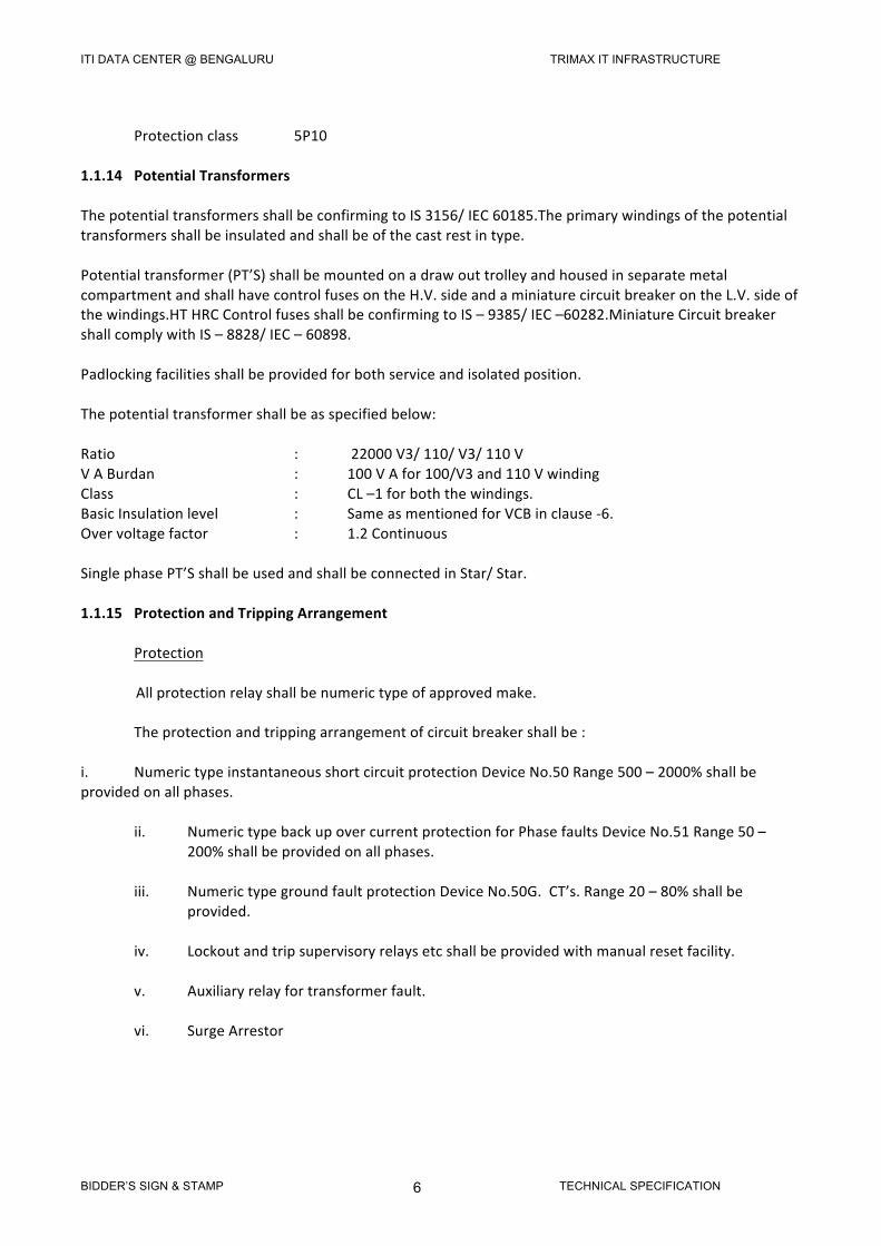
Protectionclass 5P101.1.14 PotentialTransformersThepotentialtransformersshallbeconfirmingtoIS3156/IEC60185.Theprimarywindingsofthepotentialtransformersshallbeinsulatedandshallbeofthecastrestintype.Potentialtransformer(PT’S)shallbemountedonadrawouttrolleyandhousedinseparatemetalcompartmentandshallhavecontrolfusesontheH.V.sideandaminiaturecircuitbreakerontheL.V.sideofthewindings.HTHRCControlfusesshallbeconfirmingtoIS–9385/IEC–60282.MiniatureCircuitbreakershallcomplywithIS–8828/IEC–60898.Padlockingfacilitiesshallbeprovidedforbothserviceandisolatedposition.Thepotentialtransformershallbeasspecifiedbelow:Ratio : 22000V3/110/V3/110VVABurdan : 100VAfor100/V3and110VwindingClass : CL–1forboththewindings.BasicInsulationlevel : SameasmentionedforVCBinclause-6.Overvoltagefactor : 1.2ContinuousSinglephasePT’SshallbeusedandshallbeconnectedinStar/Star.1.1.15 ProtectionandTrippingArrangement ProtectionAllprotectionrelayshallbenumerictypeofapprovedmake. Theprotectionandtrippingarrangementofcircuitbreakershallbe:i. NumerictypeinstantaneousshortcircuitprotectionDeviceNo.50Range500–2000%shallbeprovidedonallphases.
ii. NumerictypebackupovercurrentprotectionforPhasefaultsDeviceNo.51Range50–200%shallbeprovidedonallphases.
iii. NumerictypegroundfaultprotectionDeviceNo.50G.CT’s.Range20–80%shallbe
provided.
iv. Lockoutandtripsupervisoryrelaysetcshallbeprovidedwithmanualresetfacility.
v. Auxiliaryrelayfortransformerfault.
vi. SurgeArrestor
ITI DATA CENTER @ BENGALURU TRIMAX IT INFRASTRUCTURE
BIDDER’S SIGN & STAMP TECHNICAL SPECIFICATION 7
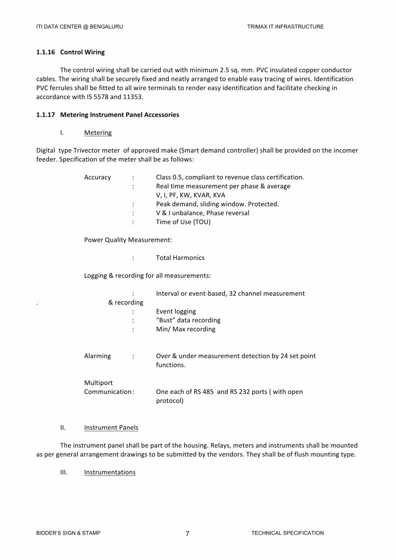
1.1.16 ControlWiring Thecontrolwiringshallbecarriedoutwithminimum2.5sq.mm.PVCinsulatedcopperconductorcables.Thewiringshallbesecurelyfixedandneatlyarrangedtoenableeasytracingofwires.IdentificationPVCferrulesshallbefittedtoallwireterminalstorendereasyidentificationandfacilitatecheckinginaccordancewithIS5578and11353.1.1.17 MeteringInstrumentPanelAccessories I. MeteringDigitaltypeTrivectormeterofapprovedmake(Smartdemandcontroller)shallbeprovidedontheincomerfeeder.Specificationofthemetershallbeasfollows: Accuracy : Class0.5,complianttorevenueclasscertification. : Realtimemeasurementperphase&average V,I,PF,KW,KVAR,KVA : Peakdemand,slidingwindow.Protected. : V&Iunbalance,Phasereversal : TimeofUse(TOU) PowerQualityMeasurement: : TotalHarmonics Logging&recordingforallmeasurements: : Intervalorevent-based,32channelmeasurement. &recording : Eventlogging : “Bust”datarecording : Min/Maxrecording Alarming : Over&undermeasurementdetectionby24setpoint functions. Multiport Communication: OneeachofRS485andRS232ports(withopen protocol) II. InstrumentPanels Theinstrumentpanelshallbepartofthehousing.Relays,metersandinstrumentsshallbemountedaspergeneralarrangementdrawingstobesubmittedbythevendors.Theyshallbeofflushmountingtype. III. Instrumentations
ITI DATA CENTER @ BENGALURU TRIMAX IT INFRASTRUCTURE
BIDDER’S SIGN & STAMP TECHNICAL SPECIFICATION 8
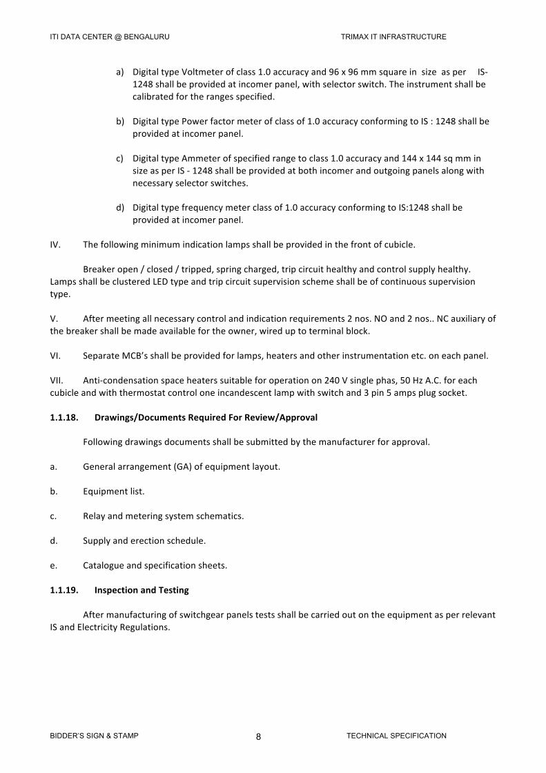
a) DigitaltypeVoltmeterofclass1.0accuracyand96x96mmsquareinsizeasperIS-1248shallbeprovidedatincomerpanel,withselectorswitch.Theinstrumentshallbecalibratedfortherangesspecified.
b) DigitaltypePowerfactormeterofclassof1.0accuracyconformingtoIS:1248shallbe
providedatincomerpanel.
c) DigitaltypeAmmeterofspecifiedrangetoclass1.0accuracyand144x144sqmminsizeasperIS-1248shallbeprovidedatbothincomerandoutgoingpanelsalongwithnecessaryselectorswitches.
d) Digitaltypefrequencymeterclassof1.0accuracyconformingtoIS:1248shallbe
providedatincomerpanel.IV. Thefollowingminimumindicationlampsshallbeprovidedinthefrontofcubicle. Breakeropen/closed/tripped,springcharged,tripcircuithealthyandcontrolsupplyhealthy.LampsshallbeclusteredLEDtypeandtripcircuitsupervisionschemeshallbeofcontinuoussupervisiontype.V. Aftermeetingallnecessarycontrolandindicationrequirements2nos.NOand2nos..NCauxiliaryofthebreakershallbemadeavailablefortheowner,wireduptoterminalblock.VI. SeparateMCB’sshallbeprovidedforlamps,heatersandotherinstrumentationetc.oneachpanel.VII. Anti-condensationspaceheaterssuitableforoperationon240Vsinglephas,50HzA.C.foreachcubicleandwiththermostatcontroloneincandescentlampwithswitchand3pin5ampsplugsocket.1.1.18.Drawings/DocumentsRequiredForReview/Approval Followingdrawingsdocumentsshallbesubmittedbythemanufacturerforapproval.a. Generalarrangement(GA)ofequipmentlayout.b. Equipmentlist.c. Relayandmeteringsystemschematics.d. Supplyanderectionschedule.e. Catalogueandspecificationsheets.1.1.19.InspectionandTesting AftermanufacturingofswitchgearpanelstestsshallbecarriedoutontheequipmentasperrelevantISandElectricityRegulations.
ITI DATA CENTER @ BENGALURU TRIMAX IT INFRASTRUCTURE
BIDDER’S SIGN & STAMP TECHNICAL SPECIFICATION 9
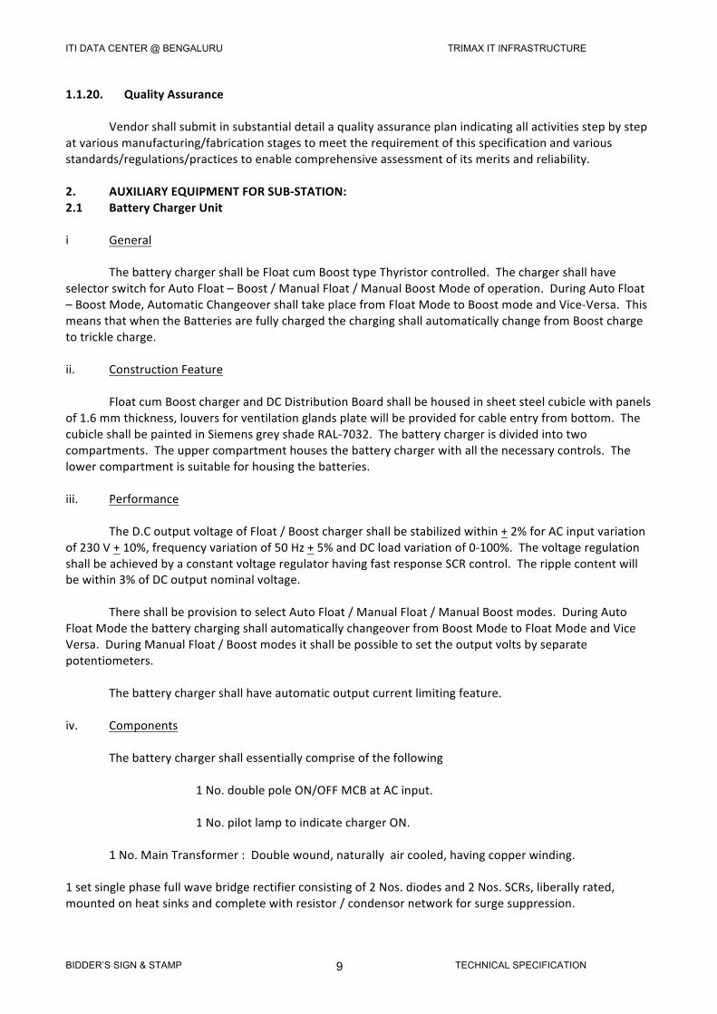
1.1.20.QualityAssurance Vendorshallsubmitinsubstantialdetailaqualityassuranceplanindicatingallactivitiesstepbystepatvariousmanufacturing/fabricationstagestomeettherequirementofthisspecificationandvariousstandards/regulations/practicestoenablecomprehensiveassessmentofitsmeritsandreliability.2. AUXILIARYEQUIPMENTFORSUB-STATION:2.1 BatteryChargerUniti General ThebatterychargershallbeFloatcumBoosttypeThyristorcontrolled.ThechargershallhaveselectorswitchforAutoFloat–Boost/ManualFloat/ManualBoostModeofoperation.DuringAutoFloat–BoostMode,AutomaticChangeovershalltakeplacefromFloatModetoBoostmodeandVice-Versa.ThismeansthatwhentheBatteriesarefullychargedthechargingshallautomaticallychangefromBoostchargetotricklecharge.ii. ConstructionFeature FloatcumBoostchargerandDCDistributionBoardshallbehousedinsheetsteelcubiclewithpanelsof1.6mmthickness,louversforventilationglandsplatewillbeprovidedforcableentryfrombottom.ThecubicleshallbepaintedinSiemensgreyshadeRAL-7032.Thebatterychargerisdividedintotwocompartments.Theuppercompartmenthousesthebatterychargerwithallthenecessarycontrols.Thelowercompartmentissuitableforhousingthebatteries.iii. Performance TheD.CoutputvoltageofFloat/Boostchargershallbestabilizedwithin+2%forACinputvariationof230V+10%,frequencyvariationof50Hz+5%andDCloadvariationof0-100%.ThevoltageregulationshallbeachievedbyaconstantvoltageregulatorhavingfastresponseSCRcontrol.Theripplecontentwillbewithin3%ofDCoutputnominalvoltage. ThereshallbeprovisiontoselectAutoFloat/ManualFloat/ManualBoostmodes.DuringAutoFloatModethebatterychargingshallautomaticallychangeoverfromBoostModetoFloatModeandViceVersa.DuringManualFloat/Boostmodesitshallbepossibletosettheoutputvoltsbyseparatepotentiometers. Thebatterychargershallhaveautomaticoutputcurrentlimitingfeature.iv. Components Thebatterychargershallessentiallycompriseofthefollowing 1No.doublepoleON/OFFMCBatACinput. 1No.pilotlamptoindicatechargerON. 1No.MainTransformer:Doublewound,naturallyaircooled,havingcopperwinding.1setsinglephasefullwavebridgerectifierconsistingof2Nos.diodesand2Nos.SCRs,liberallyrated,mountedonheatsinksandcompletewithresistor/condensornetworkforsurgesuppression.
ITI DATA CENTER @ BENGALURU TRIMAX IT INFRASTRUCTURE
BIDDER’S SIGN & STAMP TECHNICAL SPECIFICATION 10
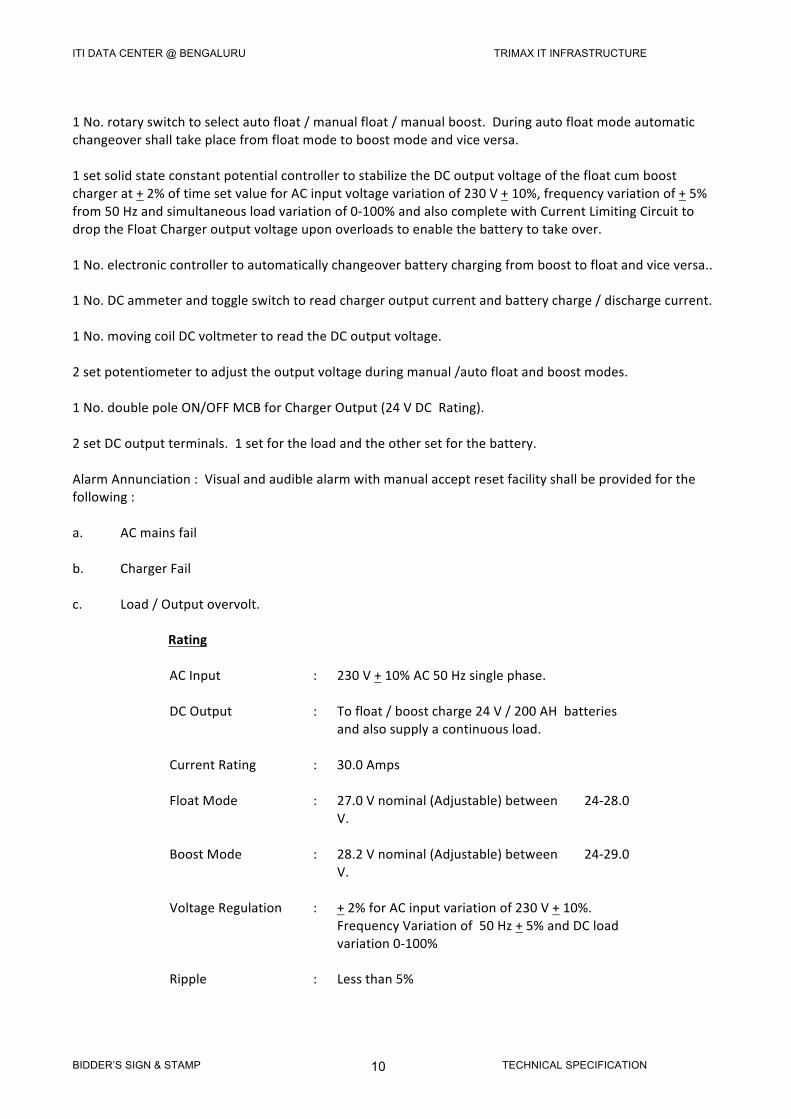
1No.rotaryswitchtoselectautofloat/manualfloat/manualboost.Duringautofloatmodeautomaticchangeovershalltakeplacefromfloatmodetoboostmodeandviceversa.1setsolidstateconstantpotentialcontrollertostabilizetheDCoutputvoltageofthefloatcumboostchargerat+2%oftimesetvalueforACinputvoltagevariationof230V+10%,frequencyvariationof+5%from50Hzandsimultaneousloadvariationof0-100%andalsocompletewithCurrentLimitingCircuittodroptheFloatChargeroutputvoltageuponoverloadstoenablethebatterytotakeover.1No.electroniccontrollertoautomaticallychangeoverbatterychargingfromboosttofloatandviceversa..1No.DCammeterandtoggleswitchtoreadchargeroutputcurrentandbatterycharge/dischargecurrent.1No.movingcoilDCvoltmetertoreadtheDCoutputvoltage.2setpotentiometertoadjusttheoutputvoltageduringmanual/autofloatandboostmodes.1No.doublepoleON/OFFMCBforChargerOutput(24VDCRating).2setDCoutputterminals.1setfortheloadandtheothersetforthebattery.AlarmAnnunciation:Visualandaudiblealarmwithmanualacceptresetfacilityshallbeprovidedforthefollowing:a. ACmainsfailb. ChargerFailc. Load/Outputovervolt. Rating
ACInput : 230V+10%AC50Hzsinglephase.
DCOutput : Tofloat/boostcharge24V/200AHbatteriesandalsosupplyacontinuousload.
CurrentRating : 30.0Amps
FloatMode : 27.0Vnominal(Adjustable)between24-28.0V.
BoostMode : 28.2Vnominal(Adjustable)between24-29.0V.
VoltageRegulation : +2%forACinputvariationof230V+10%.FrequencyVariationof50Hz+5%andDCloadvariation0-100%
Ripple : Lessthan5%
ITI DATA CENTER @ BENGALURU TRIMAX IT INFRASTRUCTURE
BIDDER’S SIGN & STAMP TECHNICAL SPECIFICATION 11
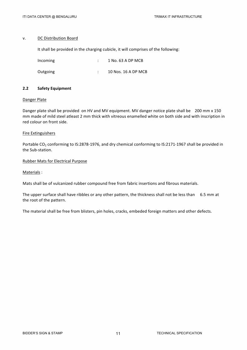
v. DCDistributionBoard Itshallbeprovidedinthechargingcubicle,itwillcomprisesofthefollowing: Incoming :1No.63ADPMCB Outgoing :10Nos.16ADPMCB2.2 SafetyEquipmentDangerPlateDangerplateshallbeprovidedonHVandMVequipment.MVdangernoticeplateshallbe200mmx150mmmadeofmildsteelatleast2mmthickwithvitreousenamelledwhiteonbothsideandwithinscriptioninredcolouronfrontside.FireExtinguishersPortableCO2conformingtoIS:2878-1976,anddrychemicalconformingtoIS:2171-1967shallbeprovidedintheSub-station.RubberMatsforElectricalPurposeMaterials:Matsshallbeofvulcanizedrubbercompoundfreefromfabricinsertionsandfibrousmaterials.Theuppersurfaceshallhaveribblesoranyotherpattern,thethicknessshallnotbelessthan6.5mmattherootofthepattern.Thematerialshallbefreefromblisters,pinholes,cracks,embededforeignmattersandotherdefects.
ITI DATA CENTER @ BENGALURU TRIMAX IT INFRASTRUCTURE
BIDDER’S SIGN & STAMP TECHNICAL SPECIFICATION 12
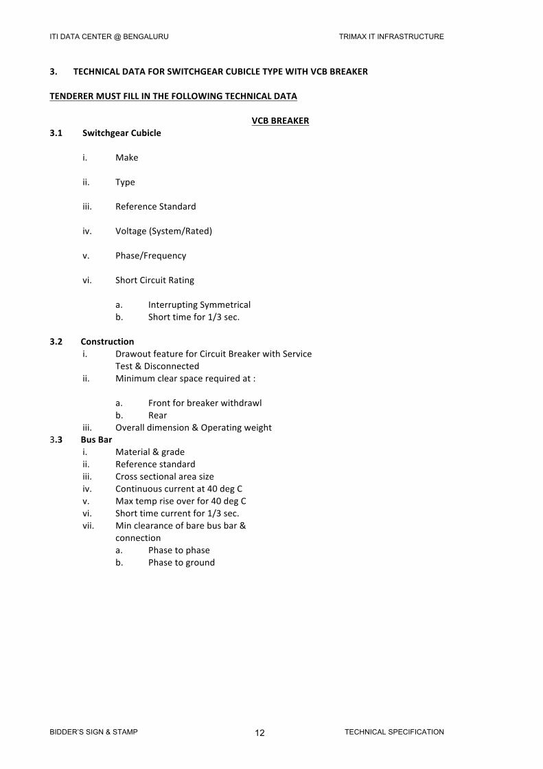
3.TECHNICALDATAFORSWITCHGEARCUBICLETYPEWITHVCBBREAKERTENDERERMUSTFILLINTHEFOLLOWINGTECHNICALDATA VCBBREAKER 3.1 SwitchgearCubicle i. Make ii. Type iii. ReferenceStandard iv. Voltage(System/Rated) v. Phase/Frequency vi. ShortCircuitRating a. InterruptingSymmetrical b. Shorttimefor1/3sec.3.2Construction i. DrawoutfeatureforCircuitBreakerwithService Test&Disconnected ii. Minimumclearspacerequiredat: a. Frontforbreakerwithdrawl b. Rear iii. Overalldimension&Operatingweight3.3BusBar i. Material&grade ii. Referencestandard iii. Crosssectionalareasize iv. Continuouscurrentat40degC v. Maxtempriseoverfor40degC vi. Shorttimecurrentfor1/3sec. vii. Minclearanceofbarebusbar& connection a. Phasetophase b. Phasetoground

ITI DATA CENTER @ BENGALURU TRIMAX IT INFRASTRUCTURE
BIDDER’S SIGN & STAMP TECHNICAL SPECIFICATION 13
VCBBREAKER 3.4CircuitBreaker i. Make ii. Type iii. Ratedvoltage iv. Ratedfrequency v. No.ofpoles vi. Ratedcurrent a. Continuousat40degC&within cubicle b. Shorttimecurrentfor1sec/3sec3.5 Max.tempriseover40degCambient3.6Ratedoperatingduty3.7Interruptingcapacityatratedvoltage andoperatingduty a. Symmetrical3.8Ratedmakingcurrent3.9 No.ofbreakeroperationspermissible withoutrequiringinspectionforrefilling SF6gasreplacementofcontacts&other NotApplicable mainparts. a. At100%ratedcurrent b. At100%ratedshortcircuitcurrent3.10Typeofcontacts a. Main b. Arcing3.11Minclearanceinair a. Betweenpoles b. Betweenliveparts&ground3.12Operatingmechanism a. Type
ITI DATA CENTER @ BENGALURU TRIMAX IT INFRASTRUCTURE
BIDDER’S SIGN & STAMP TECHNICAL SPECIFICATION 14
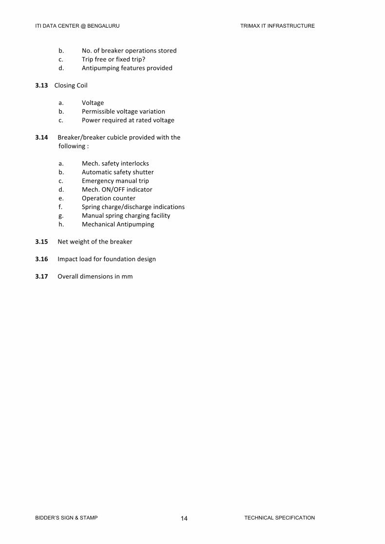
b. No.ofbreakeroperationsstored c. Tripfreeorfixedtrip? d. Antipumpingfeaturesprovided3.13ClosingCoil a. Voltage b. Permissiblevoltagevariation c. Powerrequiredatratedvoltage3.14Breaker/breakercubicleprovidedwiththe following: a. Mech.safetyinterlocks b. Automaticsafetyshutter c. Emergencymanualtrip d. Mech.ON/OFFindicator e. Operationcounter f. Springcharge/dischargeindications g. Manualspringchargingfacility h. MechanicalAntipumping3.15Netweightofthebreaker3.16Impactloadforfoundationdesign3.17Overalldimensionsinmm
ITI DATA CENTER @ BENGALURU TRIMAX IT INFRASTRUCTURE
BIDDER’S SIGN & STAMP TECHNICAL SPECIFICATION 15
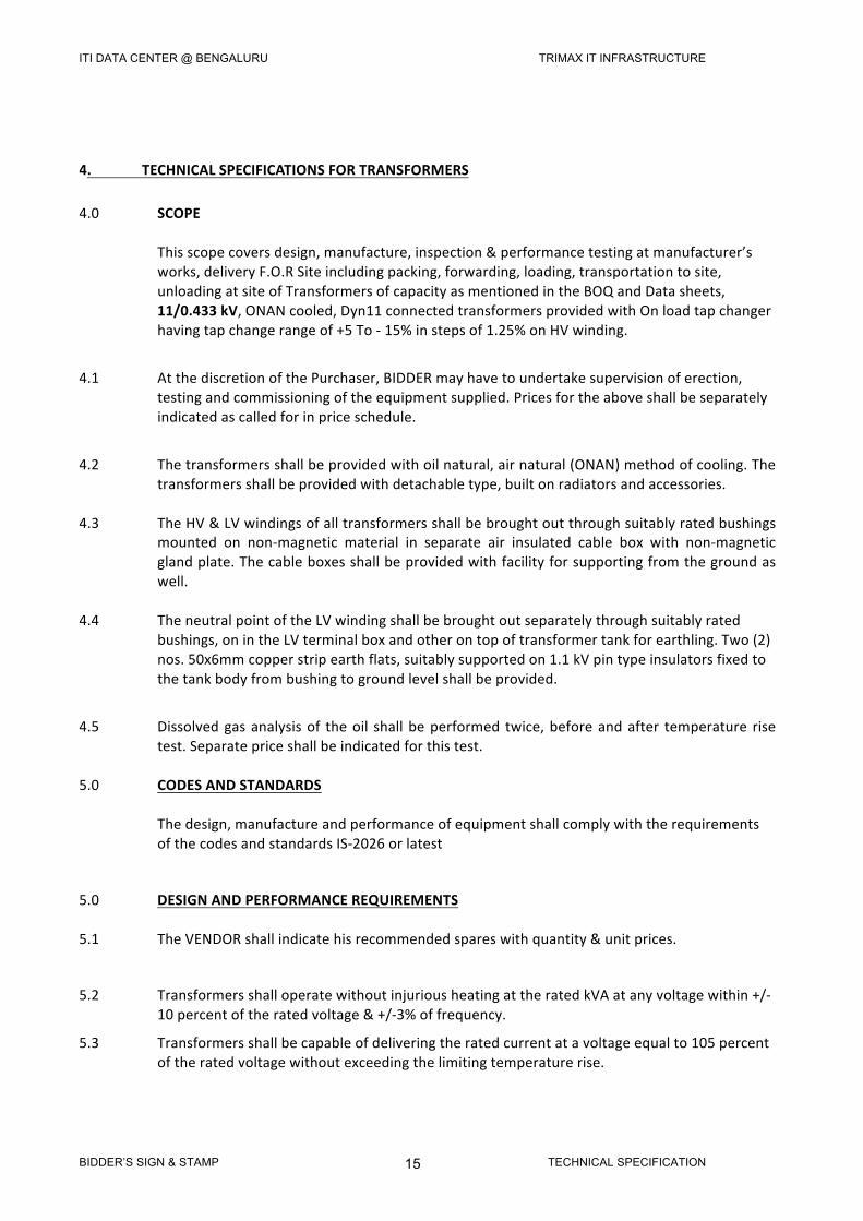
4.TECHNICALSPECIFICATIONSFORTRANSFORMERS
4.0 SCOPE Thisscopecoversdesign,manufacture,inspection&performancetestingatmanufacturer’s
works,deliveryF.O.RSiteincludingpacking,forwarding,loading,transportationtosite,unloadingatsiteofTransformersofcapacityasmentionedintheBOQandDatasheets,11/0.433kV,ONANcooled,Dyn11connectedtransformersprovidedwithOnloadtapchangerhavingtapchangerangeof+5To-15%instepsof1.25%onHVwinding.
4.1 AtthediscretionofthePurchaser,BIDDERmayhavetoundertakesupervisionoferection,
testingandcommissioningoftheequipmentsupplied.Pricesfortheaboveshallbeseparatelyindicatedascalledforinpriceschedule.
4.2 Thetransformersshallbeprovidedwithoilnatural,airnatural(ONAN)methodofcooling.The
transformersshallbeprovidedwithdetachabletype,builtonradiatorsandaccessories.4.3 TheHV&LVwindingsofalltransformersshallbebroughtoutthroughsuitablyratedbushings
mounted on non-magnetic material in separate air insulated cable box with non-magneticglandplate.Thecableboxesshallbeprovidedwithfacilityforsupportingfromthegroundaswell.
4.4 TheneutralpointoftheLVwindingshallbebroughtoutseparatelythroughsuitablyrated
bushings,onintheLVterminalboxandotherontopoftransformertankforearthling.Two(2)nos.50x6mmcopperstripearthflats,suitablysupportedon1.1kVpintypeinsulatorsfixedtothetankbodyfrombushingtogroundlevelshallbeprovided.
4.5 Dissolvedgasanalysisof theoil shallbeperformed twice,beforeandafter temperature rise
test.Separatepriceshallbeindicatedforthistest.5.0 CODESANDSTANDARDS Thedesign,manufactureandperformanceofequipmentshallcomplywiththerequirements
ofthecodesandstandardsIS-2026orlatest
5.0 DESIGNANDPERFORMANCEREQUIREMENTS5.1 TheVENDORshallindicatehisrecommendedspareswithquantity&unitprices.
5.2 TransformersshalloperatewithoutinjuriousheatingattheratedkVAatanyvoltagewithin+/-10percentoftheratedvoltage&+/-3%offrequency.
5.3 Transformersshallbecapableofdeliveringtheratedcurrentatavoltageequalto105percentoftheratedvoltagewithoutexceedingthelimitingtemperaturerise.
ITI DATA CENTER @ BENGALURU TRIMAX IT INFRASTRUCTURE
BIDDER’S SIGN & STAMP TECHNICAL SPECIFICATION 16
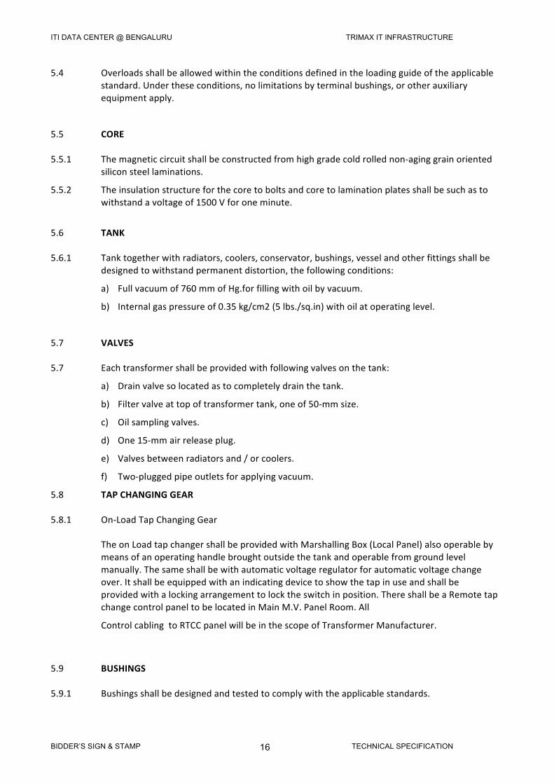
5.4 Overloadsshallbeallowedwithintheconditionsdefinedintheloadingguideoftheapplicablestandard.Undertheseconditions,nolimitationsbyterminalbushings,orotherauxiliaryequipmentapply.
5.5 CORE5.5.1 Themagneticcircuitshallbeconstructedfromhighgradecoldrollednon-aginggrainoriented
siliconsteellaminations.
5.5.2 Theinsulationstructureforthecoretoboltsandcoretolaminationplatesshallbesuchastowithstandavoltageof1500Vforoneminute.
5.6 TANK5.6.1 Tanktogetherwithradiators,coolers,conservator,bushings,vesselandotherfittingsshallbe
designedtowithstandpermanentdistortion,thefollowingconditions:
a) Fullvacuumof760mmofHg.forfillingwithoilbyvacuum.
b) Internalgaspressureof0.35kg/cm2(5lbs./sq.in)withoilatoperatinglevel.
5.7 VALVES5.7 Eachtransformershallbeprovidedwithfollowingvalvesonthetank:
a) Drainvalvesolocatedastocompletelydrainthetank.
b) Filtervalveattopoftransformertank,oneof50-mmsize.
c) Oilsamplingvalves.
d) One15-mmairreleaseplug.
e) Valvesbetweenradiatorsand/orcoolers.
f) Two-pluggedpipeoutletsforapplyingvacuum.
5.8 TAPCHANGINGGEAR5.8.1 On-LoadTapChangingGear TheonLoadtapchangershallbeprovidedwithMarshallingBox(LocalPanel)alsooperableby
meansofanoperatinghandlebroughtoutsidethetankandoperablefromgroundlevelmanually.Thesameshallbewithautomaticvoltageregulatorforautomaticvoltagechangeover.Itshallbeequippedwithanindicatingdevicetoshowthetapinuseandshallbeprovidedwithalockingarrangementtolocktheswitchinposition.ThereshallbeaRemotetapchangecontrolpaneltobelocatedinMainM.V.PanelRoom.All
ControlcablingtoRTCCpanelwillbeinthescopeofTransformerManufacturer.
5.9 BUSHINGS5.9.1 Bushingsshallbedesignedandtestedtocomplywiththeapplicablestandards.
ITI DATA CENTER @ BENGALURU TRIMAX IT INFRASTRUCTURE
BIDDER’S SIGN & STAMP TECHNICAL SPECIFICATION 17
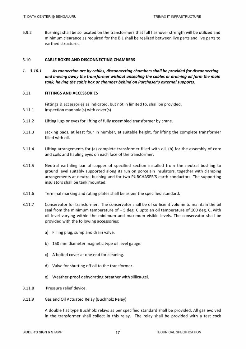
5.9.2 BushingsshallbesolocatedonthetransformersthatfullflashoverstrengthwillbeutilizedandminimumclearanceasrequiredfortheBILshallberealizedbetweenlivepartsandlivepartstoearthedstructures.
5.10 CABLEBOXESANDDISCONNECTINGCHAMBERS1. 3.10.1 Asconnectionarebycables,disconnectingchambersshallbeprovidedfordisconnecting
andmovingawaythetransformerwithoutunsealingthecablesordrainingoilformthemaintank,havingthecableboxorchamberbehindonPurchaser’sexternalsupports.
3.11 FITTINGSANDACCESSORIES Fittings&accessoriesasindicated,butnotinlimitedto,shallbeprovided.3.11.1 Inspectionmanhole(s)withcover(s).3.11.2 Liftinglugsoreyesforliftingoffullyassembledtransformerbycrane.3.11.3 Jackingpads,at least four innumber,at suitableheight, for lifting thecomplete transformer
filledwithoil.3.11.4 Liftingarrangements for (a)completetransformerfilledwithoil, (b) fortheassemblyofcore
andcoilsandhaulingeyesoneachfaceofthetransformer.3.11.5 Neutral earthling bar of copper of specified section installed from the neutral bushing to
ground level suitablysupportedalong its runonporcelain insulators, togetherwithclampingarrangementsatneutralbushingandfortwoPURCHASER’Searthconductors.Thesupportinginsulatorsshallbetankmounted.
3.11.6 Terminalmarkingandratingplatesshallbeasperthespecifiedstandard.3.11.7 Conservatorfortransformer.Theconservatorshallbeofsufficientvolumetomaintaintheoil
sealfromtheminimumtemperatureof–5deg.Cuptoanoiltemperatureof100deg.C,withoil level varying within the minimum and maximum visible levels. The conservator shall beprovidedwiththefollowingaccessories:
a) Fillingplug,sumpanddrainvalve. b) 150mmdiametermagnetictypeoillevelgauge. c) Aboltedcoveratoneendforcleaning.
d) Valveforshuttingoffoiltothetransformer.
e) Weather-proofdehydratingbreatherwithsillica-gel. 3.11.8 Pressurereliefdevice.3.11.9 GasandOilActuatedRelay(BuchholzRelay) AdoubleflattypeBuchholzrelaysasperspecifiedstandardshallbeprovided.Allgasevolved
in the transformer shall collect in this relay. The relay shall be provided with a test cock
ITI DATA CENTER @ BENGALURU TRIMAX IT INFRASTRUCTURE
BIDDER’S SIGN & STAMP TECHNICAL SPECIFICATION 18
suitableforaflexiblepipeconnectionforcheckingitsoperation.A5mmcopperpipeshallbeconnected from the relay test cock to a valve located about 1.25M above ground level tofacilitate sampling with the transformer in service. The device with two electricallyindependent ungrounded contacts, one for alarm on gas accumulation and the other fortripping on sudden rise of pressure. These contacts shall be wired upto transformermarshallingbox.Therelayshallbeprovidedwithshut-offvalvesonconservatorsideaswellasthetankside.
3.11.10 TemperatureIndicators3.11.11 DialTypeThermometer All transformers shall be provided with dial type thermometer for top oil temperature
indication.Thethermometershallhaveadjustableelectricallyindependentungroundedalarmandtripcontacts,maximumreadingpointerandresettingdevice.Thecontactsshallberatedminimum0.5Amakingand0.2Abreakingat220VD.C.
3.11.12 Asetofhydraulicjackssuitableforthetransformerundersupply.3.12 TESTS AlltransformersshallbecompletelyassembledatWorkstoascertainthatallpartsfitcorrectly.3.12.1 RoutineTests Routinetestsasperspecifiedstandardsshallbeperformedonalltransformers.Thefollowing
additionalpointsmaybenoted. a) Resistanceofeachwindingofeachphaseshallbemeasuredat principal and at all the
tapsandcorrectedto75deg.C. b) Impedancevoltageshallbemeasuredatprincipalandatallthetaps. c) Noloadlossandexistingcurrentshallbemeasuredatrated frequency at 90%, 100%
and330%ratedvoltage.Thesetests shall be done after impulse tests if the latter arespecified. Excitingcurrentshallbemeasuredoneachphaserecorded.Form factorshallbenotedduringthetestandincludedinthetestreport.
d) Noloadlossandexcitingcurrentshallbemeasuredandrecorded with 415V, 3
phase,50Hz.inputonLVside(assumingLVis ratedhigherthan415V). e) OilLeakageTest:Themaintransformertankandalloilfilledcompartmentsnecessaryfora
completetransformerincluding coolersshallbefilledwithtransformeroilandsubjectedtoa pressure of 0.35 Kg/cm2, above the pressure that would be obtained under normalconditionswith full headof oil. Thepressure shall bemaintained for 12hours duringwhichtimeno oilleakageshalloccur.Whenheatruntestisspecified,theoil pressure test shallbeperformedimmediatelyafterheatrun. Otherwise the testmaybeperformedatambienttemperature.
f) Magneticbalancetestfor3phaseunits. g) Calibrationoftemperatureindicatorsandrelays.
ITI DATA CENTER @ BENGALURU TRIMAX IT INFRASTRUCTURE
BIDDER’S SIGN & STAMP TECHNICAL SPECIFICATION 19
h) Measurementofzerosequenceimpedance.3.12.2 TypeTests ThetypetestsshallbecarriedoutbytheVENDORasper IS:2026ifsodesiredbyPurchaser.
BiddershallfurnishtypetestcertificatesalongwiththeBid.3.12.3 TestReports Testresultsshallbecorrectedtoareferencetemperatureof75deg.C TwocopiesofpreliminarytestresultsshallbesubmittedforthePURCHASER’Sapprovalbefore
despatchoftransformer. Additionalboundcopiesofcompletetestresultsincludingalltestsontransformers,auxiliaries,
currenttransformercharacteristicsshallbefurnishedwiththetransformer.NumberofcopiesanddistributionscheduleswillbeintimatedtosuccessfulBIDDER.
3.12.4 PerformanceTests The following additional tests shall be conducted atmanufacturer’sworks and price for the
sameshallbeincludedinthebaseoffer:3.12.5 HVTestonMagneticCircuit Afterassembly,eachcoreofthetransformershallbesubjectedtoavoltageof1500VACfor
durationofoneminutebetweenallbolts,sideplatesandstructuralsteelwork.Thetestshallbe conductedonce again just prior todespatchof the transformer from theManufacturer’sWorks.Thesetestsshallbeconductedasroutinetestoneachtransformerincludedunderthiscontract.
3.12.6 PressureTestonReliefDevice Thepressurereliefdeviceofeachsizeofferedshallbesubjectedtooilpressure.Thetestshall
be conducted with increasing oil pressure and the device shall be checked for operatingpressure.Thedeviceshallalsobecheckedtoensurethatitsealsoffaftertheexcesspressurehasbeenrelieved
3.12.7 VacuumTestonTransformerTankandRadiators The transformer tank shall be subjected to full vacuum and thereafter tested at an internal
pressureof3.33KN/sq.m(25mmofHg)foronehour.Thepermanentdeflectionofflatplatesaftervacuumhasbeenreleased,shallnotexceedthevaluespecifiedbelowwithoutaffectingtheperformanceofthetransformer.
Horizontallengthofflat Permanentdeflection Plate(inmm) (inmm) --------------------------------- ------------------------------ Uptoandincluding1500 5 751to1250 6.5
ITI DATA CENTER @ BENGALURU TRIMAX IT INFRASTRUCTURE
BIDDER’S SIGN & STAMP TECHNICAL SPECIFICATION 20
1251to33500 8 1751to1500 9.5 2001to2250 33 2251to2500 12.5 2501to3000 16 Above3000 19 Thistestshallbeconductedononetransformerofeachratingspecified.3.12.5 PressureTestonTransformerTankandRadiators Thetransformertanktogetherwithradiators,conservatorandotherfittingsshallbesubjected
to a pressure corresponding to twice the normal head of the oil or water to the normalpressureplus35kN/sq.m,whichever is lower.Theappliedpressureshallbemeasuredatthebaseof thetankandmaintainedforonehour. Thepermanentdeflectionof flatplatesafterthe excess pressure is released shall not exceed the values specified above. This shall beconductedononetransformerofeachratingspecified.
4.0 TERMINALPOINTS ThefollowingitemsshallbeincludedintheVENDOR’Sscopeofsupply:Interconnecting cables with supporting and terminating accessories for connections between
thetransformermainmarshallingkioskandallelectricalmeasuring,monitoringandprotectivedevices mounted on the transformer. For this purpose, either PVC insulated wires in G.IconduitsorPVCinsulated,armouredcablesbeused.
4.1 Necessary compression type,brass cable glands shall beprovidedat themarshallingbox for
thecablesmentionedaboveaswellasforterminatingthePURCHASER’Sincomingcablesfromremotepanels.
4.2 Tenpercentextraoil inadditiontothatrequiredforfirstfillingofcompetetransformershall
besuppliedinnon-returnabledrums.4.3 BushingterminalclampssuitableforconnectingthePURCHASER’Sconductor.4.5 Allnecessarysealingendswithglands,compound,tapes,cablelugs,armourearthlingclamps
andaccessoriesrequiredforterminationofthePURCHASER’Scableswherevercableboxesarespecified.
5.0 START-UP&RECOMMENDEDSPARES5.1 Thecostofrequiredstart-upandessentialsparesshallbeincludedforthetransformer.Same
shallbeconsideredforevaluation,atthediscretionofthePurchaser.5.2 Biddersshallfurnishalistofrecommendedsparesfor3yearstroublefreeoperation.6.0 SUPERVISIONOFERECTION,TESTING&COMMISSIONING6.1 TheVENDORSshall,ifsodesiredbyPurchaser,undertakesupervisionoferection,testingand
commissioning. Charges as indicated against relevant clause in the price schedule shall beinclusiveofincidentalexpensesatsite,lodging,boarding,localtransportofVendor’sengineer.
ITI DATA CENTER @ BENGALURU TRIMAX IT INFRASTRUCTURE
BIDDER’S SIGN & STAMP TECHNICAL SPECIFICATION 21
Vendor’sshallalso indicatetoand indicatetoandfroexpensesoftheirpersonnel fromtheirworkstositeonpertripbasis.
7.0 GUARANTEES7.1 TheitemsofperformanceontransformersasstatedinScheduleofPerformanceGuaranteeof
thisspecificationshallbeguaranteedeitherunderpenaltyorundercorrection.Thetolerancelimits beyond which penalty is liveable will be governed as per IS:2026, 1977 (Part-I). Thetemperatureriseguaranteeshallhavezerotoleranceonthepositiveside.
8.0 INFORMATIONTOBEFURNISHEDBYTHEBIDDERALONGWITHBID8.1 Thefollowinginformationshallbefurnishedalongwiththebid.8.2 Allannexure-BasperenclosedformatandScheduleofPricesdulyfilledin.8.3 AllGA,dimensional,weight,foundation,drawingsanddetails.8.4 Qualityplans.8.5 Sub-vendorlistforbought-outitems.9.0 INFORMATIONTOBEFURNISHEDBYTHEVENDORAFTERTHEAWARDOFCONTRACT Informationtobefurnishedafterawardofcontractaspermutuallyagreeddates.a) Positivesequenceimpedanceatmaximumvoltagetap.b) Positivesequenceimpedanceatminimumvoltagetap.c) Zerosequenceimpedanceatprincipaltap.d) Efficiencyat75deg.Cwindingtemperature. At75%fullload At50%fullloade) Maximumefficiencyandloadatwhichitoccurs.f) Regulationatfullloadat75deg.C.Windingtemperatureat: Unitypowerfactor 0.85powerfactorlag.g) Resistanceperphaseof: HVwinding : Ohms MVwinding : Ohms LVwinding : Ohms
ITI DATA CENTER @ BENGALURU TRIMAX IT INFRASTRUCTURE
BIDDER’S SIGN & STAMP TECHNICAL SPECIFICATION 22
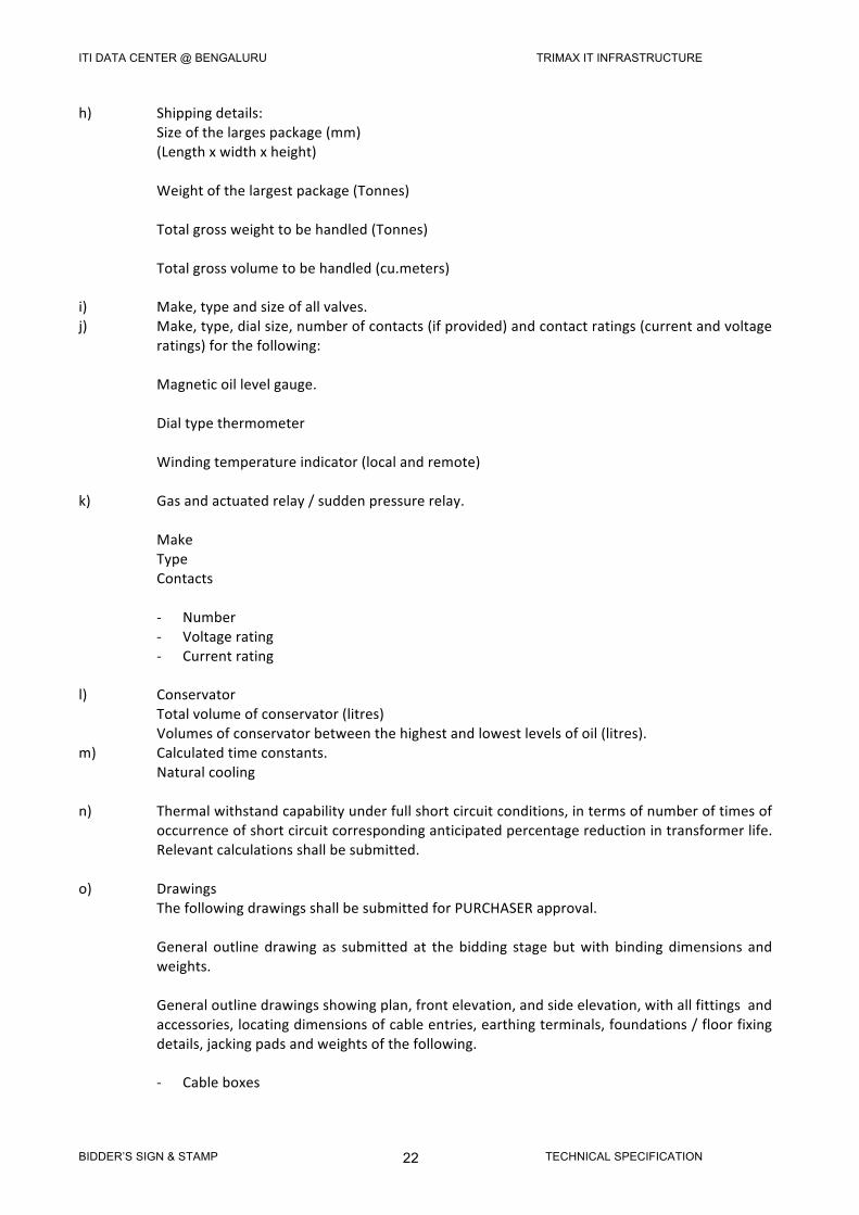
h) Shippingdetails: Sizeofthelargespackage(mm) (Lengthxwidthxheight) Weightofthelargestpackage(Tonnes) Totalgrossweighttobehandled(Tonnes) Totalgrossvolumetobehandled(cu.meters)i) Make,typeandsizeofallvalves.j) Make,type,dialsize,numberofcontacts(ifprovided)andcontactratings(currentandvoltage
ratings)forthefollowing: Magneticoillevelgauge. Dialtypethermometer Windingtemperatureindicator(localandremote)k) Gasandactuatedrelay/suddenpressurerelay. Make Type Contacts - Number - Voltagerating - Currentratingl) Conservator Totalvolumeofconservator(litres) Volumesofconservatorbetweenthehighestandlowestlevelsofoil(litres).m) Calculatedtimeconstants. Naturalcoolingn) Thermalwithstandcapabilityunderfullshortcircuitconditions,intermsofnumberoftimesof
occurrenceofshortcircuitcorrespondinganticipatedpercentagereductionintransformerlife.Relevantcalculationsshallbesubmitted.
o) Drawings ThefollowingdrawingsshallbesubmittedforPURCHASERapproval. General outline drawing as submitted at the bidding stage butwith binding dimensions and
weights. Generaloutlinedrawingsshowingplan,frontelevation,andsideelevation,withallfittingsand
accessories,locatingdimensionsofcableentries,earthingterminals,foundations/floorfixingdetails,jackingpadsandweightsofthefollowing.
- Cableboxes
ITI DATA CENTER @ BENGALURU TRIMAX IT INFRASTRUCTURE
BIDDER’S SIGN & STAMP TECHNICAL SPECIFICATION 23
- Disconnectingchambers - Bushings - Plan, elevation, terminal details, mounting details, make and type number, current and
voltagerating,creepagedistanceandprincipalcharacteristics. - Ratinganddiagramplates. - Marshallingboxterminalconnectionswiringdiagram.
ITI DATA CENTER @ BENGALURU TRIMAX IT INFRASTRUCTURE
BIDDER’S SIGN & STAMP TECHNICAL SPECIFICATION 24
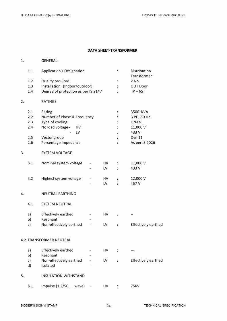
DATASHEET-TRANSFORMER1. GENERAL: 1.1 Application/Designation : Distribution Transformer 1.2 Qualityrequired : 2No. 1.3 Installation (Indoor/outdoor) : OUTDoor 1.4 DegreeofprotectionasperIS:2147 : IP–65 2. RATINGS 2.1 Rating : 3500KVA 2.2 NumberofPhase&Frequency : 3PH,50Hz 2.3 Typeofcooling : ONAN 2.4 Noloadvoltage- HV : 11,000V - LV : 433V 2.5 Vectorgroup : Dyn11 2.6 PercentageImpedance : AsperIS:20263. SYSTEMVOLTAGE 3.1 Nominalsystemvoltage - HV : 11,000V - LV : 433V 3.2 Highestsystemvoltage - HV : 12,000V - LV : 457V4. NEUTRALEARTHING 4.1 SYSTEMNEUTRAL a) Effectivelyearthed - HV : -- b) Resonant - c) Non-effectivelyearthed - LV : Effectivelyearthed 4.2 TRANSFORMERNEUTRAL a) Effectivelyearthed - HV : --- b) Resonant - c) Non-effectivelyearthed - LV : Effectivelyearthed d) Isolated - 5. INSULATIONWITHSTAND 5.1 Impulse(1.2/50__wave) - HV : 75KV
ITI DATA CENTER @ BENGALURU TRIMAX IT INFRASTRUCTURE
BIDDER’S SIGN & STAMP TECHNICAL SPECIFICATION 25
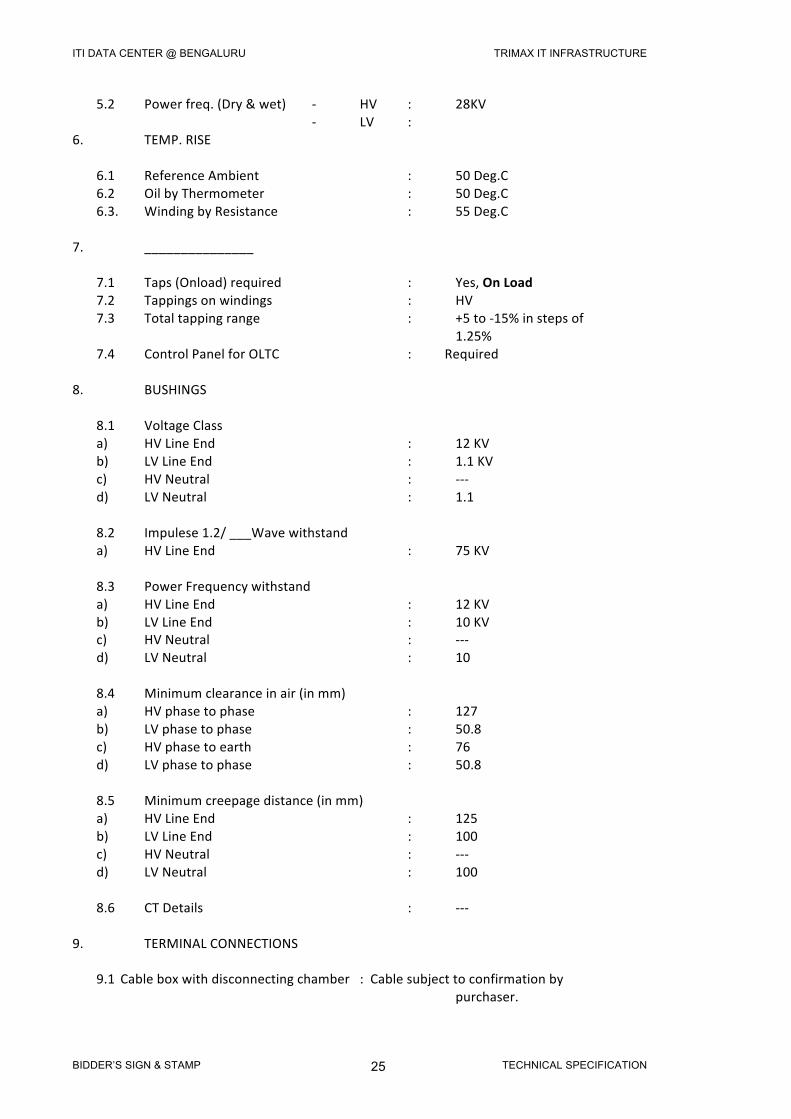
5.2 Powerfreq.(Dry&wet) - HV : 28KV - LV : 6. TEMP.RISE 6.1 ReferenceAmbient : 50Deg.C 6.2 OilbyThermometer : 50Deg.C 6.3. WindingbyResistance : 55Deg.C
7. _______________ 7.1 Taps(Onload)required : Yes,OnLoad 7.2 Tappingsonwindings : HV
7.3 Totaltappingrange : +5to-15%instepsof 1.25%7.4 ControlPanelforOLTC :Required
8. BUSHINGS 8.1 VoltageClass a) HVLineEnd : 12KV b) LVLineEnd : 1.1KV c) HVNeutral : --- d) LVNeutral : 1.1 8.2 Impulese1.2/___Wavewithstand a) HVLineEnd : 75KV 8.3 PowerFrequencywithstand a) HVLineEnd : 12KV b) LVLineEnd : 10KV c) HVNeutral : --- d) LVNeutral : 10 8.4 Minimumclearanceinair(inmm) a) HVphasetophase : 127 b) LVphasetophase : 50.8 c) HVphasetoearth : 76 d) LVphasetophase : 50.8 8.5 Minimumcreepagedistance(inmm) a) HVLineEnd : 125 b) LVLineEnd : 100 c) HVNeutral : --- d) LVNeutral : 100 8.6 CTDetails : ---9. TERMINALCONNECTIONS
9.1 Cableboxwithdisconnectingchamber :Cablesubjecttoconfirmationby purchaser.
ITI DATA CENTER @ BENGALURU TRIMAX IT INFRASTRUCTURE
BIDDER’S SIGN & STAMP TECHNICAL SPECIFICATION 26
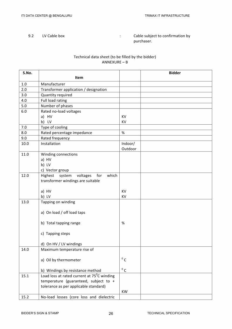
9.2 LVCablebox : Cablesubjecttoconfirmationby purchaser.
Technicaldatasheet(tobefilledbythebidder)
ANNEXURE–B
S.No.Item
Bidder
1.0 Manufacturer 2.0 Transformerapplication/designation 3.0 Quantityrequired 4.0 Fullloadrating 5.0 Numberofphases 6.0 Ratedno-loadvoltages
a)HVb)LV
KVKV
7.0 Typeofcooling 8.0 Ratedpercentageimpedance % 9.0 Ratedfrequency 10.0 Installation Indoor/
Outdoor
11.0 Windingconnectionsa)HVb)LVc)Vectorgroup
12.0 Highest system voltages for whichtransformerwindingsaresuitablea)HVb)LV
KVKV
13.0 Tappingonwindinga)Onload/offloadtapsb)Totaltappingrangec)Tappingstepsd)OnHV/LVwindings
%
14.0 Maximumtemperatureriseofa)Oilbythermometerb)Windingsbyresistancemethod
0C0C
15.1 Loadlossatratedcurrentat750Cwindingtemperature (guaranteed, subject to +toleranceasperapplicablestandard)
KW
15.2 No-load losses (core loss and dielectric
ITI DATA CENTER @ BENGALURU TRIMAX IT INFRASTRUCTURE
BIDDER’S SIGN & STAMP TECHNICAL SPECIFICATION 27
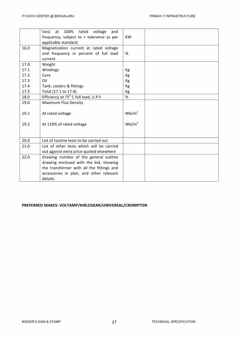
loss) at 100% rated voltage andfrequency, subject to + tolerance as perapplicablestandard.
KW
16.0 Magnetization current at rated voltageand frequency in percent of full loadcurrent
%
17.017.117.217.317.417.5
WeightWindingsCoreOilTank,coolers&fittingsTotal(17.1to17.4)
KgKgKgKgKg
18.0 Efficiencyat750Cfullload,U.P.F % 19.019.119.2
MaximumFluxDensityAtratedvoltageAt110%ofratedvoltage
Wb/m2Wb/m2
20.0 Listofroutineteststobecarriedout 21.0 List of other tests which will be carried
outagainstextrapricequotedelsewhere
22.0 Drawing number of the general outlinedrawing enclosed with the bid, showingthe transformer with all the fittings andaccessories in plan, and other relevantdetails.
PREFERREDMAKES:VOLTAMP/KIRLOSKAR/UNIVERSAL/CROMPTON