iris recognition with enhanced depth-of-field image aquisition
TRANSCRIPT

header for SPIE use
Iris recognition with enhanced depth-of-field image acquisition
Joseph van der Gracht*a, V. Paul Paucab , Harsha Settyb, Ramkumar Narayanswamyc, Robert J. Plemmonsb, Sudhakar Prasadd, and Todd Torgersenb
aHoloSpex, Inc.; bWake Forest University; cCDM Optics, Inc.; dUniversity of New Mexico
ABSTRACT
Automated iris recognition is a promising method for noninvasive verification of identity. Although it is noninvasive, the procedure requires considerable cooperation from the user. In typical acquisition systems, the subject must carefully position the head laterally to make sure that the captured iris falls within the field-of-view of the digital image acquisition system. Furthermore, the need for sufficient energy at the plane of the detector calls for a relatively fast optical system which results in a narrow depth-of-field. This latter issue requires the user to move the head back and forth until the iris is in good focus. In this paper, we address the depth-of-field problem by studying the effectiveness of specially designed aspheres that extend the depth-of-field of the image capture system. In this initial study, we concentrate on the cubic phase mask originally proposed by Dowski and Cathey. Laboratory experiments are used to produce representative captured irises with and without cubic asphere masks modifying the imaging system. The iris images are then presented to a well-known iris recognition algorithm proposed by Daugman. In some cases we present unrestored imagery and in other cases we attempt to restore the moderate blur introduced by the asphere. Our initial results show that the use of such aspheres does indeed relax the depth-of-field requirements even without restoration of the blurred images. Furthermore, we find that restorations that produce visually pleasing iris images often actually degrade the performance of the algorithm. Different restoration parameters are examined to determine their usefulness in relation to the recognition algorithm. Keywords: iris recognition, imaging, depth-of-field, restoration
1. INTRODUCTION The use of biometric signatures continues to gain increasing attention. Amongst the wide variety of available biometrics, iris signatures have a number of useful qualities including uniqueness of the signature and the relative ease of acquisition. The ease of acquiring a biometric signature is critical to the eventual acceptance of the method. While retinal scanners typically require the user to place his or her head in contact with a large acquisition unit, iris image acquisition simply requires a camera that is typically placed 15 to 20 inches from the user. This type of acquisition is less threatening to the user and has better chance of wide acceptance. A number of groups have explored the requirements on the image acquisition system1-5 and several implementations have already been put into commercial practice. A key problem with existing approaches to iris signature acquisition is the limited depth-of-field of the imaging system. In order to achieve reasonable lighting levels and exposure times, the optical system must have a high numerical aperture and a corresponding low F-number. Unfortunately, a high numerical aperture results in a corresponding small depth-of-field. Commercial implementations typically require the user to move his or her head back and forth with respect to the camera until the focus quality is good enough to provide a sufficiently high contrast iris signature. Some implementations rely on audio cues and others rely on visual cues to let the user know when the iris is at an appropriate distance from the camera. The process can be time consuming and may often serve as an obstacle to acceptance of the process in a daily use environment.
* [email protected]; HoloSpex, Inc., 6470 Freetown Rd. Ste 200-104, Columbia, MD 21044

In this study, we investigate the use of specially designed optical aspheres for extending the depth-of-field of iris recognition imaging systems. In particular, we study the use of a particular phase mask characterized by a cubic phase surface6. Insertion of the phase mask into the pupil plane of the imaging system produces a highly invariant modulation transfer function (MTF) over a large depth-of-field. The asphere does introduce blur relative to a conventional imaging system at best focus. Typically post-detection restoration can be used to remove the blur. A number of studies have shown that simple restoration techniques can produce excellent subjective image quality7-10. Such techniques often use mean square error as an image quality metric resulting in images that are visually pleasing. This metric however is not the most appropriate for automated iris recognition where a numerical algorithm is used, rather than a human viewer, to assess the collected image for iris identification purposes. Algorithms for post-detection restoration should be reconsidered in this context. We adopt a specific iris recognition algorithm proposed by Daugman1 for assessment of the collected image. This algorithm has already gained significant commercial acceptance. It is important to point out that Daugman’s algorithm was developed under the assumption of traditional image gathering without a cubic asphere. We note that, ideally, the recognition algorithm should be tailored to complement the modified imaging system. In fact, a fundamental approach would involve joint optimization of the algorithm and the aspheric surface. The present work approaches the less complex problem of investigating the interaction of the existing recognition algorithm with the cubic phase approach to depth-of-field extension. We compare the performance of the iris recognition algorithm over a large depth-of-field for the traditional image gathering approach and the cubic phase approach. Since, the recognition algorithm was designed for traditional well-focused images, it seems reasonable to restore the cubic blurred images prior to presentation to the algorithm. In this study, we examine how the recognition algorithm performs for both unrestored and Wiener-restored images. Results from this study will give insight into the more challenging problem of joint design of the recognition algorithm and the aspheric optical surface.
2. IMAGE GATHERING EXPERIMENT The basic premise of the laboratory experiment is to capture iris images both with a standard clear aperture imaging system and another system differing only by the insertion of cubic phase element at the pupil plane of the image capture system. The imaging system consists of a pair of achromatic doublets having focal lengths of 65 mm and 500 mm. The 65 mm focal length lens was placed closest to the detector and the configuration was designed to provide best focus at a distance of 500 mm. The lenses were placed close together with a circular aperture in between having a diameter of 7 mm. The circular aperture forms the aperture stop of the imaging system. For the cubic experiments, the cubic phase element is placed in close contact with the circular aperture. The effective focal length of the lens combination is approximately 57 mm and the resulting effective F-number is F/8. The imaging detector in the experiment can be modeled as a full fill factor (no space between pixels) device containing 1300 by 1030 square pixels each having a size of 6.7 microns. Near infrared (NIR) illumination is known to produce high contrast iris images1,2. We used a white light source delivered by a fiber bundle with a 260 nm wide spectral bandpass filter having a center wavelength of 830 nm. Appropriate measures were taken to keep light intensity below hazardous levels. A cross-section of the numerically calculated MTF for the standard imaging configuration is shown in Fig. 1(a). The MTF displays a large amount of variation from the best focus position to a defocus of 10 cm away from the camera. Furthermore, the nulls in the MTF suggest that large amounts of information are lost. Dowski and Cathey6 showed that the addition of a cubic phase element near the imaging system pupil plane yields a large amount of focus invariance and eliminates the presence of nulls in the MTF. The amount of phase deviation produced by the cubic element determines the amount of focus invariance. The phase profile of a general cubic phase element is given by
P(x, y) = exp( jα[ x 3 + y3 ]) for x ≤ 1, y ≤ 1, (1) where we employ a dimensionless x, y coordinate system and the choice of α governs the overall phase thickness of the mask. Large values of α correspond to large phase deviations and yield high focus invariance at the expense of low MTF values. The cubic element available for the experiment has a relatively small value of alpha of approximately 11 that is smaller than the recommended value of 20 or greater6. In practice, we find that operation with this small value

still provides significant focus invariance while providing relatively high MTF values. Future studies will further explore the choice of this parameter. The resultant MTF cross-sections are shown in Fig. 1(b). The MTF displays considerable invariance for lower frequencies, but begin to deviate for higher frequencies.
Figure 1: Numerically calculated MTF plots for: (a) the standard imaging system and (b) the cubic phase imaging system. In both plots the solid line represents best focus, the dashed line represents a defocus of –10 cm and the dash-dot line represents a defocus of –20 cm. The negative number indicates that the defocus corresponds to an object further from the camera than best focus. Representative images captured by the two imaging configurations are shown in Figs. 2 and 3. The rich iris texture is clearly seen in the best focus image produced by the standard imaging system. The defocused images for the standard configuration convey little visual evidence of iris texture. The imagery produced by the cubic imaging system is low contrast, but the iris texture can be seen even in the severe defocus cases of Figs. 3(a) and (c).
3. IRIS RECOGNITION WITH UNRESTORED IMAGERY A number of iris recognition algorithms have been proposed in the literature1-5. In this work, we rely on an implementation of the Daugman algorithm1. A good description of the algorithm details can be found in reference 1. We provide only a general description. The algorithm is composed of several distinct stages: iris segmentation, coordinate transformation, wavelet filtering and quantization of the wavelet coefficients. The quantized coefficients make up a binary code called the iris template that can be compared to see if it forms an acceptable match with another iris template. The segmentation stage involves finding the inner and outer boundaries of the iris. Specular reflections and low contrast imagery create challenging obstacles for the segmentation portion of the algorithm. The iris region is treated as a rubber sheet and is mapped into a

dimensionless polar coordinate system. This dimensionless mapping assumes that the physical iris stretches like an elastic membrane when the pupil size changes. The nature of the mapping accounts for the iris scale invariance of the algorithm.
Figure 2: Laboratory gathered images using a standard imaging system at three focus positions: (a) -15 cm away from best focus, (b) best focus, and (c) +11 cm away from best focus. A negative number means that the iris is placed further from the camera compared to best focus.
Figure 3: Laboratory gathered images using a cubic phase modified imaging system at three focus positions: (a) -15 cm away from best focus, (b) best focus, and (c) +11 cm away from best focus. A negative number means that the iris is placed further from the camera compared to best focus.
An iris template is generated by a series of wavelet filtering operations followed by quantization of the wavelet coefficients. The wavelet transformation occurs in the dimensionless polar coordinate system and consists of Gabor wavelets with the modulation frequency in the angular direction. The wavelet is applied on a number of closely spaced regions and each application generates a complex coefficient. The phase of the wavelet coefficients is quantized to one bit resulting in a binary code that is typically 2048 bits long. The fact that only phase information is retained suggests that the operation is attempting to localize transitions. Once an iris template has been generated for a particular iris, the code can be enrolled for later comparison. The iris template corresponding to a different image capture of that same iris should be similar to the original code. Daugman advocates a simple Hamming distance measurement to determine the similarity of two iris templates. The Hamming distance between an enrolled iris template and a candidate iris template must be below 0.32 for a match. This threshold was determined by Daugman after extensive investigation and consideration of iris statistics with a goal of eliminating false matches 4.
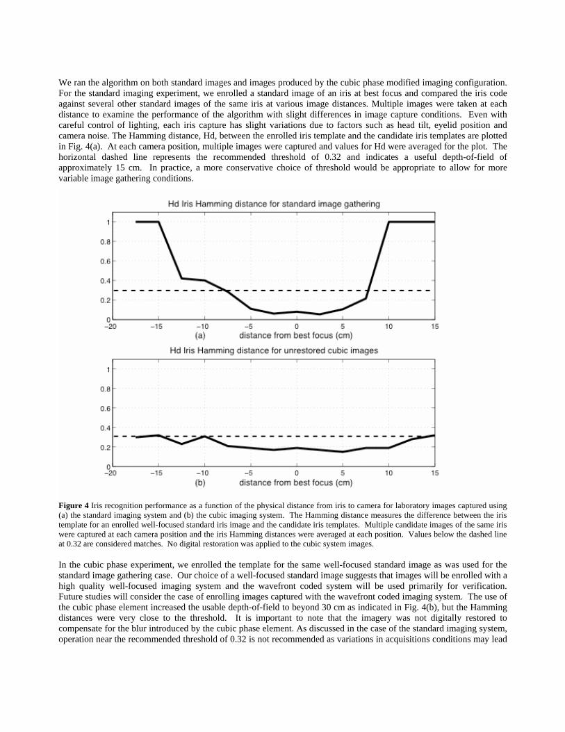
We ran the algorithm on both standard images and images produced by the cubic phase modified imaging configuration. For the standard imaging experiment, we enrolled a standard image of an iris at best focus and compared the iris code against several other standard images of the same iris at various image distances. Multiple images were taken at each distance to examine the performance of the algorithm with slight differences in image capture conditions. Even with careful control of lighting, each iris capture has slight variations due to factors such as head tilt, eyelid position and camera noise. The Hamming distance, Hd, between the enrolled iris template and the candidate iris templates are plotted in Fig. 4(a). At each camera position, multiple images were captured and values for Hd were averaged for the plot. The horizontal dashed line represents the recommended threshold of 0.32 and indicates a useful depth-of-field of approximately 15 cm. In practice, a more conservative choice of threshold would be appropriate to allow for more variable image gathering conditions.
Figure 4 Iris recognition performance as a function of the physical distance from iris to camera for laboratory images captured using (a) the standard imaging system and (b) the cubic imaging system. The Hamming distance measures the difference between the iris template for an enrolled well-focused standard iris image and the candidate iris templates. Multiple candidate images of the same iris were captured at each camera position and the iris Hamming distances were averaged at each position. Values below the dashed line at 0.32 are considered matches. No digital restoration was applied to the cubic system images.
In the cubic phase experiment, we enrolled the template for the same well-focused standard image as was used for the standard image gathering case. Our choice of a well-focused standard image suggests that images will be enrolled with a high quality well-focused imaging system and the wavefront coded system will be used primarily for verification. Future studies will consider the case of enrolling images captured with the wavefront coded imaging system. The use of the cubic phase element increased the usable depth-of-field to beyond 30 cm as indicated in Fig. 4(b), but the Hamming distances were very close to the threshold. It is important to note that the imagery was not digitally restored to compensate for the blur introduced by the cubic phase element. As discussed in the case of the standard imaging system, operation near the recommended threshold of 0.32 is not recommended as variations in acquisitions conditions may lead

to excessive failure rates. In the next section we discuss the use of digital restoration to improve iris template matching scores further below the threshold.
4. IMAGE RESTORATION AND RECOGNITION PERFORMANCE The Daugman algorithm was designed for optimal performance with well-focused imagery. While the iris recognition results using cubic blurred imagery provide extended depth-of-field, the overall quality of the matches as compared with well-focused imagery were poorer as evidenced by higher Hamming distance values. Digital image restoration can be applied to the blurred imagery to more closely approximate a well-focused image. We chose to use a simple Wiener restoration11 approach to investigate the effect of image restoration on the performance of the algorithm. The Wiener restoration filter is described in the frequency domain as
W (u,ν ) =H*(u,ν )
H(u,v) 2 + SNR( )-2 ˆ Φ N u,v( )/ ˆ Φ L u,v( ), (2)
where H(u,v) is the imaging system transfer function including the effects of the imaging optics as well as the detector,
is the object power spectrum normalized to unit energy, ˆ Φ L u,v( ) ˆ Φ N u,v( ) is the unit normalized electronic detection noise power spectrum, and SNR is the estimated rms signal-to-noise ratio. In practice, we use SNR as a regularization parameter to adjust the response of the restoration filter. Larger values of SNR produce filters that provide higher boosting of higher spatial frequencies at the expense of increased noise in the restored imagery. The model for the expected object power spectrum also affects the behavior of the Wiener restoration filter. Since we did not have a specific model for expected iris power spectral density, we followed Fales12 and assumed that the form of the normalized object power spectrum is given by
ˆ Φ L u, v( )=2πµ r
2
1+ 2πµr ρ( )2[ ]3 2 , (3)
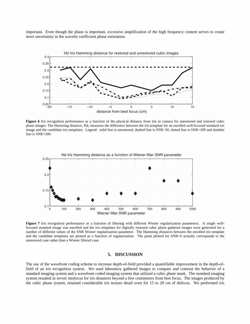
where , and ρ2 = u2 + v 2 µr is the mean spatial detail (MSD). We fixed the MSD at a length of 3 detector pixels. The choice of MSD can also be varied to affect the regularization properties of the filtering strategy. Smaller values of MSD produce filters that provide greater boosting of high frequencies with the attendant higher contrast imagery at the expense of noise. We estimated the imaging system transfer function from experimentally gathered point spread functions (PSF). We gathered several images of a bright point at the best focus position to provide an estimate of the system PSF. We then registered and averaged those PSF’s and used the Fast Fourier Transform to obtain an estimate of the imaging system transfer function. We then calculated a variety of candidate restoration filters corresponding to different choices for the value of SNR under the assumption of uniform noise. Higher values of SNR lead to more aggressive restoration filters in the sense that they provide more high frequency boosting. We restored individual frames of cubic images gathered in the best focus position using this Wiener filtering strategy. Figure 5(a) shows the restoration result with the lower value of SNR=50. Fig. 5(b) shows the result with a higher value of SNR=200 and Figure 5(c) shows the restoration result with the highest value of SNR=500. Qualitative observation of the images confirms that filters designed with higher values of SNR do provide improved contrast at the expense of higher granular noise artifacts. Many human observers would likely prefer the restored images corresponding to the higher SNR values since the iris texture pattern is readily observable.

Figure 5 Restored images using Wiener filters under the assumption of different SNR (a) 50, (b) 200 and (c) 500. The pupil was artificially forced to zero after restoration to overcome difficulties in the iris boundary localization step. In order to test the utility of restoration, we restored the set of cubic images used to create the plot in Fig. 4 and performed iris recognition testing on the restored images. We used three different restoration filters to examine the effect of filter properties on iris recognition. The three different filters corresponded to Wiener regularization parameters of SNR=50, 200 and 500. The system blur function used to compute the filter was taken from the average of a set experimentally measured PSFs produced with the cubic phase mask in place. For each set of restored images, we enrolled a well-focused standard image and measured the Hamming distance between the resultant iris template and the enrolled standard image iris template. In all cases, the restoration filters produced imagery that outperformed the unrestored imagery as seen in Fig. 6. The best recognition results correspond to the images restored with the low value of SNR=50 and SNR=200. It is interesting to note that the more visually pleasing result produced by SNR=500 did not perform as well as the blurrier images produced by SNR=50. In some cases, the restoration produced unwanted artifacts in the region of the bright specular reflection in the iris pupil. These restoration artifacts sometimes created failures in finding the iris pupil boundary. Since we were interested in the effect of the cubic element on the iris template, we artificially forced the pupil region to zero to make the segmentation problem more tractable. The variations in recognition results with varying SNR parameter suggests that an optimal choice of SNR parameter might yield improved results. We performed a parametric study to find an optimal SNR value. Once again, a single well-focused standard image was used to create an iris code template. A group of ten cubic phase images at the nominal best focus position were used in testing. Wiener restorations were computed using filters created with a large number of different SNR values. We performed a fine grain search over SNR values from 0 to 100 in increments of 10. Next we performed a coarser search in increments of 100 from 100 to 1000. The average iris template match was computed for the ten restored images for each value of SNR regularization parameter. The restoration artifacts surrounding the specular reflection created severe difficulties with segmentation for higher values of SNR. In order to concentrate on the iris template behavior, we discarded segmentation failures before averaging. The results of Fig. 7 indicate that even slight amounts of restoration have a significant impact on recognition performance. The search suggests that values of SNR ranging from 100 to 200 will result in the best performance. Higher values of SNR parameter create a modest degradation in the iris template matching and present difficulties in performing the iris segmentation. The camera used in the experiment has a high performance CCD that produces low noise imagery. Lesser quality cameras will produce significantly more noise and the resulting amplified noise in restored imagery may create further problems when restoring with filters created with high values of the SNR regularization parameter. While human viewers may subjectively prefer the higher contrast images produced with the more aggressive restoration strategies illustrated by the restorations in Figs. 5(b) and (c), the performance of the iris algorithm does not require large amounts of high frequency amplification. One reason for good performance of the algorithm with only modest restoration is that the Gabor wavelets employed in the wavelet transformation stage of the algorithm are already tuned to extract the important mid-frequency features. It is also instructive to remember that the recognition algorithm is based on the phase of the coefficients rather than the magnitude. The use of phase suggests that the relative amplitude is less
important. Even though the phase is important, excessive amplification of the high frequency content serves to create more uncertainty in the wavelet coefficient phase estimation.
Figure 6 Iris recognition performance as a function of the physical distance from iris to camera for unrestored and restored cubic phase images. The Hamming distance, Hd, measures the difference between the iris template for an enrolled well-focused standard iris image and the candidate iris templates. Legend: solid line is unrestored, dashed line is SNR=50, dotted line is SNR=200 and dashdot line is SNR=500.
Figure 7 Iris recognition performance as a function of filtering with different Wiener regularization parameters. A single well-focused standard image was enrolled and the iris templates for digitally restored cubic phase gathered images were generated for a number of different values of the SNR Wiener regularization parameter. The Hamming distances between the enrolled iris template and the candidate templates are plotted as a function of regularization. The point plotted for SNR=0 actually corresponds to the unrestored case rather than a Wiener filtered case.
5. DISCUSSION The use of the wavefront coding scheme to increase depth-of-field provided a quantifiable improvement in the depth-of-field of an iris recognition system. We used laboratory gathered images to compare and contrast the behavior of a standard imaging system and a wavefront coded imaging system that utilized a cubic phase mask. The standard imaging system resulted in severe misfocus for iris distances beyond a few centimeters from best focus. The images produced by the cubic phase system, retained considerable iris texture detail even for 15 to 20 cm of defocus. We performed iris
recognition experiments on the laboratory data using an implementation of the Daugman iris recognition algorithm. The recognition experiments using the unrestored wavefront coded imagery provided more than a twofold improvement in depth-of-field compared to a standard imaging system. The fact that the iris algorithm produced matches with unrestored imagery is consistent with Daugman’s claim that his algorithm can tolerate considerable blur4. The feature extraction portion of the algorithm is essentially making local estimates of phase and should be robust to the lower contrast resulting from the optical blur produced by the cubic phase mask. This trend suggests that a stronger phase mask might yield further improvement in depth-of-field without excessive degradation of iris recognition scores. The use of post-detection restoration improved iris recognition performance. We restricted our attention to simple Wiener restoration of the imagery. Subjective evaluation of the restored imagery suggested the use of filter parameters that provide rich detail in the restored imagery. In practice, those parameters actually produced inferior recognition results in comparison with the use of imagery restored with less high frequency amplification. We did find that lower values of SNR parameters in the Wiener filter construction produced mildly restored imagery that produced improvements in iris recognition performance relative to the unrestored cubic imagery results. We conjecture that the more aggressive filters introduced excessive noise and restoration artifacts that increased the variability of the iris signature. The use of more sophisticated image restoration techniques that take more advantage of a priori information may yield further performance improvements13,14. These preliminary results demonstrate promise for the use of wavefront modifying masks at the exit pupil plane of an iris recognition image acquisition system in order to extend the depth-of-field. The parameters of the optical phase mask and the post-detection restoration filtering were not optimized to maximize the utility of the approach. The results from these experiments will be used to motivate a more fundamental approach to designing a robust iris image acquisition system that makes more efficient use of optical phase masks and digital filtering strategies. Relevant metrics can be built into the optimization algorithms that are used to specify optimal phase masks15,16. Joint optimization of the phase mask with the iris recognition algorithm parameters has the potential to yield further improvement.
6. ACKNOWLEDGEMENTS This work was accomplished with the support of the Army Research Office under DOD Grant # DAAD19-00-1-0540. Iridian Technologies, Inc. provided us with the implementation of the iris recognition algorithm. We would also like to thank Ulf Cahn von Seelen and James Cambier of Iridan Technologies, Inc. as well as John Daugman of Cambridge University for many helpful discussions concerning the recognition algorithm.
7. REFERENCES
1. J. G. Daugman, “High confidence visual recognition of person by a test of statistical independence,” IEEE Trans. PAMI 15, 1148-1161 (1993). 2. R.P. Wildes, “Automated iris recognition: An emerging biometric technology,” Proceedings of the IEEE 85 1348-1363 (1997). 3. Y. Zhu , T. Tan and Y. Wang, "Biometric personal identification based on iris pattern,” ICPR2000: the 15th International Conference on Pattern Recognition, Barcelona, Spain 805-808 (2002). 4. J. G. Daugman, "The importance of being random: statistical principles of iris recognition", Patt. Rec., 36, 279-291 (2003).
5. C. Tisse, L. Martin ,L. Torres ,M. Robert : Iris recognition system for person identification. PRIS 2002 : 186-199 (2002).

6. E. R. Dowski, Jr. and W. T. Cathey, “Extended depth of field through wavefront coding,” Appl. Opt. 34, 1859-1866, (1995). 7. J. van der Gracht, E. R. Dowski, M. Taylor, D. Deaver, “Broadband behavior of an optical-digital focus-invariant system,” Opt. Lett. 21, 919-921 (1996). 8. W. T. Cathey and E. Dowski, A new paradigm for imaging systems, Applied Optics, 41, 6080, (2002). 9. E. Dowski and K. Kubala, Modeling of wavefront coded imaging systems, Proc. SPIE. 4736, 116-126 (2003). 10. J. van der Gracht, J.G. Nagy, V.P. Pauca and R.J. Plemmons, "Iterative restoration of wavefront coded imagery for focus invariance," OSA Trends in Optics and Photonics (TOPS), Integrated Computational Imaging Systems, OSA Technical Digest, Washington, D.C., 2-4 (2001). 11. R.C Gonzales and R.E. Woods in Digital Image Processing, Addison-Wesley, pp. 279-280, (1992). 12. C. L. Fales, F. O. Huck, and R. W. Samms, "Imaging system design for improved information capacity," Appl. Opt. 23, pp. 873-888, (1984). 13. S. Prasad, “Statistical-information-based performance criteria for Richardson-Lucy image deblurring” JOSA A, 19, 1286-1296, (2002). 14. G. Archer and D. Titterington, “On some Bayesian/regularization methods for image restoration,” IEEE Trans. Image Processing, 4(7):989—995, (1995). 15. S. Prasad, T.C. Torgersen, V. P. Pauca, R. J. Plemmons, and J. van der Gracht, “Engineering the pupil phase to improve image quality,” Proc. SPIE 5108, 1-12, (2003). 16. P. Pauca, S. Prasad, R. J. Plemmons, T. C. Torgersen and J. van der Gracht, Integrated Optical-digital approaches for enhancing image restoration and focus invariance, Proc. SPIE 5205, 348-357, (2003).