inventor tips & tricks - synergis university · inventor tips & tricks hosted by jim swain...
TRANSCRIPT

Inventor Tips & Tricks
Hosted by Jim Swain and Mark Lancaster

Inventor Tips & Tricks

Sketch @ Offset Plane
Starting a sketch
that’s offset to
this plane/face
Left/hold/drag –
Apply sketch
offset distance
Select face to
start sketch
J

Trim CTRL/Trim Line
Trimming away selected
line would force me to
select it twice due to
the inferred of the
trimmed line with other
geometry
Hold down CTRL key and
select cutting line
RMC and select
CONTINUE in order to
trim line to cutting edge
J

Line – Restart
Currently
sketching.. Now
want to start
sketching from a
different point
(red arrow)
RMC and Restart
(and select new
starting point)

Bypass Constraints
Automatically
determining
perpendicularTemporary bypass
inferred
constraints
J

Sketch Perpendicular Line
Sketch and apply
perpendicular
constraint
Hold and Drag to
draw perpendicular

Inventor Tips & Tricks

EOP Marker – Starting Over
Removing all
highlighted featuresDrag EOP to correct
location, RMC on EOP
and Delete All
Features

Always in the Middle
Center hole in part
face no matter
the dimensions
Define work
point – Center
Point of Loop
of Edges
Select work
point as hole
placement
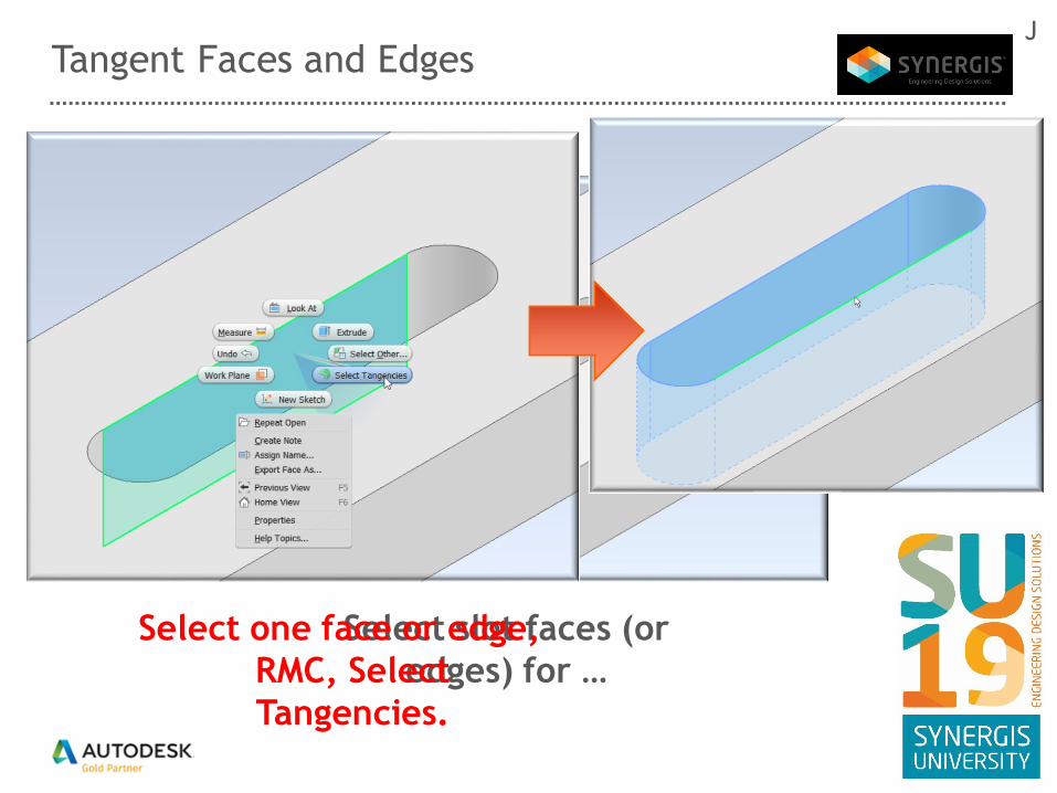
Tangent Faces and Edges
Select slot faces (or
edges) for …
Select one face or edge,
RMC, Select
Tangencies.
J

Inventor Tips & TricksJ

Project Flat Pattern
Mounting slot across
different sheet metal
faces and bends
Project Flat Pattern
information and sketch
slots as needed
J

Inventor Tips & TricksJ

Constraining on the Fly – ALT DRAG
Constrain hardware
to plate as shown
Hold <ALT> key and
dragging to constrain in
less time/steps
J

Find component – Method #1
Locate component
in model?
RMC and Find in
Window
J

Find component – Method #2
Locate component
in model?
Select and “END”
key
J

Find component – Method #3
Locate component
in model?Toggle to Zoom
Select and select
part in browser

Toggle Visibility/Transparent
From the model browser
or graphics screen, RMC
and select Visibility or
Transparent
Select component in
model browser or
graphics screen and Toggle - Transparent
Toggle - Visibility
J

Change Selection Priority (on the fly)
Want to select this
part of the sub-assy
RMB
J

Measure to Assemble
Hold and Drag
RMC

Inventor Tips & TricksJ

Section View
Break section view
projection
While placing
J

Center of Gravity/Drawing View
Display calculated
center of gravity
(COG) in drawing view
Locate model under
drawing view, RMC
and select COG
J
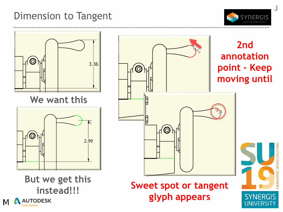
Dimension to Tangent
But we get this
instead!!!
We want this
Sweet spot or tangent
glyph appears
2nd
annotation
point - Keep
moving until
J
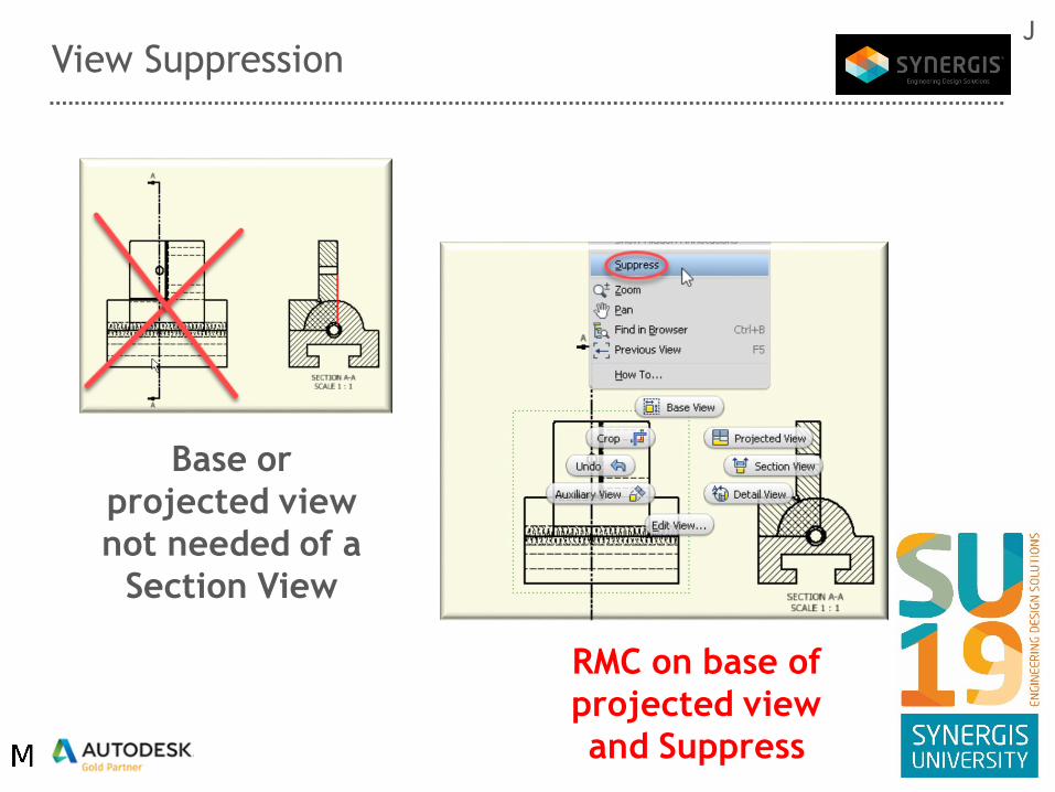
View Suppression
Base or
projected view
not needed of a
Section View
RMC on base of
projected view
and Suppress
J

Apparent Intersection
Achieving this
type of dimension
RMC
Hover & select intersecting
geometry
J

Note - Follow View
Drawing note
follows a drawing
view
Create
standard leader
text
RMC leader/text &
Delete Leader
J

Detail View to follow
Dimensional
modifications could
cause detailed
view to be
incorrect
J
RMC on Detail View
indicator, select Attach
and where you want to
attach the boundary too

Start Drawing – Toggle File DefaultsJ
Numerous models
loaded, base view
defaults to last active
Cancel drawing view and toggle
back to model needed
Toggle back to
drawing and start
base view

Inventor Tips & Tricks

EOP Marker – File Size Reduction
File Size w/EOP @ ENDDrag EOP or
RMC “Move
EOP”

Starting with Blank State
New “Standard”
part/assembly/presentation/
drawing
Blank to start
with

Inventor Tips & Tricks

Inventor Save Status
Determine why an Inventor
file needs to be saved

Body Integer Checker (part/assembly)
Customer Issue:
Unable to extrude 2
sketches

First & Last Saved Version
Window/File
Explorer, RMC and
iProperties
Details tab

Sharing….
Do you have an Inventor
tips & tricks you would like
to share with everyone?

Questions