intruction espm(airbus)
DESCRIPTION
documents referent ESPM A330TRANSCRIPT

Customer : GENType : ALLRev. Date : Apr 01, 2013
Manual : ESPMSelected applicability :
INTRODUCTION - DESCRIPTION AND OPERATION
Print date : April 24, 2013 Page 1 of 44
INTRODUCTION - DESCRIPTION AND OPERATION
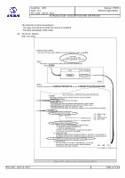
1. GeneralThe Electrical Standard Practices Manual (ESPM) gives descriptive data and procedures for the electricalinstallations on all aircraft of the AIRBUS family.The standard practices information in this manual tells you how to do maintenance and repairs on the standardelectrical items and thus ensure the continued airworthiness of the aircraft.
NOTE: For the obsolescence/interchangeability status of the tools, refer to the Tool Equipment Manual. (TEM)
NOTE: The Electrical Standard Practices data related to Power Plant is shown in the AMM 70-71-XX.
NOTE: There are several Chapter 20, depending on the vendor responsible for the system (ECE, Honeywell,etc.) but whatever the vendor, their chapter 20 follows the same layout.
NOTE: For users of this manualIf you cannot find the data or a procedure you need to ensure the continued airworthiness of the air-craft, or if you think that the information given is not complete, contact Airbus.
The ESPM is broken down in two main chapters:- Chapter 00 (common part) with: - General, How to use (00-INTRO) - Indexes- Chapter 20 with: - Safety Practices (20-10-00) - Tools (20-25-XX) - Subjects related to standard rules and
recommendations (20-3X-XX): Specific areas (20-31-XX) . Identification/marking (20-32-XX) Wire harnesses (20-33-XX)
- Subjects related to standard electrical items and connecting parts with their description (P/Nidentification and characteristics) and their related processes (connection procedure or connection table)(20-4X-XX):
Sleeves, End Caps and Ferrules (20-42-XX) . Splices and Pressure Seals (20-43-XX) Connectors and Terminal Blocks (20-44-XX) Miscellaneous Electrical Items (20-45-XX) Circuit breaker, Relay and Relay Base (20-46-XX) Terminals and Contacts (20-48-XX)
- Subjects related to maintenance processes (20-5X-XX): Standard Processes (20-51-XX) . Inspection/Check and Test (20-52-XX) Repair Processes (20-53-XX) Protection during Maintenance Checks (20-54-XX) Cleaning (20-55-XX)
If any part or all of the ESPM is translated, the official version is the original English-language versionproduced by AIRBUS.
2. CorrespondenceCorrespondence concerning this publication should be directed to: ----------------------------------------------------------------- AIRBUS SAS Technical Data Support and Services 1 Rond Point Maurice BELLONTE 31707 Blagnac Cedex FRANCE

Customer : GENType : ALLRev. Date : Apr 01, 2013
Manual : ESPMSelected applicability :
INTRODUCTION - DESCRIPTION AND OPERATION
Print date : April 24, 2013 Page 2 of 44
-----------------------------------------------------------------Or by the "Request for Information/Revision" form.
3. Definitions
A. Definition of TermsThe terms below are used in the ESPM and are defined as follows:- Standard Practices: Standard industry practices that are not specific to AIRBUS aircraft. Procedures
specific to AIRBUS aircraft and applicable to several systems.- Torque: Term used when a procedure requires a specific torque value.- Tighten: Term used when no specific torque value is required.- WARNING: Calls attention to use of materials, processes, methods, procedures or limits that you
must obey precisely to prevent injury or death to persons.- CAUTION: Calls attention to methods and procedures that you must obey to prevent damage to
equipment.- NOTE: Calls attention to methods which make the job easier or give supplementary or explanatory
information.
B. Part Number (P/N) ConstructionIt is only with a P/N (not with a FIN) that you can access to the ESPM information.The P/Ns listed in the ESPM are made up of two parts:- A basic element which is the standard number/family.- A suffix which defines the item. e.g. Basic element (standard) + suffix(item) = Full P/N NSA936504 TC0607 NSA936504TC0607 ASNE0261 CF24 E0261CF24
NOTE: For ASNE standards, the 3 letters "A, S, N" are omitted in the P/N.For clarity, only the suffix (item) (e.g. E0617 for ASNE0617) is shown in the tables.However, you can identify the full P/N because the applicable standard number is always shownon the page. (In the title or/and on top of the table)
NOTE: For tool military part number (MIL), the P/N consists of the letter M and of the basic specificationnumber.
e.g.: M 81969 / 01-01 - ----- -- -- | | | | | | | ----- Dash number from specification sheet | | -------- Specification sheet number | -------------- General specification number ------------------ "M" Military part number indicator
4. Units of Measurement
A. AbbreviationsAIRBUS Technical Publications use the metric and non-metric systems of measurement. The systemused in the original reference documents is shown first, followed by the conversion into the other systemin brackets.-------------------------------------------------------------------------------| U.S. CUSTOMARY SYSTEM | SI-METRIC MEASUREMENT SYSTEM ||------------------------------------|----------------------------------------|| ABBREVIATION | DEFINITION |ABBREVIATION | DEFINITION ||---------------|--------------------|-------------|--------------------------|| deg.F | Degrees Fahrenheit | deg.C | Degrees Celsius || ft. | Foot | m | Meter || USgal | US Gallon | l | Liter || USquart | US Quart | l | Liter |

Customer : GENType : ALLRev. Date : Apr 01, 2013
Manual : ESPMSelected applicability :
INTRODUCTION - DESCRIPTION AND OPERATION
Print date : April 24, 2013 Page 3 of 44
| in. | Inch | mm | Millimeter || in.2 | Square Inch | mm2 | Square Millimeter || in.2 | Square Inch | cm2 | Square Centimeter || lb | Pound | kg | Kilogram || lbf | Pound force | daN | Deca Newton || lbf.in. | Pound Force-Inch | m.daN | Meter deca Newton || | (Torque) | | || lbf.ft | Pound Force-Foot | m.daN | Meter deca Newton || | (Torque) | | || in.Hg | Inch of Mercury | hPa | Hecto Pascal || oz | Ounce (Weight) | g | Gram || psi | Pound Square Inch | bar | Bar || lb.min | Pound per minute | kg.min | Kilogram per minute || USgal.min | US Gallon per | l.min | Liter per minute || | | W/dm2 | Watt per square decimeter|| | | cc | Cubic Centimeter |-------------------------------------------------------------------------------
B. Conversion TablesTemperature conversion from degrees Celsius (deg.C) to degrees Fahrenheit (deg.F):deg.F = 1.8 x deg.C + 32.-------------------------------------------------------------------------------FROM: S.I.Measurement System TO: US Customary System------------------------------------------------------------------------------- 1 bar = 14.5037 psi 1 mm2 = 0.0016 in.2 1 cm2 = 0.1550 in.2 1 daN = 2.2481 lbf 1 g = 0.0353 oz 1 hPa = 0.0295 in.Hg 1 kg = 2.2046 lb 1 kg.min = 2.2046 lb.min 1 l = 0.2641 USgal 1 l = 1.057 USquart 1 l.min = 0.2641 USgal.min 1 m.daN = 88.4956 lbf.in 1 m.daN = 7.3801 lbf.ft 1 m = 3.2809 ft 1 mm = 0.0394 in 1 cm3 = 0.06102 in3 1 hPa = 0.0145 psi---------------------------------------------------------------------------------------------------------------------------------------------------------FROM: US Customary System TO: S.I.Measurement System----------------------------------------------------------------------------- 1 psi = 0.0689 bar 1 in.2 = 645.1600 mm2 1 in.2 = 6.4516 cm2 1 lbf = 0.4448 daN 1 oz = 28.3495 g 1 in.Hg = 33.8640 hPa 1 lb = 0.4536 kg 1 lb.min = 0.4536 kg min 1 USgal = 3.7854 l 1 USgal.min = 3.7854 l.min

Customer : GENType : ALLRev. Date : Apr 01, 2013
Manual : ESPMSelected applicability :
INTRODUCTION - DESCRIPTION AND OPERATION
Print date : April 24, 2013 Page 4 of 44
1 USquart = 0.9464 l 1 lbf.in = 0.0113 m.daN 1 lbf.ft = 0.1356 m.daN 1 ft = 0.3048 m 1 in = 25.4 mm 1 in3 = 16.3871 cm3 1 in.Hg = 0.491 psi-----------------------------------------------------------------------------Temperature conversion from degrees Fahrenheit (deg.F) to degrees Celsius (deg.C):deg.C = 0.5555 x (deg.F - 32)
5. Glossary of Abbreviations used in the ESPM
ABBREVIATION SIGNIFICATIONA AmberA AlternateA/C AircraftAC Alternating currentADF Automatic Direction FinderAECMA The European Association of Aerospace IndustriesAg SilverAINS Aircraft Information Network SystemAl AluminumAPU Auxiliary Power UnitARINC Aeronautical Radio INCorporatedARPT AirportASCII American Standard Code for Information InterchangeASM Aircraft Schematics ManualASSY AssemblyATA Air Transport Association of AmericaATC Air Traffic ControlATE Automatic Test EquipmentATLAS Abbreviated Test Language for All SystemsAUTO AutomaticAUX AuxiliaryAVAIL AvailableAVNCS AvionicsAWM Aircraft Wiring ManualAWY AirwayB AWY BlueBK BlackBR BrownBUS BusbarC CloseC ClearC CelsiusC CentigradeC/B Circuit BreakerC/L Check ListCAB CabinCINS Cabin Information Network SystemCO Carbon Dioxide

Customer : GENType : ALLRev. Date : Apr 01, 2013
Manual : ESPMSelected applicability :
INTRODUCTION - DESCRIPTION AND OPERATION
Print date : April 24, 2013 Page 5 of 44
ABBREVIATION SIGNIFICATIONCOM CommunicationCOMSAT Communication SatelliteCSK CountersinksCu CopperCw ClockwiseDC Direct CurrentD/O Description and OperationDIA DiameterDME Distance Measuring EquipmentDNC Do not ConnectEFCS Electrical Flight Control SystemELEC Electric, Electrical, ElectricityELT Emergency Locator TransmitterEMC Electromagnetic CompatibilityES SpainETFE Ethylene-TetrafluorethyleneEU EuropeEQPT EquipmentEWIS Electrical Wiring Interconnection SystemF FahrenheitFEP PerfluorethylenepropyleneFIG FigureFIN Functional Item NumberFR FranceFWD ForwardG GreenGB Great BritainGND GroundGPS Global Positioning SystemGY GreyH Hot (Electrical Point)HF High FrequencyIDENT Identification, Identifier, IdentifyIDG Integrated Drive GeneratorIPC Illustrated Parts CatalogISO International Standardization OrganizationISOL IsolatedIT ItalyL LengthL/G Landing gearLED Light Emitting DiodeLOC LocalizerMAG MagneticMAINT MaintenanceMAN ManualMAX MaximumMED MediumMID MiddleMIL Military Standard

Customer : GENType : ALLRev. Date : Apr 01, 2013
Manual : ESPMSelected applicability :
INTRODUCTION - DESCRIPTION AND OPERATION
Print date : April 24, 2013 Page 6 of 44
ABBREVIATION SIGNIFICATIONMIN MinimumMISC MiscellaneousMLS Microwave Landing SystemMS Military StandardNAS Navy and Army StandardNAS National Aerospace StandardNi NickelNiAl AlumelNiCu ChromelNL NetherlandNo NumberO OrangeOK CorrectOPT OptionalP PurplePA PolyamideP/B PushbuttonP/BSW Pushbutton SwitchPCB Print Circuit Board (idem LRM)PE PolyethylenePFA Perfluoroalkoxy-CopolymerePI PolyimidePK PinkP/N Part NumberPTFE PolytetrafluorethylenePVC PolyvinylchlorideR RedRCPT ReceptacleREF ReferenceRF Radio FrequencyRFI Radio Frequency InterferenceRH RightS Sensitive (or Safety)SATCOM Satellite CommunicationSHLD ShieldSI SiliconeSn TinSPCW Silver plated copperweldSt SteelSTD StandardSW SwitchTACS Taxiing Aid Camera SystemTCAS Traffic Alert and Collision Avoidance SystemTEMP TemperatureTFTS Terrestrial Flight Telephone SystemTX Transmission (TCAS to transponder)UHF Ultra High FrequencyUS United StatesV Violet

Customer : GENType : ALLRev. Date : Apr 01, 2013
Manual : ESPMSelected applicability :
INTRODUCTION - DESCRIPTION AND OPERATION
Print date : April 24, 2013 Page 7 of 44
ABBREVIATION SIGNIFICATIONVHF Very High FrequencyVM VoltmeterVOR VHF Omnidirectional RangeUV UltravioletW WeightW WhiteWARN WarningXL-ETFE Cross linked Ethylene-TetrafluorethyleneY Yellow
6. EffectivityThe effectivity of a page is given in the effectivity (Selected effectivity) statement in the top right hand corner ofthe page.For the ESPM, this effectivity is always 'ALL' because ESPM is a generic manual.Thus, the effectivitystatement of each page is ALL.
7. Revision Service
A. GeneralThe revision service is on a six-month basis.You can acces to ESPM data in the digital format products that follow:- AirNav/Maintenace (DVD)- AirNav/Associated data (DVD)- SGML The Temporary Revision (TR) service to the ESPM is issued as necessary to alert the
customer on a major technical data change and give temporary instructions before the next regularrevision. Each temporary revision will be usually incorporated into the ESPM in the next regularrevision.
B. Filing InstructionsThere are no filing instructions with AirNav because the manual is not page- oriented.- Highlights (HL) are shown at the front of ESPM (and not at chapter level), and give a list of chapters orillustrations which have been modified at the revision.
C. Revision IndicationIn the current revision of ESPM, the revision changes are identified by a yellow background on the screento highlight the changes between two revisions.
D. Temporary Revisions (TR)For AirNav/Maintenance or AirNav Associated Data, the revisions are given in digital format via Airbusworld and in CD format. You must load these TRs as soon as you received them.At each revision, all TR(s) is (are) incorporated in the ESPM, there is no more persistent TR(s) betweentwo revisions. However, in case of non incorporation, new TR(s) superseding the previous one(s) will besent.
8. Interfaces with other manuals:- The Standards Manual (SM) and the Illustrated Parts Catalog (IPC): These manuals help the user find
characteristics and complementary information (Supplier, equivalent P/N) for the required P/N.- The Additional Cross Reference Tables (ACRT): The purpose of this manual which supplements the
IPC is to: - Give the list of Optional PNs (Part number) and Vendors. - Facilitate cross-reference ofdata contained in the IPC and the other A/C manufacturer manuals such as the WDM and AMM. - Listraw materials required for local manufacture of items. - Give identification for lamps and fuses. - Giveinformation related to the interchangeability condition of the PNs. (ICD: Interchangeability ConditionDocument)
- The Process and Material Specification (PMS): This manual helps the user prepare shop processes.- The Aircraft Wiring List (AWL): This manual gives the status of the items of equipment, semi-equipment
and related wiring. It gives the P/N related to a given FIN and the cable type for a given cable number.

Customer : GENType : ALLRev. Date : Apr 01, 2013
Manual : ESPMSelected applicability :
INTRODUCTION - DESCRIPTION AND OPERATION
Print date : April 24, 2013 Page 8 of 44
- The Aircraft Wiring Manual (AWM): This manual gives wiring diagrams of the electrical installations.- The Aircraft Schematics Manual (ASM): This manual gives schematic diagrams of the electrical
installations with sufficient data for aircraft fault isolation.- The Aircraft Maintenance Manual (AMM): This manual contains the information required to service,
repair, replace, adjust, do an inspection and check of equipment and systems of the aircraft normallydone on the ramp or in the maintenance hangar.
- Component Maintenance Manual Vendor or Manufacturer (CMMV or CMMM): Information related toequipment on the aircraft is contained in these manuals.
- The Trouble Shooting Manual (TSM) This manual gives information required for trouble shooting.
NOTE: When the customer adds an item on the aircraft, he will give it a number from 9000 to 9999.Example: Repair of the cables.- A FIN in the 9XXXVS series will identify the splice. (For example 9001VS for the first splice that
the customer installs on the aircraft)- The customer will install a sleeve on each side of the splice with the 9XXXVS series number prin-
ted on it, in accordance with the splice FIN.- The customer will raise a Customer Originated Change (COC) to include the identified VS in the
WDM. (AWM/ASM/AWL)
9. How To Use:This part of the ESPM gives the user basic information on how to use the manual efficiently.
A. Manual Structure
(1) Preliminary pages at the beginning of the ESPM
(a) Record of RevisionsThis record gives the ESPM revision numbers and issue dates and is updated by the operator.
(b) Highlights (HL)The Highlights give the reason for revision changes.
(c) List of Temporary RevisionsThis is the list of the temporary revisions (related to all chapters) which must be removed fromthe manual or which still stay effective.
(2) Preliminary pages at the beginning of each chapter
(a) Table of Contents (TOC)Each chapter in the ESPM begins with a Table of Contents. The Table of Contents shows eachsection in the chapter and the subject material within the section.
(b) Record of Temporary Revision (ROTR)The ROTR is not available on DVD and is superseded by the TR list paragraph, located in theManual Front Matter
(3) Manual BreakdownChapter breakdown is based on a 6-digit numbering system.Each chapter (XX) is broken down into sections (XX-Y).Each section (XX-Y) is broken down into subsections (XX-YY).Each subsection (XX-YY) is broken down into subjects and sub-subjects (XX-YY-NZ).
B. How to get access to the information?The entry points below help you find the information you need:
(1) The Table of Contents (TOC)This part gives a list of the topics contained in the chapter and the title of a subject covered in eachtopic.
(2) The alphabetical index (CHAPTER 00 - INDEXES)This part gives an alphabetical list of keywords and tells you which topics contain these keywords.

Customer : GENType : ALLRev. Date : Apr 01, 2013
Manual : ESPMSelected applicability :
INTRODUCTION - DESCRIPTION AND OPERATION
Print date : April 24, 2013 Page 9 of 44
(3) The standard P/N index (CHAPTER 00 - INDEXES)The standard P/N indexes (one for each family of standard P/Ns) tell you which topics contain datarelated to the P/N.
(4) The equivalence tables (CHAPTER 00 - INDEXES)
NOTE: The ESPM does not cover all the electrical P/Ns, e.g.: old generation P/Ns that are no longerused for repair and P/Ns that are not frequently used, are not covered.For P/Ns not covered in the ESPM, you can refer to the Standards Manual (SM) which givesthe specification of the standard P/N or an equivalent P/N you can use. You can then referback to the ESPM for information related to that equivalent P/N given in the SM.
C. Presentation Of Each Chapter
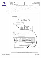
(1) 20-42-XX: Sleeves and Ferrules(Ref. Fig. 001)
NSA937493
NSA
CABLE GAUGE
12 10 8 6 4
001 001 001
001 002 - - -
- - -
CABLETYPE
AK AKBBE PDQD RD
SG
QF RF
14
001
TOPIC NUMBER
20-42-12
INDEX
NSA937493-XXX
(1) How to install a sleeve
You have to install a sleeve NSA937493on a CF type, gauge 14 cable
YOU MUST:- Define the sleeve P/N
- Select the applicable tool P/N
Sleeve NSA937493
Step 1:
Step 2:
Correlate the CABLE TYPE with the GAUGE in the table.
For cable type and gauge CF14, the sleeve P/N to be used is: NSA937493-001.
Note: In few cases, more than one reference may be applicable, thereforethe selection of the sleeves will be made according to the location,the temperature range or/and the color, as required.
Sleeve P/N tobe completed with the
suffix in the table
P/Nto make up the full
Shrink Sleeves - Allocation Table for cables
NSA937493 20 . 42 12.
CF
L_ES_000000_0_AAM0_01_01
Consult the cross reference tables (in: Manual Front Matter/indexes).
Figure 001 - How to Use - Example for Sleeves

Customer : GENType : ALLRev. Date : Apr 01, 2013
Manual : ESPMSelected applicability :
INTRODUCTION - DESCRIPTION AND OPERATION
Print date : April 24, 2013 Page 10 of 44
(Ref. Fig. 002)
NSA937493DIAMETER CODESTANDARD P/N
001
How to install a sleeve (Cont’d)
Step 3 :
Identify the tool P/N.
Sleeve P/N: NSA937493-001
(1)
20 . .42
SHRINKING TOOLINNER DIAMETER
(mm)DIAMETERCODE BEFORE
SHRINKINGAFTER
002
003
003
001 PR13
12E0178, and NSA937494NSA937493
For sleeve NSA937493-001 the shrinking tool to be used is 695-01-A4-433
Shrink Sleeves - P/N Characteristics and Shrinking Tools
or CV1981-42V-960W with shrinking head PR13.
SHRINKING
L_ES_000000_0_ACM0_01_01
NSA937493-XXX
NORM P/N
3.8(0.150)
0.5(0.019)
6.4(0.252)
1.5(0.059)
8.9(0.350)
3(0.118)
9.5(0.374)
4.5(0.177)
RAYCHEN695-01-A4-433
ORCV1981-42V-960W PR12
HEAD
Figure 002 - How to Use - Example for Sleeves

Customer : GENType : ALLRev. Date : Apr 01, 2013
Manual : ESPMSelected applicability :
INTRODUCTION - DESCRIPTION AND OPERATION
Print date : April 24, 2013 Page 11 of 44
(Ref. Fig. 003)
C. TYPE CV1981 HEAT GUNS THERE ARE FOUR GENERATORS OF THIS TYPE:
. .
SHRINKING TOOLS - HOT AIR GENERATOR REFLECTORS
PR12 TO PR2620 25 31
. .20 25 31
GENERATOR P/N
CV 1981-42V-960W
PR13SHRINK SLEEVES DIA 0 TO 6 mm
PR13CSOLDER SLEEVES (LONG LENGTH)
VARIOUS REFLECTORS ARE USED ACCORDING TO THE SLEEVE TO SHRINK:
PR12,
- Shrinking tool 20-25-31.
Where to find information about these tools?
Consult the cross reference table (Tool References index).
STEP 4:
, PR13C ETC.PR13
How to install a sleeve (Cont’d)(1)
CV1981-42V-960W WITH SHRINKING HEAD PR13 is descripted WDM chapter
L_ES_000000_0_AEM0_01_01
SUPPLY(V)
POWER(W)
SELECTORPOSITION
SWITCH0
SWITCH1
CV 1981-220V-1460W 220 1460
42 906
0 to 10 OFF ON
(0 TO 2.36 in)
Figure 003 - How to Use - Example for Sleeves
Customer : GENType : ALLRev. Date : Apr 01, 2013
Manual : ESPMSelected applicability :
INTRODUCTION - DESCRIPTION AND OPERATION
Print date : April 24, 2013 Page 12 of 44
The selection is done according to:- The type of terminal on which the sleeve is installed.- The type and gauge of the cable.
(2) 20-43-1X: Splices(Ref. Fig. 004)
Butt plices installed on the aircraft have the codes that follow:- ABS0249 Butt splice
- E0541 Butt Splice- NSA936803RA Hight temperature butt splice for copper cables- NSA936805RE Low temperature butt splice for copper cables.- NSA936807RB Butt splice for aluminum cables
ASN
E0360
Shrinking is done after crimping.
C. CONNECTION PROCEDURE (REF. FIG. 002)
(1) INSULATIONDO THE INSULATION WITH SHRINKABLE SLEEVES.
(1) TEMPERATURE
B. P/N CHARACTERISTICS
A. P/N IDENTIFICATION
E0360 - RK2220
Standard P/N
Reference No.
R = Splice CodeK = Type
2. E0360
1. General
20-43-11
NOTE : E0360 IS AN ASSEMBLY WHICH HAS:
- 1 SPLICE NSA936812.XX- 2 SLEEVES NSA937210MBXXXX
THREE TYPES OF BARRELS CAN BE AVAILABLE.THE INSTALLATION IS THE SAME.
Install these sleeves on the cables before stripping.
MINIMUM OPERATING TEMPERATURE IS -55 DEG.C (-67.00 DEG.F).MAXIMUM OPERATING TEMPERATURE IS 260 DEG.C (500.00 DEG.F).
22 = Sequence No.20 = Size Code
TOPIC NUMBER
(1) How to install a sleeve
Splice E0360
You have to install a splice E0360 on a high temperature cable, gauge 14
You must:- Define the splice P/N
- Select the appropriate tool P/N
.
Step 1:
Consult the cross reference tables (Manual Front Matter/index).
INDEX
Step 2:
Consult in text part the CHARACTERISTICS and the CONNECTION PROCEDURE .
20 . 43 11.
BUTT SPLICES - DESCRIPTION AND OPERATION
L_ES_000000_0_AFM0_01_01
- E0360RK Hight temperature butt splice
- NSA936813RH Butt splice for aluminium cables and for copper/aluminum cables.
Figure 004 - How to Use - Example for Splices

Customer : GENType : ALLRev. Date : Apr 01, 2013
Manual : ESPMSelected applicability :
INTRODUCTION - DESCRIPTION AND OPERATION
Print date : April 24, 2013 Page 13 of 44
(Ref. Fig. 005)
For splice E0360RK1614:- The length to be stripped is 5.8 mm with stripmaster tool 45-1939-1,- The shrinking tool to be used is CV1981-42V-960W with shrinking head PR13,- The crimping tool P/N is AMP 46469 Blue (in this case, there is no crimping head or die).
How to install a splice (cont’d)(2)
Step 3 :
Identify the full splice P/N with the wire gauge.
Splice P/N: E0360RK1614Identify the tool the P/N.
. .20 43 11
L_ES_000000_0_ALM0_01_01
BARREL TYPE 2
BARREL TYPE 3
CABLE
TYPESPLICE CODE
SIZE CODE
BARREL TYPE 1
NSA936812
SPLICE
NSA937210MB
SLEEVE 1
NSA937210MB
SLEEVE 2
R K 24 24EO360
E0360
SEQUENCE No.
A A
STANDARD P/N
CABLE
SPLICE WIREGAUGE
E0360RKXXXX
CRIMPING TOOLTOOL HEAD DIE
P/NNORMP/NNORMP/NNORM COLORHANDLE
69216
69217
AMP
AMP
69099
69099
AMP
AMP
YELLOW
WHITE
RED
BLUE
YELLOW
45730OR
0-069363-046467
46468
4646946470
69355
69064OR
69120OR
781019
69064OR
69120OR
781019
AMP
26-24
22-20
18-16
16-1412-10
8
6
RK2424
RK2220
RK1816
RK1614RK1210
RK0808
RK0606
-
-
-
-
-
-
-
-
5.8 (0.228)
1 2
SLEEVE
4 (0.157)
5 (0.197)
5.8 (0.228)
7.6 (0.299)
45-2020-1 BLUE
RAYCHEM
RK2424
RK2220
RK1816
RK1210
MB0130
MB0230
MB0340
MB0340
MB0340
MB0140
MB0240
MB0350
MB0350
MB0350
COLORP/NSPLICE LENGTH "A"
mm (in)
STRIPPING
TOOL
REDRK1614
NORMSTRIPMASTER
45-1939-1
MB0450 MB0450
NORM
CV1981-42V-960W+
HEAD PR13
E0360RKXXXX
CV1981-42V-960W+
HEAD PR13
Figure 005 - How to Use - Example for Splices

Customer : GENType : ALLRev. Date : Apr 01, 2013
Manual : ESPMSelected applicability :
INTRODUCTION - DESCRIPTION AND OPERATION
Print date : April 24, 2013 Page 14 of 44
(Ref. Fig. 006)
STRIPPINGDIES
CABLECLAMPING JAWS
DIES FOR THE TWOTYPES OF PLIERS AREDESIGNED FOR METRICSERIES CABLES
COLOREDHANDLES
STRIPPING TOOLS - STRIPMASTER
45-2020, 45-1939, 45-1773 AND 45-1774
HAND CRIMPING TOOLS - AMP
45730, 46467, 46468, 46469 AND 46470
(1) How to install a sleeve
Step 4 (cont’d)
- Stripmaster Stripping tool
Where to find information about these tools?Consult the cross reference tables (Tool/Reference index).
45-1939-1 is described in WDM chapter 20-25-11
. .20 25 31
- AMP Crimping tool 46469 is described in WDM chapter 20-25-22
. .20 25 22L_ES_000000_0_ANM0_01_01
Figure 006 - How to Use - Example for Splices

Customer : GENType : ALLRev. Date : Apr 01, 2013
Manual : ESPMSelected applicability :
INTRODUCTION - DESCRIPTION AND OPERATION
Print date : April 24, 2013 Page 15 of 44
(Ref. Fig. 007)
SHRINKING TOOLS - HOT AIR GENERATOR REFLECTORSPR12 TO PR26
GENERATOR P/N(V)
SUPPLY
CV 1981-220V-1460W
CV 1981-42V-960W
220ON
PR 13SHRINK SLEEVES DIA 0 TO 6 mm
VARIOUS REFLECTORS ARE USED ACCORDING TO THE SLEEVE TO SHRINK:PR12, PR13, PR13C ETC.
(2) How to install a splice (Cont’d)
Step 4 (Cont’d)
- Shrinking tool CV1981-42V-960W WITH SHRINKING HEAD PR13 is described in WDMchapter 20-25-31
. .20 25 31
. .20 25 31
L_ES_000000_0_APM0_01_01
(0 TO 2.39 in)
C. TYPE CV1981 HEAT GUNS THERE ARE FOUR GENERATORS OF THIS TYPE:
SUPPLY(V)
(W)POWER
POSITIONSELECTOR
0SWITCH
ISWITCH
OFF1460 0 to 10
90642
Figure 007 - How to Use - Example for Splices

Customer : GENType : ALLRev. Date : Apr 01, 2013
Manual : ESPMSelected applicability :
INTRODUCTION - DESCRIPTION AND OPERATION
Print date : April 24, 2013 Page 16 of 44
The selection is done according to the type of cable to which the splice is to be connected.Use the splice allocation table (Ref. 20-53-29) to select the splice for cable repair purposes.
NOTE: When splices are added on cables, we recommend to start a COC procedure to update therelated wiring diagram. (WDM)
(3) 20-44-XX: Connectors(Ref. Fig. 008)
(3) How to replace a contact on a connector
The following information is available:- The connector FIN is know from the AWM- The CABLE TYPE and GAUGE are known from the AWM- The connector P/N is retrieved via the FIN, from the AWL equipment listor from the IPC Additional Cross Reference Table or from the aircraft itself.
or from the aircraft itself.
"AWM: "
"AWL equipment list"
The connector installed on this equipment has the following P/N: E0052R14B19SNF
7K
7H
7J
AC
91-20-12
7C
7A
7B
AC
A
B
A
B382
PF28
1375 CF24
382PF28
91-20-12
FCSC-2BO 812VU
A
B
1374 CF2411CMT
11EMV
14DLD
2809VT121STA1380841VU
R
B388
1378 CF24
2603VC A801VU 121
STA1380
17
16
39
1377
B
C
J
B
B
18CE RATE GYRO UNIT122STA1020
388
1346
388
A
B
R
B
R
1205VC A915VU 120
STA1080
CF24
CF24
1018
101991-71-24
DC1
18YG
1207VT120STA1080915VU
CF241358
F3CE1 FCSC-1120STA1080 915VU 18CE
19
37
1243VG120STA1080915VU
CF24
38
18
A
.
L_ES_000000_0_ARM0_01_01
.
Figure 008 - How to Use - Example for Connectors

Customer : GENType : ALLRev. Date : Apr 01, 2013
Manual : ESPMSelected applicability :
INTRODUCTION - DESCRIPTION AND OPERATION
Print date : April 24, 2013 Page 17 of 44
(Ref. Fig. 009)
INDEX
20 . .
168
1621
TOPIC NUMBERASN
20-44-11E0052
20-44-11E0053
20-46-50E0048
44 11
CONTACT SIZENUMBER OF CONTACTS
1419
SHELL SIZECONTACT ARRANGEMENT
20 5#1616#20
19#20
AB
C
DE
FHJ
KL
M
N P
R
ST
U V
G
A
8#16
B
C
DE
F
G
H
A BC
D
E
FG
HJK
L
M
N
PR
S
TU
V
X
Y
(2) How to replace a contact on a connector (Cont’d)
YOU MUST:
- Define the contact P/N- Select the appropriate P/N for the:
. Insertion / Extraction tool. Crimping tool
Connector P/N: E0052R14B19SNF CF24
Step 1:
Step 2 :
Define the contact size.Correlate the connector P/N with the contact arrangement code.
Connector P/N: E0052R14B19SNF
Type NSA1599 Connectors - Contact Arrangements
ARS0497, E0052 and NSA938000 Plugs
For connector E0052R14B19SNF, the contact size is 20.
, cable type and gauge
Consult the cross reference tables (Manual Front Matter/index).
L_ES_000000_0_ATM0_01_01
Figure 009 - How to Use - Example for Connectors

Customer : GENType : ALLRev. Date : Apr 01, 2013
Manual : ESPMSelected applicability :
INTRODUCTION - DESCRIPTION AND OPERATION
Print date : April 24, 2013 Page 18 of 44
(Ref. Fig. 010)
20 . .44 11
ELEMENTS CONNECTION PROCEDURE XREF
NSA938151PXXXXXE0039
NSA938000
PLUGS
BY CONTACTS
BY COAXIALCONTACTS
NSA938171PL1600
NSA938172SL160020-48-33
E0052**
20-48-21
(2) How to replace a contact on a connector (Cont’d)
Step 3 :
Define the contact standard P/N.Correlate the connector P/N with the appropriate contact type in theconnection table which appears in the last page of the chapter.
Connector P/N:E0052R14B19SNF
S P
Type NAS1599 Connectors - Connection TableFigure 007
The contact standard P/N is NSA938152SXXXXX.Data related to this contact is contained in 20-48-21.
: Socket / : Pin
L_ES_000000_0_AVM0_01_00
NSA938152SXXXXX
Figure 010 - How to Use - Example for Connectors

Customer : GENType : ALLRev. Date : Apr 01, 2013
Manual : ESPMSelected applicability :
INTRODUCTION - DESCRIPTION AND OPERATION
Print date : April 24, 2013 Page 19 of 44
(Ref. Fig. 011)
PA1600 SA1600
PB2000RED RED
How to replace a contact on a connector (cont‘d)
Step 4:
20-48-21
CF2420
- Contact standard P/N:
- Cable type and gauge:
- Contact size:
NSA938152SXXXXX. (Socket type)
(2)
Define the complete contact P/N when you have the following information:
- Topic to consult:
PA1601PA1602
PA1200SA1202SA1200
BLUE
YELLOW
SB1600SC1600
SA1602SB1602SC1602
SA1601
ISO 8843
ISO 8843ISO 8843ISO 8843ISO 8843ISO 8843ISO 8843
MIL-C-39029/9MIL-C-39029/9
14 AND 1224 TO 18
24 TO 20
24 TO 18
REDRED
REDRED
BLUEBLUEBLUEBLUE
BLUE
YELLOWYELLOW
YELLOW
GREENGREEN
ORANGEVIOLET
VIOLET
BLACK
REDBROWN
18 TO 14
20 TO 16--
--
-
-
--
--
Normal Contacts - P/N Characteristics
NSA938151 AND NSA938152
SOCKET: NSA938152SXXXXX
.20 . 48 21
CONTACT
SOCKETPIN
SB2000
PA2000ORANGE
RED VIOLET
SPECIFICATION RING A RING B RING COR DOT
MIL-C-39029/9ISO 8843
COLOR IDENTIFICATIONADMISSIBLE
CABLE GAUGE
24 TO 18BROWN
YELLOWGREEN
ISO 8843 -
B: specific for Chromel cable type
C: specific for Alumel cable type
AContact P/N to be completed
with the suffix in the table
CONTACTSIZE
SA2000
: Copper alloy type (gold finish).
to make up the full P/N.
For connector E0052 with CF24 cable type and gauge, the complete contactP/N (Socket type) is NSA938152SA2000.
in the hook-up lists of the AWL. (entry point: Connector FIN)
Correlate the above information to select the appropriate contact suffix.
The steps 2, 3 & 4 are not necessary since the complete contact P/N is provided
.
.
.
-
L_ES_000000_0_AXM0_01_01
Figure 011 - How to Use - Example for Connectors

Customer : GENType : ALLRev. Date : Apr 01, 2013
Manual : ESPMSelected applicability :
INTRODUCTION - DESCRIPTION AND OPERATION
Print date : April 24, 2013 Page 20 of 44
(Ref. Fig. 012)
CONTACT
SOCKETPIN
SC2000
COLORP/N
INSERTION/EXTRACTION TOOLS
PC2000
PB2000 SB2000
WIRED MIL 81969/14-03 BLUE/WHITEMIL 81969/30-06 BLUE/SILVER
SOURIAU 8522-57 BLUECANNON CET 16-21 BLUE
DEUTSCH BLUEM15571+105911
UNWIREDSA1601PA1601PA1602 SA1602
SB1602SC1602
PA1600 SA1600SB1600SC1600
UNWIRED
MIL
DEUTSCH
81969/30-058522-56
M15571+105910
RED
REDRED
RED/SILVERRED/WHITE
SOURIAUCET 20-24CANNON
UNWIRED
MIL
DEUTSCH
81969/30-078522-58
M15571+105912
YELLOW
YELLOWYELLOW
YELLOW/SILVERWIRED MIL 81969/14-04 YELLOW/WHITE
SOURIAUCET 12-16CANNON
PA1200 SA1200
SA1202
CHARACTERISTICS NORM
--
--
-
SOCKET: NSA938152SXXXXX
.20 . 48 21
SA2000
(2) How to replace a contact on a connector (cont’d)
Step 5:
Define the insertion/extraction tool P/N when you have the following information:
- Contact P/N: NSA938152SA2000- Contact WIRED
Correlate the contact P/N and the applicable characteristics (wired in thepresent case) in the table to obtain the tool P/N.
Normal Contact - Insertion/Extraction Tools
for NSA938151 and NSA938152
For wired contact NSA938152SA2000 the Insertion/Extraction tool P/Nis MIL81969/14-02.
PA2000
,
,
L_ES_000000_0_AZM0_01_00
81969/14-02MILWIRED
Figure 012 - How to Use - Example for Connectors

Customer : GENType : ALLRev. Date : Apr 01, 2013
Manual : ESPMSelected applicability :
INTRODUCTION - DESCRIPTION AND OPERATION
Print date : April 24, 2013 Page 21 of 44
(Ref. Fig. 013)
2 x 24
COLOR
STRIPPING TOOL
BLUE
16 24 TO 14
LENGTHA mm (in)
24 TO 18 45-2020-1
CONTACTSIZE
20
NORMAL CONTACTS - STRIPPING CHARACTERISTICS AND TOOLS
NSA938151 AND NSA938152
NORM P/N
STRIPMASTER
STRIPPING CHARACTERISTICS
How to replace a contact on a connector (cont’d)(3)
Step 6 :
Define the stipping characteristics when you have the following information:
- Cable type and gauge:
- Contact size:
Correlate the above information in the table to obtain the stripping characteristics.
For CF24 cable type and gauge and contact size 20, the stripping length is4.5 mm with stripmaster tool 45-20201.
CABLE
GAUGE
L_ES_000000_0_BAM0_01_01
CF24.
4.8
7
4.5
(0.189)
(0.275)
(0.177)
Figure 013 - How to Use - Example for Connectors

Customer : GENType : ALLRev. Date : Apr 01, 2013
Manual : ESPMSelected applicability :
INTRODUCTION - DESCRIPTION AND OPERATION
Print date : April 24, 2013 Page 22 of 44
(Ref. Fig. 014)
20 .
CONTACTSIZE
CABLEGAUGE
16 12
22 20 18 24 22 20 18 16 14 24 22 20 18 16 14 12
PIN
SO
CK
ET
PA
2000
PA
2000
PB
2000
PC
2000
PA
2000
PB
2000
PC
2000
PA
2000
PL1
600
PA
1600
PA
1600
PA
1600
PA
1600
PA
1602
PA
1602
PA
1600
PA
1602
PA
1601
PA
1602
PA
1601
PA
1601
PA
1200
PA
1200
PA
1200
PA
1200
PA
1200
SA
2000
SB
2000
SC
2000
SA
2000
SB
2000
SC
2000
SA
2000
SL1
600
SA
1600
SA
1602
SA
1602
SA
1602
SA
1602
SA
1600
SA
1600
SA
1600
SA
1600
SA
1601
SA
1601
SA
1601
SA
1202
SA
1202
SA
1202
SA
1202
SA
1200
SA
1200
SA
1200
SA
1200
SA
1200
SJ
TK
UD
BF
PF
QF
RF
SF
TJ
UK
BE
SG
PD
QD
DK
ST
TT
UE
PG
RD
DE
SE
TG
UG
PE
QE
RE
AA
AA
AA
AA
AA
AA
AA
A
AA
AA
AA
AA
AA
AA
AA
A
AA
AA
AA
AA
AA
AA
AA
AA
AA
AA
AA
AA
AA
AA
AA
AA
AA
AA
AA
AA
AA
A
AA
AA
AA
AA
AA
AA
A
AA
AA
AA
AA
AA
AA
A
AA
AA
A
AA
AA
AA
AA
A
AA
AA
AA
AA
AA
AA
A
AA
AA
A
AA
A
AA
AA
A
AA
AA
A
AA
A
AA
AA
A
BB
BB
BB
BB
BB
BB
B
BB
BB
BB
BB
BB
BB
BB
B
DD
DD
DD
D
DD
DD
DD
DD
DD
DD
DD
DD
DD
DD
DD
DD
DD
DD
DD
DD
DD
DD
DD
DD
DD
DD
DD
DD
AA
AA
AA
AA
AA
AA
AA
AA
AA
AA
AA
AA
AA
AA
A
CC
CC
CC
CC
CC
CC
CC
CC
CC
CC
CC
CC
CC
CC
CC
C
CC
CC
CC
CC
QG
RH
AA
A
- - - -
AK
21.48NORMAL CONTACTS - SLEEVE ALLOCATION
NSA938151 AND NSA938152
How to replace a contact on a connector (cont’d)(3)
Step 7:
Define the sleeve allocation when you have the following information:
- Contact P/N : NSA938152SA2000- Cable type and gauge : CF24- Contact size : 20
Correlate the above information in the table to obtain the sleeve allocation.
.
..
24
20
ASA
2000
CF
L_ES_000000_0_BCM0_01_01
FO
R L
EG
EN
D ,
SE
E F
IGU
RE
ON
SLE
EV
E S
HR
INK
ING
CH
AR
AC
TE
RIS
TIC
S.
CA
BLE
TY
PE
(SE
E O
N N
EX
T IL
LUS
TR
AT
ION
)
Figure 014 - How to Use - Example for Connectors

Customer : GENType : ALLRev. Date : Apr 01, 2013
Manual : ESPMSelected applicability :
INTRODUCTION - DESCRIPTION AND OPERATION
Print date : April 24, 2013 Page 23 of 44
(Ref. Fig. 015)
20 . 21.48
A: PIN AND SOCKET INSTALLED WITHOUT SLEEVE
1 DOUBLE OVER THE CONDUCTOR OF THE GAUGE # 24 AND # 22 CABLES IN THE GAUGE # 16 CONTACTS
1
1
C: USE E0718-01 SLEEVE OR A NSA937210MB02 SLEEVE AND
B: USE E0718-20 SLEEVE OR A NSA937210MB01 SLEEVE AND
DOUBLE OVER THE CONDUCTOR OF THE GAUGE # 16, 18 AND # 20 CABLES IN THE GAUGE # 12 CONTACTS
D: IF SEALING IS NECESSARY, USE ONE OR SEVERAL HEAT-SHRINKABLESLEEVES. SEE THE TABLE BELOW
FOR THE NSA937210MB01 AND MB02 SLEEVES, USE THE TOOL CV1981-42V-960W WITH THE HEAD PR13. FOR DETAILS, SEE FIGURE ON SLEEVES ALLOCATION.
CABLE CAVITYSIZE
TYPE GAUGE 20 16 12 20-XX 01-XX 023-XX
SHRINKABLE SLEEVEE0718-XX-XX
SHRINKING TOOL
20
18
24
22
20
18
16
24WF
CF
2
1
1
1
2
2
1
1
1
1
2
X
X
X
X
X
X
X
X
X
X
X
NORMAL CONTACTS - SLEEVE SHRINKINGNSA938151 AND NSA938152
+
NORM P/N
RAYCHEM CV1981-42V-960W+HEAD PR13
How to replace a contact on a connector (cont’d)(3)
For cable CF24, socket type SA2000, size 20, the code is
It corresponds to a contact installed without sleeve.
Step 7 (cont’d):
A:
L_ES_000000_0_BEM0_01_01
Figure 015 - How to Use - Example for Connectors

Customer : GENType : ALLRev. Date : Apr 01, 2013
Manual : ESPMSelected applicability :
INTRODUCTION - DESCRIPTION AND OPERATION
Print date : April 24, 2013 Page 24 of 44
(Ref. Fig. 016)
SOCKET: NSA938152SXXXXXPIN: NSA938151PXXXXX
CONTACT WIREGAUGE
P/N
HAND CRIMPING TOOL
P/N
BLUE
65
2
54
2 x 24
PB2000
SB2000PC2000SC2000
* ONLY FOR CONTACTS NSA935151PAXXXX OR NSA938152SAXXXX
22520/2-0122520/7-01
22520/2-0222520/7-02
NORM NORM
SELECTORPOSITIONCOLOR
TOOL TURRET/LOCATOR
-
-
PA2000
How to replace a contact on a connector (cont’d)
Step 8:
Define the crimping tool P/N when you have the following information:
- Contact P/N: NSA938152A2000- Cable gauge: 24
Correlate the contact P/N and the cable gauge in the table
For contact P/N NSA938152SA2000 with cable gauge 24, the crimping tool is:M22520/2-01 with turret M22520/1-02 selector position 2.Or M22520/2-01 with turret M22520/2-02 selector position 5.Or M22520/7-01 with turret M22520/7-02 selector position 4.
(2)
22520/7-01 22520/7-02
.
.
to obtain the crimping tool P/N.
24
. .20 48 21
Normal Contact - Crimping ToolsFor NSA9358151 And NSA938152
SA200022520/1-01
22520/2-01
22520/1-02
22520/2-02
22520/7-01 22520/7-0222
22520/1-01
22520/2-01
22520/1-02
22520/2-02
3
65
22520/7-01 22520/7-0220
22520/1-01
22520/2-01
22520/1-02
22520/2-02
4
76
22520/7-01 22520/7-0218 *
22520/1-01
22520/2-01
22520/1-02
22520/2-02
5
87
-
-
-
22520/1-02 4
22520/7-01 22520/7-0320
22520/2-016-57
18 *22520/1-0122520/7-01
22520/2-0222520/7-03 -
BLUE
SC1602
14 22520/1-01 22520/2-02
6
78
YELLOW
16
12
PA1200SA1200
2222520/1-01 22520/2-02
2
34
YELLOW
24
20518
SA1202
L_ES_000000_0_BGM0_01_01
Figure 016 - How to Use - Example for Connectors

Customer : GENType : ALLRev. Date : Apr 01, 2013
Manual : ESPMSelected applicability :
INTRODUCTION - DESCRIPTION AND OPERATION
Print date : April 24, 2013 Page 25 of 44
(Ref. Fig. 017)
STRIPPINGDIES
CABLECLAMPING JAWS
COLOREDHANDLES
20 .
STRIPPING TOOLS - STRIPMASTER
.25 11
20 . .25 22
HAND CRIMPING TOOL - DANIELS
M22520/2-01
How to replace a contact on a connector (cont’d)(3)
45
67
81
23
PUSHPOSITIO
NERAND
ROTATE90°TO
INSTALI
SELECTOR KNOB
LOCKING RING
HOLE FOR LOCKINGCLIP
45-2020, 45-1939, 45-1773 AND 45-1774
Where to find information about these tools?
- Stripmaster stripping tool
Consult the cross reference table (Tool Reference index).
Step 9:
- Mil crimping tools
45-2020-1 is described in WDM chapter 20-25-11
M22520/2-01 OR M22520/7-01 are described in the WDM Chapter 20-25-22
L_ES_000000_0_BJM0_01_01
Figure 017 - How to Use - Example for Connectors

Customer : GENType : ALLRev. Date : Apr 01, 2013
Manual : ESPMSelected applicability :
INTRODUCTION - DESCRIPTION AND OPERATION
Print date : April 24, 2013 Page 26 of 44
(Ref. Fig. 018)
20 . .25
How to replace a contact on a connector (cont’d)(3)
41M81969/14
Step 9 (cont’d)
M81969/14-02COLOR: WHITE/RED *
SIZE: 20
INSERTION/EXTRACTION TOOLS - EXAMPLES OF TOOLS
Insertion/extraction tool MIL81969/14-02 is described in ESPM Chapter 20-25-41
L_ES_000000_0_BLM0_01_00
Figure 018 - How to Use - Example for Connectors

Customer : GENType : ALLRev. Date : Apr 01, 2013
Manual : ESPMSelected applicability :
INTRODUCTION - DESCRIPTION AND OPERATION
Print date : April 24, 2013 Page 27 of 44
The search for connectors generally comes from the need to repair, replace or install a connector.Therefore, at least the FIN is known and you can retrieve the related P/N with the help of the IPC orAWL.This chapter helps the user define the characteristics of the required connector, its contacts and therelated connection procedure.
(a) In Aircraft On Ground (AOG) situationIf a spare connector is not available, it can be possible to temporarily use the unused cavities ofthe damaged connector if AIRBUS agrees.You must contact AIRBUS to get a written agreement to use the unused cavities.AIRBUS will make an analysis of:- Compliance with the applicable electrical segregation rules.- The condition of the connector and type of damage.- The general environnement of the connector.- The status of the unused cavities of the specific aircraft. (There is no EO or STC that
uses these cavities) If you think that the damage can have an effect on the integrity of theconnector, you must not use the unused cavities. This modification of the connector writingmust have the agreement of AIRBUS and can only be temporary. AIRBUS will specify thelimitation time for each change.
(4) 20-44-5X: Terminal Blocks(Ref. Fig. 019)
(4) How to install a terminal lug on a terminal block
The following information is available:- The terminal block FIN is know from the AWM-CABLE TYPEand GAUGE are known from the AWM- The terminal block P/N is retrieved via the FIN from the AWL equipment list
or from the IPC Additional Cross Reference Table.
"AWM: "
"AWL equipment list"
The cable type and gauge cf 10 is connected to the terminal block P/N: NSA937905A10.
ELEC PWRDC DISTRIBUTION305PP ESS BUS 28VDC
24. .18
NOTE : UNLESS OTHERWISE SPECIFIED PREFIX ALL WIRE IDENTIFICATION WITH ATA 2459
UNLESS OTHERWISE SPECIFIED ALL ROUTES ARE 4P
1 2
1 2
1 2
1 2
1 2
1086
1176
LOCEQPTDES DESCRIPTION REF TO
CH-SE SC W
27-12
32-61
01
02
01
01
32-42 03 02
3CG V63 FLT CTL AIL TRIM
3GB U53
SYS 1 FLT/GND119GB U52
DN/CTR PNL POS INDHYD-L/G PROX DET/RELAY SYS 1 GEAR
HYDRAULIC-L/G PROX DET AND RELAYS
HYDRAULIC-L/G SYS 1 RELAYS AND
STRG
1 2
5
6
1
22
11
1
305PP28VDCESS BUS
24-55-01(24-55 SCH2)
G2
1 2
1 2
1000
10002ES Q72 ENGINES-OIL ENG 2 LO PRESS
1 2
1 2 SLATS SYS 19CV R66
1043PP
FLT CTL-SFCC LAND RECOVFLAPS SYS 1
R67 FLT CTL-SFCC10CV
1KG
133VU REAR CIRCUIT BREAKER PANEL1041PP
10872QF
4WF
2WF
7WF
A63
A62
A61
A60
APU-FUEL LP VALVE SUPPLY
APU-FUEL LP VALVE CTL
APU-FIRE EXTING-SQUIB B
APU-FIRE EXTING-SQUIB TEST
APU-FIRE DET LOOP B
131VU REAR CIRCUIT BREAKER PANEL
120VU REAR PANEL
32-6132-6232-6132-6232-51
02
0201
01
03
01
212STA995
49-30 0249-33 01
26-22 01 01
26-22 01 04
26-22 01 01
26-13 01 01
49-60 0149-61 01
59
UNLESS OTHERWISE SPECIFIED ALL WIRES ARE CF10 GAUGE
180VT
.
.
L_ES_000000_0_BNM0_01_01
Figure 019 - How to Use - Example for Terminal Blocks

Customer : GENType : ALLRev. Date : Apr 01, 2013
Manual : ESPMSelected applicability :
INTRODUCTION - DESCRIPTION AND OPERATION
Print date : April 24, 2013 Page 28 of 44
(Ref. Fig. 020)
20-48-12
TYPE ATA REFCONNECTION TYPE CONNECTION P/N
CONNECTION BY TERMINALS
20-48-12
ELEMENTP/N
E0421
MAINTENANCE PROCEDURE XREF
NSA936504TCNSA936507TG
TOPIC NUMBERNSA
20 . .44 52
20-44-52NSA93790420-44-52NSA93790520-44-52NSA93790620-48-20NSA937910
20-48-11NSA936501TA
E0647
E0422TR-E0466TS
E0422TR-E0466TS
TERMINALS MUST BE SELECTED DEPENDING ON CABLE AND AIRCRAFT TYPE:- FOR YV CABLE: ON A330/A340 USE ASNE0422TRXXXX
ON A319/320/321 USE ASNE0466TSXXXX
- FOR Y AND YU CABLES: GAUGE 0000 USE ASNE0223TLXXXX
- FOR DG CABLE: GAUGE 26 TO 10 USE NSA936501TAXXXXGAUGE 8 TO 0000 USE NSA936507TGXXXX
CONNECTION TABLENSA936507TG REPLACES NSA936504TC
NSA937905
INDEX
CAUTION:
NOTE:
(4) How to install a terminal lug on a terminal block (cont’d)
Terminal block P/N , cable type and gauge CF10NSA937905A10Step 1:
Find the terminal block P/N in the connection table to define the terminal lug P/N.
Step 2:
For terminal block P/N NSA937905, the connection P/N is NSA936501 or NSA936504TC or NSA936507TG.Data related to this terminal lug is contained in 20-48-11
YOU MUST:
- Define the terminal lug P/N
- Select the applicable tool P/N
Consult the cross reference tables (Manual Front Matter/indexes).
L_ES_000000_0_BPM0_01_01
Figure 020 - How to Use - Example for Terminal Blocks

Customer : GENType : ALLRev. Date : Apr 01, 2013
Manual : ESPMSelected applicability :
INTRODUCTION - DESCRIPTION AND OPERATION
Print date : April 24, 2013 Page 29 of 44
(Ref. Fig. 021)
7.9
NSA936501TAXXXX
20 . .
Stratotherm Terminals for Copper Cables - Allocation table
48 11
20-48-11NSA936501
CF10
- Topic to be consulted
-Terminal lug P/N:
INSULATINGCOLORED SLEEVE
CABLE
TERMINALUS mm
TA2201
24
TA1407TA1001 2.8#4TA1002 3.5#6TA1003 4.2#8
ANDTA1005 12 6.31/4TA1006 7.95/16TA1007 9.53/8
BLACK
STANDARD P/N
NSA936501
RANGECABLE GAUGETYPE CODE
SLEEVECOLOR
TA2202TA2203
3/85/16
9.5
#4 2.8#6 3.5
CABLEGAUGE
#10 4.8TA1004
STUD DIA B
- Cable type and gauge:
TERMINAL DIMENSIONB
NSA936501
Correlate the terminal standard P/N with the stud diameter and cable gauge to define the complete terminal lug P/N.
The completel terminal lug P/N to be fitted on a cable gauge 10,on a 4.8 mm DIA terminal stud is: NSA936501TA1004.
Define the complete terminal lug P/N, when you have the following information:
Terminal lug P/N to
suffix in the tableto make up the full
P/N.
be completed with the
10
A
.
TA 22 05
(4) How to install a terminal lug on a terminal block (cont’d)
..
L_ES_000000_0_BRM0_01_01
Step 3:
Figure 021 - How to Use - Example for Terminal Blocks

Customer : GENType : ALLRev. Date : Apr 01, 2013
Manual : ESPMSelected applicability :
INTRODUCTION - DESCRIPTION AND OPERATION
Print date : April 24, 2013 Page 30 of 44
(Ref. Fig. 022)
NSA936501TA1004.
Define the tooling data when you have the following information:
- Cable type and gauge:
- Terminal lug P/N
Correlate the above information in the table to obtain the tool P/N.
Stratotherm Terminals for Copper Wires - Tools
for
For terminal lug P/N NSA936501TA1004 the crimping tool P/N is:AMP 69710 with one dot on the die.
The stripping tool is:STRIPMASTER 45-1939-1 (RED)
TERMINAL
COLOR
TERMINAL
P/N
BLUE45-2020-1
TA22XX
TA20XX
TA16XX
TA14XX
COLOR
DOTDIE
P/N
TA22XX
734535-1
OR
576784
69735 BLACK
NSA936501TAXXXX
STRIPPING
WIREGAUGE TOOL
24
22
20
18
16
2 X 18
14
12
2 X 14
12
6
9
6
2 X 14OR
CABLEGAUGE
BROWN
BLACK
69710
576778
69710
NORM
-
-
-
-
P/N COLOR
DIEP/N
576711 BROWN
69735 BLACK
NORM
-
-
-
-
PNEUMATIC TOOL
-
-
-
-
-
-
-
-
-
-
69365
69365
69365
-
-
-
-
AMP
AMP
AMP
24
BLACK/BROWN
GREY/BROWN
BLACK/BLACK
CRIMPING TOOLS
HAND TOOLS
-
-
-
TERMINALSLEEVECOLOR
20 . .48 11
RED45-1939-1TA10XX
LENGTH "A"(mm) – 0.3
STRIPMASTER
P/NNORM
HANDLECOLOR
NSA936501
CF10.
(3) How to install a terminal lug on a terminal block (Cont’d)
Step 4
910
L_ES_000000_0_BTM0_01_01
OR22
576711 BROWN
-- -
2 X 16 AMP
NSA936501TAXXXX
576723
69735BLACK OR
576723
69375BLACK10
69694-1 BLACK2 X 14
TA10XXOR
6971010
Figure 022 - How to Use - Example for Terminal Blocks

Customer : GENType : ALLRev. Date : Apr 01, 2013
Manual : ESPMSelected applicability :
INTRODUCTION - DESCRIPTION AND OPERATION
Print date : April 24, 2013 Page 31 of 44
(Ref. Fig. 023)
DIES FOR THE TWOTYPES OF PLIERS AREDESIGNED FOR METRICSERIES WIRES
STRIPPINGDIES
CABLECLAMPING JAWS
COLOREDHANDLES
20 .
20 .
STRIPPING TOOLS - STRIPMASTER
.25 11
.25 22
HAND CRIMPING TOOLS - AMP
69710
45-2020,45-1939,45-1773 AND 45-1774
(4) How to install a terminal lug on a terminal block (Cont’d)
Step 5:
Stripmaster Stripping tool
Where to find information about these tools?Consult the cross reference tables (miscellaneous P/N index).
45-1939-1 is described in ESPM chapter 20-25-11
NOTE: If several lugs are installed on a simple stud, see the chapterdescribing terminal stacking.
- AMP Crimping tools 69710 are described in ESPM chapter 20-25-22
L_ES_000000_0_BVM0_01_01
Figure 023 - How to Use - Example for Terminal Blocks
Customer : GENType : ALLRev. Date : Apr 01, 2013
Manual : ESPMSelected applicability :
INTRODUCTION - DESCRIPTION AND OPERATION
Print date : April 24, 2013 Page 32 of 44
For the selection of terminal block P/Ns, do as for the connectors, but you must do the allocation ofterminals in relation to the type of cable and the type of equipment, and obey, in addition, the terminalstacking rules. (Ref. 20-51-40)
(5) 20-46-5X: Relays and Relay Bases(Ref. Fig. 024)
CONNECTION BY RELAY BASE
P/N TYPE ATA REF.
CONNECTIONNSA932801 NSA932805
CONNECTION
CONNECTION
CONNECTION
CONNECTION
NSA932803
NSA932807
NSA932805
NSA932815
RELAY
CONNECTION TYPE RELAY BASE P/N
-
MAINTENANCE PROCEDURE XREF
BY RELAY BASE
BY RELAY BASE
NO RELAY BASE
NSA932810
INDEX
20 .
TOPIC NUMBER
You must:
NSA
NSA932804NSA932805NSA932806
. 50
- define the connection P/N
RELAYS/RELAY BASES - ALLOCATION TABLE
46
20-46-50
20-46-50
20-46-50
20-46-50
20-46-50
20-46-50
20-46-5020-46-5020-46-50
Consult the cross reference tables.
(5) How to install relays
NSA932804 NSA932806You have to install two relays .
Relays
Step 1:
Step 2:
Define the connection type:
Find the RELAY P/N’s in the table to get the corresponding relay base P/N’S
For relay NSA932806, there is no relay base.For relay NSA932804, the relay base is NSA932805.
and
NSA932804 NSA932806 .and
BY RELAY BASE NSA932805NO RELAY BASE -NSA932806
NSA932804
L_ES_000000_0_BXM0_01_00
Figure 024 - How to Use - Example for Relays

Customer : GENType : ALLRev. Date : Apr 01, 2013
Manual : ESPMSelected applicability :
INTRODUCTION - DESCRIPTION AND OPERATION
Print date : April 24, 2013 Page 33 of 44
(Ref. Fig. 025)
Define the connection/contact arrangements
STEP 3:
The contact/connection arrangement can be used to identifyNOTE:
POLARIZATIONPIN
POLARIZATIONPIN
NSA932805NSA932805
RELAY BASES - CONTACT ARRANGEMENTS
E0673, E0745, E0746, NSA932805 NSA932815 AND NSA932816
RELAYS - CONNECTION ARRANGEMENTS
NSA932806 AND NSA932807
20 46 50
How to install relays (cont’d)(5)
NSA932805 NSA932806
20 46 50
The exact location of the concerned connection point.
and
NSA932806
L_ES_000000_0_BZM0_01_00
Figure 025 - How to Use - Example for Relays

Customer : GENType : ALLRev. Date : Apr 01, 2013
Manual : ESPMSelected applicability :
INTRODUCTION - DESCRIPTION AND OPERATION
Print date : April 24, 2013 Page 34 of 44
(Ref. Fig. 026)
NSA932807NSA932819NSA932820
TYPE ATA REF.
CONNECTION
CONNECTION
CONNECTION
CONNECTION
CONNECTION
CONNECTION
CONNECTION
BY CONTACTS
BY CONTACTS
BY CONTACTS
BY CONTACTS
SEALING
SEALING
SEALING
SEALING
BY CONTACTS
BY DUMMY CONTACTS
CONNECTION
CONNECTION
CONNECTION
CONNECTION
CONNECTION
E0078
E0078
NSA932833DB1600
NSA938153BA1600
NSA932829DA1600
NSA938188
NSA932829DA1200
NSA938153BA1600
NSA938153BA1200
NSA932833DB1600
NSA932833DB1601
NSA938153
NSA932815
NSA932816
NSA932818
NSA932823
NSA932825
NSA932827
NSA932833
NSA932838
NSA932844
NSA932847
SOLDERED
SOLDERED
SOLDERED
SOLDERED
SOLDERED
SOLDERED
20-48-25
20-48-25
20-48-41
20-48-25
20-48-25
20-48-41
20-48-41
20-48-25
20-48-25
20-48-25
20-48-25
20-48-23
20-48-41
- -
- -
- -
- -
- -
- -
RELAY BASEP/N CONNECTION TYPE CONNECTION P/N
BLANKING PLUG
BLANKING PLUG
BLANKING PLUG
TYPE ATA REF.CONNECTION TYPE CONNECTION P/N
CONNECTION 20-48-11
RELAYP/N
NSA932829
MAINTENANCE PROCEDURE XREF
MAINTENANCE PROCEDURE XREF
RELAYS AND RELAY BASES - CONNECTION TABLE
20 . .46 50
(5) How to install relays (cont’d)
Step 4
- Relay base P/N:
Define the connection P/N:Correlate the relay/relay base P/N with the appropriate contact type
NSA932805
In the connection table wich appears on the last page of the page of the chapter.
- Relay P/N: NSA932806
For relay NSA932805, the contact P/N to be used is: E0078.Data related to this contact is contained in 20-48-25.For relay NSA932806, the contact P/N to be used is: NSA936501Data related to this terminal is contained in 20-48-11.
NSA932805
NSA932806
BY CONTACTS E0078
L_ES_000000_0_CAM0_01_00
BY TERMINALS NSA936501
Figure 026 - How to Use - Example for Relays

Customer : GENType : ALLRev. Date : Apr 01, 2013
Manual : ESPMSelected applicability :
INTRODUCTION - DESCRIPTION AND OPERATION
Print date : April 24, 2013 Page 35 of 44
For the selection of relay P/Ns, do as for the connectors. The only difference is to know if the relay isconnected with or without a relay base.
(6) 20-53-XX: Repair Processes(Ref. Fig. 027)
(Ref. 20-53-54)
TOPIC NUMBER
E0261 23-53-21
REPAIR BackshellsBraided Conduits
EFCS and Sensitive Cables
Electrical Components and Grounding Modules
Fire-Resistant CablesGeneral Processes for cablesHeat shrinkable conduitsMetallic Conduits
Normal ContactsOptical Fiber CablesRaceway AssembliesScreened CablesSplices
Feeder Cables
INDEX
INDEX
You must:- Select the appropriate repair procedure
- Define the standard item P/Nnecessary for the repair.
Step 1:
Electrical Cables
Consult the cross reference table index.
ASN
(6) How to repair a cable
Define the cable or its P/N to repair:
ELECTRICAL STANDARD CABLE, E0261CFYou have to repair an . Gauge 14 cable.
Consult the alphabetical index.
or
Cable P/N E0261
The repair processes for electrical cable are in the chapter 20-53-20.L_ES_000000_0_CCM0_01_01
Bundle Protections - GeneralCableCable Supports
Bundle Attachments - General
(Ref. 20-53-45)(Ref. 20-53-32)(Ref. 20-53-40)(Ref. 20-53-30)(Ref. 20-53-20)(Ref. 20-53-41)(Ref. 20-53-41)
(Ref. 20-53-41)
Standard Cables
Standard Electrical Items
(Ref. 20-53-27)
(Ref. 20-53-25)(Ref. 20-53-26)(Ref. 20-53-29)(Ref. 20-53-34)(Ref. 20-53-32)
(Ref. 20-53-55)(Ref. 20-53-28)(Ref. 20-53-43)(Ref. 20-53-22)(Ref. 20-53-53)
(Ref. 20-53-50)
Miscellaneous conduits (Ref. 20-53-33)
(Ref. 20-53-20)
(Ref. 20-53-21)
Figure 027 - How to Use - Example for Repair

Customer : GENType : ALLRev. Date : Apr 01, 2013
Manual : ESPMSelected applicability :
INTRODUCTION - DESCRIPTION AND OPERATION
Print date : April 24, 2013 Page 36 of 44
(Ref. Fig. 028)
the WDM. (AWM/ASM/AWL).
ELECTRICAL CABLE REPAIR PROCESSES - DESCRIPTION AND OPERATION
When a cable is damaged or broken, the standard procedure is to replace it with a cable that has the same P/N.
.20 . 53 20
(6) How to repair a cable (cont’d)
Step 2:
20-53-20: Electrical cable repair processes.Consult this chapter for general information.Correlate the cable type with the apropriate sub chapter.
1. General
NOTE:
L_ES_000000_0_CFM0_01_01
MAKE SURE THAT NO AC OR DC POWER SOURCE IS CONNECTED TO THE AIRCRAFT
ELECTRICAL CIRCUITS.
THERE IS A RISK OF ELECTROCUTION IF THE AC OR DC POWER STAYS CONNECTED.
DO NOT USE THESE PROCESSES FOR THE CABLES IN HARNESSES IDENTIFIED BY A PART
NUMBER (CABLES FOR ENGINES, LANDING GEAR, FUEL TANKS, APU, ETC., BUT NOT FOR THE
A380 PEPDC OR SEPDC’S). REFER TO THE RELATED VENDOR (OR MANUFACTURER’S)
DOCUMENTATION.
WARNING:
CAUTION:
If applicable, the cable type for repair could be either the cable drawing type (CF, DK, DM) or the new DRIF APPLICABLE, THE CABLE TYPE FOR REPAIR could be either the part (refer to chapter 20-32-21)
2. Terminology
Conductor:
3. Repair steps
When a standard electrical item is damaged, do these steps:- Find the damaged cable and its identification. (P/N, type, sensitive/EFCS)- Find and correct the cause(s) of the damage.
4. Structure of the Chapters
- Repair of Standard Cables (Ref. 20-53-21)- Repair of Screened Cables Ref. 20-53-22)- Repair of Coaxial and Quad Cables (Ref. 20-53-23)- Repair of Thermocouple Cables (Ref. 20-53-24)- Repair of Aluminum Cables (Ref. 20-53-25)- Repair of Fire-Resistant Cables (Ref. 20-53-26)- Repair of EFCS and Sensitive Cables (Ref. 20-53-27)- Repair of Optical Fiber Cables (Ref. 20-53-28)- General Repair Procedure (Ref. 20-53-29)
The conductor is conducting element of the cable formed from one or more strands.
The chapters that rorrow give for repair could be either
The repair processes for E0261CF standard cable are in the chapter 20-53-21.
Figure 028 - How to Use - Example for Repair

Customer : GENType : ALLRev. Date : Apr 01, 2013
Manual : ESPMSelected applicability :
INTRODUCTION - DESCRIPTION AND OPERATION
Print date : April 24, 2013 Page 37 of 44
(Ref. Fig. 029)
Step 3:
20-53-21: Repair of standard cable.
Cable P/N:
REPAIR OF STANDARD CABLES - DESCRIPTION AND OPERATION
(6) How to repair a cable (cont’d)
Consult this chapter to define the appropriate repair procedure.
E0261CF
20 . 53 . 21
This chapter gives the technical requirements for repair of the single-coreAnd multi-core unscreened cables:
- Single-Core Cables for Panels Boxes, Low-Temperature 200 deg.C (392.00 deg.F)These cables found only in panels or in boxes have P/Ns:E0260 BFNSA935041 BE
- Single-Core or Multi-Core Cables, Unscreened, Low-Temperature 200 deg.C
These cables installed on aircraft have P/Ns:E0261 or EN2266-003A CF, E0261 or EN2266-004A CF-C, E0261 or EN2266-005ACF-UE0264 or EN2266-003B PFE0266 or EN2266-003C QFE0268 or EN2266-003D RF
(392.00 deg.F)
A. Single-Core Cables for Panels and Boxes, Low-Temperature 200 deg.C(392.00 deg.F)(1) Cable layout(Ref. Fig. 001)(2) Table for damage assessment(Ref. Fig. 001)
(1) Cable layout(Ref. Fig. 002)(2) Table for damage assessment(Ref. Fig. 002)(3) When the repair type is selected, refer to:(a) Para. 3 Repair Procedure for the general description and conditions of application.(b) 20-53-29 GENERAL REPAIR PROCEDURE for more data.
B. Single-Core or multi-Core Cables, Unscreened, Low-Temperature 200 deg.C(392.00 deg.F)
1. GENERAL
2. DAMAGE CHECK PROCEDURE:
L_ES_000000_0_CJM0_01_01
Figure 029 - How to Use - Example for Repair

Customer : GENType : ALLRev. Date : Apr 01, 2013
Manual : ESPMSelected applicability :
INTRODUCTION - DESCRIPTION AND OPERATION
Print date : April 24, 2013 Page 38 of 44
(Ref. Fig. 030)
YOU CAN SEE POLYIMIDE INSULATION BUT
TYPE: AKA, AKB, , CF-C, CF-U, PD, QD, RD, RF, AK(150°C/302°F)
.20 . 53 21
DAMAGE LOCATION DAMAGE ASSESSMENT GRADE REPAIR SCHEME
** IN SOME CASES, THE COATING CAN HAVE A DIFFERENT COLOR
COATING: - SURFACE SCRATCHES - OUTER COATING
LOW TEMPERATURE CABLES -
AK, , PD, PF, QD, QF, RD AND RF
(ORDER OF PRIORITY)
LAYOUT AND TABLE OF DAMAGE CASES
(6) How to repair (cont’d)
Step 3 (cont’d):
Define the appropriate repair procedure:
- Make an accurante estimate of the type of damage.For example:
- Refer to the table of damage cases.Deep Nicks on Insulation
CF14
Depending on the length of the damage, the repair scheme is 1-C, 1-D or 1-ERefer to the para repair procedure.
.
CF
Cable type:
L_ES_000000_0_CMM0_01_01
INSULATION:
POLYMIDE TAPESAMBER COLOR
COATING:
SINGLE: WHITE **OR DOUBLE (ONLY CF-C)
DARK + WHITE **
CONDUCTOR:
Cu Ni OR Cu Ni ALLOYACCORDING TO GAUGE
METAL COLOR
1 *
1 1-B
BUT THE COATING IS NOT DAMAGED
YOU CAN SEE THE CONDUCTOR BUT- DEEP NICKS IN POLYIMIDE:
IT IS NOT DAMAGED.
INSULATION:YOU CANNOT SEE THE CONDUCTOR.
- SURFACE NICKS IN POLYIMIDE:
CF
1-D1-C
1-E
Figure 030 - How to Use - Example for Repair

Customer : GENType : ALLRev. Date : Apr 01, 2013
Manual : ESPMSelected applicability :
INTRODUCTION - DESCRIPTION AND OPERATION
Print date : April 24, 2013 Page 39 of 44
(Ref. Fig. 031)
DAMAGE
SPLICE + INSULATION
1
C - CUT THE WIRE AT THE DAMAGE - LENGTH OF DAMAGE IS LESS THAN LENGTH OF THE SPLICE
SLEEVE OR STANDARD SLEEVE ON THE- ENGAGE THE APPLICABLE HEAT-SHRINK
Step 3 (cont’d):
(6) How to repair a cable (cont’d)
Consult the appropriate repair schema.
For example: repair scheme
The repair to do is with a splice protected by a sleeve.
REPAIR TYPE GENERAL DESCRIPTIONA - WRAP WITH PTFE TAPE
- DISCONNECT THE CABLE TERMINATION
- INSTALL THE APPLICABLE HEAT-SHRINKSLEEVE ON THE DAMAGE (REF. SLEEVES
CONDITIONS OF APPLICATION
- DAMAGE CASE 300 mm (11.8110 in)
- LENGTH MUST BE EASY TO REMOVEB
REPAIR OF STANDARD CABLES- REPAIR PROCEDURE
20 53 21
1-C
L_ES_000000_0_CPM0_01_01
No 05-116
ALLOCATION TABLE)- DAMAGE 300 mm (11.8110 in)
CABLE (REF. REPAIR SPLICESALLOCATION TABLE)
THE DAMAGE- INSTALL THE APPLICABLE SPLICE ON
(REF. REPAIR SPLICES ALLOCATIONTABLE)
- INSTALL THE SLEEVE ON THE SPLICE
(REF. REPAIR SPLICES ALLOCATION TABLE)
- IF THERE ARE MORE THAN 3 REPAIRSPLICES ON THE SAME WIRE,REPLACE THE CABLE
Figure 031 - How to Use - Example for Repair

Customer : GENType : ALLRev. Date : Apr 01, 2013
Manual : ESPMSelected applicability :
INTRODUCTION - DESCRIPTION AND OPERATION
Print date : April 24, 2013 Page 40 of 44
(Ref. Fig. 032)
MULTI-CORE PE, PG, QE, QG, RE, RHHIGH-TEMPERATURE CABLE: TYPE DE, DK, DK-C, DK-U
NSA937210MB02XX OR MB03XXorNSA937493-001 OR -002
The sleeve P/N to protect a CF14 cable is:
NOTE:
LOW-TEMPERATURE CABLE: TYPE AK/AKA/AKB, CF-C, CF-UCFMULTI-CORE: PD, PF, QD, QF, RD, RF
CABLE GAUGESLEEVE
NSA937210MBSLEEVE
NSA937493
26
24
22
20
18
16
12
14
10
01
01
01 OR 02
01 OR 02
01 OR 02
01 OR 02 OR 03
02 OR 03
02 OR 03 OR 04
03 OR 04
001
001 OR 002
001 OR 002
001 OR 002
001 OR 002 OR 003
001
001
001
001
YOU CAN USE NSA937210MB OR NSA937493 OR EQUIVALENT
REPAIR SLEEVES - ALLOCATION TABLE
20 53 21
NOTE:
Step 4
(6) How to repair a cable (cont’d)
Define the sleeve full P/N:
Cable type and gauge: CF14
- Consult the repair sleeves allocation table.- Correlate the cable type with the cable gauge in the table.
The length of the sleeve depends on the length of the damage.L_ES_000000_0_CRM0_01_01
Figure 032 - How to Use - Example for Repair

Customer : GENType : ALLRev. Date : Apr 01, 2013
Manual : ESPMSelected applicability :
INTRODUCTION - DESCRIPTION AND OPERATION
Print date : April 24, 2013 Page 41 of 44
(Ref. Fig. 033)
PE/PG
SPLICE
24
22-20
18-16
14
12
RA2322RK2220RA1816RK1816
RA1112RK1210
COPPER CABLE
RA2324RK2424
TOPIC NUMBER
INDEX
E0360 20-43-1020-43-11
RA1314CF
E0360 ,NSA936803 ,NSA936809 AND NSA936813
E0360RKXXXX
REPAIR SPLICES - ALLOCATION TABLE
26 RA2324WIRE WIRECABLE* CABLE*
LOW TEMPERATURE(200°C/392°F)
HIGH TEMPERATURE(260°C/500°F)
AK/AKA/AKB/CF-C/CF-U
TJA/TJB
SFA/SFB
HB/HCHG/MG
DEDK/DK-C/DK-U
HASE
ST/ST-UTG
TT/TT-UUE/UE-U
ASN
WIREGAUGE
SJ/SJ-C/SJ-UPD/PFQD/QF
Splice P/N to becompleted with thesuffix in the table
to make-up the fullP/N.
20 53 29. .
Step 5
(6) How to repair a cable (cont’d)
Define the splice P/N:- Consult the allocation table for repair purposes.- Correlate the cable type with the cable gauge in the table.
Cable type and gauge: CF14
For CF14 cable, the splice P/N to be used is: E0360RK1614.NOTE: In few cases, more than one reference may be applicable, therefore
The selection of the splice will be made according to the location.The temperature range, as required.
Step 6
Where to find information about the splice?Consult the cross reference tables (index).
E0360Splice
The chapter 20-43-11 gives the tools and the procedure to connect this splice.
RK1614
L_ES_000000_0_CUM0_01_01
Figure 033 - How to Use - Example for Repair

Customer : GENType : ALLRev. Date : Apr 01, 2013
Manual : ESPMSelected applicability :
INTRODUCTION - DESCRIPTION AND OPERATION
Print date : April 24, 2013 Page 42 of 44
The selection is in relation to:- The type.- The P/N.- The gauge of the cable.A repair method is proposed in relation to the damage found.These chapters give repair processes:20-53-2X Electrical Cable Repair Processes20-53-3X Conduit Repair Processes20-53-4X Bundles Attachments Repair Processes20-53-5X Standard Electrical Item Repair Processes
(7) Other topics: Find the full P/N(Ref. Fig. 034)
D
Consult the alphabetical index.
You must:- Find the cables type
Step 1
(7) How to constitute the complete P/N of a cable
Find the cables P/N written on the cable or with the cablesnumber on the AWL manual.You have to find the complete P/N for a DJ cable.
The manufacturer identification method for cables isDescribed chapter 20-32-21
L_ES_000000_0_DAM0_01_01
SECONDARYKEYWORD
ICORE 16-803 Hydraulic/pneumatic crimping tool (Ref. 20-25-52)
TOPICNUMBER
MAINKEYWORD
ICORE 16-987 Conduit expansion tool (Ref. 20-25-52)
ICORE 19600 Crimping pliers (Ref. 20-25-52)
Identification component (Ref. 20-32-50)
Electrical cable (Ref. 20-32-20)
Items (Ref. 20-32-50)
Sleeves - Description (Ref. 20-42-31)
Sleeve - Allocation Table (Ref. 20-42-31)
Illuminated Pushbutton Switch (Ref. 20-45-11)
Sealed switch (Ref. 20-45-11)
or
I
IdentificationElectric cable Ref 20-32-20
SECONDARYKEYWORD
DAN P/N index (Ref. 20-00-00)
Daniels Insertion/Extraction tools (Ref. 20-25-41)
DE Cable Description and Identification (Ref. 20-32-21)
DAN Cable Repair - General (Ref. 20-53-23)
DAN Repair of Standard Cables (Ref. 20-53-21)
Detector Fire Plug (Ref. 20-45-90)
Deutsch Fastening wrench (Ref. 20-25-56)
Deutsch Harness shaping tools (Ref. 20-25-56)
Deutsch Insertion/Extraction tools (Ref. 20-25-41)
Deutsch Torque wrench (Ref. 20-25-56)
DG Cable Description and Identification (Ref. 20-32-21)
Cable Reapir - General (Ref. 20-53-20)
Repair of Standard Cables (Ref. 20-53-21)
Description (Ref. 20-45-90)
Cable description and Identification (Ref. 20-32-21)
Cable Repair General (Ref. 20-53-20)
Repair of Fire-resistant Cables (Ref. 20-53-16)
DJ20 Cable Specific Stripping Procedure (Ref. 20-25-13)
DK, DK-C,DK-U Cable Description and Identification (Ref. 20-32-21
TOPICNUMBER
MAINKEYWORD
Diode
DJ
DiodeDJ Cable Description and identificaation Ref 20-32-21
Figure 034 - How to Use - Example for cable Identification

Customer : GENType : ALLRev. Date : Apr 01, 2013
Manual : ESPMSelected applicability :
INTRODUCTION - DESCRIPTION AND OPERATION
Print date : April 24, 2013 Page 43 of 44
(Ref. Fig. 035)
. .
DJ
ABSXXXX
NSAXXXXXX
20 32 21
XX
XX
XX
XXEXXXX XX XX
- GENERAL CASE:
CABLE GAUGE
CABLE TYPE CODE
STANDARD P/N (NOT WRITTEN ON THE CABLE)
DK
600V-260°C (500°F)
DK-C
CODE
DK-UDK-Y
600V-260°C (500°F)
TYPE INSULATOR
PTFE-FIREPROOFSILICAPTFE-KAPTON-PTFE
SPECIFICATION
AIR 4524
STANDARDP/N
E0262 OREN2267-003AEN2267-004AEN2267-005AEN2267-006A
NSA935132
TABLE 1-D
20 32 21. .
For the cable type DJ and gauge 22,The complete P/N is: NSA935132 DJ 22.
20-32-21 Para. 1 P/N identification
Consult this paragraph to understand how to constitutethe complete P/N of a cable.
20-32-21 Para. 4 Cable type table
A complete P/N in composed with standard P/Ncable type and gauge.
Step 2:
Step 3:
L_ES_000000_0_DDM0_01_01
Figure 035 - How to Use - Example for cable Identification

Customer : GENType : ALLRev. Date : Apr 01, 2013
Manual : ESPMSelected applicability :
INTRODUCTION - DESCRIPTION AND OPERATION
Print date : April 24, 2013 Page 44 of 44
Sometimes the full P/N is not written on the electrical standard item (for example, for a cable only thecable type is shown), but for procurement the full P/N is necessary.You can find the full P/N in the other manuals (AWL, IPC, etc.) but for a cable it is necessary to referto 20-32-21 to reconstitute the ful P/N.
Figure 001 - How to Use - Example for SleevesFigure 002 - How to Use - Example for SleevesFigure 003 - How to Use - Example for SleevesFigure 004 - How to Use - Example for SplicesFigure 005 - How to Use - Example for SplicesFigure 006 - How to Use - Example for SplicesFigure 007 - How to Use - Example for SplicesFigure 008 - How to Use - Example for ConnectorsFigure 009 - How to Use - Example for ConnectorsFigure 010 - How to Use - Example for ConnectorsFigure 011 - How to Use - Example for ConnectorsFigure 012 - How to Use - Example for ConnectorsFigure 013 - How to Use - Example for ConnectorsFigure 014 - How to Use - Example for ConnectorsFigure 015 - How to Use - Example for ConnectorsFigure 016 - How to Use - Example for ConnectorsFigure 017 - How to Use - Example for ConnectorsFigure 018 - How to Use - Example for ConnectorsFigure 019 - How to Use - Example for Terminal BlocksFigure 020 - How to Use - Example for Terminal BlocksFigure 021 - How to Use - Example for Terminal BlocksFigure 022 - How to Use - Example for Terminal BlocksFigure 023 - How to Use - Example for Terminal BlocksFigure 024 - How to Use - Example for RelaysFigure 025 - How to Use - Example for RelaysFigure 026 - How to Use - Example for RelaysFigure 027 - How to Use - Example for RepairFigure 028 - How to Use - Example for RepairFigure 029 - How to Use - Example for RepairFigure 030 - How to Use - Example for RepairFigure 031 - How to Use - Example for RepairFigure 032 - How to Use - Example for RepairFigure 033 - How to Use - Example for RepairFigure 034 - How to Use - Example for cable IdentificationFigure 035 - How to Use - Example for cable Identification
End of document