introduction to controlnet with controllogix - · pdf filebrowse over ethernet/ip to...
TRANSCRIPT

Hands-On Lab Workbook
Introduction to ControlNet with ControlLogix
www.infoPLC.net

www.infoPLC.net

IInnntttrrroooddduuuccctttiiiooonnn tttooo CCCooonnntttrrrooolllNNNeeettt wwwiiittthhh CCCooonnntttrrrooolllLLLooogggiiixxx
HHHaaannndddsss---OOOnnn LLLaaabbb
I
TTTrrraaaiiinnniiinnnggg LLLaaabbb MMMaaannnuuuaaalll
www.infoPLC.net

www.infoPLC.net

INTRODUCTION TO CONTROLNET WITH CONTROLLOGIX HANDS-ON LAB ____________________7
ABOUT THIS HANDS-ON LAB __________________________________________________7
What You Will Accomplish In This Lab 7
Who Should Complete This Lab 7
BEFORE YOU BEGIN ________________________________________________________8
LAB MATERIALS ___________________________________________________________8
DOCUMENT CONVENTIONS____________________________________________________9
LAB:1 BROWSING AND UNDERSTANDING A NETLINX NETWORK (15 MINUTES) _______________11
ABOUT THIS LAB __________________________________________________________11
LAUNCHING RSLINX SOFTWARE ______________________________________________12
LAB 2: USING RSNETWORX AND RSLOGIX 5000 ONLINE (60 MINUTES) ___________________21
ABOUT THIS LAB __________________________________________________________21
CONFIGURING I/O USING RSLOGIX 5000 SOFTWARE _______________________________22
CONFIGURING THE NETWORK WITH RSNETWORX _________________________________49
LAB 3: USING RSNETWORX AND RSLOGIX 5000 OFFLINE (20 MINUTES)___________________63
ABOUT THIS LAB __________________________________________________________63
USING RSNETWORX OFFLINE ________________________________________________64
ESTIMATING PERFORMANCE OFF-LINE__________________________________________71
LAB 4: BASIC TROUBLESHOOTING TECHNIQUES AND TIPS FOR CONTROLNET (10 MINUTES)_____77
ABOUT THIS LAB __________________________________________________________77
PHYSICAL AND PROGRAMMING ERRORS_________________________________________78
KEEPERS AND SIGNATURES__________________________________________________85
NOT-SP002B-EN-E
9/14/2004 2:51 PM Page 5 of 91
www.infoPLC.net

www.infoPLC.net

Introduction to ControlNet with ControlLogix Hands-On Lab
About This Hands-On Lab
In this lab you will see ControlNet's determinism in action and learn how to configure and collect data without impacting I/O communications. You'll configure applications and set performance times for time-critical I/O. You will learn to configure the network using off-line tools to improve network performance. Also included is a discussion of redundant media and intrinsically safe systems using ControlNet.
What You Will Accomplish In This Lab
As you complete the exercises in this hands-on session, you will:
• Understand when to use ControlNet • Determine what kinds of communication you would perform on ControlNet, including
Controlling I/O, Configuring devices, collecting data, peer-to-peer interlocking and more.
• Configure basic network settings • Configure devices over the network • Control analog and discrete I/O over the network
You’ll accomplish each of these tasks using a 1756-L63 ControlLogix controller and a 1769-L35CR CompactLogix controller.
Who Should Complete This Lab
This hands-on lab is intended for:
Control engineers or engineering management who design or choose networks
OEMs who design or manufacture control systems
Maintenance and plant floor personnel who maintain and troubleshoot systems
Anyone interested in learning more about ControlNet
NOT-SP002B-EN-E
9/14/2004 2:51 PM Page 7 of 91
www.infoPLC.net

Before You Begin
Before you begin this Hands-On Lab, please be sure to close any applications that are currently running.
To complete this lab a general familiarity of computers, RSLinx, ladder programming software, PLCs and I/O is important.
Lab Materials
For this Hands-On lab, we have provided you with the following materials that will allow you to complete the labs in this workbook.
Hardware
This hands-on lab uses the following hardware:
• 1796-CNET31 Demo Box with an additional 1756-OB16I in the 1756 Chassis
• One external 1769-L35CR chassis
Software
This hands-on lab uses the following software:
RSLinx version 2.41 or 2.42
RSNetWorx for ControlNet version 4.21 or 5.00
RSLogix 5000 version 13.00.00
Files
This hands-on lab uses the following files:
C:\RSLogix 5000\Projects\one.ACD
C:\RSLogix 5000\Projects\two.ACD
C:\RSLogix 5000\Projects\three.ACD
NOT-SP002B-EN-E
9/14/2004 2:51 PM Page 8 of 91
www.infoPLC.net

Document Conventions
Throughout this workbook, we have used the following conventions to help guide you through the lab materials.
This style or symbol: Indicates: Words shown in bold italics (e.g., RSLogix 5000 or OK)
Any item or button that you must click on, or a menu name from which you must choose an option or command. This will be the actual name of an item that you see on your screen or in an example.
Words shown in Courier text, enclosed in single quotes (e.g., 'Controller1')
An item that you must type in the specified field. This is information that you must supply based on your application (e.g., a variable).
Note: When you type the text in the field, remember that you do not need to type the quotes; simply type the words that are contained within them (e.g., Controller1).
Tip The text that follows this symbol is supplemental information regarding the lab materials, but not information that is required reading in order for you to complete the lab exercises. The text that follows this symbol may provide you with helpful hints that can make it easier for you to use this product.
Note: If the mouse button is not specified in the text, you should click on the left mouse button.
NOT-SP002B-EN-E
9/14/2004 2:51 PM Page 9 of 91
www.infoPLC.net

www.infoPLC.net

Lab:1 Browsing and Understanding a NetLinx Network (15 Minutes)
About This Lab
In this lab, we will introduce you to the NetLinx architecture by browsing various networks with RSLinx. In this lab you will:
Configure an EtherNet/IP driver in RSLinx
Browse over EtherNet/IP to ControlNet
Browse over EtherNet/IP through a ControlNet backbone to DeviceNet
Use a new EtherNet/IP driver in RSLinx that can auto-browse for other EtherNet/IP devices
Learn how easy it is to bridge from a computer over EtherNet/IP to ControlNet backbone
Learn how the common protocol shared between all NetLinx networks makes seamless bridging from EtherNet/IP to ControlNet and DeviceNet possible
All of this is done using a standard off-the-shelf Ethernet card that can Configure, Collect and Control over different networks. This is the power of NetLinx
Use the steps on the following pages to complete Lab 1.
NOT-SP002B-EN-E
9/14/2004 2:51 PM Page 11 of 91
www.infoPLC.net

Launching RSLinx Software
In this section of the lab, you will launch the RSLinx software, which will allow you to communicate over Ethernet/IP to other NetLinx networks.
1. Double click the RSLinx shortcut on the desktop to launch RSLinx software.
This will launch RSLinx and put it in the service tray at the bottom right hand corner of your screen.
2. Click on the RSLinx icon in the service tray (circled above)
The following screen should appear.
NOT-SP002B-EN-E
9/14/2004 2:51 PM Page 12 of 91
www.infoPLC.net

3. Currently there are no configured drivers in RSLinx. We are going to add an EtherNet/IP driver.
Tip
RSLinx is a software package that contains built-in drivers to communicate through various hardware devices. These devices can be from Rockwell or from any commercial supplier. The combination of RSLinx and these devices allows you to communicate over different networks with various Rockwell products.
To add the driver go to the Communications menu select Configure Drivers…
Tip
You can also select the Configure Drivers icon as a shortcut to get to the same screen
NOT-SP002B-EN-E
9/14/2004 2:51 PM Page 13 of 91
www.infoPLC.net

4. Under the Available Drivers Types drop down menu select EtherNet/IP Driver and the Add New… button.
Tip
In RSLinx you will notice 2 different Ethernet drivers listed: Ethernet devices and EtherNet/IP Driver. The Ethernet devices driver works with all Rockwell Ethernet products, but it will only scan for IP address that you manually tell it to search for. The EtherNet/IP Driver will automatically scan for and find any EtherNet/IP compatible devices on the network. Some older revision Rockwell Ethernet products cannot be found using this driver. All products are compatible with each other and can be on the same network but you may need to decide which driver in RSLinx is compatible with your particular revision product. You can have both types of drivers and/or multiple instances of each type active in RSLinx at the same time.
Keep the default name AB_ETHIP-1 and select OK.
NOT-SP002B-EN-E
9/14/2004 2:51 PM Page 14 of 91
www.infoPLC.net

5. Keep the default settings and select OK.
NOT-SP002B-EN-E
9/14/2004 2:51 PM Page 15 of 91
www.infoPLC.net

6. We have now added a communication path starting at the computer, going out a standard Ethernet card to a network containing Allen-Bradley Ethernet devices. Be sure the status is Running or call an instructor. Select Close.
7. Under the Communications menu select RSWho.
Tip
You can also select the RSWho icon as a shortcut to get the same screen
NOT-SP002B-EN-E
9/14/2004 2:51 PM Page 16 of 91
www.infoPLC.net

8. You will get the following screen. Notice the AB_ETHIP-1 driver that we have added. By expanding this view we will be able to see the 1756-ENBT in our demo box. Click on the plus sign next to the AB_ETHIP-1 driver to expand the network view.
TIP
The RSWho screen is actually RSLinx's network browser interface, which allows you to view all of your active network connections.
The left pane of this display is the Tree Control, which shows networks and devices in a hierarchical view. When a network or device is collapsed, as indicated by the + sign, you can click on the + sign or double click on the network or device icon to expand the view and begin browsing. When a network or device is expanded, as indicated by the - sign, you can click on the - sign or double click on the network or device icon to collapse the view.
The right pane of the RSWho display is the List Control, which is a graphical representation of all of the devices present on the network.
NOT-SP002B-EN-E
9/14/2004 2:51 PM Page 17 of 91
www.infoPLC.net

9. You will automatically see the 1756-ENBT at IP address 192.168.1.22. Now that we established a path to the ENBT we can continue to browse through it by expanding the plus sign. We will then see the backplane and all of the modules in the chassis. We could also then continue on out to other networks through the 1756-CNB.
TIP
What is happening is that RSLinx is sending messages over Ethernet to the 1756-ENBT querying the backplane, and eventually the other networks, and asking “Who is out there?”. The devices that are out there respond and their data is passed back to the computer and RSLinx then displays the data in a graphical format. This is called “Browsing”. Browsing is an important step in the commissioning of any new machine to verify that all nodes are present and on-line.
TIP
Another important feature of browsing is the ability to determine series and revision of all the products on the network. A more advanced function of browsing would be to monitor the networks for “noise” by using the Diagnostic Counters. Diagnostic counters will be covered later in the lab.
NOT-SP002B-EN-E
9/14/2004 2:51 PM Page 18 of 91
www.infoPLC.net
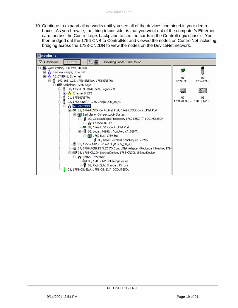
10. Continue to expand all networks until you see all of the devices contained in your demo boxes. As you browse, the thing to consider is that you went out of the computer’s Ethernet card, across the ControlLogix backplane to see the cards in the ControlLogix chassis. You then bridged out the 1756-CNB to ControlNet and viewed the nodes on ControlNet including bridging across the 1788-CN2DN to view the nodes on the DeviceNet network.
NOT-SP002B-EN-E
9/14/2004 2:51 PM Page 19 of 91
www.infoPLC.net

Summary
In this lab we added a driver in RSLinx that allowed us to bridge from Ethernet in our computer to a ControlLogix chassis. Then based on the types of cards within that chassis we could bridge to other networks. This is the power of NetLinx being able to seamlessly bridge across different networks: EtherNet/IP, ControlNet and DeviceNet.
Rockwell Automation offers customers a choice of networks, which provides complete flexibility to meet the needs of their unique application. Conceptually, the NetLinx architecture consists of three physically independent networks: EtherNet/IP, ControlNet and DeviceNet. The NetLinx architecture is an open platform that seamlessly overlaps device, control and information networks while providing complete connectivity at all levels. These networks can be mixed to suit the needs of a customer’s application efficiently without sacrificing performance. Rockwell’s central software package used to communicate on all of these networks is RSLinx.
. Congratulation you have completed Lab 1.
NOT-SP002B-EN-E
9/14/2004 2:51 PM Page 20 of 91
www.infoPLC.net

Lab 2: Using RSNetWorx and RSLogix 5000 Online (60 Minutes)
About This Lab
In this lab, we will introduce you to programming using RSLogix 5000 programming software.
First, you will launch RSLogix 5000 and create a new project for the Logix5563 controller.
Then, you will configure the Logix5563’s I/O tree to control the I/O in the 1794 FLEX chassis.
Next, you will configure the 1769-L35CR to consume the data from the 1794 Flex chassis.
Finally, you will use RSNetWorx to schedule your network.
You will learn how easy it is to configure, control and collect data from a Flex I/O module on ControlNet
You will learn how the online capabilities of RSNetWorx allow you to configure a ControlNet network
You will learn how ControlNet allows you to share data efficiently among controllers
Use the steps on the following pages to complete Lab 2.
NOT-SP002B-EN-E
9/14/2004 2:51 PM Page 21 of 91
www.infoPLC.net

Configuring I/O using RSLogix 5000 Software
In this section of the lab, you will launch RSLogix 5000 software and use it to populate the controllers I/O tree, configure I/O modules, add ladder code, download and verify your work.
1. Double Click on the RSLogix 5000 shortcut on the desktop to launch RSLogix 5000 software.
2. If the window it is not already maximized, maximize it by clicking the Maximize button in the top right of the window.
3. To create a new RSLogix 5000 project, from the main menu select File then select New…
NOT-SP002B-EN-E
9/14/2004 2:51 PM Page 22 of 91
www.infoPLC.net

4. Make the following changes and select OK.
5. Now it is time to configure the controller to talk to specific I/O devices. This is done by “adding modules” in the “I/O Configuration” portion of the project tree. In order to establish communication between devices you must enter specific data like node number, slot number, amount of data to be scanned and the rate at which you would like it to be scanned (RPI Requested Packet Interval)
NOT-SP002B-EN-E
9/14/2004 2:51 PM Page 23 of 91
www.infoPLC.net

6. First we will define the modules in the local chassis which include a 1756-ENBT and a 1756-CNB. (the 1756-OB16I will be defined later in the lab) Let’s start with the 1756-ENBT. In the left pane at the bottom, right click on I/O Configuration and select New Module…
`
1756-L63 1756-ENBT 1756-CNB 1756-OB16I
NOT-SP002B-EN-E
9/14/2004 2:51 PM Page 24 of 91
www.infoPLC.net

7. You will get the following screen. Scroll down until you find the 1756-ENBT/A. Select OK.
Select OK when the following screen appears.
TIP
There are various check boxes at the bottom of the Select Module Type screen that allow for filtering of potential modules. This can make it easier to find the desired module. The 1756-ENBT is a Communication module.
NOT-SP002B-EN-E
9/14/2004 2:51 PM Page 25 of 91
www.infoPLC.net

8. Make the following changes to the screen as shown below.
The Name can be any unique IEC 1131-3 compliant alpha-numeric name that the user wants. IEC1131-3 basically says that it must begin with an alpha character, can only be a maximum of 40 characters long and cannot contain certain characters like % or # .
The IP Address has previously been configured in the 1756-ENBT and can be verified by watching the IP address scroll across the front of the ENBT.
TIP
Electronic Keying prevents the inadvertent insertion of the wrong module in the wrong slot. RSLogix 5000 compares the following information for the inserted module to that of the configured slot:
Type, Vendor, Catalog Number, Major Revision and Minor Revision
Exact Match - all of the parameters described above must match or the inserted module will reject the connection.
Compatible Module - the Module Type, Catalog Number, and Major Revision must match. The Minor Revision of the module must be greater than or equal to the one specified in the software.
Disable Keying – the controller will not employ keying at all.
NOT-SP002B-EN-E
9/14/2004 2:51 PM Page 26 of 91
www.infoPLC.net

TIP
In this lab we will be using Disable Keying for all modules. By disabling keying it will give the greatest chances for success.
9. Now add the 1756-CNB in a similar manner as before using the data shown below. In the left pane at the bottom, right click on I/O Configuration and select New Module… 1756-CNB/D.
10. You have now configured the local chassis of your Logix5563 processor and the I/O tree should look as shown below.
NOT-SP002B-EN-E
9/14/2004 2:51 PM Page 27 of 91
www.infoPLC.net

11. Next we will add the 1794-ACNR15 FLEX I/O adapter, the 1794-IB10XOB6 discrete input/output combo card and the 1794-IE4XOE2 analog input/output combo card. These modules are on ControlNet and will be added under the 1756-CNB. The controller will bridge through the CNB to the 1794-ACNR15 to control the modules in the adapter’s chassis. Right click on the 1756-CNB and select New Module…
1794-ACNR15 1794-IE4XOE2 1794-IB10XOB6
NOT-SP002B-EN-E
9/14/2004 2:51 PM Page 28 of 91
www.infoPLC.net

12. Scroll until you find the 1794-ACNR15/C, select it and then select OK.
Select OK when the following screen appears.
NOT-SP002B-EN-E
9/14/2004 2:51 PM Page 29 of 91
www.infoPLC.net

13. Fill in the data as shown below and select Next.
TIP
Chassis Size: Select the appropriate number of modules connected to the communication adapter, between 1 and 8. In our chassis we have 2 modules so the chassis size is 2.
NOTE: We will cover the topic of Comm Format shortly. For now just leave it set for Rack Optimization.
NOT-SP002B-EN-E
9/14/2004 2:51 PM Page 30 of 91
www.infoPLC.net

14. Change the RPI (Requested Packet Interval) to 10 ms and select Finish
TIP
NUT: The Network Update Time is the smallest user configurable repetitive time cycle in milliseconds at which data can be sent on a ControlNet network. The range is 2 to 100 milliseconds and is configured in RSNetWorx.
RPI The Requested Packet Interval (RPI) is the rate that the user requests the data be moved to or from the module. The minimum and maximum RPI values are shown parenthetically to the right of the box/spin control. The RPI is entered by the user. Data can only be transferred at binary multiples (1,2,4,8,16,32,64 and 128) times the NUT.
API (not shown) The Actual Packet Interval (API) is the rate in milliseconds at which data is actually sent to or received from the device. This is configured by RSNetWorx software when edits are accepted and the network is scheduled. It is based on the NUT and the RPI. RSNetWorx will always make the API the closest number equal to or less than the RPI that is a binary multiple of the NUT. For example we have selected an RPI of 10 ms, if the NUT is 2 ms RSNetWorx will configure the API to be 8 ms. This is because 8 ms is the smallest binary multiple of the NUT that is less than or equal to 10 ms.
NOT-SP002B-EN-E
9/14/2004 2:51 PM Page 31 of 91
www.infoPLC.net

15. We will now add the I/O modules in the FLEX chassis. Right click on the 1794-ACNR15/C and select New Module….
Search for the Digital module 1794-IB10XOB6 and select OK.
NOT-SP002B-EN-E
9/14/2004 2:51 PM Page 32 of 91
www.infoPLC.net

Fill in the dialog box as shown and select Finish.
We will now add the analog module in the FLEX chassis. Right click on the 1794-ACNR15/C and select New Module… Search for the IE4XOE2 and select OK.
NOT-SP002B-EN-E
9/14/2004 2:51 PM Page 33 of 91
www.infoPLC.net
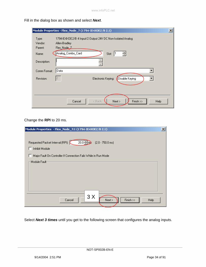
Fill in the dialog box as shown and select Next.
Change the RPI to 20 ms.
Select Next 3 times until you get to the following screen that configures the analog inputs.
3 X
NOT-SP002B-EN-E
9/14/2004 2:51 PM Page 34 of 91
www.infoPLC.net

Change Input Channel 0 to the selection shown and select Next.
On the Channel output dialog, change Output Channel 0 to match as shown below. Then select Finish.
NOT-SP002B-EN-E
9/14/2004 2:51 PM Page 35 of 91
www.infoPLC.net

16. We have now configured our Logix5563 controller to scan the I/O, both discrete and analog, in the FLEX chassis. The I/O tree should look as shown below. We have configured the discrete card to provide data over ControlNet at an RPI of 10 ms and we have configured the analog card to provide data over ControlNet at an RPI of 20 ms. Before this transfer of data begins we must still download the program to the Logix5563 and schedule the network with RSNetWorx.
17. Let us save our work. Click on the save icon at the top left of the RSLogix 5000 window.
18. To download we must first establish a path to the controller via RSLinx. In RSLogix 5000 click on Communications and select Who Active. This will bring up the RSLinx Who dialog and allow us to browse for the processor we want to download to.
NOT-SP002B-EN-E
9/14/2004 2:51 PM Page 36 of 91
www.infoPLC.net

Expand down to the 1756-L63/A Logix5563 processor and select it. Click on the Set Project Path button. Then click on the Download button.
When you get the following dialog select Download.
NOT-SP002B-EN-E
9/14/2004 2:51 PM Page 37 of 91
www.infoPLC.net
Tip
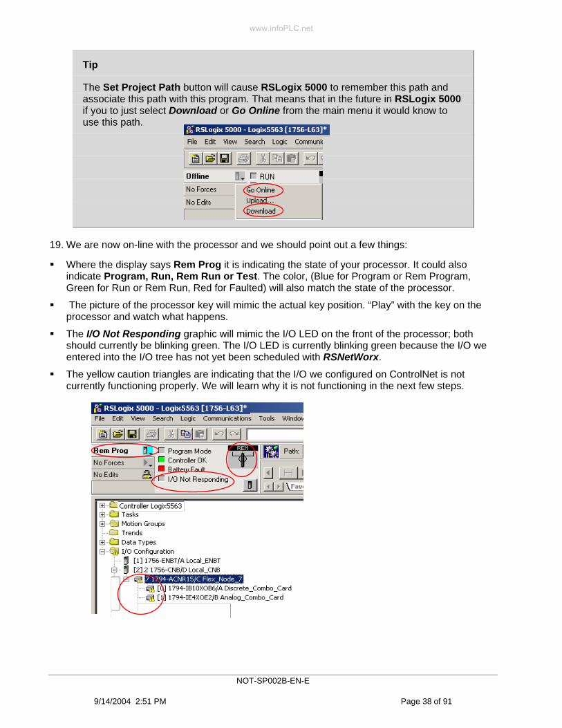
The Set Project Path button will cause RSLogix 5000 to remember this path and associate this path with this program. That means that in the future in RSLogix 5000 if you to just select Download or Go Online from the main menu it would know to use this path.
19. We are now on-line with the processor and we should point out a few things:
Where the display says Rem Prog it is indicating the state of your processor. It could also indicate Program, Run, Rem Run or Test. The color, (Blue for Program or Rem Program, Green for Run or Rem Run, Red for Faulted) will also match the state of the processor.
The picture of the processor key will mimic the actual key position. “Play” with the key on the processor and watch what happens.
The I/O Not Responding graphic will mimic the I/O LED on the front of the processor; both should currently be blinking green. The I/O LED is currently blinking green because the I/O we entered into the I/O tree has not yet been scheduled with RSNetWorx.
The yellow caution triangles are indicating that the I/O we configured on ControlNet is not currently functioning properly. We will learn why it is not functioning in the next few steps.
NOT-SP002B-EN-E
9/14/2004 2:51 PM Page 38 of 91
www.infoPLC.net

Let’s investigate the caution triangles. Select the 1794-ACNR15/C (Flex_Node_7) right click and select Properties
The following dialog will appear. Select the Connection tab.
Under Module Fault you see the error code for this connection. There are, of course many possible errors. Shown here is “Connection not scheduled”. That is because RSNetWorx still needs to be run to schedule the network.
RSNetWorx will be run later in the lab. For now let’s just continue on with the lab. This was done to illustrate some basic troubleshooting techniques.
NOT-SP002B-EN-E
9/14/2004 2:51 PM Page 39 of 91
www.infoPLC.net

If we select Properties for the Discrete_Combo_Card or the Analog_Combo_Card and look at the Connection tab we will see something similar to what is shown below.
Notice that no error code is being reported but that the Status says Waiting. This is because these modules are “Underneath” the FLEX adapter in the I/O tree so if the FLEX adapter is not functioning then there is no reason to try the individual module until the adapter is working.
Tip
As you progress through an I/O tree a device that is expanded under another device is called a Child and the device above it would be called the Parent. In this specific case the FLEX adapter is the Parent and either combo card would be considered the Child.
20. To be safe let’s save our current RSLogix 5000 file by clicking on the save icon . If you get a dialog similar to what is shown below, select YES to upload the tags.
NOT-SP002B-EN-E
9/14/2004 2:51 PM Page 40 of 91
www.infoPLC.net

Tip
Before we continue let’s have a discussion on Comm Formats. There are several ways of gathering data on ControlNet. Depending on the type of module selected and other factors like choosing scheduled Peer to Peer, you can have different Comm Format options available. When we entered the discrete combo card you were given the choices shown below. There are other possibilities and their definitions are also discussed below
Tip
Rack Optimization A method of establishing a connection to an adapter type device that allows all discrete inputs to send data via this connection and allows all discrete outputs to be controlled via this connection. After a Rack Optimized connection is configured to an adapter each module that you desire to communicate through this connection must also be selected as a Rack Optimized connection under the adapter. The Rack Optimized connection is an efficient way to gather all selected inputs and control all selected outputs in a single connection. A Rack Optimized connection will only transfer discrete input and output data. If a discrete card has additional data like status or diagnostics an individual connection must be used to gather the additional data.
None A method of establishing a connection to an adapter type device that allows connections to be made to individual modules using individual connections. After a None connection is configured to an adapter each module that you desire to communicate through this connection must also be configured under the adapter using any type of individual module connection. None is also good for peer to peer scheduled communication.
NOT-SP002B-EN-E
9/14/2004 2:51 PM Page 41 of 91
www.infoPLC.net

Input Data This connection types allows multiple Controllers to receive incoming data from the same device. If the connection is to an I/O device that requires configuration data, the Input Data connection will send the configuration data, one time, when the connection is first established. Be sure that if multiple connections (Input Data, Output Data or Rack Optimized) to the same device exist, that the configuration data in all Controllers must be identical. The incoming data does not need to already exist on the network, you can get Input Data with or without an existing Owner connection (Rack Optimized, Input Data or Output Data).
Listen Only-Input Data This connection type allows multiple Controllers to receive incoming data from the same device. No configuration data is sent with this type of connection. An Owner connection (Rack Optimized, Input Data or Output Data) must already exist to the device to produce Listen Only-Input Data. The transfer of this data is valid only if the Owner connection is active. If the Owner connection goes away the Listen Only-Input Data will no longer be produced. No additional ControlNet traffic is generated with this connection.
Output Data The one and only controller of outputs to that device. An Output Data connection to a device is the only connection that determines the mode (Prog or Run) of that particular device. If the connection is to an I/O device that requires configuration data, the Output Data connection will send the configuration data, one time, when the connection is first established.
21. Before we schedule the network let’s create a program for our other controller, the L35CR in the stand alone chassis. The program we already created has the Logix5563 processor controlling the I/O within the FLEX chassis. This is being done over ControlNet but it is still very traditional. One of the advantages of ControlNet is that multiple nodes can have access to the same data. We are going to illustrate this by creating a program in the L35CR processor that will have access to all of the inputs in the FLEX adapter. This is all based on the ControlNet producer/consumer model, which means that the FLEX adapter will produce the input data and two processors will consume the same data without any additional traffic. One data packet being read by two processors.
Open a new RSLogix 5000 window by selecting the proper shortcut on the desktop.
You can leave the previous RSLogix5000 window for the Logix5563 open.
NOT-SP002B-EN-E
9/14/2004 2:51 PM Page 42 of 91
www.infoPLC.net

If necessary maximize the window. Select File…New. Fill in the dialog as shown below and select OK.
1769-L35CR
NOT-SP002B-EN-E
9/14/2004 2:51 PM Page 43 of 91
www.infoPLC.net
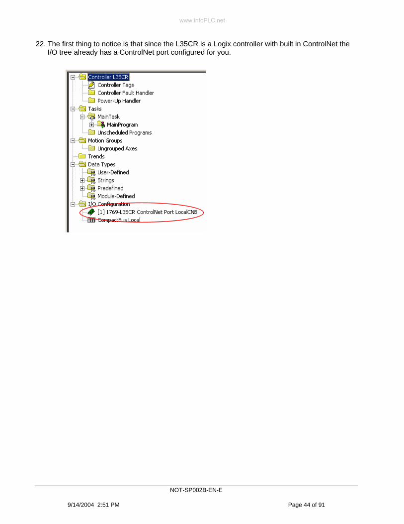
22. The first thing to notice is that since the L35CR is a Logix controller with built in ControlNet the I/O tree already has a ControlNet port configured for you.
NOT-SP002B-EN-E
9/14/2004 2:51 PM Page 44 of 91
www.infoPLC.net

To add the FLEX adapter: in the left pane at the bottom, right click on the 1769-L35CR ControlNet Port and select New Module… 1794-ACNR15/C and then OK.
Select OK when the following screen appears.
23. Fill in the data as shown below and select Finish.
NOT-SP002B-EN-E
9/14/2004 2:51 PM Page 45 of 91
www.infoPLC.net

For the discrete combo card: In the left pane at the bottom, right click on the 1794-ACNR15/C and select New Module… 1794-IB10XOB6 and then OK. Fill in the data as shown.
For the analog combo card:. In the left pane at the bottom, right click on the 1794-ACNR15/C and select New Module… 1794-IE4XOE2 and then OK. Fill in the data as shown.
NOT-SP002B-EN-E
9/14/2004 2:51 PM Page 46 of 91
www.infoPLC.net

24. You should now have an I/O tree in the L35CR that looks like the following.
25. Save the RSLogix 5000 L35CR project.
26. Download the program in a similar manner as before using the Communication…Who Active menu and the path shown below. Click the Set Project Path button. Notice that the path is out of the computer over Ethernet into the 1756-ENBT across the chassis backplane over to the 1756-CNB out ControlNet into the L35CR ControlNet port, across the1769 chassis backplane and over to the L35CR CompactLogix Processor. That was a very long path that was easily traversed. That is the power of NetLinx.
NOT-SP002B-EN-E
9/14/2004 2:51 PM Page 47 of 91
www.infoPLC.net

27. Select Download when the following screen appears.
28. Let us be safe and save the RSLogix 5000 project. Say Yes to Upload Tags.
29. So far we have created an RSLogix 5000 program in a Logix5563 controller that reads inputs and controls outputs of both a discrete and an analog card within a FLEX chassis. We have created different RSLogix 5000 program in an L35CR controller that will receive all of the same inputs both discrete and analog from the same FLEX chassis. Now we need to configure and activate our network using RSNetWorx.
NOT-SP002B-EN-E
9/14/2004 2:51 PM Page 48 of 91
www.infoPLC.net
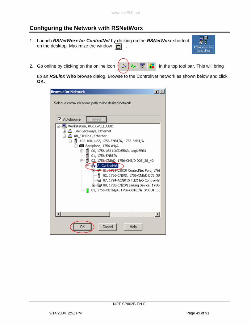
Configuring the Network with RSNetWorx
1. Launch RSNetWorx for ControlNet by clicking on the RSNetWorx shortcut on the desktop. Maximize the window .
2. Go online by clicking on the online icon in the top tool bar. This will bring
up an RSLinx Who browse dialog. Browse to the ControlNet network as shown below and click OK.
NOT-SP002B-EN-E
9/14/2004 2:51 PM Page 49 of 91
www.infoPLC.net

3. RSNetWorx will immediately go out and browse ControlNet for all of the nodes on the network and draw a graphical representation of the network. You should have something similar to what is shown below.
NOT-SP002B-EN-E
9/14/2004 2:51 PM Page 50 of 91
www.infoPLC.net

Tip
Notice the green plus signs. That is an indication that the node is seen on the network but not currently in the RSNetWorx offline file. There are other possible symbols and the legend is shown below. You can get this same information in RSNetWorx by clicking on the Symbol Legend in the top RSNetWorx tool bar.
NOT-SP002B-EN-E
9/14/2004 2:51 PM Page 51 of 91
www.infoPLC.net

4. Enable edits in RSNetWorx by clicking on the Edits Enabled box at the top left of the window.
RSNetWorx will automatically go out and read the network configuration and remove the green plus signs as the online and offline files now match.
5. We now need to configure the overall network parameters like the NUT, SMAX and UMAX. This is done from the main menu Network Properties….
Tip
NUT: The Network Update Time is the smallest user configurable repetitive time cycle in milliseconds at which data can be sent on a ControlNet network. The range is 2 to 100 milliseconds and is configured in RSNetWorx.
SMAX Scheduled Maximum Node The highest node number that can transmit data within the scheduled bandwidth.
UMAX Unscheduled Maximum Node is the highest node number that can use unscheduled time on a ControlNet link. Nodes set at addresses higher than the UMAX will not be able to communicate on the network.
NOT-SP002B-EN-E
9/14/2004 2:51 PM Page 52 of 91
www.infoPLC.net

Change your parameters to match what is shown below and click OK.
Tip
The Media Configuration tab shown above is where you would go to configure any repeaters, fiber or long coax runs into your system. We do not need to enter anything here because our network is so small.
6. Next we will save our work, which will actually complete the scheduling of our network. Click on the Save icon.
NOT-SP002B-EN-E
9/14/2004 2:51 PM Page 53 of 91
www.infoPLC.net

Save the configuration under the File name CLX and click Save.
7. When the following dialog appears click OK.
If you get a Retry dialog select Retry.
NOT-SP002B-EN-E
9/14/2004 2:51 PM Page 54 of 91
www.infoPLC.net

Tip
Optimize and re-write schedule for all connections. Click this radio button to create a new schedule based on the entire configuration. This selection reschedules the entire network and temporarily shuts down all connections in order to make the schedule change. This method of saving results in the most efficient scheduling algorithm but has the greatest impact on a running system.
Merge changes into existing schedule Click this radio button to include only the changes you have made during this session into the existing schedule. This option is not available if one of the following occurs: A network parameter changes. The pending schedule exceeds the network bandwidth. A processor on the network does not support the merge option. This selection reschedules only the changed nodes by merging them into the existing schedule, temporarily shutting down only the changed nodes to make the schedule change. This method of saving has the least impact on a running system, but results in the least efficient scheduling algorithm. If the network you are working on has never before been scheduled “Merge” will be unavailable.
If the following dialog appears click on Yes. This is a warning stating that if you select Yes on a running network all scheduled communication will be temporarily interrupted while the network is rescheduled.
RSNetWorx is now off building the network and downloading the schedule. That means that RSNetWorx is reading all of the connections on the network, deciding if what you have programmed is valid and deciding which NUT each scheduled connection will occur in. If all criteria is passed RSNetWorx will download the schedule to the appropriate nodes.
NOT-SP002B-EN-E
9/14/2004 2:51 PM Page 55 of 91
www.infoPLC.net

8. At this point everything should be working. This can be verified by checking the I/O LED on the front of both processors (they should be solid green). Check the I/O OK indicator in both RSLogix 5000 programs (they should be solid green) and there should no longer be any yellow caution triangles in the I/O tree of either processor. Be sure that both processors are in Rem Prog mode.
Let us further investigate our working system by adding some ladder programming within our processor that will use the pushbuttons, pilot lights, pot and meter on our demo box to verify our I/O operation. We will add a rung that moves the state of the input pushbuttons to the output pilot lights. We also will add a rung that moves the analog input value of the pot to the analog output of the meter.
9. Bring up the instance of RSLogix5000 for the Logix5563 controller (the one in the big demo box). Browse to the Main Routine and double click on it.
That will bring up a rung in edit mode as shown below.
NOT-SP002B-EN-E
9/14/2004 2:51 PM Page 56 of 91
www.infoPLC.net

10. Double click on the blue area and you will get the following window. Type MOV in the box and hit the enter key. This will insert a MOV instruction into the ladder.
11. Double click on the single ? next to Source and you will get a drop down menu. Be sure Controller Scoped Tags is selected. Click on the drop down menu. Browse until you find the tag called Flex_Node_7:0:I.Data. Note: you may need to move the header slider bar over (circled vertically) to see the entire tag name. Hit enter.
NOT-SP002B-EN-E
9/14/2004 2:51 PM Page 57 of 91
www.infoPLC.net
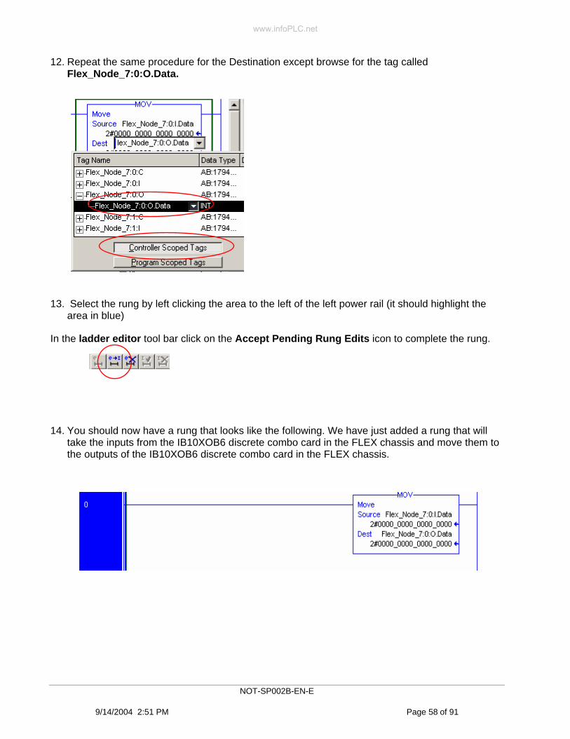
12. Repeat the same procedure for the Destination except browse for the tag called Flex_Node_7:0:O.Data.
13. Select the rung by left clicking the area to the left of the left power rail (it should highlight the area in blue)
In the ladder editor tool bar click on the Accept Pending Rung Edits icon to complete the rung.
14. You should now have a rung that looks like the following. We have just added a rung that will take the inputs from the IB10XOB6 discrete combo card in the FLEX chassis and move them to the outputs of the IB10XOB6 discrete combo card in the FLEX chassis.
NOT-SP002B-EN-E
9/14/2004 2:51 PM Page 58 of 91
www.infoPLC.net

15. Double click on the (End) rung to add second rung in a similar manner. When finished the rung should look like the following.
We have just added a rung that will take the CH0 analog input from the IE4XOE2 analog combo card in the FLEX chassis and move it to the CH0 output of the IE4XOE2 analog combo card in the FLEX chassis.
Use the Keyswitch to place the Processor in RUN mode.
Verify that these rungs work properly by pushing the pushbuttons (DI0-DI3) on the demo box and you should see the pilot lights (DO0-DO3) on the demo box come on.
Move the pot AI0 on the demo box and you should see the meter AO0 move.
We have successfully:
• Configured the I/O of the Logix5563 processor using RSLogix 5000.
• Scheduled the ControlNet network using RSNetWorx.
• We added rungs using RSLogix 5000 to verify our work.
So far every thing we have done is pretty basic and any PLC on the market can accomplish the same tasks. Next we will see the power of ControlNet by configuring the I/O in the other processor and viewing some ControlNet specific features such as the ability to have multiple processors gather input data from the same source.
16. Save your program and choose Upload tags when prompted.
17. Switch to the instance of RSLogix 5000 for the L35CR controller in the standalone chassis. This processor is receiving the same input data from the FLEX chassis as the other controller but we need to verify this.
NOT-SP002B-EN-E
9/14/2004 2:51 PM Page 59 of 91
www.infoPLC.net

18. Double click on the Controller Tags icon in the controller tree.
You should get a screen similar to what is shown below. Be sure the display is configured as shown.
19. Expand and drill down until your display is similar to what is shown below. Push the pushbuttons DI0-DI3 and you should see the data in the tag Flex_Node_7_Listen:0:I.Data change. Move the pot AI0 and you should see the data in the tag Flex_Node_7_Listen:1:I.Ch0InputData change.
NOT-SP002B-EN-E
9/14/2004 2:51 PM Page 60 of 91
www.infoPLC.net

20. Save your program and upload tags when prompted.
In our L35CR controller we have just verified that it is receiving the same input data from the FLEX adapter that our Logix5563 controller is. This is done over ControlNet with a single packet being sent from the FLEX adapter with both processors receiving it.
Congratulation you have completed Lab 2.
Exit RSNetWorx
Summary In this Lab we have:
Created programs for 2 different Logix controllers
Defined and configured I/O on ControlNet within these controllers
Downloaded ladder programs via RSLinx
Scheduled the ControlNet network using RSNetWorx
Produced and controlled I/O data within a processor over ControlNet
Consumed input data within another controller
Learned some basic programming techniques within RSLogix 5000
NOT-SP002B-EN-E
9/14/2004 2:51 PM Page 61 of 91
www.infoPLC.net

www.infoPLC.net

Lab 3: Using RSNetWorx and RSLogix 5000 Offline (20 Minutes)
About This Lab
In this lab we will introduce you to the offline operations between RSLogix 5000 and RSNetWorx software. This is a feature that was added into V12 of RSLogix 5000 and V4 of RSNetWorx.
First you will open 3 separate RSLogix 5000 files that have been previously developed.
Then you will use those RSLogix 5000 programs offline and link them to RSNetWorx and observe the network characteristics offline.
You will learn how RSNetWorx can be used to configure ControlNet and manage offline performance without the need to have all of the hardware available.
You will learn how to avoid performance issues early in the design cycle.
You will learn of the unique advantages of a scheduled network like ControlNet that will allow you to determine performance and guarantee I/O update times regardless of network loading.
You will learn how easily ControlNet supports multiple controllers on the same network exchanging I/O and peer data.
Finally you will learn how to detect potential ControlNet bandwidth errors and how to correct them.
Use the steps on the following pages to complete Lab 3.
NOT-SP002B-EN-E
9/14/2004 2:51 PM Page 63 of 91
www.infoPLC.net

Using RSNetWorx Offline
Before we begin: In this lab we will start with 3 previously created RSLogix 5000 programs. These programs represent 3 different ControlNet nodes on the same network (nodes1, 2, and 3). Each consists of a Logix5563 processor and a 1756-CNBR in a chassis. Each of these nodes produces a tag of 120 DINTs and each will consumes a tag of 120 DINTs from the other two Logix5563s. That means that each node sends a single packet 120 DINTs and each node will receive two different packets each of a size equal to 120 DINTs. All of the I/O and tags needed to accomplish this have already been configured.
1. Start a new instance of RSLogix 5000.
2. Open the RSLogix 5000 file called one. (it is in the C:\RSLogix 5000\Projects directory which should be the default)
3. Open 2 more instances of RSLogix 5000 and open the RSLogix 5000 files titled two and three.
You should now have 3 instances of RSLogix 5000 open, each loaded with one of the following files: one two or three.
NOT-SP002B-EN-E
9/14/2004 2:51 PM Page 64 of 91
www.infoPLC.net

4. The first thing we must do is “associate” the RSLogix 5000 files with an RSNetWorx file.
Tip
RSLogix 5000 files are also called ACD files because when saved it is stored as filename.ACD. RSNetWorx files are also called xc files because when saved they are stored as filename.xc. From now on we refer to them as ACD or xc files.
Tip
By associate we mean configure the ACD file(s) to a specific xc file. Multiple ACD files can be configured to a single xc file because each ACD is basically representing a single node on the ControlNet network.
5. Select the RSLogix 5000 instance with the ACD file called one. In the I/O tree right click on the local_CNB and select Properties.
NOT-SP002B-EN-E
9/14/2004 2:51 PM Page 65 of 91
www.infoPLC.net

6. Go to the RSNetWorx tab. Type ‘three_nodes’ as the name of the xc file and click on Apply.
Click YES when asked to create three_nodes.xc
7. Repeat this process 2 more times for programs two and three. This time you should not get the warning about creating the xc file because it has been created.
Save ACD files one, two and three
8. Launch RSNetWorx for ControlNet.
NOT-SP002B-EN-E
9/14/2004 2:51 PM Page 66 of 91
www.infoPLC.net

9. From the File menu select Open…
10. Use the up folder button to browse to C:\RSLogix 5000\Projects and Open the xc file called three_nodes.
NOT-SP002B-EN-E
9/14/2004 2:51 PM Page 67 of 91
www.infoPLC.net

11. You should get an empty network with the following information displayed at the bottom.
These , informational dialogs are RSNetWorx’s way of indicating what is going on in this xc file. Mainly these dialogs are saying that RSNetWorx needs to incorporate data from nodes 1, 2 and 3 from the RSLogix 5000 ACD files. To include these edits you must enable edits.
12. Check the Edits Enabled box.
NOT-SP002B-EN-E
9/14/2004 2:51 PM Page 68 of 91
www.infoPLC.net

RSNetWorx should now build a graphical picture of our network incorporating all of the data from ACD files one, two and three. You should now have a network that looks like the following.
one.ACD two.ACD
three.ACD
Note: These “bubbles” are not actually
on the screen. They are here for
illustrative purposes.
NOT-SP002B-EN-E
9/14/2004 2:51 PM Page 69 of 91
www.infoPLC.net

From the main menu select Network … Properties… fill in the dialog as shown below.
Click OK.
NOT-SP002B-EN-E
9/14/2004 2:51 PM Page 70 of 91
www.infoPLC.net

Estimating Performance Off-Line
So far we have associated 3 ACD files from a single network with an xc file. RSNetWorx then built the network offline. We then configured the NUT, SMAX and UMAX. Now we can gather information about our network from RSNetWorx. This can now be done off line with any version of RSLogix 5000 V12 or greater.
1. First we will look at the overall network traffic. At the top of the RSNetWorx window you should see data similar to what is shown below. This is giving us data on the scheduled and unscheduled bandwidth of the entire network (later we will be looking and bandwidth of individual nodes).
Unscheduled Bytes Per Sec: Tells us how many bytes per second are available to be used for unscheduled traffic after the scheduled bytes of data are subtracted. This number only indicates what is available for use it is not an indication of how many bytes are or are not actually being used. The current indication reads about 540 Kbytes per second available. An empty network would have about 560 Kbytes available. This tells us that this network still has plenty of unscheduled bandwidth available.
Pending Optimized or Merged Edits: Optimized and Merged edits were discussed earlier in Lab 2 and are mostly related to “who” must go to program mode to schedule the network. The most efficient use of network bandwidth is done when Optimized Edits is used but requires all nodes to be in program mode. Merged Edits is less efficient but only requires edited nodes to be in program mode. In our case both columns (Pending Optimized and Pending Merged Edits show equal bandwidth (5.81% Avg. and 20.14% Peak) because we have changed SMAX and UMAX values which will require all nodes to be in program mode. Should the two columns show different values it would be an indication in network efficiency if Merged Edits is selected at the time of the save.
Average and Peak Scheduled Band Network:. When RSNetWorx schedules the network it looks at all of the scheduled data that must be transmitted from each node and how often it must be transmitted. It will arrange the data to be sent in certain NUTs. Since not all data is necessarily sent every NUT from each node, some NUTs will have more traffic in them than others. The peak number is the worst case NUT and the average is a bandwidth average of 128 NUTs. The closer to 100% that these numbers are the “busier” the network is. If the Peak is near 100% but the Average is very low that would indicate a network was not that busy because it probably means that a single NUT is transmitting very large packets and near 100%, but the other NUTs do not have that much to transmit so the network is not that busy.
NOT-SP002B-EN-E
9/14/2004 2:51 PM Page 71 of 91
www.infoPLC.net

Tip
Here are some general rules about Average and Peak Scheduled Network Bandwidth
1) As these numbers approach 100% it is an indication of how much scheduled bandwidth is used (the amount of unscheduled bandwidth available would be 100%-scheduled bandwidth). This is not an indication of the likelihood of this network to function properly. To function properly the Node Network Usage (to be discussed shortly) is a much more important factor.
2) If these numbers are close to 100% it will mean that there is little to no room for future expansion without making major changes and that there is not much bandwidth available for unscheduled traffic. If you can guarantee that there will be no future expansion and that you do not need much unscheduled bandwidth then it is acceptable to have these number approach 100%.
3) If this number goes over 100% you do not have a valid network and you will get errors and not be able to schedule the network without making changes.
2. Right click on node 1 in RSNetWorx and then select Properties.
NOT-SP002B-EN-E
9/14/2004 2:51 PM Page 72 of 91
www.infoPLC.net

You will get a dialog similar to the one shown below. Select the ControlNet tab.
This is the Node Network Usage information. This tab is an indication of what this specific node is doing on ControlNet. The meanings of Peak, Average, Optimized and Merged that we just discussed still apply here but they are for this specific node and not for the entire network.
Average/Peak Scheduled Usage is a representation of the amount of data being sent from this specific node with the average and peak definitions from before still applying. In simple terms a ControlNet node can only transmit about 250 16 bit words per NUT; 100% would mean that a node was transmitting about 250 words per NUT. In our case we have a Peak of 95.69% so in at least 1 NUT we must be sending a lot of data. Our Average of 10.05% would tend to indicate that in all of the other unique NUTS we probably are not sending much data. In our case if you were an advanced user you could look at the file, one.ACD and you would find that the only thing we are sending is once every 16 NUTs we produce a packet of 240 16 bit words this gives our large Peak and our small Average. (NUT of 5ms, RPI=100ms from consumed value tag_2 therefore API=80ms or once every 16 NUTs)
Average/Peak Received Usage is a representation of the amount of data being received by this specific node with the average and peak definitions from before still applying. In our case we have a Peak of 14.29% and an Average of 5.36%.
NOT-SP002B-EN-E
9/14/2004 2:51 PM Page 73 of 91
www.infoPLC.net
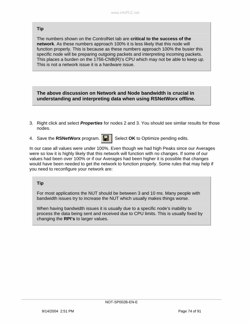
Tip
The numbers shown on the ControlNet tab are critical to the success of the network. As these numbers approach 100% it is less likely that this node will function properly. This is because as these numbers approach 100% the busier this specific node will be preparing outgoing packets and interpreting incoming packets. This places a burden on the 1756-CNB(R)’s CPU which may not be able to keep up. This is not a network issue it is a hardware issue.
The above discussion on Network and Node bandwidth is crucial in understanding and interpreting data when using RSNetWorx offline.
3. Right click and select Properties for nodes 2 and 3. You should see similar results for those nodes.
4. Save the RSNetWorx program. Select OK to Optimize pending edits.
In our case all values were under 100%. Even though we had high Peaks since our Averages were so low it is highly likely that this network will function with no changes. If some of our values had been over 100% or if our Averages had been higher it is possible that changes would have been needed to get the network to function properly. Some rules that may help if you need to reconfigure your network are:
Tip
For most applications the NUT should be between 3 and 10 ms. Many people with bandwidth issues try to increase the NUT which usually makes things worse.
When having bandwidth issues it is usually due to a specific node’s inability to process the data being sent and received due to CPU limits. This is usually fixed by changing the RPI’s to larger values.
NOT-SP002B-EN-E
9/14/2004 2:51 PM Page 74 of 91
www.infoPLC.net

Close all three instances of RSLogix 5000 and close RSNetWorx
Congratulation you have completed Lab 3.
Summary In this Lab we have:
Linked 3 different ACD files to one xc file.
Learned about Network bandwidth
Learned about Node bandwidth
Scheduled a ControlNet network offline using RSNetWorx Achieved a basic understanding of the likelihood of a network to function properly
ControlNet is a scheduled network, which differentiates it from EtherNet/IP, DeviceNet and most other networks. All time critical I/O data is scheduled on ControlNet. Unscheduled data such as HMI and program downloads will not affect performance of the scheduled data. This is one of the main benefits of ControlNet and why ControlNet is optimized as a backbone for distributed I/O and peer to peer interlocking.
NOT-SP002B-EN-E
9/14/2004 2:51 PM Page 75 of 91
www.infoPLC.net

www.infoPLC.net

Lab 4: Basic Troubleshooting Techniques and Tips for ControlNet (10 Minutes)
About This Lab
In this lab, we will introduce you to some basic troubleshooting techniques to diagnose network issues.
First you will learn to distinguish between the two major ControlNet errors: Physical Media and Programming.
You will learn how every ControlNet node contains built in network error counters that can be used to detect errors than can be used to diagnose issues and avoid downtime.
You will view the various ControlNet diagnostic counters.
You will learn how nodes on ControlNet contain built in statistics that can be monitored using RSLinx to help manage your network.
Finally you will learn about ControlNet signatures.
Use the steps on the following pages to complete Lab 4.
NOT-SP002B-EN-E
9/14/2004 2:51 PM Page 77 of 91
www.infoPLC.net

Physical and Programming errors
Most ControlNet issues can be broken down into either physical or programming. Physical errors are related to media and installation. Typical physical problems would include;
• Improper termination resistors
• Improper coax cable
• Poor BNC terminations on the coax
• “kinks” in the coax
• Improper use of or missing repeaters
• Running of coax close to high power lines
• Having the coax shield connected to ground.
Typical programming errors would include not using RSNetWorx, exceeding bandwidth parameters and issues with revision.
Physical Issues
Physical errors can be identified by two major methods. Method 1 would be to look at the CHA and/or CHB LEDs on any ControlNet module. Under normal circumstances these LEDs should be solid green. Method 2 would be to look at the diagnostic counters available via RSLinx for each node. These counters will mimic the CHA/B LEDs but you will be able to see errors over time. This method would be especially useful for either low error rates or intermittent errors.
1. Use the shortcut on the desktop to launch RSLinx.
NOT-SP002B-EN-E
9/14/2004 2:51 PM Page 78 of 91
www.infoPLC.net

2. Select the RSWho icon and browse from Ethernet over ControlNet to the 1794-ACNR at node7. Select it, right click and select Station Diagnostics as shown.
NOT-SP002B-EN-E
9/14/2004 2:51 PM Page 79 of 91
www.infoPLC.net

3. The following screen will appear. RSLinx can display a similar screen for all nodes on ControlNet.
First some basics: The counters within the box are all double integers and will continue to increment to a high value and rollover. All other counters will increment to 255 and rollover back to zero. In your network you should see the Channel B error count continuously incrementing to 255 and rolling over to zero. This is because we have a Channel A only configured network and there is no traffic on Channel B. This counter can be ignored if you are not using Channel B.
As a general rule it is not necessary to know the exact meaning of all of these counters. For the vast majority of installations what is important is that all of the counters that are circled above are usually related to noise in the system. That means that it is a physical problem and that some type of media issue exists. Knowing the exact meaning of the counter will not usually help narrow down the media issue. So walk away from this knowing that if these counters are incrementing you have noise on the system and it is related to media/installation and that these issues must be taken care of first.
NOT-SP002B-EN-E
9/14/2004 2:51 PM Page 80 of 91
www.infoPLC.net

4. If you right click in any of the available white space you will get a window that will allow you to either freeze or reset the counters. The Reset Counters command is useful in tracking errors over time.
5. There is a second screen available only on the CNB(R) that can provide additional troubleshooting data. You can view this screen by browsing to the CNBR at node 2, selecting it and right clicking and selecting Module Statistics.
NOT-SP002B-EN-E
9/14/2004 2:51 PM Page 81 of 91
www.infoPLC.net

6. That will bring up a screen similar to the following. Select the Connection Manager tab. This screen is especially useful in troubleshooting Node Network Usage issues (discussed earlier in Lab 4).
NOT-SP002B-EN-E
9/14/2004 2:51 PM Page 82 of 91
www.infoPLC.net

The screen below is from the Lab 4 section on Node Network Usage
Some of the most important pieces of data shown on the Connection Manager tab are the CPU Utilization and the Connections Used displays.
Tip
Connections Used: The CNB(R) has a total of 64 connections available for scheduled and unscheduled connections. As the Connections Used number approaches 64, it is possible to run out of connections. Approaching 64 connections could limit a user’s ability to:
1) Expand the system.
2) Make an unscheduled connection to go-online through the CNB(R).
3) Have HMI’s read the controllers tags through the CNB(R).
4) Trigger messages in ladder logic routed out of the CNB(R).
NOT-SP002B-EN-E
9/14/2004 2:51 PM Page 83 of 91
www.infoPLC.net

TIP
CPU Utilization is an indication of how busy the CNB(R) is servicing the network. If this number goes over 100% it is likely that you would experience a dropping of connections. The display of the CNB(R) will also scroll a latched error message indicating that the bandwidth was exceeded.
1) As the Peak and Average Node Network Usage increases so will the CPU Utilization.
2) In general it is recommended to keep this number in the 50-70% range.
3) After you schedule the network with RSNetWorx it is recommended you monitor this number and make adjustments accordingly.
NOT-SP002B-EN-E
9/14/2004 2:51 PM Page 84 of 91
www.infoPLC.net

Keepers and Signatures
1. Launch a new instance of RSNetWorx.
2. From the main menu select File and then New.
3. For the Configuration Type select ControlNet Configuration and then OK.
4. Click on the Online icon………….
NOT-SP002B-EN-E
9/14/2004 2:51 PM Page 85 of 91
www.infoPLC.net

5. Browse to our ControlNet network, select it, and click OK.
NOT-SP002B-EN-E
9/14/2004 2:51 PM Page 86 of 91
www.infoPLC.net
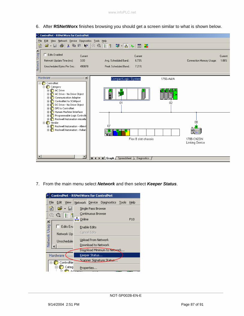
6. After RSNetWorx finishes browsing you should get a screen similar to what is shown below.
7. From the main menu select Network and then select Keeper Status.
NOT-SP002B-EN-E
9/14/2004 2:51 PM Page 87 of 91
www.infoPLC.net

8. You should get a screen similar to what is shown below. The actual hex value shown on your screen may be different than what is shown below, that does not mean that there is a problem.
Tip
A network Keeper is a ControlNet node with the capability to store and apply scheduling information and network parameters such as the NUT, SMAX and UMAX and Media Redundancy selections for a unique network configuration. Keeper devices are: 1784-KTCS, 1784-PCICS, all PLC5C’s, 1756-CNB(R), 1747-SCNR and 1788-CNCR.
Signatures are unique hidden values assigned by RSNetWorx to each keeper when the ControlNet Configuration edits are saved. There are two types of signatures, Keeper Signatures and Scanner Signatures. The intent of the Keeper Signature is to determine if the newly joining keeper should be valid or invalid. The intent of the Scanner Signature is to prevent an unauthorized scanner from opening scheduled connections. Every keeper stores the single network keeper signature and every keeper stores the scanner signatures for the all keepers on the entire network.
NOT-SP002B-EN-E
9/14/2004 2:51 PM Page 88 of 91
www.infoPLC.net

Tip
In a properly configured network there will be one and only one Active Keeper which will be the lowest node number that has keeper capability. All other Keeper Capable nodes should be valid. The actual value of the signature shown in hex is not important, other than all Keeper Capable nodes should have the same hex value displayed. Each time RSNetWorx is used to reschedule the network you should examine this screen and verify that all nodes are valid. If one or more nodes are not valid you should either re-run RSNetWorx or select the invalid node and then click the Update Keeper button.
Important
It is strongly recommended that after each time you re-schedule the network you monitor the Keeper Status screen and verify that all nodes are valid. When the Keeper Status screen indicates that all nodes are valid all programs from all controllers should be uploaded and saved.
9. Close the Keeper Status screen by clicking the Close button .
10. From the main menu select Network and then select Scanner Signature Status
NOT-SP002B-EN-E
9/14/2004 2:51 PM Page 89 of 91
www.infoPLC.net

11. You should get a screen similar to what is shown below. The actual hex value shown on your screen may be different than what is shown below, that does not mean that there is a problem.
Read the circled text.
The actual hex value of the signature is not important as long as the hex value In the Scanner matches the hex value In the Online Active Keeper.
Tip
The Scanner Signatures are a security check to be sure that nodes joining this network were actually configured for this network at the same time as the Active Keeper. A node will not be allowed to open scheduled connections on the network unless his Scanner Signature matches the Scanner Signature for its node number stored in the Active Keeper.
For example: If a working network had a CNB(R) physically fail and you grabbed a CNB(R) from another network as a replacement. The replacement CNB(R) would have a different schedule stored in its memory and therefore a different Scanner Signature. It would then not be able to open any of its scheduled connections because those connections were intended for a different network.
12. Close the Scanner Signature Status screen
NOT-SP002B-EN-E
9/14/2004 2:51 PM Page 90 of 91
www.infoPLC.net

Congratulations you have completed Lab 4.
Summary In this Lab we have:
Learned about typical ControlNet physical issues.
Learned how to use ControlNet’s nodes Diagnostic Counters.
Learned how to use the CNB(R)s Connection Manager information.
Learned about Keeper Signatures.
Learned about Scanner Signatures.
Congratulations you have completed your Introduction to ControlNet using ControlLogix lab.
NOT-SP002B-EN-E
9/14/2004 2:51 PM Page 91 of 91
www.infoPLC.net