ethernet, controlnet, and devicenet - uniroma3
TRANSCRIPT

66 IEEE Control Systems Magazine February 2001
By Feng-Li Lian, James R. Moyne, and Dawn M. Tilbury
Ethernet, ControlNet, and DeviceNet
he traditional communi-cation architecture for con-trol systems, which has beensuccessfully implemented inindustry for decades, is
point to point. Expandingphysical setups and functionality, how-ever, are pushing the limits of thepoint-to-point architecture. Hence, atraditional centralized point- to-pointcontrol system is no longer suitable tomeet new requirements such as modu-larity, decentralization of control, inte-grated diagnostics, quick and easymaintenance, and low cost [1]. Networksystems with common bus architec-tures, called networked control sys-tems (NCSs), provide several advantages such as smallvolume of wiring and distributed processing. Especially withrespect to manufacturing systems, NCS architectures thatutilize processing power at each node allow for themodularization of functionality and standard interfaces forinterchangeability and interoperability. Object-based devicemodels separate generic, device-type-specific from manufac-turer-specific functionality.
Many different network types have been promoted foruse in control systems. In this article, we compare three ofthem: the Ethernet bus, with carrier sense multiple access
with collision detection (CSMA/CD), token-passing bus (e.g.,ControlNet), and controller area network (CAN) bus (e.g.,DeviceNet). We consider how each control network couldbe used as a communication backbone for a networked con-trol system connecting sensors, actuators, and controllers.A detailed discussion of the medium access control (MAC)sublayer protocol for each network is provided. For eachprotocol, we study the key parameters of the correspondingnetwork when used in a control situation, including networkutilization, magnitude of the expected time delay, and char-acteristics of time delays. Simulation results are presented
©20
00Im
age
100
Ltd.
Lian and Tilbury ([email protected]) are with the Department of Mechanical Engineering, University of Michigan, 2250 G.G. BrownBuilding, 2350 Hayward St., Ann Arbor, MI 48109-2125, U.S.A. Moyne is with the Department of Electrical Engineering and Computer Sci-ence, University of Michigan, Ann Arbor, MI 48109-2125, U.S.A.
0272-1708/01/$10.00©2001IEEE

for several different scenarios, and the advantages and dis-advantages of each network are summarized.
Performance ObjectivesDistributed systems contain a large number of intercon-nected devices to perform the desired operations over alarge area of coverage; examples include industrial automa-tion, building automation, office and home automation, in-telligent vehicle systems, and advanced aircraft andspacecraft [2]-[6]. Data networks or control networks may beused, depending on the information exchanged. Data net-works are characterized by large data packets, relatively in-frequent bursty transmission, and high data rates; theygenerally do not have hard real-time constraints. Control net-works, in contrast, must shuttle countless small but fre-quent packets among a relatively large set of nodes to meetthe time-critical requirements. The key element that distin-guishes control networks from data networks is the capabil-ity to support real-time or time-critical applications [7].
With NCSs, decision and control functions (including sig-nal processing) can be distributed among controllers on thenetwork. When designing an NCS, however, a new constraintmust be accommodated—the limited bandwidth of thecommunication network. The effective bandwidth of a net-work is defined as the maximum amount of meaningful datathat can be transmitted per unit time, exclusive of headers,padding, stuffing, etc.; this contrasts with the more tradi-tional definition of network bandwidth, which is the numberof raw bits transmitted per unit time. Four factors affect theavailability and utilization of the network bandwidth: thesampling rates at which the various devices send informa-tion over the network, the number of elements that requiresynchronous operation, the data or message size of the in-formation, and the MAC sublayer protocol that controls theinformation transmission [8]. Therefore, to achieve the tim-ing constraints and guarantee the performance of NCSs, net-work traffic optimization algorithms and controller designfor the devices connected to the network must be analyzed.
The performance metrics of network systems that im-pact control system requirements include access delay,transmission time, response time, message delay, messagecollisions (percentage of collisions), message throughput(percentage of packets discarded), packet size, network uti-lization, and determinism boundaries. For control systems,candidate control networks generally must meet two maincriteria: bounded time delay and guaranteed transmission;that is, a message should be transmitted successfully withina bounded time delay. Unsuccessfully transmitted or largetime-delay messages from a sensor to an actuator, for exam-ple, may deteriorate system performance or make systemsunstable. Several protocols have been proposed to meetthese requirements for control systems. They include Ether-net (IEEE 802.3:CSMA/CD), token bus (IEEE 802.4), tokenring (IEEE 802.5), and CAN (CSMA/AMP). Control networksare typically based on one of two medium access protocols:
February 2001 IEEE Control Systems Magazine 67
Nomenclature.All variables defined in this article are time varying.
Ndata Data size (bytes).
Novhd Overhead size (bytes).
Npad Padding frame (bytes).
Nstuff Stuffing frame (bytes).
Peff Network efficiency (%).
Putil Network utilization (%).
Tblock Blocking time at the source node.
Tbit Bit time.
Tdcode Decoding time at the destination node.
Tdcomp Computing time at the destination node.
Tdelay Time delay of a message.
Tframe Frame time on the network medium.
Tguard Guardband period.
Tmax Maximum simulation time.
Tnode Maximum token holding time.
Tperi Message period.
Tretx Retransmission time on the network medium.
Tpost Postprocessing time at the destination node.
Tpre Preprocessing time at the source node.
Tprop Propagation time on the network medium.
Tqueue Queuing time at the source node.
Tresid Residual time.
Tscode Encoding time at the source node.
Tscomp Computing time at the source node.
Ttx Transmission time on the network medium.
Ttoken Token-passing time from one node to theother.
Twait Waiting time at the source node.
�hp The set of high-priority nodes in DeviceNet.
�node The set of nodes on the network.
�noqueue The set of nodes without messages queued.
�queue The set of nodes with messages queued.
Tdest Time instant at destination node.
Tsrc Time instant at source node.

CAN, used by smart distributed system (SDS), DeviceNet[9], and CAN Kingdom; and the token ring or bus, used byprocess field bus (PROFIBUS) [10], manufacturing automa-tion protocol (MAP) [11], ControlNet [12], and fiber distrib-uted data interface (FDDI) [13].
Control Network BasicsIn this section, we discuss the MAC sublayer protocol ofthree candidate control networks: Ethernet, ControlNet (atoken-bus-based network), and DeviceNet (a CAN-basednetwork). (Note that Ethernet is not a complete protocol so-
lution but only a MAC sublayer definition, whereasControlNet and DeviceNet are complete protocol solutions.Following popular usage, we use the term “Ethernet” to referto Ethernet-based complete network solutions.) The MACsublayer protocol, which describes the protocol for obtain-ing access to the network, is responsible for satisfying thetime-critical/real-time response requirement over the net-work and for the quality and reliability of the communica-tion between network nodes [14]. Our discussion andcomparison thus focuses on the MAC sublayer protocols.
Ethernet (CSMA/CD)Ethernet uses the CSMA/CD mechanism for resolving conten-tion on the communication medium. The CSMA/CD protocolis specified in the IEEE 802.3 network standard and is de-scribed briefly as follows [15]-[17]. When a node wants to
transmit, it listens to the network. If the network is busy, itwaits until the network is idle; otherwise it transmits immedi-ately. If two or more nodes listen to the idle network and de-cide to transmit simultaneously, the messages of thesetransmitting nodes collide and the messages are corrupted.While transmitting, a node must also listen to detect a mes-sage collision. On detecting a collision between two or moremessages, a transmitting node stops transmitting and waits arandom length of time to retry its transmission. This randomtime is determined by the standard binary exponentialbackoff (BEB) algorithm: the retransmission time is ran-
domly chosen between 0 and (2 1i − ) slot times,where i denotes the ith collision event detectedby the node and one slot time is the minimumtime needed for a round-trip transmission. Afterten collisions have been reached, however, theinterval is fixed at a maximum of 1023 slots. After
16 collisions, the node stops attempting to transmit and re-ports failure back to the node microprocessor. Further recov-ery may be attempted in higher layers [17].
The Ethernet frame format is shown in Fig. 1 [17], [18]. Thetotal overhead is 26 bytes. The data packet frame size is be-tween 46 and 1500 bytes. There is a nonzero minimum datasize requirement because the standard states that validframes must be at least 64 bytes long from destination addressto checksum (72 bytes, including preamble and start of delim-iter). If the data portion of a frame is less than 46 bytes, the padfield is used to fill out the frame to the minimum size. There aretwo reasons for this minimum size limitation. First, it makes iteasier to distinguish valid frames from “garbage.” When atransceiver detects a collision, it truncates the current frame,which means that stray bits and pieces of frames frequentlyappear on the cable. Second, it prevents a node from complet-
ing the transmission of a shortframe before the first bit hasreached the far end of cable,where it may collide with anotherframe. For a 10-Mb/s Ethernetwith a maximum length of 2500 mand four repeaters, the minimumallowed frame time or slot time is51.2µs, which is the time requiredto transmit 64 bytes at 10 Mb/s[17].
AdvantagesBecause of low medium accessoverhead, Ethernet uses a sim-ple algorithm for operation ofthe network and has almost nodelay at low network loads [11].No communication bandwidth isused to gain access to the net-work compared with the tokenbus or token ring protocol.Ethernet used as a control net-
68 IEEE Control Systems Magazine February 2001
Preamble Start ofDelimiter
DestinationAddress
SourceAddress
DataLength Data Pad Checksum
Bytes 7 1 6 6 2 0-1500 0-46 4
46-1500 Bytes OH=4 BytesOverhead = 22 Bytes
Figure 1. Ethernet (CSMA/CD) frame format.
Preamble Start ofDelimiter
SourceMAC ID
LPackets
LPacket LPacketLPacket
CRC EndDelimiter
Bytes 2 1 1 0-510 2 1
OH = 3 BytesOverhead = 4 Bytes
Size Control Tag Data
Byte 1 1 2 or More 0-506
Figure 2. The message frame of ControlNet.
Ethernet has almost no delay at lownetwork loads.

work commonly uses the 10 Mb/s standard (e.g.,Modbus/TCP); a high-speed (100 Mb/s or even 1 Gb/s)Ethernet is mainly used in data networks [17], [22].
DisadvantagesEthernet is a nondeterministic protocol and does not sup-port any message prioritization. At high network loads, mes-sage collisions are a major problem because they greatlyaffect data throughput and time delay, which may be un-bounded [11], [20]. The Ethernet capture effect existing inthe standard BEB algorithm, in which a node transmits pack-ets exclusively for a prolonged time despite other nodes wait-ing for medium access, causes unfairness and substantialperformance degradation [21]. Based on the BEB algorithm, amessage may be discarded after a series of collisions; there-fore, end-to-end communication is not guaranteed. Becauseof the required minimum valid frame size, Ethernet uses alarge message size to transmit a small amount of data.
Several solutions have been proposed for using Ethernetin control applications. For example, every message could betime stamped before it is sent. This requires clock synchroni-zation, however, which is not easy to accomplish, especiallywith a network of this type [22]. Various schemes based ondeterministic retransmission delays for the collided packetsof a CSMA/CD protocol result in an upper-bounded delay forall the transmitted packets. However, this is achieved at theexpense of inferior performance to CSMA/CD at low to mod-erate channel utilization in terms of delay throughput [14].Other solutions also try to prioritize CSMA/CD (e.g.,LonWorks) to improve the response time of critical packets[23]. Using switched Ethernet by subdividing the network ar-chitecture is another way to increase its efficiency [17].
ControlNet (Token-Passing Bus)MAP, PROFIBUS, and ControlNet are typical examples of to-ken-passing bus control networks. These are deterministicnetworks because the maximum waiting time before send-ing a message frame can be characterized by the token rota-tion time. The token bus protocol (IEEE802.4) al lows a linear, multidrop,tree-shaped, or segmented topology [11].The nodes in the token bus network are ar-ranged logically into a ring and, in the case ofControlNet, each node knows the address ofits predecessor and its successor. During op-eration of the network, the node with the to-ken transmits data frames until either it runsout of data frames to transmit or the time ithas held the token reaches a limit. The nodethen regenerates the token and transmits itto its logical successor on the network. If anode has no message to send, it just passesthe token to the successor node. The physi-cal location of the successor is not importantbecause the token is sent to the logical neigh-
bor. Data frames do not collide, as only one node can trans-mit at a time. The protocol also guarantees a maximum timebetween network accesses for each node and has provi-sions to regenerate the token if the token holder stops trans-mitting and does not pass the token to its successor. Nodescan also be added dynamically to the bus and can request tobe dropped from the logical ring.
The message frame format of ControlNet is shown in Fig. 2[12]. The total overhead is 7 bytes, including preamble, startdelimiter, source MAC ID, cyclic redundancy check (or CRC),and end delimiter. The data packet frame, also called the linkpacket (Lpacket) frame, may include several Lpackets thatcontain size, control, tag, and data fields with total frame sizebetween 0 and 510 bytes. The individual destination address isspecified within the tag field. The size field specifies the num-ber of byte pairs (from three to 255) contained in an individualLpacket, including the size, control, tag, and link data fields.
The ControlNet protocol adopts an implicit token-passingmechanism and assigns a unique MAC ID (from one to 99) toeach node. As in general token-passing buses, the node withthe token can send data; however, there is no real token pass-ing around the network. Instead, each node monitors thesource MAC ID of each message frame received. At the end ofa message frame, each node sets an “implicit token register”to the received source MAC ID + 1. If the implicit token regis-ter is equal to the node’s own MAC ID, that node may nowtransmit messages. All nodes have the same value in their im-plicit token registers, preventing collisions on the medium. Ifa node has no data to send, it just sends a message with anempty Lpacket field, called a null frame.
The length of a cycle, called the network update time(NUT) in ControlNet or token rotation time (TRT) in general,is divided into three major parts: scheduled, unscheduled,and guardband, as shown in Fig. 3. During the scheduledpart of an NUT, each node can transmit time-critical/sched-uled data by obtaining the implicit token from zero to S. Dur-ing the unscheduled part of an NUT, nodes zero to U sharethe opportunity to transmit non-time-critical data in a
February 2001 IEEE Control Systems Magazine 69
0 0 01 1 1
2 2 23 3 3
4 4 4
S S S7 9
88
109
911
10 12U
012
Time
Network Update Time (NUT)Scheduled Unscheduled Guardband
Figure 3. Medium access during scheduled, unscheduled, and guardband time.

round-robin fashion until the allocated unscheduled dura-tion is expired. When the guardband time is reached, allnodes stop transmitting, and only the node with the lowestMAC ID, called the “moderator,” can transmit a maintenancemessage, called the “moderator frame,” which accom -plishes the synchronization of all timers inside each nodeand the publishing of critical link parameters such as NUT,node time, S, U, etc. If the moderator frame is not heard fortwo consecutive NUTs, the node with the lowest MAC ID willbegin transmitting the moderator frame in the guardband ofthe third NUT. Moreover, if a moderator node notices thatanother node has a lower MAC ID than its own, it immedi-ately cancels its moderator role.
AdvantagesThe token bus protocol is a deterministic protocol that pro-vides excellent throughput and efficiency at high networkloads [11], [14]. During network operation, the token buscan dynamically add nodes to or remove nodes from the net-work. This contrasts with the token ring case, where thenodes physically form a ring and cannot be added or re-moved dynamically [11]. Scheduled and unscheduled seg-ments in each NUT cycle make ControlNet suitable for bothtime-critical and non-time-critical messages.
DisadvantagesAlthough the token bus protocol is efficient and determinis-tic at high network loads, at low channel traffic its perfor-mance cannot match that of contention protocols. Ingeneral, when there are many nodes in one logical ring, alarge percentage of the network time is used in passing thetoken between nodes when data traffic is light [14].
DeviceNet (CAN Bus)CAN is a serial communication protocol developedmainly for applications in the automotive industry but isalso capable of offering good performance in othertime-critical industrial applications. The CAN protocol isoptimized for short messages and uses a CSMA/arbitra-tion on message priority (CSMA/AMP) medium accessmethod. Thus the protocol is message oriented, and each
message has a specific priority that is used to arbitrate ac-cess to the bus in case of simultaneous transmission. Thebit stream of a transmission is synchronized on the startbit, and the arbitration is performed on the following mes-sage identifier, in which a logic zero is dominant over alogic one. A node that wants to transmit a message waitsuntil the bus is free and then starts to send the identifier ofits message bit by bit. Conflicts for access to the bus areresolved during transmission by an arbitration process atthe bit level of the arbitration field, which is the initialpart of each frame. Hence, if two devices want to sendmessages at the same time, they first continue to send themessage frames and then listen to the network. If one ofthem receives a bit different from the one it sends out, itloses the right to continue to send its message, and theother wins the arbitration. With this method, an ongoingtransmission is never corrupted.
In a CAN-based network, data are transmitted and re-ceived using message frames that carry data from a trans-mitting node to one or more receiving nodes. Transmitteddata do not necessarily contain addresses of either thesource or the destination of the message. Instead, each mes-sage is labeled by an identifier that is unique throughout thenetwork. All other nodes on the network receive the mes-sage and accept or reject it, depending on the configurationof mask filters for the identifier. This mode of operation isknown as multicast.
DeviceNet is a relatively low-cost communication linkconnecting devices to a network; it has received consider-able acceptance in device-level manufacturing applications.The DeviceNet specification is based on standard CAN(11-bit identifier only) with an additional application andphysical layer specification [9], [19]. The CAN protocol sup-ports two message frame formats: standard CAN (version2.0A, 11-bit identifier) and extended CAN (version 2.0B,29-bit identifier).
The frame format of DeviceNet is shown in Fig. 4 [9]. Thetotal overhead is 47 bits, which includes start of frame (SOF),arbitration (11-bit identifier), control, CRC, acknowledgment(ACK), end of frame (EOF), and intermission (INT) fields. Thesize of a data field is between 0 and 8 bytes. The DeviceNet
70 IEEE Control Systems Magazine February 2001
Message Frame
Bus Idle Bus IdleArbitration Field Control Data Field CRC Field ACK EOF Int
SOF RTR
r1 r0 DLC Data (0-8 Bytes) 15 Bits
DelimiterDelimiter
Slot
11-Bit Identifier
Figure 4. The message frame format of DeviceNet.

protocol uses the arbitration field to provide source and des-tination addressing as well as message prioritization.
AdvantagesCAN is a deterministic protocol optimized for short mes-sages. The message priority is specified in the arbitrationfield. Higher priority messages always gain access to themedium during arbitration. Therefore, the transmission de-lay for higher priority messages can be guaranteed.
DisadvantagesThe major disadvantage of CAN compared with the othernetworks is the slow data rate (maximum of 500 Kb/s). Thusthe throughput is limited compared with other control net-works. The bit-synchronization requirement of the CAN pro-tocol also limits the maximum length of a DeviceNetnetwork. CAN is also not suitable for transmission of mes-
sages of large data sizes, although it does supportfragmentation of data that is more than 8 bytes.
Comparative Analysisof Three Control NetworksTwo aspects of the three control networks discussed hereare compared in Figs. 5 and 6. The parameters used in thesefigures are listed in Table 1.
As shown in Fig. 5, the transmission time for DeviceNetis longer than the others because of the lower data rate(500 Kb/s). Ethernet requires less transmission time onlarger data sizes (> 20 bytes) compared with the others. Al-though ControlNet uses less time to transmit the sameamount of data, it needs some time (NUT) to gain access tothe network.
Fig. 6 shows the data coding efficiency of the three con-trol networks versus the data size. The data coding effi-
February 2001 IEEE Control Systems Magazine 71
106
105
104
104
103
103
102
102101100101
EthernetControlNetDeviceNet
Tran
smis
sion
Tim
e (
s)µ
Data Size (bytes)
Figure 5. A comparison of the transmission time versus the datasize for the three networks.
104103102101100
EthernetControlNetDeviceNet
Dat
a C
odin
g E
ffici
ency
Data Size (bytes)
1
0.8
0.6
0.4
0.2
0
Figure 6. A comparison of the data coding efficiency versus thedata size for each network.
Table 1. Typical system parameters of control networks.
Ethernet ControlNet DeviceNet
Data ratea (Mb/s) 10 5 0.5
Bit time (µs) 0.1 0.2 2
Max. length (m) 2500 1000 100
Max. data size (bytes) 1500 504 8
Min. message sizeb (byte) 72c 7 47/8d
Max. number of nodes >1000 99 64
Typical Tx speed (m/s) Coaxial cable: 2 108×
a: typical data rate;b: zero data size;c: including the preamble and start of delimiter fields;d: DeviceNet overhead is 47 bits.

ciency is defined by the ratio of the data size and themessage size (i.e., the total number of bytes used to trans-mit the data). For small data sizes, DeviceNet is the bestamong these three types and Ethernet is the worst. Forlarge data sizes, ControlNet and Ethernet are better thanDeviceNet (DeviceNet is only 58% efficient, butControlNet and Ethernet are nearly 98% efficient for largedata size transmission). For control systems, the data sizeis generally small. Therefore, the above analysis suggeststhat DeviceNet may be preferable in spite of the slow datarate. Before making that decision, however, the averageand total time delay and the throughput of the networkmust be investigated.
The discontinuities seen in Figs. 5 and 6 are caused bydata fragmentation (i.e., the maximum size limitation permessage). The maximum data sizes are 1500, 504, and 8bytes for Ethernet, ControlNet, and DeviceNet, respectively.The flat portion of the Ethernet plot for small data sizes inFig. 5 is due to the minimum data size requirement (46bytes).
Timing Analysis of Control NetworksIn this section, we characterize the time delays of the threecontrol networks by studying their timing parameters. Fig. 7
shows a general timing diagram of the initialization and end-ing of the task of sending a message over the network. Thetime delay of a message,Tdelay , is defined as the difference be-tween the time when the source node begins the process ofsending a message, Tsrc, and the time when the destinationnode completes reception of this message, Tdest (i.e.,Tdelay dest src= −T T ).
The total time delay can be broken into three parts: timedelays at the source node, on the network channel, and atthe destination node, as shown in Fig. 7. The time delay atthe source node includes the preprocessing time,Tpre , whichis the sum of the computation time, Tscomp, the encodingtime,Tscode , and the waiting time,Twait, which is the sum of thequeue time,Tqueue , and the blocking time,Tblock. Depending onthe amount of data the source node must send and the traf-fic on the network, the waiting time may be significant. Thenetwork time delay includes the total transmission time ofa message and the propagation delay of the network. Thiswill depend on message size, data rate, and the length ofthe network cable. The time delay at the destination nodeis the postprocessing time,Tpost, which is the sum of the de-coding time, Tdcode , and the computation time, Tdcomp, at thedestination node. The time delay can be explicitly ex-pressed by
72 IEEE Control Systems Magazine February 2001
Time
Dest. Node
Dest.Node
Tsrc Tdest
Network ChannelSource Node
Tpre Tpost
Tprop
Twait Ttx
Tframe
Tframe
Tdcode
Tscode
Tdcomp
Tscomp SourceNode
Tqueue Tblock
TaskInit
TaskEnd
EnterQueue
LeaveQueue
SendFirst Bit
SendLast Bit
ReceiveFirst Bit
ReceiveLast Bit
Figure 7. A timing diagram showing time spent sending a message from a source node to a destination node. Tdelay dest src= − =T TT T T Tpre wait tx post+ + + . Delays occur at the source node due to computation and coding of the message, queuing at the source node, andblocking due to network traffic. Once the message is sent, there is a propagation time delay (due to the physical length of the network) and atransmission time delay (due to message size). At the destination node, there are again decoding and computation delays before the data canbe used.

T
T T T TT T
delay dest src
pre wait tx post
scomp sco
= −= + + += +
T T
de queue block frame pr
pre waitT T
T T T T� ��� ��� � ��� ���
+ + + + op
dcode dcomp
tx
post
T
T
T T
� �� ��
� ��� ���
+ + .
(1)
Because the preprocessing and postprocessing timesare typically constant compared with the waiting timeand the transmission time and are a limitation of com-puter processing parameters rather thannetwork physical and protocol parame-ters, we will ignore them in the followingdiscussion. The queuing time, Tqueue , isthe time a message waits in the buffer atthe source node while previous mes-sages in the queue are sent. It depends onthe blocking time of previous messagesin queue, the periodicity of messages,and the processing load. Although Tqueue is difficult to ana-lyze, we include it in our simulations. In some control ap-plications, old messages are discarded, effectively settingTqueue to zero; however, this strategy may require a non-standard network protocol. In the following subsections,we will analyze the blocking time, frame time, and propa-gation time for each of the three candidate control net-works.
Blocking TimeThe blocking time, which is the time a message must waitonce a node is ready to send it, depends on the network pro-tocol and is a major factor in the determinism and perfor-mance of a control network. It includes waiting time whileother nodes are sending messages and the time needed toresend the message if a collision occurs.
Ethernet Blocking TimeWe first consider the blocking time for Ethernet, which in-cludes the time taken by collisions with other messages andthe subsequent time waiting to be retransmitted. The BEBalgorithm described earlier indicates a probabilistic waitingtime. An exact analysis of expected blocking time delay forEthernet is very difficult [24]. At a high level, the expectedblocking time can be described by
{ } { }E T E T Tk
kblock resid= +=∑
1
16
(2)
where Tresid denotes the residual time until the network isidle, and E Tk{ } is the expected time of the kth collision.E Tk{ } depends on the number of backlogged andunbacklogged nodes as well as the message arrival rate ateach node. For the sixteenth collision, the node discardsthis message and reports an error message to the higher
level processing units [17]. It can be seen that Tblock is notdeterministic and may be unbounded due to the discard-ing of messages.
ControlNet Blocking TimeIn ControlNet, if a node wants to send a message, it mustwait to receive the token from the logically previous node.Therefore, the blocking time, Tblock, can be expressed by thetransmission times and TRTs of previous nodes. The gen-eral formula for Tblock can be described by
T T T T Tj
j
j n j
block resid token tx n
noqueue
min= + +∈∑ ( ) ( , ) ,
N( )ode guard
queuej
T∈∑ +N (3)
whereTresid is the residual time needed by the current nodeto finish transmitting, N noqueue and N queue denote the sets ofnodes with messages and without messages in thequeues, respectively, and Tguard is the time spent on theguardband period, as defined earlier. For example, if node10 is waiting for the token, node 4 is holding the token andsending messages, and nodes 6, 7, and 8 have messagesin their queues, then N noqueue = { , }5 9 and N queue = { , , , }4 6 7 8 .Let nj denote the number of messages queued in the jthnode, and let Tnode be the maximum possible time (i.e., to-ken holding time) assigned to each node to fully utilizethe network channel; for example, in ControlNetTnode s= 8272. µ , which is a function of the maximum datasize, overhead frame size, and other network parameters.Ttoken is the token-passing time, which depends on the timeneeded to transmit a token and the propagation time fromnode i −1to node i. ControlNet uses an implicit token, andTtoken is simply the sum ofTframe with zero data size andTprop.If a new message is queued for sending at a node whilethat node is holding the token, then T T j n j
block tx= ( , ) , where jis the node number. In the worst case, if there are N masternodes on the bus and each one has multiple messages tosend, which means each node uses the maximum tokenholding t ime, then T T Ti n
i N ji
block tx node=∈∑ min( , )( , )
\{ }node
,where the min function is used because, even if it hasmore messages to send, a node cannot hold the token lon-ger thanTnode (i.e.,T Tj n j
tx node( , ) ≤ ). ControlNet is a determin-
istic network because the maximum time delay is boundedand can be characterized by (3). If the periods of eachnode and message are known, we can explicitly describethe sets N noqueue and N queue and nj . Hence,Tblock in (3) can bedetermined explicitly.
February 2001 IEEE Control Systems Magazine 73
The token bus protocol providesexcellent throughput and efficiency athigh network loads.
DeviceNet Blocking TimeIf the blocking time, Tblock, in DeviceNet is finite, it can befound by iterating the following equation from k =1 until itconverges [25]:
T TT T
Tk
k
jj
block residblock bit
peri
( )( )
( )= + +
− 1
∈∑N hp
T jtx( )
(4)
where Tresid is the residual time needed by the current nodeto finish transmitting, N hp is the set of nodes with higher pri-ority than the waiting node,T j
peri( ) is the period of the jth node,
and x denotes the smallest integer that is greater than orequal to x. The summation denotes the time needed to sendall the higher priority messages. For a low-priority node,while it is waiting for the channel to become available, it ispossible for other high-priority nodes to be queued, inwhich case the low-priority node loses the arbitration again.This situation accumulates the total blocking time. Theworst-case Tresid under a low traffic load is
T Tj
jresid tx
node
=∈max ( )
N(5)
where N node is the set of nodes on the network. Because ofthe priority-arbitration mechanism, however, low-prioritymessage transmission may not be deterministic or boundedunder high loading.
Frame TimeThe frame time, Tframe , depends on the size of the data, theoverhead, any padding, and the bit time. Let Ndata be the sizeof the data in terms of bytes, Novhd be the number of bytesused as overhead, Npad be the number of bytes used to padthe remaining part of the frame to meet the minimum framesize requirement, and N stuff be the number of bytes used in astuffing mechanism (on some protocols). The frame timecan then be expressed by
[ ]T N N N N Tframe data ovhd pad stuff bit= + + + × ×8 . (6)
The values Ndata , Novhd, Npad, and N stuff can be explicitly de-scribed for Ethernet, ControlNet, and DeviceNet proto-cols [24]. (The bit-stuffing mechanism in DeviceNet is asfollows: If more than 5 bits in a row are “1,” then a “0” isadded, and vice versa. Ethernet and ControlNet use Man-chester biphase encoding and therefore do not requirebit-stuffing.)
Propagation TimeThe propagation time,Tprop, depends on the signal transmis-sion speed and the distance between the source and desti-nation nodes. For the worst case, the propagation delaysfrom one end to the other of the network cable for thesethree control networks are Tprop = 25 6. µs for Ethernet (2500m), Tprop =10 µs for ControlNet (1000 m), and Tprop =1µs for
DeviceNet (100 m). The length in parentheses representsthe typical maximum cable length used. The propagationdelay is not easily characterized because the distance be-tween the source and destination nodes is not constantamong different transmissions. For comparison, we will as-sume that the propagation times of these three networktypes are the same, say,Tprop =1µs (100 m). Note thatTprop inDeviceNet is generally less than one bit time becauseDeviceNet is a bit-synchronized network. Hence, the maxi-mum cable length is used to guarantee the bit synchroniza-tion among nodes.
Case StudiesIn this section, we define critical network parameters andthen study two cases of NCSs: a control network systemwith ten nodes, each with 8 bytes of data to send every pe-riod, and an SAE vehicle example with 53 nodes [25].MATLAB is used to simulate the MAC sublayer protocols ofthe three control networks. Network parameters such asthe number of nodes, the message periods, and messagesizes can be specified in the simulation model. In our study,these network parameters are constant. The simulationprogram records the time delay history of each messageand calculates network performance statistics such as theaverage time delay seen by messages on the network, theefficiency and utilization of the network, and the number ofmessages that remain unsent at the end of the simulationrun.
For control network operation, the message connectiontype must be specified. There are three types of messageconnections: strobe, poll, and change of state (COS)/cy-clic. In a strobe connection, the master device broadcasts astrobed message to a group of devices and these devicesrespond with their current condition. In this case, all de-vices are considered to sample new information at thesame time. In a poll connection, the master sends individ-ual messages to the polled devices and requests update in-formation from them. Devices only respond with newsignals after they have received a poll message. COS/cyclicdevices send out messages either when their status ischanged (COS) or periodically (cyclic). Although COS/cy-clic seems most appropriate from the traditional controlsystems point of view, strobe and poll are commonly used inindustrial control networks [9].
Based on these different types of message connections,we consider the following three releasing policies. The firstpolicy, which we call the “zero releasing policy,” assumesevery node tries to send its first message at t = 0 and sendsa new message every period. This type of situation occurswhen a system powers up and there has been no pre-scheduling of messages or when there is a strobe requestfrom the master. The second policy, namely, the “randomreleasing policy,” assumes a random start time for eachnode; each node still sends a new message every period. Apossible situation for this releasing policy is the COS or cy-
74 IEEE Control Systems Magazine February 2001

clic messaging where no preschedule is done. In the thirdpolicy, called “scheduled releasing policy,” the start-send -ing time is scheduled to occur (to the extent possible)when the network is available to the node; this occurs in apolled connection.
In addition to varying the release policy, we also changethe period of each node to demonstrate the effect of trafficload on the network. For each releasing policy andperiod, we calculate the average time delays ofthese ten nodes and the efficiency and utilizationof the three different control networks; we also re-cord the number of unsent and failure or discardedmessages for each network. Further, we examinethe effect of node numbering on the network per-formance. We then compare the simulation results to the an-alytic results described above. For ControlNet andDeviceNet, the maximum time delay can be explicitly deter-mined. For Ethernet, the expected value of the time delaycan be computed using the BEB algorithm once the releas-ing policy is known.
Total and Average Time DelaysFor a given running time, say Tmax =10 s, we can calculatethe total and average time delays from each node for eachnetwork
T T i j
j
M
i
i
delaysum
delay
node
==∈∑∑ ( , )
( )
1N (7)
TN
T
M
i j
j
M
ii
i
delayavg delay
no
=
=
∈
∑1 1
( , )
( )
( )
N de
∑(8)
where N is the total number of nodes, N node is the set ofnodes, and M i( ) is the number of messages requested atnode i. We assume all messages are periodic; thus the total
number of messages is equal to the total running time di-vided by the period of messages (i.e., M T Ti i( )
max( )/= peri ,
where x denotes the smallest integer less than equal to x).The average delay can be computed for the entire network,as shown, or for the ith node.
Network EfficiencyWe will define the efficiency of a network, Peff , as the ratio of thetotal transmitting time to the time used to send messages, in-cluding queuing time, blocking time, and so on; that is,
PT
T
i j
j
M
i
i
eff
tx
delaysum
node= =∈ ∑∑ ( , )( )
1N .(9)
Therefore, Peff → 1 denotes that all the time delay is due tothe transmission delay and the network performance is
February 2001 IEEE Control Systems Magazine 75
CAN is a deterministic protocoloptimized for short messages.
Table 2. Simulation result of three releasing policies with message period of 5000 s (ten-node case).
Releasing Policies Zero Random Scheduled
Average time delay ( s)
Ethernet 1081 172 58
ControlNet 241 151 32
DeviceNet 1221 620 222
Efficiency (%)
Ethernet 5.3 33.0 100
ControlNet 13.3 21.1 100
DeviceNet 18.2 35.8 100
Utilization (%)
Ethernet 34.5 16.4 11.5
ControlNet 6.4 6.4 6.4
DeviceNet 44.4 44.4 44.4
good. On the other hand, Peff → 0 means that most of thetime delay is due to message contention or collision.
Network UtilizationThe utilization of a network, Putil, is defined by the ratio of thetotal time used to transmit data and the total running time;that is,
( )P
T T
T
i j i j
j
M
i
i
util
tx retxnode=
+=∈ ∑∑ ( , ) ( , )
max
( )
1N
(10)
where T i jretx( , ) is the time taken to retransmit the ( , )i j th mes-
sage. Putil describes the percentage of effective bandwidthused by the nodes or, conversely, the utilization of the net-work. If Putil → 0, there is sufficient bandwidth left on the net-work for other purposes. If Putil → 1, the network is saturated,and we have to redesign the network layout or reassign thetraffic load. Note that for Ethernet, under high loading con-ditions, Putil can approach one. However, effective data com-munication can approach zero (i.e., Peff → 0) because Putil isdominated by T i j
retx( , ) .
Number of Unsent MessagesControl systems need required information to be transmittedsuccessfully and immediately. If the information transmis-sion on a network induces lost messages, the system perfor-
mance may deteriorate or even become unstable. Hence, it isvery important to evaluate a network protocol according tothe number or the possibility of unsent messages.
Stability of NCSsThe stability of a network itself is defined by the number ofmessages in the queue of each node. If this number is largerthan a certain constant or tends to infinity as time increases,the network is said to be unstable (even though we assumeinfinite buffer size). On the other hand, the stability of a net-worked control system should be defined by the perfor-mance of both the network and the control system. That is,when the networks are unstable (i.e., increasing queuelengths) and the network-induced time delays degrade thecontrol system sufficiently, the networked control systemcan become unstable. Note, however, that it is possible tohave a system with an unstable network but a stable controlsystem, and vice versa. In this study, we only consider thestability of a network.
If sensors sample the data faster than the network cantransmit the data, then the network will be saturated anddata will be queued at the buffer (unless it is discarded). Indesigning an NCS, both the effective bandwidth and the sen-sors’ sampling rate must be considered. Although high sam-pling rates improve performance in traditional controlsystems, they also induce high traffic loads on the networkmedium. High traffic loads increase the message time delaysand can degrade control performance. A preliminary casestudy on the tradeoff between sampling time and networktraffic has been performed [26].
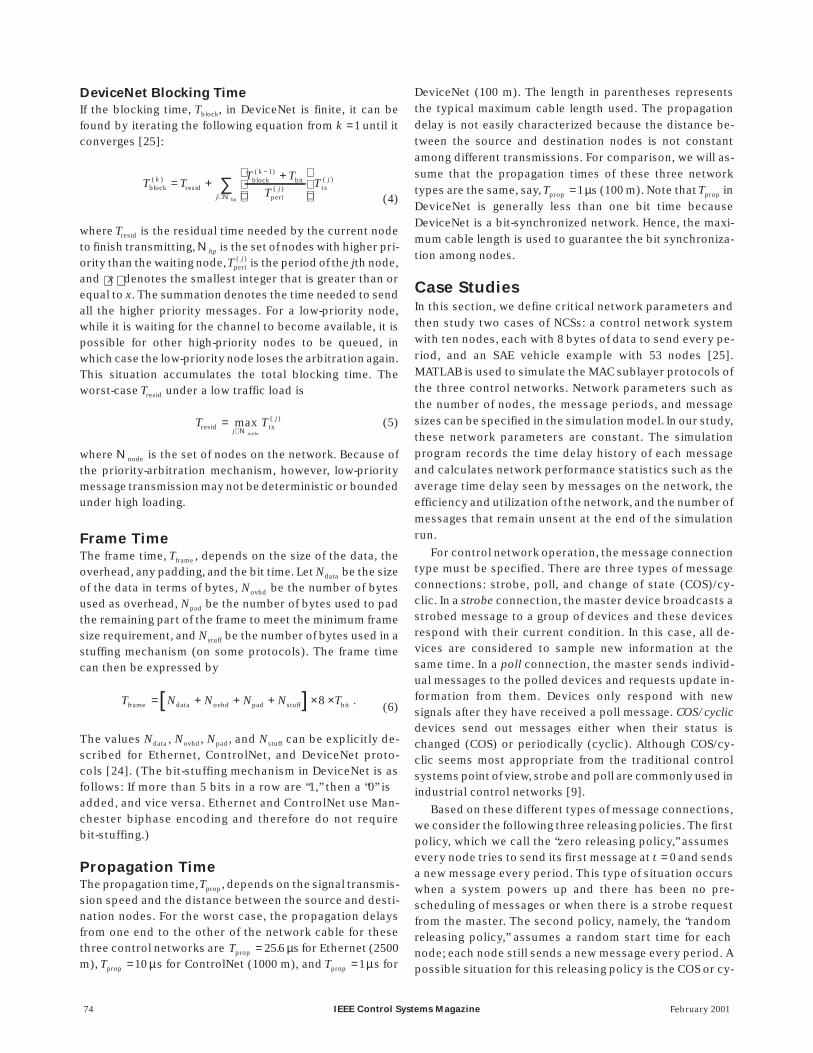
Case Study I: Ten Nodes, Equal PeriodsIn this case study of a network with ten nodes with equal pe-riods and data sizes, we examine nine different periods witha total simulation time of 0.5 s. The periods were chosenbased on the total time to send all ten messages over the dif-ferent networks; 576, 320, and 2200 µs for Ethernet,ControlNet, and DeviceNet, respectively. The three releas-ing policies (zero, random, scheduled) were also examined.The simulation results for a message period of 5000 µs aresummarized in Table 2 and Figs. 8-10.
When the message period is longer than the total mes-sage transmission time, the performance indexes are simi-lar for all three networks. Because of the different networkdata rates, however, the message period at which saturationoccurs is different for the three networks. When the periodis shorter than the total transmission time (i.e., the trafficload exceeds the availability of the network), the utilizationapproaches 100% and the time delay increases (it will be-come unbounded as the simulation time goes to infinity).Therefore, the network becomes unstable.
The average time delays for the three releasing policiesare shown in Fig. 8. The zero releasing policy has the longestaverage delay in every network because all nodes experi-ence contention when trying to send messages. Although
76 IEEE Control Systems Magazine February 2001
EthernetControlNetDeviceNet
1010
1010
1010
105
105
105
100
100
100
103
103
103
102
102
102
Zero Releasing Policy
Random Releasing Policy
Scheduled Releasing Policy
Ave
rage
Tim
e D
elay
(s)µ
Message Period ( s)µ
Figure 8. A comparison of the average time delay versus messageperiod (ten-node case).

February 2001 IEEE Control Systems Magazine 77
EthernetControlNetDeviceNet
103
103
103
102
102
102
101
101
101
Tim
e D
elay
(s)µ
104
104
104
0 20
20
20
40
40
40
60
60
60
80
80
80
100
100
100
Messages of Node 5
Messages of Node 10
Messages of Node 1
(a)
EthernetControlNetDeviceNet
103
103
103
102
102
102
101
101
101
Tim
e D
elay
(s)µ
104
104
104
0 20
20
20
40
40
40
60
60
60
80
80
80
100
100
100
Messages of Node 5
Messages of Node 10
Messages of Node 1
(b)
EthernetControlNetDeviceNet
103
103
103
102
102
102
101
101
101
Tim
e D
elay
(s)µ
104
104
104
0 20
20
20
40
40
40
60
60
60
80
80
80
100
100
100
Messages of Node 5
Messages of Node 10
Messages of Node 1
(c)
0
Figure 9. The time delay history of nodes one, five, and ten with a period of 5000 s and using the three releasing policies (ten-node case);(a) zero releasing policy, (b) random releasing policy, and (c) scheduled releasing policy.

the Ethernet data rate is much faster thanDeviceNet’s, the delays due to collisions andthe large required message size combine toincrease the average time delay for Ethernetin this case. For a typical random releasingpolicy, average time delays are reduced be-cause not all nodes try to send messages (orexperience network contention) at the sametime, although some contention still exists.The scheduled releasing policy makes thebest use of each individual network; the av-erage time delay of this releasing policy isonly the transmission time. When the net-works are not saturated, the average time de-lay is just equal to the frame time (i.e., thetime taken to transmit a message frame). Inthis case, all three networks maintain a con-stant time delay.
For the two deterministic control net-works (i.e., DeviceNet and ControlNet), if thenetwork is not saturated (i.e., Putil <100%),there are no messages queued at the buffer.For Ethernet, however, there are alwayssome messages queued at the buffer, and,moreover, some messages are discarded dueto the BEB algorithm. We also notice that theaverage time delay of each message is notconstant, even though the network is not sat-urated. The discarded messages andnonconstant time delay may make Ethernetunsuitable in this loading situation for con-trol applications.
Table 2 compares the performance of threereleasing policies for a message period of 5000µs. The network efficiency is low for the zeroand random releasing policies, but can reach100% in the scheduled releasing policy if thetraffic load is not saturated. With a messageperiod of 5000 µs, none of the networks is satu-rated, and the network utilizations ofControlNet and DeviceNet are the same for thethree releasing policies. For Ethernet, how-ever, the network utilization in the zero andrandom releasing policies is different from thatin the scheduled releasing policy becausethere are multiple transmissions for one mes-sage when messages collide.
Again using the 5000 µs period, we alsodemonstrate the time delay history of themessages sent by three different nodes on thenetwork (nodes 1, 5, and 10 in Fig. 9).DeviceNet is the only network that can guar-antee constant time delays for all three releas-ing policies; this is due to the priorityarbitration mechanism and the periodicity of
78 IEEE Control Systems Magazine February 2001
Tim
e D
elay
(s)µ
Tim
e D
elay
(s)µ
0
0
20
20
40
40
60
60
80
80
100
100
9000
700
8000
600
7000
500
6000
400
5000
300
4000
200
3000
100
2000
1000
0
0
Zero Releasing PolicyRandom Releasing PolicyScheduled Releasing PolicyEstimated Mean (1091)Mean + 2*STD (2896)
Message Number of Each Node (Period=5000 s)µ
Message Number of Each Node (Period=5000 s)µ
(a)
(b)
Zero Releasing PolicyRandom Releasing PolicyScheduled Releasing PolicyEstimated Max (472)Estimated Min (32)
Tim
e D
elay
(s)µ
0 20 40 60 80 100
3500
3000
2500
2000
1500
1000
500
0
Message Number of Each Node (Period=5000 s)µ(c)
Zero Releasing PolicyRandom Releasing PolicyScheduled Releasing PolicyEstimated Max (2442)Estimated Min (222)
Figure 10. Message time delay associated with three releasing policies (ten-nodecase). The estimated mean, maximum, and minimum values are computed from thenetwork analysis for the zero and scheduled releasing policies; (a) Ethernet, (b)ControlNet, and (c) DeviceNet.
messages. Hence, the qualitative performance of DeviceNetis independent of the releasing policy in this case (i.e., whenthe network is not saturated). As the traffic load increases(high frequency of messages), only higher priority nodes cangain access to the network and maintain bounded transmis-sion time delays, but low-priority messages cannot accessthe network and remain unsent. Using the scheduled and ran-dom releasing policies, the Ethernet message collision proba-bility is low at low message rates. Hence, Ethernet generallyhas a constant time delay in low traffic loads. When collisionsoccur as in the zero or random releasing policy, however, thetime delay is not constant and is difficult to predict, as shownin Fig. 9(a) and (b). Although ControlNet only exhibits a con-stant time delay under scheduled releasing policy condi-tions, it always guarantees a bounded time delay when thetraffic load is not saturated, no matter what the releasing pol-icy, as shown in Fig. 9.
The delays experienced by all the messages on the net-work are combined in Fig. 10. Again, with a message periodof 5000 µs, none of the networks is saturated. In Ethernet,shown in Fig. 10(a), the zero and random releasing policiesdemonstrate their nondeterministic time delays, eventhough the traffic load is not saturated. Fig. 10(b) shows thatthe message time delay of ControlNet is bounded for all re-leasing policies; we can estimate the lower and upperbounds based on the formulas derived in the timing analysissection. Due to the asynchronicity between the message pe-riod and the token rotation period, these time delays exhibita linear trend with respect to the message number. The sim-ulation results for DeviceNet, shown in Fig. 10(c), demon-strate that every node in DeviceNet has a constant timedelay that depends only on the message number. The esti-mated mean time delay (1091 µs) for Ethernet in Fig. 10(a) iscomputed for the case of the zero releasing policy from (2)
February 2001 IEEE Control Systems Magazine 79
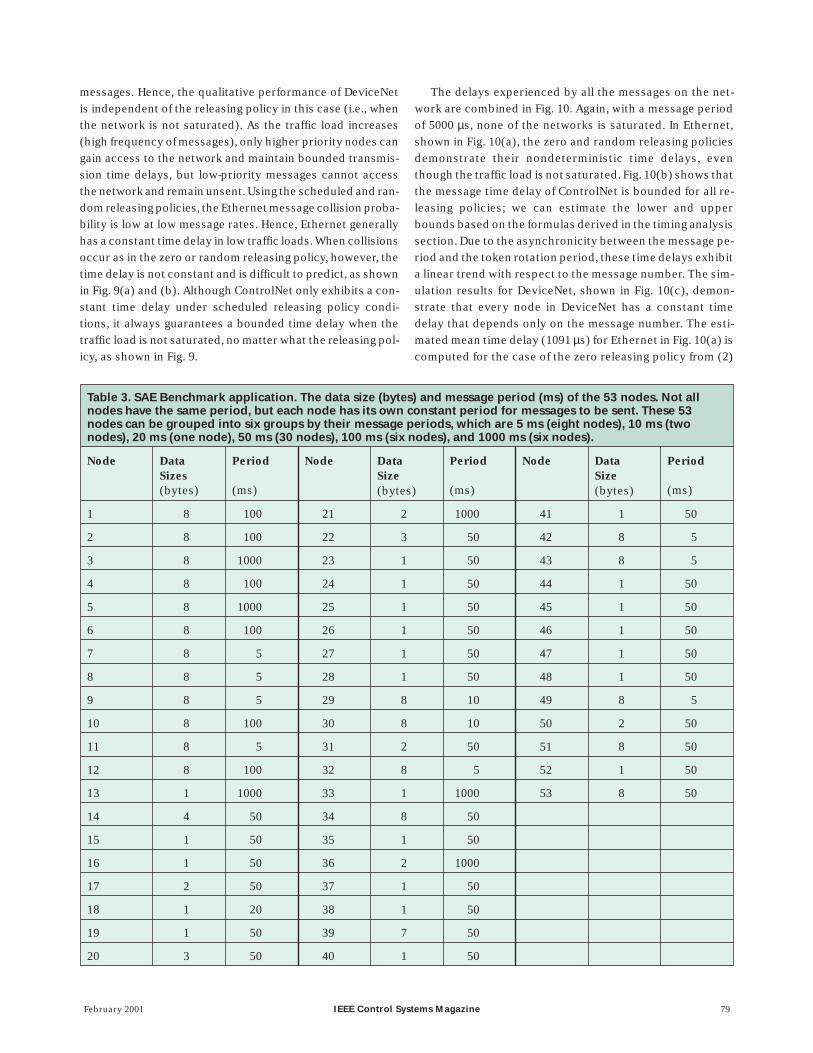
Table 3. SAE Benchmark application. The data size (bytes) and message period (ms) of the 53 nodes. Not allnodes have the same period, but each node has its own constant period for messages to be sent. These 53nodes can be grouped into six groups by their message periods, which are 5 ms (eight nodes), 10 ms (twonodes), 20 ms (one node), 50 ms (30 nodes), 100 ms (six nodes), and 1000 ms (six nodes).
Node DataSizes(bytes)
Period
(ms)
Node DataSize(bytes)
Period
(ms)
Node DataSize(bytes)
Period
(ms)
1 8 100 21 2 1000 41 1 50
2 8 100 22 3 50 42 8 5
3 8 1000 23 1 50 43 8 5
4 8 100 24 1 50 44 1 50
5 8 1000 25 1 50 45 1 50
6 8 100 26 1 50 46 1 50
7 8 5 27 1 50 47 1 50
8 8 5 28 1 50 48 1 50
9 8 5 29 8 10 49 8 5
10 8 100 30 8 10 50 2 50
11 8 5 31 2 50 51 8 50
12 8 100 32 8 5 52 1 50
13 1 1000 33 1 1000 53 8 50
14 4 50 34 8 50
15 1 50 35 1 50
16 1 50 36 2 1000
17 2 50 37 1 50
18 1 20 38 1 50
19 1 50 39 7 50
20 3 50 40 1 50

and a two standard deviation bound is also shown. This esti-mated value is close to the simulated value (1081 µs) givenin Table 2. The maximum and minimum time delays forControlNet and DeviceNet are computed from (3), (4), and(6).
Case Study II: SAE BenchmarkNext we consider a benchmark application from the SAE [25].We simulate the specified traffic flow on three control net-works. In this example, there are 53 nodes that belong toseven subsystems, namely: the batteries, the vehicle control-ler, the inverter/motor controller, the instrument panel dis-
play, the driver inputs, the brakes, andthe transmission control. Not all nodeshave the same period, but each nodehas its own constant period of messagesto be sent. Because the minimum dataelement in all three networks is 1 byte, amessage of 1 or 8 bits has the sametransmission time. To study the impactof data size on network performance, weincrease the data size at each node by afactor of eight (e.g., changing node 1from 8 bits in [25] to 8 bytes.) The datasize and period of each node areshown in Table 3. We also apply thethree releasing policies (zero, ran-dom, and scheduled) as discussed ear-lier. The total simulation time is 10 s. Thesimulation results are shown in Figs. 11and 12, and a summary is given in Table4.
Table 4 illustrates three cases basedon three different node numbering as-signments: the node numbering in Case Iis ordered based on the functionalgroups, and the other two cases are or-dered by message periods (Case II is de-creasing, and Case III is increasing). Notethat the total transmission times for all53 messages are 3052.8, 1366.4, and 8470µs in Ethernet, ControlNet, andDeviceNet, respectively.
Case I simulation results for thethree control networks are compared inFig. 11. For the zero releasing policy,Ethernet has the largest message timedelay value and standard deviationover all 53 nodes. This is due to the highprobability of message collision withthe zero releasing policy. ForDeviceNet, as expected, there is a lineartrend for message time delay over themessage node numbers. ForControlNet, however, the average mes-
sage time delay is nearly the same over all 53 nodes. This isbecause the MAC in ControlNet is based on the token rota-tion mechanism, and every node gains access to the net-work medium at a deterministic period. Fig. 11 also showslower and consistent variability of time delays forControlNet and DeviceNet compared to that for Ethernet.
For the random releasing policy, ControlNet still demon-strates a consistent time delay over all 53 nodes, but Ether-net and DeviceNet do not. For DeviceNet, however, nodeswith small node numbers still have a shorter message timedelay than nodes with large node numbers. The averagemessage time delays of the random releasing policy are
80 IEEE Control Systems Magazine February 2001
4
3
2
1
0
x 104
Zero Releasing Policy EthernetControlNetDeviceNet
0 10 20 30 40 50
0 10 20 30 40 50
5000
4000
3000
2000
1000
0
Tim
e D
elay
s (
s)µ
Random Releasing Policy
Scheduled Releasing Policy
0 10 20 30 40 50
5000
4000
3000
2000
1000
0
Node Number
Figure 11. Statistical demonstration of message time delay on three control networks forthe SAE example: node numbering by subsystem. Note: The symbols “ ,” “ ” and “ ”denote the message time delay means of Ethernet, ControlNet, and DeviceNet, respectively;the dashdot, dashed, and solid lines represent the amount of message time delay variancecomputed from the simulation result as twice the standard deviation of the time delay.

shorter than those of the zero releasing policy, as shown inTable 4. Ethernet still has high variability of time delay com-pared to ControlNet and DeviceNet.
For the scheduled releasing policy, Ethernet demon-strates outstanding results because of its high transmissionspeed and zero possibility of message collisions. Becausethe total transmission time of all 53 messages is 8470 µs inDeviceNet, the last few nodes with short message periods(e.g., nodes 39-53) have higher variability of message timedelays, especially nodes 39, 42, 43, and 49, which have largedata sizes and shorter message periods. The results forControlNet, however, are similar for all releasing policies.For multiperiod systems, ControlNet is less sensitive to thereleasing policies, and it is very difficult to coordinate thesystem parameters and maintain the minimum time delay,as we did in the ten-node simulation.
In this SAE example setting, shown in Table 3, there aresix different message periods. To study the effect of nodenumbering, we regroup these nodes by their message pe-riods. We first let those nodes with shorter message peri-ods have lower node numbers and find that the nodeswithin one group have similar performance for the Control-Net and DeviceNet systems but that performance variesbetween node groups. There is not much difference in per-
formance between node groups for Ethernet, however.Note that the simulation results within one group are simi-lar to the ten-node example we studied in the first part ofthis section.
Fig. 12 shows the time delay characteristics of two releas-ing policies in DeviceNet for three cases of node numbering.Because of the priority mechanism on node numbers, thetime delay profile exhibits a linear trend over node num-bers. There is little variance, however, for the case in whichmessages are ordered by increasing period in the zero re-leasing policy. This is because high-frequency nodes arehigh-priority nodes and have little difficulty accessing thenetwork medium. For the scheduled releasing policy, boththe average time delay and the variance are smaller than forthe zero releasing policy. The last few nodes of the decreas-ing message period numbering case have large time delayvariance with both releasing policies because they arelower priority nodes with high-frequency messages and al-ways lose the contention battle when one arises. The gapbetween nodes 33 and 34 is due to the fact that the totaltransmission time from nodes 1 to 33 is more than 5000 µsand node 34 always loses the contention to those nodeswith higher priority. A similar situation occurs betweennodes 51 and 52.
February 2001 IEEE Control Systems Magazine 81
Case I: Ordered by Subsystem Case I: Ordered by Subsystem
Case II: Ordered by Decreasing Message Period Case II: Ordered by Decreasing Message Period
Case III: Ordered by Increasing Message Period Case III: Ordered by Increasing Message Period
10000
5000
0
10000
5000
0
10000
5000
0
Tim
e D
elay
s (
s)µ
Tim
e D
elay
s (
s)µ
0
0
0
0
00
10
10
10
10
1010
20
20
20
20
2020
30
30
30
30
3030
40
40
40
40
4040
50
50
50
50
5050
5000
4000
3000
2000
1000
0
5000
4000
3000
2000
1000
0
5000
4000
3000
2000
1000
0
Node Number Node Number
(a) (b)
Figure 12. Statistical demonstration of message time delay on DeviceNet for the SAE example. Note: The symbol “ ” denotes themessage time delay mean; the solid lines represent the amount of message time delay variance computed from the simulation result as twicethe standard deviation of the time delay; (a) zero-releasing policy, (b) scheduled releasing policy.

Conclusions and Future WorkThe features of three candidate control networks—Ethernet(CSMA/CD), ControlNet (token bus), and DeviceNet(CAN)—were discussed in detail. We first described theMAC mechanisms of these protocols, which are responsiblefor satisfying both the time-critical/real-time response re-quirement over the network and the quality and reliability ofcommunication between devices on the network. Thesetiming parameters, which will ultimately influence controlapplications, are affected by the network data rate, the peri-ods of messages, the data or message size of the informa-tion, and the communication protocol. For each protocol,we studied the key performance parameters of the corre-sponding network when used in a control situation, includ-ing network utilization, magnitude of the expected timedelay, and characteristics of time delays. Simulation resultswere presented for several different scenarios. The timinganalyses and comparisons of message time delay given inthis article should be useful for designers of NCSs.
The evaluation study described here is based on the char-acteristics and requirements of control systems. The charac-teristics are small data sizes and periodic messages, and therequirements include guaranteed transmission and boundedtime delay. The suitability of network protocols for use incontrol systems is greatly influenced by these two criteria. Al-though Ethernet has seen widespread use in many data trans-mission applications and can support high data rates up to 1
Gb/s, it may not be suitable as the communication mediumfor some control systems when compared with deterministicnetwork systems. Because of its high data rate, however,Ethernet can be used for aperiodic/non-time-critical andlarge data size communication, such as communication be-tween workstations or machine cells. For machine- levelcommunication with controllers, sensors, and actuators,deterministic networks are generally more suitable formeeting the characteristics and requirements of controlsystems. For control systems with short and/or prioritizedmessages, DeviceNet demonstrates better performance. Thescheduled and unscheduled messaging capabilities inControlNet make it suitable for time-critical and non-time-critical messages. ControlNet is also suitable for large datasize message transmission.
Our future efforts will focus on controller design forNCSs, which can differ significantly from the design of tradi-tional centralized control systems. This work will includeconducting experimental studies of control networks forcontrol applications. We plan to use this analysis, along withthe performance evaluation of candidate control networkspresented here, as the basis for future message schedulingand control algorithm designs for NCSs.
AcknowledgmentsWe wish to acknowledge the contributions of J. Korsakas, thesupport of the National Science Foundation Engineering Re-
82 IEEE Control Systems Magazine February 2001
Table 4. Simulation results of SAE example: Three node numbering cases.
Node Numbering Case ISubsystem Ordering
Case IIDecreasing Message PeriodOrdering
Case IIIIncreasing Message PeriodOrdering
Releasing Policy Zero Rand. Sch’d Zero Rand. Sch’d Zero Rand. Sch’d
Average time delay ( s)
Ethernet 3268 122 58 3377 103 58 3362 80 58
ControlNet 558 417 439 555 406 458 562 407 444
DeviceNet 2176 428 453 2021 305 568 2202 253 386
Efficiency (%)
Ethernet 1.7 47.2 100.0 1.8 55.8 100.0 1.8 71.8 100.0
ControlNet 5.6 7.5 7.1 5.6 7.7 6.8 5.6 7.7 7.0
DeviceNet 9.1 46.2 43.7 9.8 64.8 34.8 9.0 78.1 51.2
Utilization (%)
Ethernet 47.6 16.6 14.5 47.5 16.3 14.5 47.5 15.4 14.5
ControlNet 7.9 7.9 7.9 7.9 7.9 7.9 7.9 7.9 7.9
DeviceNet 49.7 49.7 49.7 49.7 49.7 49.7 49.7 49.7 49.7

search Center for Reconfigurable Machining Systems at theUniversity of Michigan under grant EEC95-92125, the OpenDeviceNet Vendor Association, and ControlNet International.
References[1] L.H. Eccles, “A smart sensor bus for data acquisition,” Sensors, vol. 15, no.3, pp. 28-36, 1998.
[2] S. Biegacki and D. VanGompel, “The application of DeviceNet in processcontrol,” ISA Trans., vol. 35, no. 2, pp. 169-176, 1996.
[3] L.D. Gibson, “Autonomous control with peer-to-peer I/O networks,” Sen-sors, vol. 12, no. 9, pp. 83-90, Sept. 1995.
[4] A. Ray, “Introduction to networking for integrated control systems,” IEEEContr. Syst. Mag., vol. 9, pp. 76-79, Jan. 1989.
[5] G. Schickhuber and O. McCarthy, “Distributed fieldbus and control net -work systems,” Computing Contr. Eng., vol. 8, no. 1, pp. 21-32, Feb. 1997.
[6] D. Song, T. Divoux, and F. Lepage, “Design of the distributed architecture ofa machine-tool using FIP fieldbus,” in Proc. IEEE Int. Conf. Application SpecificSystems, Architectures, Processors, Los Alamitos, CA, 1996, pp. 250-260.
[7] R.S. Raji, “Smart networks for control,” IEEE Spectrum, vol. 31, pp. 49-55,June 1994.
[8] Y. Koren, Z.J. Pasek, A.G. Ulsoy, and U. Benchetrit, “Real-time open controlarchitectures and system performance,” CIRP Annals—Manuf. Technol., vol.45, no. 1, pp. 377-380, 1996.
[9] DeviceNet Specifications, 2nd. ed. Boca Raton, FL: Open DeviceNet Ven-dors Association, 1997.
[10] G. Cena, C. Demartini, and A. Valenzano, “On the performances of twopopular fieldbuses,” in Proc. IEEE Int. Workshop Factory Commun. Syst., Barce-lona, Spain, Oct. 1997, pp. 177-186.
[11] J.D. Wheelis, “Process control communications: Token Bus, CSMA/CD, orToken Ring?” ISA Trans., vol. 32, no. 2, pp. 193-198, July 1993.
[12] ControlNet Specifications, 2nd ed. Boca Raton, FL: ControlNet Interna-tional, 1998.
[13] S. Saad-Bouzefrane and F. Cottet, “A performance analysis of distributedhard real-time applications,” in Proc. IEEE Int. Workshop Factory Commun.Syst., Barcelona, Spain, Oct. 1997, pp. 167-176.
[14] S.A. Koubias and G.D. Papadopoulos, “Modern fieldbus communicationarchitectures for real-time industrial applications,” Comput. Ind., vol. 26, no.3, pp. 243-252, Aug. 1995.
[15] D. Bertsekas and R. Gallager, Data Networks, 2nd ed. Englewood Cliffs, NJ:Prentice-Hall, 1992.
[16] B.J. Casey, “Implementing Ethernet in the industrial environment,” inProc. IEEE Ind. Applicat. Soc. Ann. Meeting, vol. 2, Seattle, WA, Oct. 1990, pp.1469-1477.
[17] A.S. Tanenbaum, Computer Networks, 3rd ed. Upper Saddle River, NJ:Prentice-Hall, 1996.
[18] H. Bartlett and J. Harvey, “The modeling and simulation of a pick andplace computer-integrated manufacturing (CIM) cell,” Comput. Ind., vol. 26,no. 3, pp. 253-260, Aug. 1995.
[19] G. Paula, “Building a better fieldbus,” Mech. Eng., pp. 90-92, June 1997.
[20] V.K. Khanna and S. Singh, “An improved ‘piggyback Ethernet’ protocoland its analysis,” Comput. Networks ISDN Syst., vol. 26, no. 11, pp. 1437-1446,Aug. 1994.
[21] K.K. Ramakrishnan and H. Yang, “The Ethernet capture effect: Analysis
and solution,” in Proc. 19th Conf. Local Comp. Networks, Minneapolis, MN, Oct.
1994, pp. 228-240.
[22] J. Eidson and W. Cole, “Ethernet rules closed-loop system,” InTech, pp.
39-42, June 1998.
[23] J. Moyne, N. Najafi, D. Judd, and A. Stock, “Analysis of sensor/actuator
bus interoperability standard alternatives for semiconductor manufactur-
ing,” in Sensors Expo Conf. Proc., Cleveland, OH, Sept. 1994.
[24] F.-L. Lian, J. Moyne, and D.M. Tilbury., “Performance evaluation of con -
trol networks: Ethernet, ControlNet, and DeviceNet,“ Tech. Rep.
UM-MEAM-99-02, Feb. 1999. Available: http://www.eecs.umich.edu/~impact
[25] K. Tindell, A. Burns, and A.J. Wellings, “Calculating controller area net -
work (CAN) message response times,” Contr. Eng. Practice, vol. 3, no. 8, pp.
1163-1169, Aug. 1995.
[26] F.-L. Lian, J. Moyne, and D.M. Tilbury, “Control performance study of a
networked machining cell,” in Proc. American Control Conf., Chicago, IL, June
2000, pp. 2337-2341.
Feng-Li Lian received the B.S. degree in agricultural machin-ery engineering in 1992 and the M.S. degree in electrical engi-neering in 1994 from National Taiwan University and the M.S.degree in industrial and operations engineering in 1998 fromthe University of Michigan. Currently he is a Ph.D. student inthe Department of Mechanical Engineering at the Universityof Michigan. His areas of research include networked controlsystems, constrained flexible manipulators, and statisticalprocess control.
James Moyne received his B.S.E.E. and B.S.E. degrees inmath and his M.S.E.E. and Ph.D. degrees from the Universityof Michigan. Since 1992 he has been an Associate ResearchScientist in the Department of Electrical Engineering andComputer Science at the University of Michigan. He is alsoPresident and co-founder of MiTeX Solutions, Inc. His areasof research include advanced process control, databasetechnology, and sensor bus technology. He has written anumber of refereed publications in each of these areas. Healso holds a patent and is the author of several semiconduc-tor manufacturing standards.
Dawn M. Tilbury received the B.S. degree in electrical engi-neering summa cum laude from the University of Minnesotain 1989 and the M.S. and Ph.D. degrees in electrical engineer-ing and computer sciences from the University of California,Berkeley, in 1992 and 1994, respectively. Since 1995 she hasbeen an Assistant Professor in the Mechanical EngineeringDepartment at the University of Michigan, Ann Arbor. Shereceived an Undergraduate Computational Engineering andScience Award from the U.S. Department of Energy in 1995and the EDUCOM Medal (jointly with Prof. Messner) in 1997.Her research interests include trajectory planning for non-linear systems (including mobile robots), real-time distrib-uted control of mechanical systems, and logic control ofmanufacturing systems. She received an NSF CAREER awardin 1999. She is a member of the IEEE, ASME, and SWE.
February 2001 IEEE Control Systems Magazine 83