devicenet product overview - uniroma3
TRANSCRIPT
DeviceNet Product Overview

Publication DN-2.5 - February 1998 1
DeviceNet Product Overview
Introduction
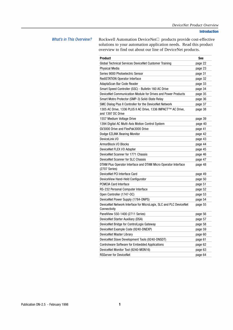
What’s in This Overview? Rockwell Automation DeviceNet products provide cost-effective solutions to your automation application needs. Read this product overview to find out about our line of DeviceNet products.
Product SeeGlobal Technical Services DeviceNet Customer Training page 22
Physical Media page 23
Series 9000 Photoelectric Sensor page 31
RediSTATION Operator Interface page 32
AdaptaScan Bar Code Reader page 33
Smart Speed Controller (SSC) - Bulletin 160 AC Drive page 34
DeviceNet Communication Module for Drives and Power Products page 35
Smart Motro Protector (SMP-3) Solid-State Relay page 36
SMC Dialog Plus II Controller for the DeviceNet Network page 37
1305 AC Drive, 1336 PLUS II AC Drive, 1336 IMPACT™ AC Drive, and 1397 DC Drive
page 38
1557 Medium Voltage Drive page 39
1394 Digital AC Multi-Axis Motion Control System page 40
GV3000 Drive and FlexPak3000 Drive page 41
Dodge EZLINK Bearing Monitor page 42
DeviceLink I/O page 43
ArmorBlock I/O Blocks page 44
DeviceNet FLEX I/O Adapter page 45
DeviceNet Scanner for 1771 Chassis page 46
DeviceNet Scanner for SLC Chassis page 47
DTAM Plus Operator Interface and DTAM Micro Operator Interface (2707 Series)
page 48
DeviceNet PCI Interface Card page 49
DeviceView Hand-Held Configurator page 50
PCMCIA Card Interface page 51
RS-232 Personal Computer Interface page 52
Open Controller (1747-OC) page 53
DeviceNet Power Supply (1784-DNPS) page 54
DeviceNet Network Interface for MicroLogix, SLC and PLC DeviceNet Connectivity
page 55
PanelView 550-1400 (2711 Series) page 56
DeviceNet Starter Auxiliary (DSA) page 57
DeviceNet Bridge for ControlLogix Gateway page 58
DeviceNet Example Code (9240-DNEXP) page 59
DeviceNet Master Library page 60
DeviceNet Slave Development Tools (9240-DNSDT) page 61
Controlware Software for Embedded Applications page 62
DeviceNet Monitor Tool (9240-MON16) page 63
RSServer for DeviceNet page 64

2 Publication DN-2.5 - February 1998
DeviceNet Product Overview
Introduction
About the DeviceNet Network The DeviceNet network connects low-level devices directly to plant-floor controllers without the need to hard-wire them to I/O modules. More than 300 vendors world-wide actively support the Open DeviceNet Vendor Association’s (ODVA) CAN-based network.
This 64-node, multidrop network allows you to use a single cable to interface devices up to 500m (1641ft) and beyond to your programmable controller rather than wiring each device to an I/O chassis. This all adds up to reduced wiring costs and a quicker installation setup.
"Intelligent" devices now can provide diagnostics – including predictive failure that can be used to reduce system downtime.
Why is the DeviceNet Network Betterthan Other Network Options?
The DeviceNet network is based on the Producer/Consumer network model, the latest in networking technology. Producer/Consumer makes control data accessible to every component of the operation simultaneously, making more efficient use of network bandwidth.
Producer/Consumer can dramatically reduce network traffic as it allows for change-of-state messaging, giving you faster response, and cyclic messaging, giving you greater determinism. Peer-to-peer messaging allows for data and status information exchange between devices. These benefits—faster response, greater determinism, increased flexibility/optimization—all yield higher productivity.
Publication DN-2.5 - February 1998 3
DeviceNet Product Overview
Introduction
Combining DeviceNet Features andRockwell Automation Innovation
The DeviceNet network is a cost-effective solution to low-level device networking and provides access to intelligence present in those devices. Rockwell Automation continues to bring you innovative solutions based on the most current technology. Accordingly, we bring you DeviceNet products that give you the ability to:
• know a Series 9000 photoelectric sensor is losing margin (possi-bly because of dust accumulation on the lens) before it fails to detect an object
• share look-up tables and I/O status among multiple AdaptaScan bar code readers
• monitor motor current draw, phase balance, and thermal capacity with the SMP-3 solid-state overload relay
• record historical bearing temperature and vibration with the EZLINK bearing monitor
• reduce your installation costs by decreasing the number of physical taps on the DeviceNet trunk line with DevicePort taps or DeviceBox taps
• eliminate additional enclosures and reduce installation time with ArmorBlock I/O blocks
• connect up to 128 discrete points using the FLEX I/O system and a single 1794-ADN adapter
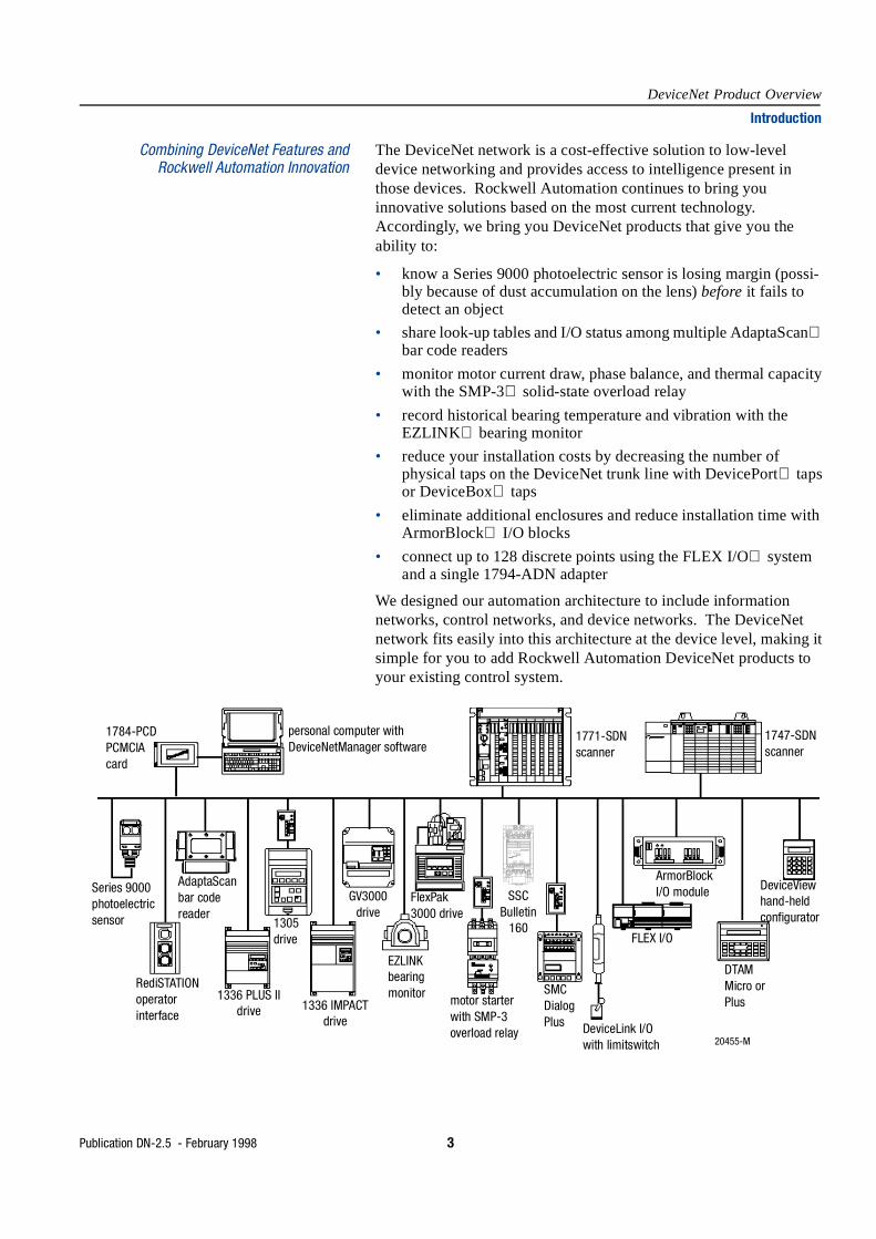
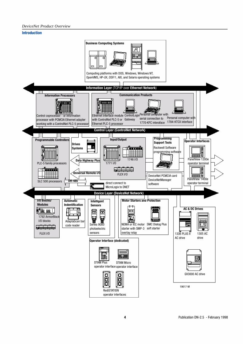
We designed our automation architecture to include information networks, control networks, and device networks. The DeviceNet network fits easily into this architecture at the device level, making it simple for you to add Rockwell Automation DeviceNet products to your existing control system.
1784-PCD PCMCIA card
personal computer with DeviceNetManager software
1771-SDN scanner
1747-SDN scanner
Series 9000 photoelectric sensor
RediSTATION operator interface
AdaptaScan bar code reader
1336 PLUS II drive
1305 drive
1336 IMPACT drive
GV3000 drive
EZLINK bearing monitor
FlexPak 3000 drive
motor starter with SMP-3 overload relay
SSC Bulletin
160
SMC Dialog Plus DeviceLink I/O
with limitswitch
FLEX I/O
ArmorBlock I/O module
DTAM Micro or Plus
DeviceView hand-held configurator
20455-M
L2S
L1R
L3T
BRÐ
BR+
1 2 3 4 5 6 7 8 9 10 11
T2V
TIU
T3W
ÐDC
+DC
FAULTREADY
DeviceNet
COMM
ª
4 Publication DN-2.5 - February 1998
DeviceNet Product Overview
Introduction
Business Computing Systems
Computing platforms with DOS, Windows, Windows NT, OpenVMS, HP-UX, OSF/1, AIX, and Solaris operating systems
Information Layer (TCP/IP over Ethernet Network)
Information Processors
Control coprocessor - or Information processor with PCMCIA Ethernet adapter working with a ControlNet PLC-5 processor
Communication Products
Ethernet interface module with ControlNet PLC-5 or Ethernet PLC-5 processor
ControlLogix Gateway
Personal computer with serial connection to 1770-KFC interaface
Personal computer with 1784-KTCX interface
Control Layer (ControlNet Network)
Programmable Controllers
PLC-5 family processors
SLC 500 processors
Drives Systems
Data Highway Plus
Universal Remote I/O
DH-485direct connect to MicroLogix to DNET
Input/Output
1771 I/O1746 I/O
FLEX I/O
Programming Support Tools
Rockwell Software programming software
DeviceNet PCMCIA card DeviceNetManager software
Operator Interfaces
PanelView 1200e operator terminal
PanelView 1400e operator terminal
Device Layer (DeviceNet Network)
I/O Blocks/Modules
1792 ArmorBlock I/O blocks
FLEX I/O
Automatic Indentification
AdaptaScan bar code reader
Intelligent Sensors
Series 9000 photoelectric sensors
Motor Starters and Protection
NEMA or IEC motor starter with SMP-3 overlay relay
SMC Dialog Plus soft starter
AC & DC Drives
1336 PLUS II AC drive
1305 AC drive
Operator Interface (dedicated)
DTAM Plus operator interface
DTAM Micro operator interface
RediSTATION operator interfaces
19617-M
GV3000 AC drive
Publication DN-2.5 - February 1998 5
DeviceNet Product Overview
Introduction
Integrating DeviceNetProducts with your Existing
Rockwell Automation Architecture
As a full-line supplier, we know that the function and cost of an integrated control system are dictated by how easily and effectively you can combine system components.
The DeviceNet network was designed to meet your needs. Rockwell Automation DeviceNet products increase flexibility and efficiency in your control system.
Integrate the industry’s fully open network with Allen-Bradley PLC scanners, SLC scanners, Series 9000 photoelectric sensors, and ac and dc drives, along with Reliance ac and dc drives and many other control products. Our DeviceNet products take advantage of this exciting new technology and provide access to your existing Rockwell Automation architecture.
Whether you’re using the ControlNet network, DH+ network, or Ethernet network, PLC processors, SLC processors, or other processors, Rockwell Automation DeviceNet products are easily integrated to help you link the plant floor with the rest of your control system.
Related PublicationsTitle Publication NumberDeviceNet System Overview DN-2.15
DeviceNet Cable System Planning and Installation Manual DN-6.7.2
6 Publication DN-2.5 - February 1998
DeviceNet Product Overview
Introduction
Rely on Rockwell Automation Qualityand World-Class Support
We have helped numerous customers around the world achieve their manufacturing goals. For assistance with Rockwell Automation DeviceNet products, call your local distributor or sales office.
Our support network offers complete system integration and support services including application engineering, installation supervision, system startup, training, field service, and ongoing product support.
We’re global because we’re local to you.
You can access a Rockwell Automation sales representative, appointed distributor, or authorized system integrator almost anywhere around the world. Perhaps that’s why Rockwell Automation is the preferred supplier of automation controls in the industry.

Publication DN-2.5 - February 1998 7
DeviceNet Product Overview
DeviceNet Technical Overview
What is DeviceNet? DeviceNet is a low-cost communications link to connect industrial devices (such as limit switches, photoelectric sensors, valve manifolds, motor starters, process sensors, bar code readers, variable frequency drives, panel displays and operator interfaces) to a network and eliminate expensive hardwiring.
The direct connectivity provides improved communication between devices as well as important device-level diagnostics not easily accessible or available through hardwired I/O interfaces,
DeviceNet is a simple, networking solution that reduces the cost and time to wire and install industrial automation devices, while providing interchangeability of like components from multiple vendors.
DeviceNet is an open network standard. The specification and protocol are open—vendors are not required to purchase hardware, software, or licensing rights to connect devices to a system. Anyone may obtain the DeviceNet Specification from the Open DeviceNet Vendor Association, Inc. (ODVA) for a nominal reproduction charge. Any company that manufactures DeviceNet products may join ODVA and participate in technical working groups that are developing enhancements to the DeviceNet Specification.
Buyers of the DeviceNet Specification receive an unlimited, royalty-free licence to develop DeviceNet products. Companies looking for assistance may purchase sample code that eases their implementation, development toolkits, and development services from many sources. The key hardware components are available from the largest worldwide suppliers of semiconductors.
Why the DeviceNet Communication Link?
For years the process industry has been attempting to develop a single, open standard to address all kinds of field devices. The original scope of their standards effort was aimed at replacing the 4-20 mA standard with a single digital standard. As the scope increased to address complex and sophisticated services (such as high data rate communications between controllers, time synchronization of large numbers of devices scanning at very high speeds), the development of a single standard became delayed.
8 Publication DN-2.5 - February 1998
DeviceNet Product Overview
DeviceNet Technical Overview
At the same time, the cost of communication technology has dropped considerably in recent years, making it cost-effective to connect simple devices never considered for SP50 fieldbus directly to a network. Such a standard for simple devices requires the same level of interchangeability as exists for 120/220 VAC and 24 VDX discrete, hardwired I/O. DeviceNet allows the interchangeability of simple devices while making interconnectivity for more complex devices possible. In addition to reading the state of discrete devices, DeviceNet provides the capability to report temperatures, to read the load current in a motor starter, to change the deceleration rate of drives, or to count the number of packages that have passed on a conveyor in the previous hour.
Controller Area Network (CAN) is the Key to Low Cost Products
The DeviceNet communication link is based on a broadcast-oriented, communications protocol—the Controller Area Network (CAN). The CAN protocol was originally developed by BOSCH for the European automatic market for replacing expensive, wire harnesses with low-cost network cable on automobiles. As a result, the CAN protocol has fast response and high reliability for applications as demanding as control of anti-lock brakes and air-bags. Chips are available in a variety of packages with high temperature ratings and high noise immunity, attributes well suited for the industrial automation market as well.
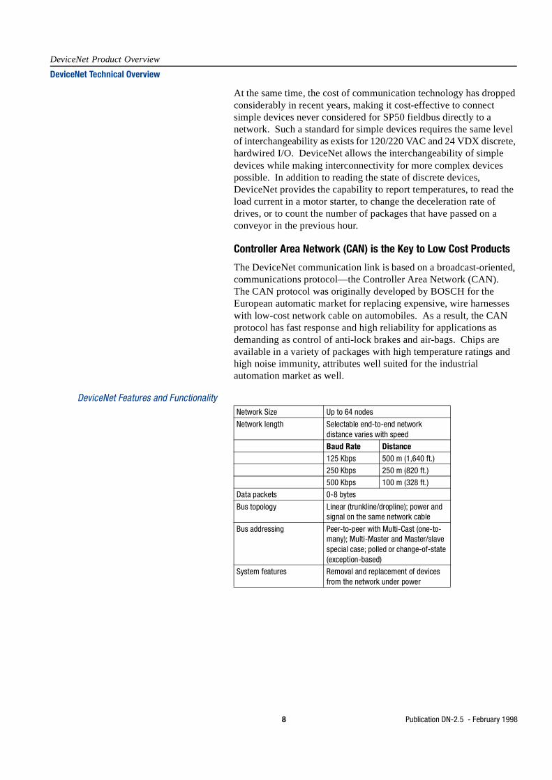
DeviceNet Features and FunctionalityNetwork Size Up to 64 nodes
Network length Selectable end-to-end network distance varies with speed
Baud Rate Distance125 Kbps 500 m (1,640 ft.)
250 Kbps 250 m (820 ft.)
500 Kbps 100 m (328 ft.)
Data packets 0-8 bytes
Bus topology Linear (trunkline/dropline); power and signal on the same network cable
Bus addressing Peer-to-peer with Multi-Cast (one-to-many); Multi-Master and Master/slave special case; polled or change-of-state (exception-based)
System features Removal and replacement of devices from the network under power
Publication DN-2.5 - February 1998 9
DeviceNet Product Overview
DeviceNet Technical Overview
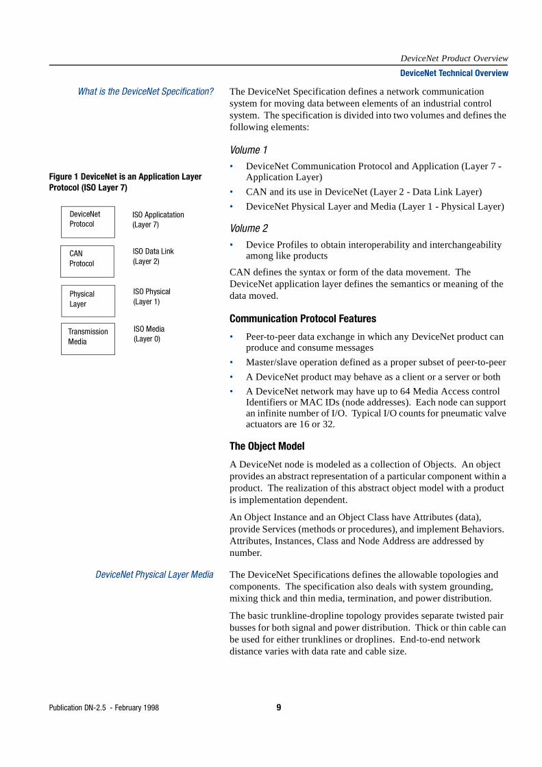
What is the DeviceNet Specification? The DeviceNet Specification defines a network communication system for moving data between elements of an industrial control system. The specification is divided into two volumes and defines the following elements:
Volume 1• DeviceNet Communication Protocol and Application (Layer 7 -
Application Layer)
• CAN and its use in DeviceNet (Layer 2 - Data Link Layer)
• DeviceNet Physical Layer and Media (Layer 1 - Physical Layer)
Volume 2• Device Profiles to obtain interoperability and interchangeability
among like products
CAN defines the syntax or form of the data movement. The DeviceNet application layer defines the semantics or meaning of the data moved.
Communication Protocol Features
• Peer-to-peer data exchange in which any DeviceNet product can produce and consume messages
• Master/slave operation defined as a proper subset of peer-to-peer
• A DeviceNet product may behave as a client or a server or both
• A DeviceNet network may have up to 64 Media Access control Identifiers or MAC IDs (node addresses). Each node can support an infinite number of I/O. Typical I/O counts for pneumatic valve actuators are 16 or 32.
The Object Model
A DeviceNet node is modeled as a collection of Objects. An object provides an abstract representation of a particular component within a product. The realization of this abstract object model with a product is implementation dependent.
An Object Instance and an Object Class have Attributes (data), provide Services (methods or procedures), and implement Behaviors. Attributes, Instances, Class and Node Address are addressed by number.
DeviceNet Physical Layer Media The DeviceNet Specifications defines the allowable topologies and components. The specification also deals with system grounding, mixing thick and thin media, termination, and power distribution.
The basic trunkline-dropline topology provides separate twisted pair busses for both signal and power distribution. Thick or thin cable can be used for either trunklines or droplines. End-to-end network distance varies with data rate and cable size.
Figure 1 DeviceNet is an Application Layer Protocol (ISO Layer 7)
DeviceNet Protocol
CAN Protocol
Physical Layer
Transmission Media
ISO Applicatation(Layer 7)
ISO Data Link(Layer 2)
ISO Physical(Layer 1)
ISO Media(Layer 0)
10 Publication DN-2.5 - February 1998
DeviceNet Product Overview
DeviceNet Technical Overview
Devices can be powered directly from the bus and communicate with each other using the same cable. Nodes can be removed or inserted from the network without powering-down the network.
Power taps can be added at any point in the network which makes redundant power supplies possible. The trunkline current rating is 8 amps. An opt-isolated design option allows externally powered devices, for example, ac drives starters and solenoid valves, to share the same bus cable. Other CAN-based networks allow only a single power supply, if at all, for the entire network.
Several different connector types can be used on DeviceNet. Both sealed and unsealed connectors are available. Large (mini-style) and small (micro-style) sizes of pluggable, sealed connectors are available. For products which do not require sealed connectors, open-style connectors can be used. Screw or clamp connections can be made directly to the cable if a pluggable connection is not required. The DeviceNet Specification also contains information on how to use these cable and connector components to construct single and multi-port taps.
Indicators and Configuration Switches Although DeviceNet does not require a product to have indicators, if a product does have indicators, it must adhere to the DeviceNet Specification. It is recommended that either a Module Status LED and a Network Status LED, or the combined Module Status/Network Status LED be included.
The indicator(s) consist of bi-color (green/red) LEDs which can have combinations of on, off or flashing. The Module Status LED indicates whether or not the device has power and is operating properly. The Network Status LED indicates the status of the communication link.
CAN and DeviceNet The Data Link Layer of DeviceNet is completely defined by the CAN specification and by the implementation of CAN Controller chips. The CAN specification defines two bus states called dominant and recessive. Any transmitter can drive the bus to a dominant state. The bus can only be in the recessive state when no transmitter is in the dominate state.
Several frame types are defined by CAN:
Data is moved on DeviceNet using the data frame. The other frames are either not used on DeviceNet or are for exception handling.
• data frame • remote frame• overload frame • error frame

Publication DN-2.5 - February 1998 11
DeviceNet Product Overview
DeviceNet Technical Overview
Higher Priority Data gets the Right-of-Way
DeviceNet is similar to Ethernet in that any DeviceNet node can attempt to transmit if the bus is quiet.
This provides inherent peer-to-peer capability. If two or more nodes try to access the network simultaneously, a bit-wise non-destructive arbitration mechanism resolves the potential conflict with no loss of data or bandwidth. By comparison, Ethernet uses collision detectors which result in loss of data and bandwidth as both nodes have to back-off and resend their data.
CAN uses a bit-wise arbitration method of collision resolution. All receivers on a CAN network synchronize to the transition form recessive to dominant represented by a bit. The identifier and the RTR (Remote Transmission Request) bit together form the Arbitration Field. The Arbitration Field is used to facilitate media access. Since DeviceNet does not use the RTR bit for any purpose it does not enter into bus access priority consideration. When a device transmits, it also monitors (receives) what it sends to make sure it is the same. This allows detection of simultaneous transmission. If a node transmitting a recessive bit receives a dominant bit while sending the Arbitration Field, it stops transmitting. The winner of an arbitration between two nodes transmitting simultaneously is the one with the lower numbered 11-bit identifier. CAN also specifies a data frame format with a 29-bit identifier field which is not used by DeviceNet.
The Control Field contains two fixed bits and a 4-bit length field. The length may be any number from 0 to 8 representing the number of bytes in the Data Field. The 0-8 byte size is ideal for low-end devices with small amounts of I/O data that must be exchanged frequently. And, at eight bytes, there is enough flexibility for simple devices to send diagnostic data, or to send a speed reference and acceleration rate to a drive.
InterframeSpace
1bit
1bit
1bit
1bit
1bit
11bits
6bits
0 .. 8bytes
15bits
>=3bits
7bits
Star
t of F
ram
e
Iden
tifie
r RTR
Bit
Cont
rol F
ield
Data
Fie
ld
CRC
Sequ
ence
CRC
Delim
iter
Ack
Slot
Ack
Delim
iter
End
of F
ram
e
Inte
rfram
eSp
ace
Figure 2 CAN Data Frame
}
Arbitration Field
CAN uses a unique, non-destructive bit-wise arbitration mechanism. This CAN-specific feature allows resolution of collisions (determination of a “winner”) without loss of throughput or resending of data by the higher priority node.
12 Publication DN-2.5 - February 1998
DeviceNet Product Overview
DeviceNet Technical Overview
The CRC field is a cyclic redundancy check word which is used by CAN controllers to detect frame errors. It is computed from the bits that come before it. A dominant bit in the ACK slot means at least one receiver besides the transmitter heard the transmission.
CAN uses several types of error detection and fault confinement methods including CRC and automatic retries. These methods, which are mostly transparent to the application, prevent a faulty node from disrupting the network.
CAN References 1. Anonymous, MC68HC05X4 HCMOS Microcomputer Unit, Motorolla LTD., 1992
2. Terry, K., Software Driver Routines for the Motorola MC68C05 CAN Module (AN464), Motorola LTD., 1993
3. Anonymous, 80c51 - Based 8-bit Microcontrollers, Data handbook IC20, Philips, 1995
4. Anonymous, 82527 Serial Communication Controller architectural Overview, Intel Corporation, February, 1995, Order Number: 272410-002
5. Anonymous, 8227 Serial Communications Controller, Controller Area Network Protocol, Intel Corporation, December, 1995 Order Number: 272250-006
6. Anonymous, 87C196CA/87C196CB Advanced 16-bit CHMOS Micorcontroller with Integrated CAN 2.0, Intel Corporation, October, 1993, Order Number; 272405-002
7. BOSCH CAN Specification—Version 2.0, Part A. 1991, Robert Bosch GmbH
8. ISO 11898: 1993 - Road vehicles - Interchange of digital information - Controller area network (CAN) for high-speed communication

Publication DN-2.5 - February 1998 13
DeviceNet Product Overview
DeviceNet Technical Overview
Communication Protocol and Application Applications using DeviceNet combine standard or application specific objects together into Device Profiles. The Device Profile fully defines the device as viewed from the network. A library of objects and Device Profiles is contained in the DeviceNet Specifications. ODVA coordinates the work of industry experts in the development of both new Object and Device Profile Specifications. This is done through Special Interest Groups (SIGs).
DeviceNet supports strobed, polled, cyclic, change-of-state, and application-triggered data movement. The user can choose master/slave, multi-master and peer-to-peer, or a combination configuration depending on device capability and application requirements. The choice of data movement can significantly speed up system response time. One popular application for DeviceNet is to use a standard, pre-defined set of connections which allow devices to operate in a Master/Slave Connection Set.
Connections
The DeviceNet Communication Protocol is based on the idea of connections. You must establish a connection with a device in order to exchange information with that device.
To establish a connection, each DeviceNet product will implement either an Unconnected Message Manager (UCMM) or an Unconnected Port. Both perform their function by reserving some of the available CAN identifiers.
When either the UCMM or the Unconnected Port is used to establish an Explicit Messaging Connection, that connection is then used to move information from one node to the other, or to establish additional I/O connections. Once connections have been established, I/O data may be moved among devices on the network. At this point, all the protocol of the DeviceNet I/O message is contained within the 11-bit CAN identifier. Everything else is data.
The 11-bit CAN identifier is used to define the connection ID. DeviceNet divides the 11-bit CAN identifier into four groups. The first three defined groups contain two fields—one 6-bit field for MAC ID and the other for Message ID. The combined fields define the connection ID.
14 Publication DN-2.5 - February 1998
DeviceNet Product Overview
DeviceNet Technical Overview
Devices may be clients or servers or both. Clients and servers may be producers, consumers or both. In a typical client device, its connection would produce requests and consume responses. In a typical server device, its connections would consume requests and produce responses. DeviceNet provides for several variations on this model. Some connections in either a client or a server may only consume messages. These connections would be the destination for cyclic or change-of-state messages. Similarly, some connections in either a client or server may only produce messages. These connections would be the source for cyclic or change-of-State messages. The use of cyclic or change-of-State connections can substantially reduce bandwidth requirements.
By design, nodes in a DeviceNet system are responsible for managing their own identifiers. These identifiers are distributed throughout the entire range. All nodes have a full range of message priorities available to them regardless of their MAC ID. Through the duplicate MAC ID algorithm, the uniqueness of CAN identifiers is guaranteed without the need for a central tool or record for each network.
A related issue is detection of duplicate nodes. Because DeviceNet uses a device address inside the CAN Identifiers Field, it presents a mechanism for detecting duplicate addressed devices. Preventing duplicate addresses is better than trying to locate them after they occur—something not taken into account in other CAN-based networks.
Another key benefit to nodes managing their identifiers is that a user can add and delete nodes and add additional peer-to-peer messages among existing nodes at any time without having knowledge of the existing set-up. No centralized record must be located or reconstructed. Since nodes know which IDs are already in use, a tool simply has to request an I/O connection be added between the two devices, specifying priority level, the data path, and the production trigger.
Publication DN-2.5 - February 1998 15
DeviceNet Product Overview
DeviceNet Technical Overview
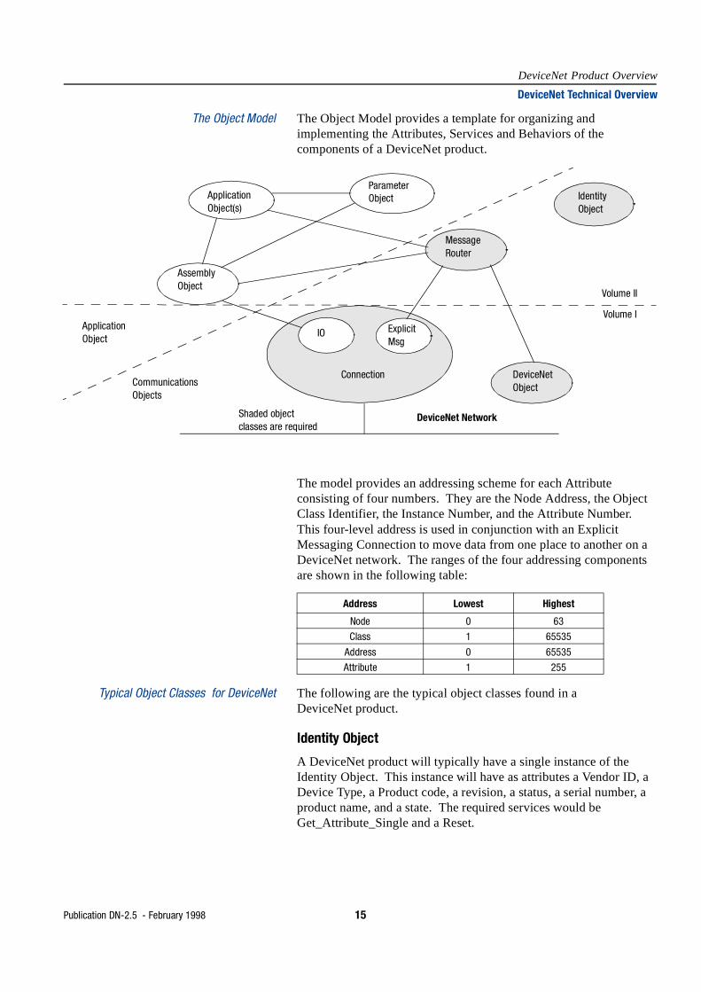
The Object Model The Object Model provides a template for organizing and implementing the Attributes, Services and Behaviors of the components of a DeviceNet product.
The model provides an addressing scheme for each Attribute consisting of four numbers. They are the Node Address, the Object Class Identifier, the Instance Number, and the Attribute Number. This four-level address is used in conjunction with an Explicit Messaging Connection to move data from one place to another on a DeviceNet network. The ranges of the four addressing components are shown in the following table:
Typical Object Classes for DeviceNet The following are the typical object classes found in a DeviceNet product.
Identity Object
A DeviceNet product will typically have a single instance of the Identity Object. This instance will have as attributes a Vendor ID, a Device Type, a Product code, a revision, a status, a serial number, a product name, and a state. The required services would be Get_Attribute_Single and a Reset.
ApplicationObject(s)
ParameterObject
MessageRouter
IdentityObject
AssemblyObject
IO ExplicitMsg
DeviceNetObject
Connection
ApplicationObject
CommunicationsObjects
Shaded objectclasses are required
DeviceNet Network
Volume II
Volume I
Address Lowest Highest
Node 0 63
Class 1 65535
Address 0 65535
Attribute 1 255

16 Publication DN-2.5 - February 1998
DeviceNet Product Overview
DeviceNet Technical Overview
Message Router Object
A DeviceNet product will typically have a single instance of the Message Router Object. The Message Router Object is the component of a product that passes Explicit Messages to the other Objects. It generally does not have any external visibility over the DeviceNet network.
DeviceNet Object
A DeviceNet product will typically have a single instance of the DeviceNet Object. This instance would have as attributes: Node, Address, or MAC ID, baud rate, Bus-Off action, Bus-Off counter, the allocation choice, and the master’s MAC ID. The only required service is Get_Attribute_Single.
Assembly Object(s)
A DeviceNet product will typically have one or more optional Assembly Objects. The primary purpose of these objects is to group different Attributes (data) from different application objects into a single Attribute which can be moved with a single message.
Connection Objects
A DeviceNet product will typically have at least two connection objects. Each connection object represents one end point of a virtual connection between two nodes on a DeviceNet network. These two types of connections are called Explicit Messaging and I/O Messaging. Explicit Messages contain Attribute addressing, Attribute values and a Service Code describing the desired action. I/O messages contain nothing but data. In an I/O message, all the information about what to do with the data is contained in the Connection Object associated with that I/O message.
Parameter Object
The optional Parameter object would be used in devices with configurable parameters. One instance would be presented for each configurable parameter. The Parameter object provides a standard way for a configuration tool to access all parameters. Configuration options which are attributes of the Parameter object could include values, ranges, text strings, and limits.
Application Objects
Usually at least one application object besides those from the Assembly or Parameter Class will be present in a device. There are a number of standard objects in the DeviceNet Object Library.
Messaging The DeviceNet application layer defines how identifiers are assigned (thus controlling priorities), and how the CAN data field is used to specify services, move data, and determine its meaning.

Publication DN-2.5 - February 1998 17
DeviceNet Product Overview
DeviceNet Technical Overview
The way information flows on a communication network is critical. Older communication technology consisted of messages that were constructed with a specific source and destination. Instead of a traditional source-destination approach, DeviceNet uses a more efficient Product-Consumer Model which requires packets to have identifier fields for data. The identifier provides the means for multiple priority levels (used in arbitration), more efficient transfer of I/O data, and multiple consumers.
The device with data produces the data on the network with proper identifier. All devices who needed data listen for messages. When devices recognize the appropriate identifier, they consume the data. With the Producer-Consumer Model, the message is no longer specific to a particular source or destination. A single message from one controller can be used by multiple motor starters using less bandwidth.
DeviceNet defines two different types of messaging.
• I/O Messaging
• Explicit Messaging
I/O Messages are for time-critical, control-oriented data. They provide a dedicated, special-purpose communication path between a producing application and one or more consuming applications. They are exchanged across single or multi-cast connectors and typically use high priority identifiers. I/O messages contain a protocol in the 8-byte data field. The only exception is for fragmented I/O messages where one byte is used for fragmentation protocol. The meaning of the message is implied by the connection ID (CAN identifier). Before messages are sent using these IDs, both the device sending and receiving them must be configured. The configuration contains the source and destination object attribute addresses for the producer and consumer of the data.
Explicit Messages provide multi-purpose, point-to-point communication paths between two devices. They provide the typical request/response-oriented network communications used to perform node configuration and problem diagnosis. Explicit Messages typically use low priority identifiers and contain the specific meaning of the message right in the data field. This includes the service to be performed and the specific object attribute address.
Fragmentation services are provided for messages that are longer then 8 bytes. Each I/O Message fragment incurs only a single byte of protocol overhead. There is no limit on the number of fragments. Fragmentation is also defined for explicit messaging. This flexibility assures that as more sophisticated devices are introduced and more capabilities are designed into devices, they can be added to existing DeviceNet networks. With its object-oriented design and addressing scheme, DeviceNet is unlimited in its ability to expand without having to alter the basic protocol and connection model.
18 Publication DN-2.5 - February 1998
DeviceNet Product Overview
DeviceNet Technical Overview
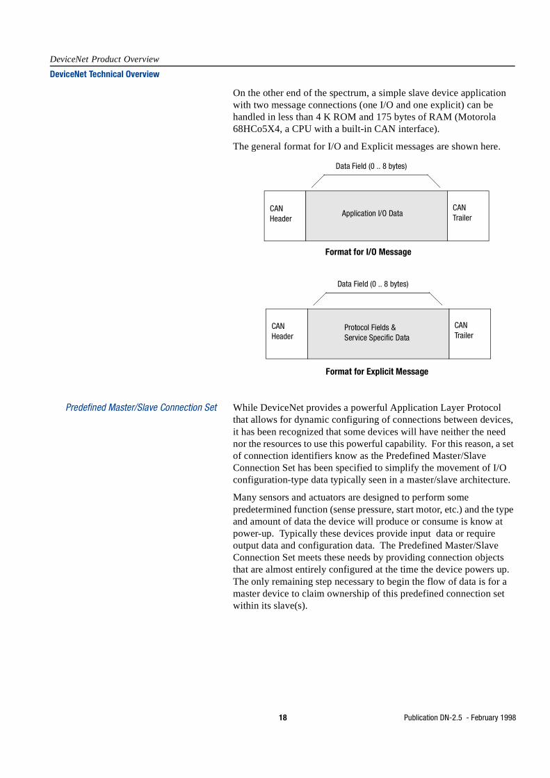
On the other end of the spectrum, a simple slave device application with two message connections (one I/O and one explicit) can be handled in less than 4 K ROM and 175 bytes of RAM (Motorola 68HCo5X4, a CPU with a built-in CAN interface).
The general format for I/O and Explicit messages are shown here.
Predefined Master/Slave Connection Set While DeviceNet provides a powerful Application Layer Protocol that allows for dynamic configuring of connections between devices, it has been recognized that some devices will have neither the need nor the resources to use this powerful capability. For this reason, a set of connection identifiers know as the Predefined Master/Slave Connection Set has been specified to simplify the movement of I/O configuration-type data typically seen in a master/slave architecture.
Many sensors and actuators are designed to perform some predetermined function (sense pressure, start motor, etc.) and the type and amount of data the device will produce or consume is know at power-up. Typically these devices provide input data or require output data and configuration data. The Predefined Master/Slave Connection Set meets these needs by providing connection objects that are almost entirely configured at the time the device powers up. The only remaining step necessary to begin the flow of data is for a master device to claim ownership of this predefined connection set within its slave(s).
Application I/O DataCANHeader
CANTrailer
Data Field (0 .. 8 bytes)
Format for I/O Message
Protocol Fields &Service Specific Data
CANHeader
CANTrailer
Data Field (0 .. 8 bytes)
Format for Explicit Message

Publication DN-2.5 - February 1998 19
DeviceNet Product Overview
DeviceNet Technical Overview
Message Group 2 is used for the definition of these identifiers. One noticeable difference in Group 2 is that the MAC ID is not specified as Source MAC ID. This allows the use of the Destination ID. There are strict rules about the use of this kind of connection to prevent duplicate CAN identifiers on the bus. The use of Destination ID allows devices which are centralized and which must communicate with many nodes (a master) to borrow identifiers from those nodes. In addition, the MAC ID and Message ID fields are reversed. This allows the Group ID and MAC ID to fall within the most significant 8 bits of the CAN identifier. This is important because many low-cost, 8-bit CAN chips can hardware filter only the first 8 bits. The exclusive use of Destination MAC ID further allows devices to take advantage of hardware filtering. Another important benefit is that the establishment of connections from the Predefined Set is simplified considerably. Only a few messages are required to have I/O connections up and running. The Predefined Set contains one explicit messaging connection and allows several different I/O connections including:
• bit Strobed Command/Response
• polled Command/Response
• change-of-State
• cyclic
Change-of-State and Cyclic Transmission
With change-of-state, a device produces its data only when it changes. To be sure the consuming device knows that the producer is still alive and active, DeviceNet provides an adjustable, background heartbeat rate. Devices send data whenever they change or the heartbeat timer expires. This keeps the connection alive and lets the consumer know the data source has not faulted. The minimum time on the heartbeat prevents inherently noisy nodes from dominating the network. By having the device generate the heartbeat, the controller is not burdened with having to send a nuisance request periodically just to make sure it is alive. This becomes even more efficient in the multicast case.
The cyclic option can reduce unnecessary traffic and packet processing. Instead of a temperature or analog input block being scanned dozens of time each second, it can be set up to report its data on a regular basis consistent with the rate of change it can detect. A temperature sensor on a slow PID loop with a 500 ms update time could have its cyclic rate set to 500 ms. Not only would this preserve bandwidth for more rapidly changing critical I/O data, it would also be more accurate as well. For example, it might be scanned once every 30 ms as part of a large scan list with many bytes of data per node on a heavily loaded master. This means that data used in a PID calculation might have been sampled anywhere from 470 to 530 ms. With cyclic production you know that the data samples will be at precisely 500 ms.

20 Publication DN-2.5 - February 1998
DeviceNet Product Overview
DeviceNet Technical Overview
By default, both change-of-state and cyclic are acknowledged exchanges (ACKs) so that the producer knows its intended consumer(s) received the data. For applications where change-of-state or cyclic rates are extremely fast, it make no sense to clutter up the network with ACK packets. Unnecessary ACKs can be suppressed with the Acknowledge Handler Object.
Now, even simple slave nodes can be set up to report at the most appropriate interval, whether that be cyclic or change-of-state. With the ACK Handler Object it is possible to have multiple consumers of the slaves’ data, not just the master. This multicast is especially useful for operator interface (OI) devices which can just listen for the data they needs, whether it is for display, alarm monitoring or data logging.
For alarm monitoring, it is important that a change-of-state not be missed, so the OI device would be included in the device’s ACK list, assuring a retry (or several retries) if for some reason the OI missed the message. On the other hand, if it was primarily a data collection device logging values every 5 seconds (and the node is producing values every 300 ms for control purposes), you would not have the logger set to ACK. If the logger misses a value, it can grab the next one 300 ms later.
Cyclic and change-of-state from the master are defined and selectable on a per node basis.
Device Profiles The DeviceNet specification goes beyond a physical connection protocol specification. It promotes interoperability by defining standard device models. All devices of the same model must support common identity and communication status data. Device-specific data is contained in device profiles that are defined for various device types. Simple devices form multiple vendors that comply with their device type profile will be logically interchangeable.
A device profile will contain the following sections:
• Definition of the device’s object model - This often contains a drawing like the one shown on page 15. Usually there are tables which list all of the object classes present in the device, the number of instances in each class, how each object effects behavior, and the public interfaces to each object.
• Definition of the device’s I/O data format - This usually includes definition of Assembly Object definition which contains the address (class, instance, and attribute) of the desired data components.
• Definition of the device’s configurable parameter and public interfaces to those parameters. This information is contained in an Electronic Data Sheet (EDS) which is included with the device’s user documentation.