international journal of civil engineering … and... · international journal of civil engineering...
TRANSCRIPT

International Journal of Civil Engineering and Technology (IJCIET), ISSN 0976 – 6308
(Print), ISSN 0976 – 6316(Online) Volume 4, Issue 3, May - June (2013), © IAEME
197
ANALYSIS AND DESIGN OF THREE LEGGED 400KV DOUBLE
CIRCUIT STEEL TRANSMISSION LINE TOWERS
Umesh S. Salunkhe1
and Yuwaraj M. Ghugal2
1 Department of Civil Engineering, Shreeyash College of Engineering & Technology, Satara
Tanda Parisar, Plot No 258, Aurangabad-431005, MH. 2Department of Applied Mechanics, Government College of Engineering, Karad, MH.
ABSTRACT
Transmission line towers constitute about 28 to 42 percent of the cost of the
transmission line. The increasing demand for electrical energy can be met more economically
by developing different light weight configurations of transmission line towers. The present
work describes the analysis and design of three legged self-supporting 400 kV double circuit
steel transmission line towers models with an angle and tube sections. In this study constant
loading parameters including wind forces as per IS: 802 (1995) are taken into account in both
models. The efforts have been made to do 3D analysis of tower considering all the members
of the space truss as primary members. STAAD. Pro program has been used to analysis and
design the members of 400 kV double circuit tower have deviation angle 2 degree. The
maximum sag and tension calculations of conductor and ground wire as per IS: 5613 (Part 3/
Sec 1) 1989. The comparative study is presented here with respective to axial forces,
deflections, maximum sectional properties, critical loading conditions between both models
of towers. The study shows that tower with tube sections are efficient and have better force –
weight ratio including 20.6% saving in weight of steel with tubes against steel with angles in
three legged transmission line tower.
Keywords: Three Legged, Broken Wire Condition, Sag, Angle Sections, Tube (Hollow
Rectangular) Sections.
1. INTRODUCTION
Transmission line towers constitute about 28 to 42 percent of the cost of the
transmission line [1]. The increasing demand for electrical energy can be met more
economically by developing different light weight configurations of transmission line towers
[2]. The selection of an optimum outline together with right type of bracing system, height,
cross arm type and other parameters contributes to a large extent in developing an economical
INTERNATIONAL JOURNAL OF CIVIL ENGINEERING AND
TECHNOLOGY (IJCIET)
ISSN 0976 – 6308 (Print)
ISSN 0976 – 6316(Online)
Volume 4, Issue 3, May - June (2013), pp. 197-209
© IAEME: www.iaeme.com/ijciet.asp
Journal Impact Factor (2013): 5.3277 (Calculated by GISI)
www.jifactor.com
IJCIET
© IAEME

International Journal of Civil Engineering and Technology (IJCIET), ISSN 0976 – 6308
(Print), ISSN 0976 – 6316(Online) Volume 4, Issue 3, May - June (2013), © IAEME
198
design of transmission line tower [3, 4]. As a goal of every designer are to design the best
(optimum) systems. But, because of the practical restrictions this has been achieved through
intuition, experience and repeated trials [5].
1.1. Transmission Line Tower Transmission line towers are used for supporting the high current or Extra High
Voltage electric transmission lines. This is simultaneously given rise to the need for relatively
large supporting structures. The structure engineer is entrusted with the challenging job of
designing and constructing transmission structures to support heavy conductor loads in open
weather with high degree of reliability and safety to the general public ensuring satisfactory
serviceability [6].
1.2. Three Legged Tower Generally four legged lattice towers are most commonly used as a transmission line
towers. Three legged towers only used as telecommunication, microwaves, radio and guyed
towers but not used in power sectors as a transmission line towers. The configurations of
three legged transmission line towers are very difficult because of cross arms and support
arrangement not easily and perfectly possible [7]. The axial forces and deflection are
increased in three legged tower components as compared four legged tower components but
saving in steel weight of 21.2% resulted when using a three legged tower as compared with a
four legged towers [8].
2. DESCRIPTION OF TOWER CONFIGURATION
For the present study, 400 kV double circuit steel transmission line with a suspension
towers (20
angle deviation) two models are considered. The first model of tower is triangular
base (three legged) self supporting type with angle sections. Thus, for optimizing the existing
geometry, one of these suspension tower is replaced by triangular base self supporting tower
with tube sections (hollow rectangular sections). The perception of the three legged
transmission line top view is shown in figure 1. The tower configurations are given in table 1
and figure 2. The plan and isometric view of triangular base tower models in STAAD. Pro
software is given in figure 3.
As per the guidelines of IS 802 and HVPNL [9], table 2 lists the details of some
parameters typical to a 400 kV double circuit suspension type tower and table 3 lists the
details of parameters for conductor and ground wire are considered from IS: 802 (Part 1/ Sec
1) 1995 and IS: 5613 (Part 3/ Sec 1) 1989.
Fig. 1: Transmission line layouts for triangular lattice tower

International Journal of Civil Engineering and Technology (IJCIET), ISSN 0976 – 6308
(Print), ISSN 0976 – 6316(Online) Volume 4, Issue 3, May - June (2013), © IAEME
199
3. MODELING APPROACH
The general package STAAD. Pro2008 has been used for the analysis and design. In
this study, 3D analysis of tower considering all the members of the space truss as primary
member has been used in STAAD. Pro programmed [7, 8]. The right and optimum selection
of configuration of the tower the sag and tension calculated as per 5613 (Part 2/ Sec 1) 1989
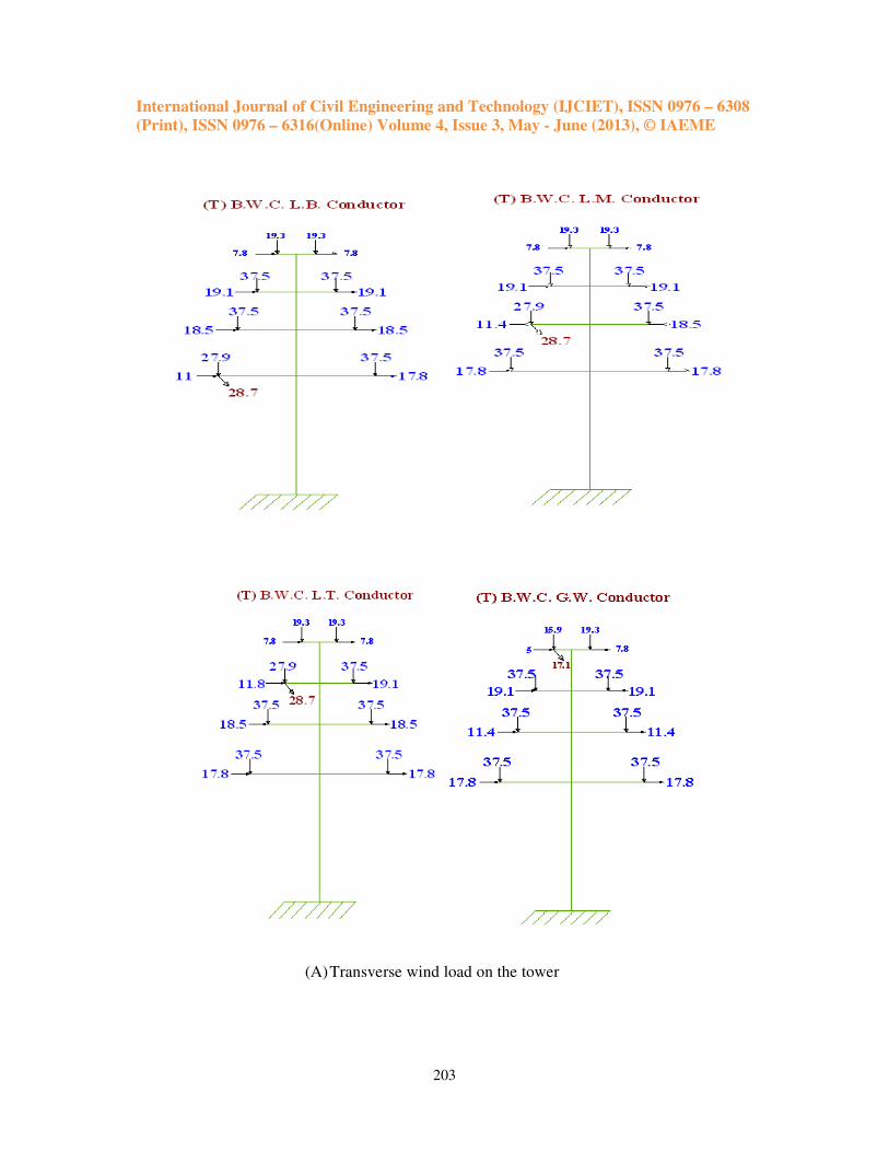
as given in table 4. The load and loading combinations criteria on the ground wire, conductor
and the towers are found using IS: 802. The loading calculations on tower due to conductor
and ground wire in normal condition (NC) as well as broken wire condition (BWC)
considering transverse as well as longitudinal direction wind as specified in table 5 and
shown in figure 4.
Fig. 2: Configuration of three and four legged towers

International Journal of Civil Engineering and Technology (IJCIET), ISSN 0976 – 6308
(Print), ISSN 0976 – 6316(Online) Volume 4, Issue 3, May - June (2013), © IAEME
200
Table 1: Configuration of Three and Four Legged Towers
Configuration Triangular Tower
(mm) Configuration
Triangular
Tower (mm)
Base width
Equilateral triangle
8500mm side
dimension
Max. Sag of conductor
(sag at min. temperature
and 36% WL)
13950
Cage bottom width
Equilateral triangle
3600mm side
dimension
Max. sag of ground wire
(sag at min. temperature
and 36% WL)
6900
Cage top width (top
of tower)
Equilateral triangle
2000mm side
dimension
Vertical spacing b/w
conductor 8000
Height till L.C. A.
level 28,200
Vertical spacing b/w
conductor and ground
wire
5800
Height till U.C. A.
level 44,200
Horizontal spacing b/w
conductor (L.C.A.) 15000
Total tower height
(from G.L.) 50,000
Horizontal spacing b/w
conductor (M.C.A.) 13700
Minimum ground
clearance 8840
Horizontal spacing b/w
conductor (T.C.A.) 12800
Horizontal spacing
b/w ground wire 7000
(A) Plan

International Journal of Civil Engineering and Technology (IJCIET), ISSN 0976 – 6308
(Print), ISSN 0976 – 6316(Online) Volume 4, Issue 3, May - June (2013), © IAEME
201
(B) Isometric view
Fig. 3: STADD. Pro model for three legged towers
Table 2: Parameters for the Transmission Line and Tower Components
Transmission line
voltage
400 kV Double
circuit
Basic wind speed 39 m/s
Tower type Suspension Tower Basic wind pressure 68.10 kg/sqm
No. of circuit Double circuit Max. temperatures 75°c
Angle of line
deviation 0°- 2° Every day temperature 32°
Cross arm Pointed Min. temperature 0°
Tower shape Barrel shaped Insulator type Suspension type
Bracing pattern
Body: -
Cage: -
X-X Bracing
X-B Bracing
Size of insulator disc 280x170
Terrain type
considered Plain (1)
Length of insulator
string 3850 mm
Return period 150 years Length of ground wire
attachment 2000 mm
Minimum wind
load on insulators 1.0 kN
Weight of Insulator Disk 3.5 kN
Wind span 400m Weight of Ground Wire 2.00 kN

International Journal of Civil Engineering and Technology (IJCIET), ISSN 0976 – 6308
(Print), ISSN 0976 – 6316(Online) Volume 4, Issue 3, May - June (2013), © IAEME
202
Table 3: Parameters for the Conductor and Ground Wire
Description Conductor Ground wire
Conductor type and material ACSR Galvanized steel
Earth wire
Conductor size 54/3.53 mm AL +
7/3.53 mm steel 7/3.66
Overall diameter of the
conductor 31.77mm 11.0 mm
Area of the conductor 5.97cm2 0.578cm
2
Weight of the conductor 2.00kg/m 0.7363Kg/m
Breaking strength of the
conductor 16280.00Kg 6950Kg
Coefficient of linear
expansion (α) 0.193 X10
-4/0 0.115X10
-4/0
Modulus of Elasticity 686000kg/cm2 0.1933X10
7 Kg/cm
2
Table 4 Analysis of Sag-Tension of Conductor and Ground Wire under Critical Wind
Pressure and Temperature Conditions
Sr.
no.
Temperature ACSR Conductor 54 / 3.53
mm AL + 7 / 3.53 mm steel
ACSR Conductor 7/3.66
mm (Span 400 m)
Type Temp.
Ultimate Tensile
Strength (Min.) Sag
Ultimate Tensile
Strength (Min.) Sag
ºC kg meter kg meter
1 At Minimum 0 2693.9 14.88 1640.5 7.86
2 At Minimum 0 2873.6 13.95 1710.0 7.75
3 At Everyday 32 2505.91 15.99 874.75 12.1
4 At Everyday 32 2675.81 14.98 933.75 10.8
5 At Everyday 32 3581.58 11.2 1250 6.09
6 At Maximum 75 2346.1 17.08 796.75 10.1
7 At Maximum 75 3369.2 11.9 1201.65 9.3
Table 5: Wind Loading on Conductors, Ground Wires and Insulators
Level of conductor and
ground wire
Conductors and ground wires Insulators
Normal
condition
W.C.
Broken
condition
60% * W.C.
Normal condition
Lower cross arm conductor 15.8 kN 9.5 kN 0.856 kN < 1.0 kN
Middle cross arm conductor 16.5 kN 9.9kN 0.874 kN < 1.0 kN
Top cross arm conductor 17.1 kN 10.3 kN 0.945 kN < 1.0 kN
Ground wire 6.2 kN 3.7 kN 0.60 kN < 1.0 kN
International Journal of Civil Engineering and Technology (IJCIET), ISSN 0976 – 6308
(Print), ISSN 0976 – 6316(Online) Volume 4, Issue 3, May - June (2013), © IAEME
203
(A) Transverse wind load on the tower

International Journal of Civil Engineering and Technology (IJCIET), ISSN 0976 – 6308
(Print), ISSN 0976 – 6316(Online) Volume 4, Issue 3, May - June (2013), © IAEME
204
(B) Longitudinal wind load on the tower
Fig. 4: Torsional loads caused by multiple load cases. (A) Transverse wind load on the
tower, (B) Longitudinal wind load on the tower (The inclined arrow at each cross arm
level in the broken loading conditions indicates the additional longitudinal load due to
broken of wires)

International Journal of Civil Engineering and Technology (IJCIET), ISSN 0976 – 6308
(Print), ISSN 0976 – 6316(Online) Volume 4, Issue 3, May - June (2013), © IAEME
205
4. DISCUSSIONS AND RESULTS
4.1. Maximum forces Table 6 shows that maximum axial forces for different member nodes. It is apparent
that the triangular tower is having the maximum axial force increases by broken wire
condition as compared to normal condition. The one leg is having away from cross tip, axial
forces are more than if compare with others two legs are having nearest from cross tip. By
optimize design of towers, tube sections have better force–weight ratio and forces in legs
reduced by 21.73% in normal condition and 2.78% in broken wire condition compared with
angle section. Each member’s axial forces also decreased by using tube sections. The
graphical representation by maximum axial forces in various components is shown in figure
5.
Table 6: Maximum Axial Force for Three Legged Tower
Sr.
No Different Node Point
Angle Section Tube Section
N.C. B.W.C. N.C. B.W.C.
1 Leg (Away from
cross arm tip) 1090 1110 852.9 1080
2 Leg (Near from
cross arm tip) 870 1090 1020 1040
3 Main Members 89.6 271.8 87 263.6
4 Secondary Members 19.7 61.6 13.8 43
5 Cross Arms 586.7 638.9 581 632.7
6 Diaphragm 58.1 59.9 52.8 52.8
Fig. 5: Comparisons of maximum axial forces in various components of three legged tower
towers, [1 Leg (near from cross arm tip), 2 Leg (away from cross arm tip), 3 Main bracing, 4
Secondary bracing, 5 Cross arm, 6 Diaphragm]

International Journal of Civil Engineering and Technology (IJCIET), ISSN 0976 – 6308
(Print), ISSN 0976 – 6316(Online) Volume 4, Issue 3, May - June (2013), © IAEME
206
4.2. Maximum deflection
Table 7 shows that maximum deflection for different member nodes of towers in
normal condition. It is apparent that the triangular tower, tube sections is having the
maximum deflection arise as compare angle section and it is around 15 to 20 percent. The
graphical representation of height Vs deflection is as shown in figure 6.
Table 7: Maximum Deflection for Three Legged Tower
Sr
no
Different Node Point
Deflection in mm Angle Section Tube Section
Permissible
Deflection
1 Base of Tower 0 0 0
2 Bottom cage point 85.2 104.8 282
3 Lower cross arm tip 138.7 170 282
4 Middle cross arm tip 172.5 210 365
5 Upper cross arm tip 292.8 331 442
6 Ground wire arm tip 270 326.8 480
7 Topmost point of tower 249.7 253.6 500
Fig. 6: Comparisons of maximum deflection in various components of three legged tower
towers
4.3. Comparison of designs The triangular towers, the steel saving in 400kV double circuit steel transmission line
tower with tube section is 4.3 tones compare with angle sections. Tube sections are more
economical that angle sections.

International Journal of Civil Engineering and Technology (IJCIET), ISSN 0976 – 6308
(Print), ISSN 0976 – 6316(Online) Volume 4, Issue 3, May - June (2013), © IAEME
207
Table 8: Maximum Section Properties
Table 9: Comparisons of Steel Weight
Sr no Tower Configuration Steel Weight
(Tone)
Steel Saving in
Tone
Steel Saving
in %
1 Three Legged Tower
(Angle Section) 21.1 0.0 0 %
2 Three Legged Tower
(Tube Section) 16.8 4.3 20.6 %
5. CONCLUSION
The axial forces are also increased in all members in three legged tower with angle
sections as compared to three legged tower with tube sections during all components.
Triangular tower with tube section, deflection is found to increase in normal condition
compare with angle sections but within permissible limit. A saving in steel weight of 20.6%
resulted when using a three-legged tower tube section compared with an angle sections.
REFERENCES
1. V. G. Rao, Optimum design for transmission line towers, Computers & Structures,
Vol. 57, 1995, 81-92.
2. C. J. Patel and H. S. Trivedi, Weight compression in transmission line tower on the
based on changing base width, Proceedings of International Conference on ISIWSE-
2010, Aurangabad, Maharashtra, India, Vol. 1, 2010, 28-37.
3. J. S. David and A. C. Palmer, Optimal design of transmission towers by dynamic
programming, Computers & Structure, Vol. 2, 1992, 455-468.
4. D. Tupe, Analysis of communication towers with different types of brace systems, post
graduation thesis, Department of Applied Mechanics, Government College of
Engineering, Aurangabad, MH, India, 2008.
5. A. Gupta, Analysis and economical design of transmission line towers of different
configurations, doctoral diss., Delhi College of Engineering, Delhi, India, 2003-05.
6. V. Lakshmi and M. V. R. Satyanarayana, Study on performance of 220 kV M/C MA
tower due to wind, International Journal of Engineering Science and Technology
(IJEST), Vol. 3, Issue 3, March 2011.
7. B. 0. Kuzmanovi, N. Willems and F. M. Thomas, Automated design of three legged
transmission line towers, Computers & Structures, Vol. 1, 1997, 171-182.
Sr. No. Different Components Angle Section Tube Section
1 Leg (Away from cross arm) 200x200x18 200x200x7.25
2 Leg (Near from cross arm) 200x200x25 200x200x10
3 Main Members 130x130x8 100x100x4
4 Secondary Members 200x200x12 125x125x8
5 Cross Arms 100x100x6 75x75x5
6 Diaphragm 80x80x6 60x60x3.2
International Journal of Civil Engineering and Technology (IJCIET), ISSN 0976 – 6308
(Print), ISSN 0976 – 6316(Online) Volume 4, Issue 3, May - June (2013), © IAEME
208
8. Y. M. Ghugal and U. S. Salunkhe, Analysis and design of three and four legged 400kV
steel transmission line towers: comparative study, International Journal of Earth
Sciences and Engineering, ISSN 0974-5904, Vol. 04, No 06 SPL, Oct 2011, 691-694.
9. Manual of Specifications & Standards, HVPNL 400 kV PPP-1 transmission project,
Jhajjar Power, May 1991.
10. IS: 802 (Part 1/ Sec 1) 1995, Use of structural steel in over head transmission line
towers – code of practice (materials, loads and permissible stresses), section1 –
materials and loads.
11. IS: 5613 (Part 3/ Sec 1) 1989, Code of practice for design, installation and
maintenance for overhead power lines, part 3 - 400 KV lines, section 1 - design,
1989.
12. IS: 875 (Part3) 2005, Code of practice for design loads (other than earthquake) for
buildings and structures, part 3- wind loads, 2005.
13. P. C. Punmia, Ashok Kumar Jain and Arun Kumar Jain, Comprehensive design of steel
structures (Laxmi publications (P) Ltd, Mumbai, 2003) 456-586.
14. Mohammed S. Al-Ansari, “Building Response to Blast and Earthquake Loading”,
International Journal of Civil Engineering & Technology (IJCIET), Volume 3, Issue 2,
2012, pp. 327 - 346, ISSN Print: 0976 – 6308, ISSN Online: 0976 – 6316.
15. Esmaeil Asadzadeh, Prof.Mrs. A. Rajan, Mrudula S. Kulkarni and Sahebaliasadzadeh,
“Finite Element Analysis for Structural Response of Rcc Cooling Tower Shell
Considering Alternative Supporting Systems”, International Journal of Civil
Engineering & Technology (IJCIET), Volume 3, Issue 1, 2012, pp. 82 - 98,
ISSN Print: 0976 – 6308, ISSN Online: 0976 – 6316
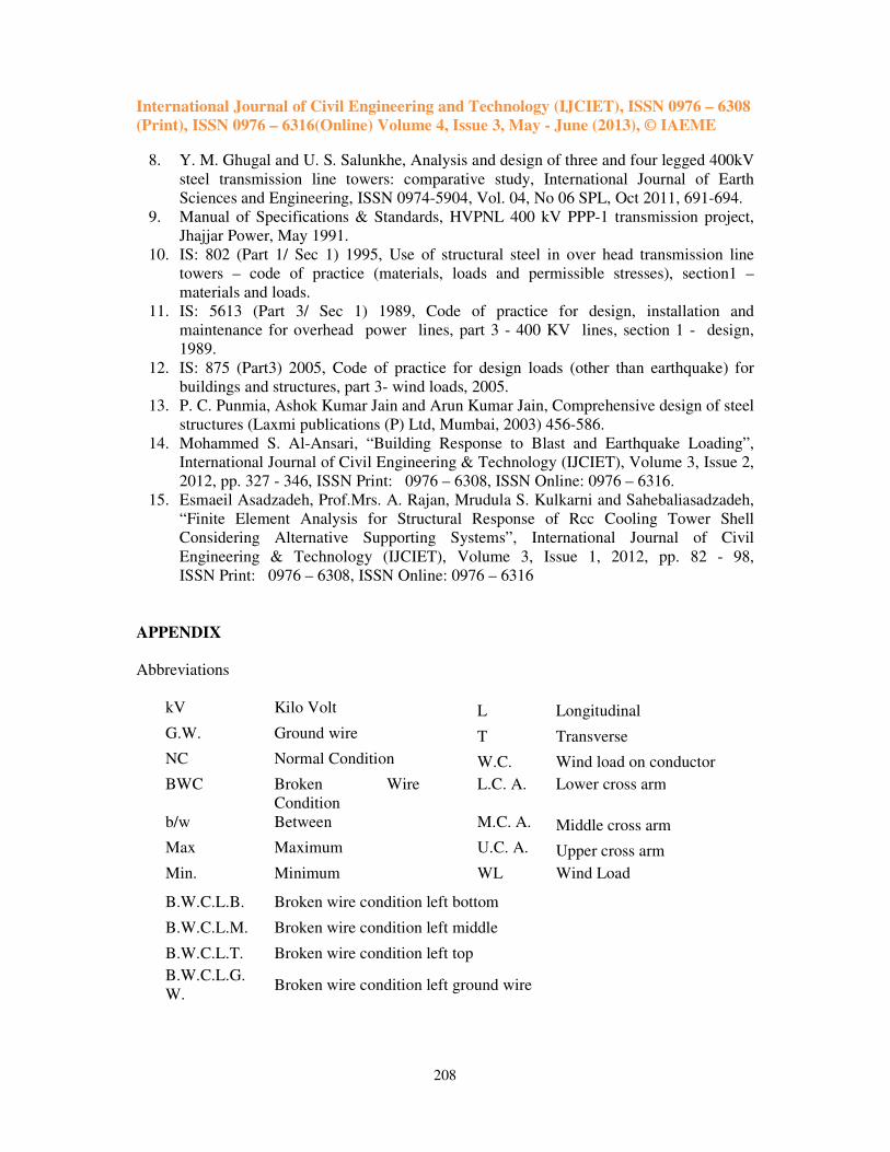
APPENDIX
Abbreviations
kV Kilo Volt L Longitudinal
G.W. Ground wire T Transverse
NC Normal Condition W.C. Wind load on conductor
BWC Broken Wire
Condition
L.C. A. Lower cross arm
b/w Between M.C. A. Middle cross arm
Max Maximum U.C. A. Upper cross arm
Min. Minimum WL Wind Load
B.W.C.L.B. Broken wire condition left bottom
B.W.C.L.M. Broken wire condition left middle
B.W.C.L.T. Broken wire condition left top
B.W.C.L.G.
W. Broken wire condition left ground wire
International Journal of Civil Engineering and Technology (IJCIET), ISSN 0976 – 6308
(Print), ISSN 0976 – 6316(Online) Volume 4, Issue 3, May - June (2013), © IAEME
209
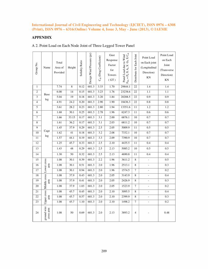
APPENDIX
A 2. Point Load on Each Node Joint of Three Legged Tower Panel
Gro
up N
o.
Name
Total
Area of
Provided
Height
Soli
dit
y R
atio
Des
ign W
ind P
ress
ure
(pz)
Cd
t (D
rag C
oef
fici
ent)
Gust
Response
Factor
for
Towers
( GT )
Panel
Load d
ue
to W
ind
FW
t =
Pd X
Ae
X
GT X
Cd
t
Dis
trib
ute
for
Eac
h J
oin
t
Point Load
on Each joint
(Longitudinal
Direction)
KN
Point Load
on Each
Joint
(Transverse
Direction)
KN
1
Base
leg
7.74 8 0.12 681.3 3.33 1.70 29844.1 22 1.4 1.4
2 6.00 14 0.15 681.3 3.23 1.76 23238.6 22 1.1 1.1
3 5.04 19 0.18 681.3 3.20 1.84 20208.5 22 0.9 0.9
4 4.91 24.2 0.20 681.3 2.90 1.90 18436.3 22 0.8 0.8
5 3.61 28.2 0.23 681.3 2.80 1.94 13351.6 11 1.2 1.2
6
Cage
leg
1.68 30.1 0.25 681.3 2.78 1.96 6247.3 11 0.6 0.6
7 1.66 33.15 0.17 681.3 3.1 2.00 6876.1 10 0.7 0.7
8 1.61 36.2 0.17 681.3 3.1 2.03 6811.2 10 0.7 0.7
9 1.45 37.9 0.29 681.3 2.5 2.05 5009.9 11 0.5 0.5
10 1.62 41 0.18 681.3 3.2 2.08 7332.1 10 0.7 0.7
11 1.57 44.1 0.19 681.3 3.3 2.09 7390.9 10 0.7 0.7
12 1.25 45.7 0.33 681.3 2.5 2.10 4435.5 11 0.4 0.4
13 1.43 48 0.29 681.3 2.5 2.13 5085.2 10 0.5 0.5
14 1.30 50 0.32 681.3 2.5 2.13 4690.8 11 0.4 0.4
15
Low
er c
ross
arm
1.08 30.1 0.39 681.3 2.2 1.96 3611.2 8 - 0.5
16 1.08 30.1 0.51 681.3 2.0 1.96 2513.1 8 - 0.3
17 1.08 30.1 0.94 681.3 2.0 1.96 1574.5 7 - 0.2
18
Mid
dle
cro
ss
arm
1.08 37.9 0.43 681.3 2.0 2.05 3143.9 8 - 0.4
19 1.08 37.9 0.41 681.3 2.0 2.05 2426.9 8 - 0.3
20 1.08 37.9 1.03 681.3 2.0 2.05 1523.9 7 - 0.2
21
Upper
cro
ss
arm
1.08 45.7 0.45 681.3 2.0 2.10 3095.5 8 - 0.4
22 1.08 45.7 0.57 681.3 2.0 2.10 2399.9 8 - 0.3
23 1.08 45.7 1.10 681.3 2.0 2.10 1498.2 7 - 0.2
24
gro
und w
ire
cross
arm
1.08 50 0.69 681.3 2.0 2.13 3893.2 4 - 0.48