integration of machining mechanistic models into cam … · of machining process like 5-axis...
TRANSCRIPT

Journal of Machine Engineering, Vol. 14, No. 4, 2014
simulation, mechanistic, modelling, CAM integration
Jon Ander SARASUA1* Itxaso CASCON1
INTEGRATION OF MACHINING MECHANISTIC MODELS INTO CAM SOFTWARE
Due to the increasing requirements of 5-axis machined products, collision simulation is not enough to ensure final quality. Hence, machining simulation models have been developed and commercialized in the last years. Mechanistic (semiempirical) models give approximate estimations of cutting forces during a whole tool path and, even not being very accurate, they are very useful to detect critical tool path steps, adapt cutting parameters and avoid machine overload. The main problem of most of these models is the fact that they work isolated from CAM programs and so, all the required information must be manually imported and refreshed. This paper presents the integration of an open programmed mechanistic model into commercial CAM software. CAM simulates material removal process, while the model calculates and plots cutting efforts, and power. The whole simulation is performed into CAM environment and any kind of change in the process (tool, material, tool path, cutting speed, etc.) is automatically transferred to the mechanistic model. In the end, the user gets a CNC code that ensures not only collision avoidance, but also adequate process conditions.
1. INTRODUCTION
Simulation of cutting efforts is a very well known field among machining researchers. Mechanistic and FEM based models are widely used, not only to study cutting forces, but also vibration, tool wear, residual stresses and even metal phase changes. FEM based models simulate the behaviour of cutting process during milliseconds (one or two revolutions) and they are able to predict any kind of physical phenomena that finite elements can describe. They give quite accurate results, but their computational cost is expensive.
Mechanistic models are based in the use of experimentally obtained coefficients and, even not being always accurate, they are able to calculate cutting efforts during a whole tool path. The most widely used models are the exponential one proposed by Victor-Kienzle [1] and the linear one including ploughing effect proposed by Armarego [2]. In both cases, cutting forces are proportional to chip instant area and experimentally obtained coefficients. Many authors such as Tuysuz et al [3] have improved these models by _________________ 1 IK4-Tekniker, Advanced Manufacturing Technologies, Eibar, Spain. * E-mail: [email protected]

6 Jon Ander SARASUA, Itxaso CASCON adding the effect of more physical phenomena, such as tool indentation. Other authors such as Zatarain, Munoa and Insperger [4] have used the same principles not to calculate forces, but to predict chatter instability.
Moreover, the calculation of tool-workpiece engagements is also object of study [5],[6] as it directly influences the simulation speed and memory requirements. Most authors obtain engagement domains by analytic, B-Nurbs, dexel, voxel, and STL triangulation representations. The application fields of this kind of models includes most metal cutting processes such as turning, drilling, 5-axis milling, boring or broaching and even complex processes such as thread milling [7].
There are many commercial software packages that give the user not only the chance to predict forces, but also to adapt feed rate, saving time during trials and increasing productivity. Nevertheless, this knowledge is still in hands of universities, researching centres and few companies.
The key of transferring this knowledge to the machining industry lays on the development of easy-to-use CAM integrated applications that ensure fast and reliable results without losing time during models pre-processing step. For example, Chérif et al [8] presented a generic predictive model able to provide the CAD/CAM requirements with minimum experiment testing; analyzing the influence of different parameters (rake angle, cutting speed) on the cutting forces; and Li et al [9] developed a process simulation and optimization system, BetterCut, integrated with NX. Lamikiz et al [10] have researched in the integration of models that calculate a tool path that optimizes cutting forces. Tunc and Budak [11] created a model that uses the information contained in the CL file (Cutter Location file) provided by the CAD/CAM software (tool tip coordinate, tool axis vector and other process parameters required by the computer numerical control) and the STL of the geometry to analytically calculate the milling conditions.
The present paper presents a methodology to integrate mechanistic models into NX CAM commercial software. In the same way as FEM software, the process is divided into three steps:
• Pre-processing: CAM data reading; • Processing: mechanistic calculation; • Post-processing: results plotting.
The paper is organized as follows:
• Modelling steps (pre-processing, processing and post-processing); • Working environment; • Results validation; • Conclusions.
The model and working methodology is prepared to deal with any kind
of machining process like 5-axis milling, turning, drilling, boring, etc. but the paper will be focused on a simple 3-axis milling example. The obtained geometrical information (engagement domains) is useful for other mechanistic models for vibration, chatter instability and tool wear prediction.
Integration of Machining Mechanistic Models into CAM Software 7
2. MODELLING STEPS
2.1. PRE-PROCESSING: CAM DATA READING
The main objective of this step is to prevent the user from wrong data transferring and time waste. All the necessary data is automatically taken from CAM software and transformed into two main files:
• CL file including tool geometry, workpiece material and toolpath; • STL file containing the initial blank geometry.
CL file CL (cutter location) is the output file of an APT processor. This file runs through a post-processor that finally gives the machine CNC code. CL files (CLS extension) are automatically generated by NX and they include:
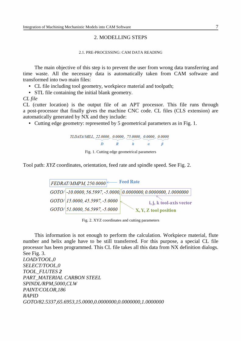
• Cutting edge geometry: represented by 5 geometrical parameters as in Fig. 1.
Fig. 1. Cutting edge geometrical parameters
Tool path: XYZ coordinates, orientation, feed rate and spindle speed. See Fig. 2.
Fig. 2. XYZ coordinates and cutting parameters
This information is not enough to perform the calculation. Workpiece material, flute number and helix angle have to be still transferred. For this purpose, a special CL file processor has been programmed. This CL file takes all this data from NX definition dialogs. See Fig. 3. LOAD/TOOL,0 SELECT/TOOL,0 TOOL_FLUTES 2 PART_MATERIAL CARBON STEEL SPINDL/RPM,5000,CLW PAINT/COLOR,186 RAPID GOTO/82.5337,65.6953,15.0000,0.0000000,0.0000000,1.0000000

8 Jon Ander SARASUA, Itxaso CASCON
Fig. 3. NX blank, workpiece and tool definition dialogs
STL file
This file includes the blank geometry that will be machined, represented by triangular faces. Even not being as accurate as other standard formats such as IGS, Parasolid or STEP, STL format is the most suitable one when representing very complex unparameterized geometries. NX CAM creates automatically this type of representations during the material removal simulation. The blank geometry can be a user’s predefined geometry or the result of previous machining steps.
2.2. PROCESSING: MECHANISTIC CALCULATION
The proposed mechanistic model is based on the expressions presented by Altintas [12] which uses six empirical specific cutting coefficients obtained from experiments: Ktc, Krc, Kac, Kte, Kre and Kae.
The basic equation of the force model includes two actions. On one hand, the force component related to the material shearing action (proportional to undeformed chip section) given by the Kic coefficients. On the other hand, the component related to the friction, rubbing and ploughing actions (proportional to elementary length of the cutting edge: dS), given by the Kie coefficients; where i means tangential, radial or axial.
��� � ����� � ����� (1) ��� � ����� � ����� (2) ��� � ����� � ����� (3)
The cutting edge geometry is obtained from the CL file and it is discretized into N differential Z planes. Each element has an independent dS length and db height. At the same time, for each tool path position, every tooth makes a whole revolution, discretized into T differential angular divisions. T must be always an integer multiple of the teeth number.

Integration of Machining Mechanistic Models into CAM Software 9
Chip thickness (hn) is obtained as follows: h� � f� � sin�θ�t�� � cos�α� � fz � sin�α�/tan(κ#) (4)
where fz is the feed per tooth and θ(t) is the rotated angle including helical variation, $� is the lead angle for each element and α is the feed inclination angle with respect to XY plane [13].
The integration of the equations during the whole tool path is divided into two main steps: engagement domain obtaining and force summation. Engagement domain obtaining
The engagement domain is the geometrical area where the tooth is in contact with the workpiece. This domain is represented as a 4D Boolean matrix as shown in Fig. 4.
Fig. 4. 4D Boolean matrix. 3D point and flat matrix representations
This matrix is obtained as follows:
Firstly, a point cloud representing the revolution of a single tooth is oriented and copied in each tool path position, including a differential increment in feed direction. All the copies are pasted in the same matrix as a global point cloud. This matrix has four columns (X,Y,Z and B), B being the Boolean value (0 initially).
Secondly, using sweep volume analytic equations, all the points not eliminated by previous tool motions turn into 1 in their Boolean value. Swept volumes are represented as follows: �% & %'�(��) � �* & *'�(��) � +�,�) (5)

10 Jon Ander SARASUA, Itxaso CASCON
Each tool path step defines the relation y' � f�x'� for x'�t/� and x'�t)� positions. Solving the equation, all the X,Y,Z points that give real x' values between x'�t/� and x'�t)� are inside this volume as shown in Fig. 5.
In case of having Z displacements, the equation shall be solved by iterating.
Fig. 5. In red, engagement surface points without taking into account initial blank geometry
Finally, the resulting points are analyzed by a catch in-out algorithm [Holcombe 2013] that determines whether they are inside the initial STL blank geometry or not, as shown in Fig. 6. The ones out turn into 1 in their Boolean value.
Fig. 6. In red, engagement surface points taking into account initial blank geometry. In green, initial blank STL geometry
This point cloud is reshaped as a Boolean matrix and the Boolean values as inverted by ‘not’ function.
Force summation
In the same way as the 4D Boolean engagement matrix, three 4D force matrixes are calculated taking into account Altintas’ force equations (1),(2),(3). These matrixes represent for each element the tangential, radial and axial force components, which are transformed into the X (feed), Y (normal) and Z (axial) directions by the following transformations [12]:

Integration of Machining Mechanistic Models into CAM Software 11
0dFXdFYdFZ
1= 2-cos(θ) - sin�θ� sin(κr) - sin�θ� cos(κr)sin(θ) - cos�θ� sin(κr) - cos�θ� cos(κr)0 cos(κr) -sin(κr)
3 0dF6dF#dF71(6)
where θ is the tool rotation angular position and κr is the lead angle for each cutting edge discrete element. The total force is calculated by multiplying force matrix and engagement Boolean matrix, and adding all the contributions for each discrete element of each tooth. 8F69=∑ ∑ 8dF69N
1Z1 (7)
where Z is the number of teeth and N is the number of discretization planes in each tooth. This parameter N could be modified depending on the accuracy required.
As a result, three 3D matrices are obtained for Fx, Fy and Fz respectively, each one containing the magnitude of the cutting forces during a complete revolution of the tool for each position of the tool path in the local coordinate system (relative to the tool). Fx, Fy and Fz are transformed by rotation into the Absolute Coordinate System as shown in Fig. 7, according to the feeding angle.
Fig. 7. XYZ cutting forces in absolute coordinate system
Besides, the total tangential force is calculated in the same way, and thus, the Power
consumption and Torque.
Power=Ft·;c60
(8)
Torque=Ft·R (9)
where Vc is the cutting speed and R is the nominal radius of the tool.

12 Jon Ander SARASUA, Itxaso CASCON
2.3. POST-PROCESSING: RESULT PLOTTING
For each tool position and magnitude, the maximum absolute value is selected and stored in a result matrix. This matrix is saved in a txt file including the next columns:
• Tool path positions’ XYZ coordinates;
• Maximum cutting force, moment (torque) and power consumption magnitudes for each position;
• NX colour identification numbers according to cutting forces’ magnitude. The programmed open NX application creates a group of lines by linking each tool
path XYZ coordinate. Once the lines are created, the user can choose which magnitude shall be plotted (Fx [N], Fy [N], Fz [N], M [Nm], or P [W]). Each magnitude gives colour and name to each line. The given name is the exact value.
For example: FX 750N Similarly to a FEM post-processor, the user can analyze the whole tool path by colours and predict which areas could be conflictive, as shown in Fig. 8.
Fig. 8. Coloured tool path. X cutting force component.350 points and 18 seconds of calculation time
3. WORKING ENVIRONMENT AND VALIDATION EXAMPLE
Due to the integration level of the programs, the only working environment is the one from CAM. Data exporting and model running are programmed in the same command. Results are plotted by commands according to each variable. See Fig. 9.

Integration of Machining Mechanistic Models into CAM Software 13
(a)
(b)
(c)
Fig. 9. NX Working environment commands (a, b) and NX material removal simulation (c)
In combination whit CAM’s tool path verifier, the user can correlate the cutting force results with material removal process. As an example, a simple increasing circular box has been performed with a down milling operation. The results show three expected result plotted in Fig. 10:
• An inverse relation between tool path radius and cutting forces;
• An area near circle connections where forces and power are drastically reduced;
• Power peaks during circle connections. The first phenomenon is directly related to the engagement surface between two
tangent circles. The engagement surface will be reduced until the tool path radius becomes infinite (linear movement).

14 Jon Ander SARASUA, Itxaso CASCON
Fig. 10. Coloured tool path corresponding to cutting power consumption
The second case is related to the union lines between circles. Analyzing the material
removal process, it is observed that during the approach to the union lines, the engagement domain is reduced until the cutting forces become zero. During unions (slotting), radial depth is 100% and power reaches its maximum value.
Fig. 11. Engagement surface change during a single circular movement
A real power measurement has been done in order to validate simulation results.
A circular box corresponding to Fig. 11 has been machined with cutting conditions contained in Table 1.
Table 1. Cutting conditions during validation test
Spindle speed [rev/min] Linear feed [mm/rev/tooth] Axial depth of cut [mm]
2400 0.07 1
2400 0.07 2
The test has been performed in a Deckel Maho DMU 100T 5-axis milling machine (Fig. 12) and the power signal has been measured directly from Heidenhain oscilloscope function. The cutting tool is Mitsubishi VFMHVRBCHD1600R100: Tungsten carbide, 4 flutes, 16mm diameter, 1mm corner radius and variable helix angle to avoid vibration.
Workpiece material is AISI 1045 and the cutting coefficients are the ones in Table 2.

Integration of Machining Mechanistic Models into CAM Software 15
Table 2. Cutting coefficients
Ktc [MPa] Krc [Mpa] Kac [MPa]
1410 163 190
Kte [MPa] Kre [MPa] Kae [MPa]
80 8.5 11.5
Fig. 12. Machining test set up
The simulation has been performed in 17 seconds and time vectors for both signals have been centred.
Fig. 13. Simulated force components in X Y and Z directions
Fig. 14. Simulation peaks (red) and real test (blue) power signals for ap=1mm

16 Jon Ander SARASUA, Itxaso CASCON
Fig. 15. Simulation power results plotted in NX environment
Simulation results (Fig. 15) are in agreement with measured power signal (Fig. 14) There is an initial opening area with high power values and 7 flat areas, corresponding to each circle. Between each circle, power first tends to reduce (approximation to union lines) and then it slotting occurs, duplicating its value. Even not being very accurate results (the first circle gives higher real power values) the global process behaviour is the same one.
4. CONCLUSIONS
The present paper presents the integration of machining force mechanistic models into commercial CAM software. The whole analysis is divided into three steps (pre-processing, processing and post-processing). All input data is automatically refreshed so that the user only has to run the model and plot results. Results’ plotting is based on a rainbow coloured tool path and each GOTO segment’s name corresponds to the plotted magnitude.
The proposed method avoids the user from time wasting and excessive initial set up costs due to:
• Early detection and correction of conflictive tool path steps; • Feed scheduling according to cutting forces; • Selection of optimal relationship between cutting forces and production time; • Selection of optimal cutting strategy.
In combination with CAM’s material removal simulator, the present application gives the chance to understand cutting efforts variation during the whole tool path. Simulations’ results have been validated with real simple machining tests, obtaining good results during the whole tool path. More complex examples might be performed to analyse dependencies between cutting coefficients and cutting forces.
ACKNOWLEDGEMENTS
The authors thank the Ministry for Economic Development and Competitiveness and the Department of Industry, Innovation, Trade and Tourism of the Basque Government, as well as the European Regional Development Fund for the financial support of this work, which is part of the AMICAM project, developed under the GAITEK program and INPRORET project, developed under the ETORTEK program.

Integration of Machining Mechanistic Models into CAM Software 17
REFERENCES
[1] KIENZLE O., VICTOR H., 1957, Spezifische Schnittkrafte bei der Metallbearbeitung, Werkstoffteechnik und Machinenbau, 47/5, 224–225.
[2] ARMAREGO E.J.A., BROWN R.H., 1969, The Machining of Metals, Prentice-Hall. [3] TUYSUZ O., ALTINTAS Y., FENG H.Y., 2013, Prediction of cutting forces in three and five-axis ball-end
milling with tool indentation effect, International Journal of Machine Tools & Manufacture, 66, 66–81.
[4] ZATARAIN M., MUNOA J., PEIGNÉ G., INSPERGER T., 2006, Analysis of the influence of mill helix angle on chatter stability, CIRP Annals-Manufacturing Technology, 55/1, 365–368.
[5] SULLIVAN A., ERDIM H., PERRY R.N., FRISKEN S.F., 2012, High accuracy NC milling simulation using composite adaptively sampled distance fields, Comput. Aided Des, 522–536.
[6] KAYMAKCI M., LAZOGLU I., 2008, Tool path selection strategies for complex sculptured surface machining, Mach. Sci. Tecnhol., 12, 119–132.
[7] LEE S.W., KASTEN A., NESTLER A., 2013, Analytic mechanistic cutting force model for thread milling operations, 14th CIRP Conference on Modelling of Machining Operations, CIRP CMMO, 8, 546–551.
[8] CHÉRIF M., THOMAS H., FURET B., HASCOËT J.Y., 2004, Generic modelling of milling forces for CAD/CAM applications, Int. J. Mach. Tools Manuf., 44, 29–37.
[9] LI Z.Z., ZHENG M., ZHENG L., WU Z.J., LIU D.C., 2003, A solid model-based milling process simulation and optimization system integrated with CAD/CAM, J. Mater. Process. Technol., 138, 513–517.
[10] LAMIKIZ A., LÓPEZ D.E., LACALLE L.N., SÁNCHEZ J.A., SALGADO M.A., 2005, Cutting force integration at the CAM stage in the high-speed milling of complex surfaces, Int. J. Comput. Integr. Manuf., 18, 586-600.
[11] TUNC L.T., BUDAK E., 2009, Extraction of 5-axis milling conditions from CAM data for process simulation, Int. J. Adv. Manuf. Technol., 43, 538–550.
[12] ALTINTAS Y ., 2000, Manufacturing automation: metal cutting mechanics machine tool vibrations and CNC design, Cambridge University Press, United Kingdom.
[13] ERDIM H., LAZOGLU I., KAYMAKCI M., 2007, Free- form surface machining and comparing feedrate scheduling strategies machining science and technology, 11/1, 117–133.
[14] HOLCOMBE S., 2014, Inpolyhedron - are points inside a triangulated volume?, http://www.mathworks.es /matlabcentral/fileexchange/37856-inpolyhedron-are-points-inside-a-triangulated-volume