integration of external libraries into the foundational ... · integration of external libraries...
TRANSCRIPT

Integration of External Librariesinto the Foundational Subset of
UMLDIPLOMARBEIT
zur Erlangung des akademischen Grades
Diplom-Ingenieur
im Rahmen des Studiums
Wirtschaftsinformatik
eingereicht von
Patrick NeubauerMatrikelnummer 1028573
an derFakultät für Informatik der Technischen Universität Wien
Betreuung: O.Univ.Prof. Dipl.-Ing. Mag. Dr.techn. Gerti KappelMitwirkung: Dipl.-Ing. Tanja Mayerhofer, BSc
Wien, 10.02.2014(Unterschrift Verfasser) (Unterschrift Betreuung)
Technische Universität WienA-1040 Wien � Karlsplatz 13 � Tel. +43-1-58801-0 � www.tuwien.ac.at


Integration of External Librariesinto the Foundational Subset of
UMLMASTER’S THESIS
submitted in partial fulfillment of the requirements for the degree of
Diplom-Ingenieur
in
Business Informatics
by
Patrick NeubauerRegistration Number 1028573
to the Faculty of Informaticsat the Vienna University of Technology
Advisor: O.Univ.Prof. Dipl.-Ing. Mag. Dr.techn. Gerti KappelAssistance: Dipl.-Ing. Tanja Mayerhofer, BSc
Vienna, 10.02.2014(Signature of Author) (Signature of Advisor)
Technische Universität WienA-1040 Wien � Karlsplatz 13 � Tel. +43-1-58801-0 � www.tuwien.ac.at


Erklärung zur Verfassung der Arbeit
Patrick NeubauerRembrandtstr. 27/13, 1020 Wien
Hiermit erkläre ich, dass ich diese Arbeit selbständig verfasst habe, dass ich die verwende-ten Quellen und Hilfsmittel vollständig angegeben habe und dass ich die Stellen der Arbeit -einschließlich Tabellen, Karten und Abbildungen -, die anderen Werken oder dem Internet imWortlaut oder dem Sinn nach entnommen sind, auf jeden Fall unter Angabe der Quelle als Ent-lehnung kenntlich gemacht habe.
Wien, 10. Februar 2014
(Unterschrift Verfasser)
i


“Imagination is everything. It is the preview of life’s coming attractions.”
Albert Einstein


Acknowledgements
Many people brought in effort to this thesis, my education and the prototype realized as part ofthis work. I greatly reward the opportunity to have come across so many wonderful people, andit is now my great pleasure to take this opportunity to thank them.
First and foremost, I would like to express my sincere gratitude to my thesis assistance TanjaMayerhofer for her continuous support that finally led to the completion of this work. Hermotivation, enthusiasm, patience, and immense knowledge guided me all the time while bothcreating the prototype and writing this thesis. Sincere thanks also to my thesis advisor Prof.Kappel who took very good care in arranging all events.
I also thank Philip Langer and Manuel Wimmer for their support and motivation at the verybeginning that led to the final decision of choosing this particular topic. Thanks also to UweBrunflicker who carefully answered my questions.
Special thanks goes to my girlfriend, Mirjam Raffeiner, and my family and friends for all theirlove and spiritual support along the way.
v


Abstract
With the introduction of OMG’s Foundational UML (fUML) standard, that precisely definesthe execution semantics for a subset of UML, and the conforming virtual machine, completelyexecutable systems can be built and executed with UML. However, the full potential of havingexecutable models has yet to be unleashed. An important aspect that increases the potential ofexecutable models is the ability to re-use existing software components since that reportedly in-creases the overall quality and productivity of the software development process. Furthermore,large-scale software that is produced nowadays, involves the usage of a high number of existingsoftware components primarily in form of software libraries (i.e., APIs provided for the usedprogramming language).
This thesis identified that the fUML standard does not offer a procedure to use softwarelibraries. In fact, creating models that build on top of software libraries is not foreseen in thefUML standard. On the contrary, the standard foresees its extendability through the Founda-tional Model Library. Yet, doing so requires implementing model libraries that basically mimicthe functionality provided by currently existing software libraries. This approach imposes a sig-nificant drawback. It requires a huge amount of dedicated joint effort to build a set of librarieshaving similar functional coverage and sophistication as the existing set of software libraries.
The research question of this thesis is as follows. Is the fUML virtual machine extendable,such that it allows the execution of models referencing external software libraries? Within thiswork, an approach has been elaborated that enables to use external software libraries in fUMLmodels. The applicability of this approach has been shown by implementing a prototypical Inte-gration Layer that is able to integrate Java libraries with the fUML virtual machine such that themodeler can benefit from the advanced and complex functionalities provided by those libraries.This prototype focuses on creating instances of library classes and calling library operations.Moreover, a two-step procedure to make existing libraries available for their usage in fUMLmodels, has been implemented.
While conducting several case studies, experiences have been gained that led to further en-hancements of the prototype and to the following conclusion. The fUML virtual machine can beextended, such that it allows the execution of models referencing external libraries. Neverthe-less, to broaden the applicability of the implemented prototype, and therefore increase the scopeof applicable modeling scenarios, an in-depth investigation on common library use cases andtheir following implementation is recommended.
vii


Kurzfassung
Mit der Einführung von OMG’s Foundational UML (fUML) Standard, der die Ausführungs-semantik für ein Teilmenge von UML und die konforme virtuelle Maschine präzise definiert,können vollständig ausführbare Systeme in UML entwickelt und ausgeführt werden. Das voll-ständige Potenzial von ausführbaren Modellen ist jedoch noch nicht gegeben. Die Möglichkeitder Wiederverwendung von existierenden Softwarekomponenten, die Studien zufolge die Quali-tät und Produktivität des Softwareentwicklungsprozesses gesamtheitlich erhört, ist ein wichtigerAspekt, der das Potenzial von ausführbaren Modellen steigert. Darüber hinaus involviert heuti-ge Software die hochgradige Nutzung von existierenden Softwarekomponenten, primär in Formvon Software Bibliotheken (d.h. zur Verfügung gestellte APIs in der angewandten Programmier-sprache).
Diese Arbeit identifiziert, dass der fUML Standard keine Prozedur um Software Bibliothe-ken zu nutzen zur Verfügung stellt. Tatsache ist, dass das Erstellen von Modellen, die Bibliothe-ken verwenden, im fUML Standard nicht vorgesehen ist. Der Standard sieht dessen Erweiterbar-keit hingegen durch die Foundational Model Library vor. Dies jedoch benötigt die Implemen-tierung von Modellbibliotheken, die im Grunde die Funktionalität von derzeitig existierenden,und damit bereits zur Verfügung gestellten, Bibliotheken imitieren. Dieser Ansatz weist einenerheblichen Nachteil auf. Es wird eine große Menge an gemeinsamen Bemühungen benötigt umeine Menge von Modellbibliotheken aufzubauen, die einen ähnlichen Funktionsumfang bieten,wie die existierende Menge von Software Bibliotheken.
Die Forschungsfrage dieser Arbeit lautet daher: Ist die virtuelle Maschine für fUML Mo-delle erweiterbar, sodass diese die Ausführung von Modellen, die externe Bibliotheken verwen-den, erlaubt? Innerhalb dieser Arbeit wurde ein Ansatz ausgearbeitet, der es ermöglicht Softwa-re Bibliotheken in fUML Modellen zu verwenden. Die Anwendbarkeit dieses Ansatzes wurdenachgewiesen durch die Entwicklung eines prototypischen Integration Layers der fähig ist, Ja-va Bibliotheken mit der fUML virtuellen Maschine zu integrieren, sodass der Modellierer vonderen Funktionalität profitieren kann. Dieser Prototyp fokusiert sich auf die Instantiierung vonBibliotheksklassen und den Aufruf von Bibliotheksoperationen.
Während der Durchführung verschiedener Fallbeispielen wurden Erfahrungen gewonnen,die zur Weiterentwicklung des Prototypen, sowie zu folgendem Endergebnis geführt haben: DiefUML virtuelle Maschine kann erweitert werden, sodass diese die Ausführung von Modellen,die externe Bibliotheken verwenden, erlaubt. Um jedoch die Anwendbarkeit des implementier-ten Prototypen, und damit den Umfang der anwendbaren Modellierungsszenarien zu erweitern,wird eine eingehende Untersuchung von verbreiteten Anwendungsfällen für die Verwendungvon Bilbiotheken, sowie deren Implementierung, empfohlen.
ix


Contents
1 Introduction 11.1 Motivation . . . . . . . . . . . . . . . . . . . . . . . . . . . . . . . . . . . . . 11.2 Problem Statement . . . . . . . . . . . . . . . . . . . . . . . . . . . . . . . . 31.3 Aim of the Work . . . . . . . . . . . . . . . . . . . . . . . . . . . . . . . . . 31.4 Methodological Approach . . . . . . . . . . . . . . . . . . . . . . . . . . . . 41.5 Structure of the Work . . . . . . . . . . . . . . . . . . . . . . . . . . . . . . . 5
2 UML 72.1 Introduction to UML . . . . . . . . . . . . . . . . . . . . . . . . . . . . . . . 72.2 UML Metamodel . . . . . . . . . . . . . . . . . . . . . . . . . . . . . . . . . 82.3 UML Diagram Types . . . . . . . . . . . . . . . . . . . . . . . . . . . . . . . 82.4 Class Diagrams to Capture Structure . . . . . . . . . . . . . . . . . . . . . . . 102.5 Activity Diagrams to Capture Behavior . . . . . . . . . . . . . . . . . . . . . 13
3 Executable UML 193.1 Introduction to Foundational UML . . . . . . . . . . . . . . . . . . . . . . . . 193.2 Syntax of Foundational UML . . . . . . . . . . . . . . . . . . . . . . . . . . . 203.3 Semantics of Foundational UML . . . . . . . . . . . . . . . . . . . . . . . . . 243.4 Foundational Model Library . . . . . . . . . . . . . . . . . . . . . . . . . . . 28
4 Overview on the Foundational UML Library Support 314.1 Introduction to the Integration Layer Concept . . . . . . . . . . . . . . . . . . 314.2 Reverse Engineering of External Libraries . . . . . . . . . . . . . . . . . . . . 334.3 Preparation of Library UML Models . . . . . . . . . . . . . . . . . . . . . . . 354.4 Definition of UML Models Referencing External Libraries . . . . . . . . . . . 374.5 Execution of UML Models Referencing External Libraries . . . . . . . . . . . 38
5 Reverse Engineering of Java Libraries 435.1 Introduction to Reverse Engineering . . . . . . . . . . . . . . . . . . . . . . . 435.2 Reverse Engineering Using MoDisco Model Discovery Tool . . . . . . . . . . 445.3 ATLAS Transformation Language . . . . . . . . . . . . . . . . . . . . . . . . 495.4 Reverse Engineering Libraries: An Example . . . . . . . . . . . . . . . . . . . 51
6 Modeling with fUML Using External Libraries 57
xi

6.1 Preparing Reverse Engineered UML Model . . . . . . . . . . . . . . . . . . . 576.2 Implementation of Preparing a UML Model . . . . . . . . . . . . . . . . . . . 626.3 Building a UML Model Referencing an External Library . . . . . . . . . . . . 65
7 Executing Foundational UML Models Integrating External Libraries 777.1 Java Reflection and Dynamic Class Loading . . . . . . . . . . . . . . . . . . . 777.2 Executing fUML Models Referencing External Libraries . . . . . . . . . . . . 817.3 Foundational UML External Library Eclipse Plugin . . . . . . . . . . . . . . . 867.4 Prototype Capabilities . . . . . . . . . . . . . . . . . . . . . . . . . . . . . . . 887.5 Prototype Limitations . . . . . . . . . . . . . . . . . . . . . . . . . . . . . . . 94
8 Case Studies and Lessons Learned 998.1 Research Questions . . . . . . . . . . . . . . . . . . . . . . . . . . . . . . . . 998.2 Experimental Setup . . . . . . . . . . . . . . . . . . . . . . . . . . . . . . . . 1008.3 Mail Case Study . . . . . . . . . . . . . . . . . . . . . . . . . . . . . . . . . . 1008.4 Petstore Case Study . . . . . . . . . . . . . . . . . . . . . . . . . . . . . . . . 1068.5 Database Case Study . . . . . . . . . . . . . . . . . . . . . . . . . . . . . . . 1118.6 Lessons Learned . . . . . . . . . . . . . . . . . . . . . . . . . . . . . . . . . 1178.7 Threats to Validity . . . . . . . . . . . . . . . . . . . . . . . . . . . . . . . . . 118
9 Related Work 1199.1 Approaches Taken by Other fUML Compliant Tools . . . . . . . . . . . . . . . 1199.2 The fUML Foundational Model Library and Similar Approaches . . . . . . . . 1239.3 Other Approaches . . . . . . . . . . . . . . . . . . . . . . . . . . . . . . . . . 123
10 Conclusion 12710.1 Summary . . . . . . . . . . . . . . . . . . . . . . . . . . . . . . . . . . . . . 12710.2 Future Work . . . . . . . . . . . . . . . . . . . . . . . . . . . . . . . . . . . . 129
Bibliography 131
xii
CHAPTER 1Introduction
This chapter introduces the reader to the context of this master’s thesis and states the motivation,problem, aim, methodological approach and structure of this work.
1.1 Motivation
In Model Driven Engineering (MDE), the focus of software development is shifted from codingto modeling [18] to automate the software development process by using modeling languagesand model transformation, as well as code generation [19]. Therefore, MDE promotes the sys-tematic use of software abstractions in terms of models as primary artifacts during a softwareengineering process. MDE claims to have many benefits, such as increasing productivity, porta-bility, interoperability, and maintainablity, but also organizational benefits such as the ability ofabstraction that allows to see the bigger picture [14]. The usage of MDE has reportedly lead toproductivity increases ranging from 20 to 800 percent [14].
Users of MDE employ different modeling languages. The Unified Modeling Language(UML) [30], standardized by the Object Management Group (OMG), is used by about 85 percentof MDE users [14].
Formal specification techniques are particularly relevant to MDE since modeling languagesmust have a formally defined semantics if they are used to create analyzable models. There-fore, it is suggested, that appropriate aspects of modeling languages must be formalized [9].Currently, popular modeling languages, such as UML, have the shortcoming of informally andimprecisely defined semantics that makes semantic-based manipulations of models difficult.
The OMG recently defined the Foundational Subset of UML (fUML) standard [31] that isintended to give UML formal execution semantics. It precisely defines the execution semanticsfor a defined subset of UML by dealing with the structural foundation layer and the behavioralbase layer (includes Actions, Inter-Object Behavior Base, and Intra-Object Behavior Base) andActivities of UML as depicted in Figure 1.1. Specifically, fUML provides a standardized virtualmachine capable of executing activities compliant to the UML subset contained in fUML.
1

Figure 1.1: Semantic areas of UML [30].
With the standardization of executable UML, referred to as fUML, execution semantics havebeen added to a subset of UML. The fUML specification together with an fUML virtual machineallows to interpret (i.e., execute) fUML models. However, when modeling executable modelsbased on the fUML standard, none of the libraries that already exist in general purpose program-ming languages, such as the Java programming language, can be used. That fact imposes majordrawbacks when it comes to building sophisticated applications in a timely and qualitativelyreasonable manner. As pointed out by Mayerhofer et al. [22], these drawbacks occur becausethe modeler is unable to take advantage of powerful libraries when constructing models and thusapplications. The reason for the latter drawback is that such libraries, that exist in a generalpurpose programming language like Java, simply do not (yet) exist in the action language offUML.
These days, when building an fUML activity model performing a simple task, such as com-posing and sending an e-mail message to some recipient, for which a general purpose program-ming provides simple-and-quick-to-use libraries, the whole (used) logic behind such librariesneeds to be re-implemented with fUML. Re-using software components, for example in formof external libraries, allows to incorporate already well established and tested application logicinto newly written applications. In other words, to use a metaphor: wheels do not need to bereinvented. When adding a dedicated layer to the fUML virtual machine that is able to interpret,for example, operation calls to an external library, the modeler can take advantage of alreadywell-established software components.
Thus, since the overall quality and productivity to build applications is improved by re-using software components [15], it might as well improve the quality and productivity to buildapplications in form of executable fUML models.
2

1.2 Problem Statement
Libraries in modern general-purpose programming languages (GPL) provide access to huge,already implemented, applications. For example, the Java Class Library (JCL)1 provides corelibraries, integration libraries, user interface libraries, and many more. The integration libraryincludes, e.g., the Java Database Connectivity (JDBC) API that allows the developer to rapidlyaccess a database. In Java there is also a huge amount of third party libraries available. Oneprominent example is Apache Commons2. Those libraries and APIs are powerful since theyallow using well established and tested code that improves software productivity by speeding upthe software development process. Additionally, software quality is increased by the usage ofwell tested library code.
While the fUML virtual machine is developed in Java and does allow the execution of fUMLmodels, it does not provide the ability to integrate and invoke external Java libraries from models.In other words, the fUML virtual machine does not make external libraries available to be usedby the modeler, which imposes a significant drawback. Since libraries are nowadays widelyused in the software development process, the rapid development of software based on fUML ishindered by its inability of providing the benefits of external libraries.
In general, the problem is that, when using the fUML virtual machine to execute an fUMLmodel, one cannot invoke a method from an external library and retrieve its result, e.g,. toanalyze the model execution at runtime. Therefore, a modeler could, for instance, not invoke thenextInt() method in java.util.Random to generate a random number for further usagein the model.
1.3 Aim of the Work
In order to cope with the previously stated problem, an approach for integrating external Javalibraries with the fUML virtual machine was proposed by [22]. This includes the integrationof required interfaces and classes of external libraries, into the fUML model. Additionally,a dedicated Integration Layer is proposed to be employed in order to forward calls to libraryclasses to the actual class instance at runtime. By integrating external libraries with the fUMLvirtual machine and employing a dedicted Integration Layer, modelers can benefit from the fullpower provided by external Java libraries. The aim of this thesis is to implement a prototypicalsolution for integrating external libraries with the fUML virtual machine and to evaluate thepracticability of this approach.
Hence, the prototype to be implemented needs to provide the possibility to use externallibraries from within an fUML activity diagram. In order to develop such a prototype, the fol-lowing components and steps are designed and implemented as proposed in [22]:
1The Oracle Java Platform Standard Edition 7 Documentation can be found online at http://docs.oracle.com/javase/7/docs/. Accessed January, 2014.
2Apache Commons library is available online at http://commons.apache.org. Accessed December,2013.
3

Importing external libraries: To make external Java libraries available to the modeler offUML models, a class diagram representation of these external libraries is obtained using a re-verse engineering tool. For importing the interfaces and classes of external libraries, MoDisco [4]or Jar2UML3 can be used. The result of this procedure consist of interfaces, classes, fields, andoperation signatures of the required components. To avoid an information overflow of fUMLmodels, the modeler may manually select certain classes (as, e.g., org.apache.commons.mail.Email) and their class members (as, e.g., EMAIL_SUBJECT) she/he aims to use. Incase, only parts of the external library (like, e.g., the Email class in the org.apache.commons.mail library) are integrated into the fUML model, field types, operation param-eter types and return types4 still have to be imported. In contrast, the bodies of the operationsare omitted from the integrated classes. They are replaced by special place holders (empty fUMLactivities) from which the actual functionality of the external library is triggered at runtime asdescribed in the following.
Integrating external libraries at runtime: In order to integrate external libraries into the exe-cution of an fUML model, a dedicated Integration Layer is developed that is capable of invokingmethods of the previously reverse-engineered library out of the fUML model and integrates theresult (or: return value) obtained from the invoked method call into the fUML runtime model.During the execution of the fUML model, when an activity representing an operation of an ex-ternal library is called, the Integration Layer forwards the call to the external library. In orderto allow this, the Integration Layer is notified on such a call to allow pausing the execution ofthe fUML model until the external library responds with the result. Afterwards, the result of thecall to the external library is incorporated into the runtime model of the executed fUML model.Here, the event mechanism and command API that have been developed and integrated into thestandardized fUML virtual machine [21] is used. Using these extensions allows the creation andmodification of library class objects and the invocation of library functions at runtime. Hence,objects might be created and manipulated.
1.4 Methodological Approach
The research method used within this work is based on the idea of the constructive approachof Design Science [12]. Design Science consists of the two basic activities Build and Evaluate.In the Build activity, models, methods and implementations are built. The Evaluate activityevaluates the performance of the built artifacts related to the environment.
Based on this constructive approach, the following steps are carried out for the mater’s thesis:
3The Eclipse Jar2UML tool has been developed by the Software Languages research lab within the departmentof Computer Science of the Vrije Universiteit Brussel. The official project webpage can be retrieved from http://soft.vub.ac.be/soft/research/mdd/jar2uml. Accessed December, 2013.
4A summary on field types, operation parameter types, and return types of the mentioned example libraryclass Email in org.apache.commons.mail can be found online at http://commons.apache.org/proper/commons-email/apidocs/org/apache/commons/mail/Email.html. Accessed Decem-ber, 2013.
4

Analysis: In this step, existing work concerning fUML and reverse engineering is elaboratedto get a more thorough understanding of the problem at hand, existing solutions, and barriers thathave to be overcome. This guides in getting an understanding about:
• The fUML standard and its utilization.
• The functionality of the fUML virtual machine.
• The fUML extensions: command and event mechanism.
• Reverse engineering tools capable of producing a UML class diagram representation ofJava libraries.
Design: In the design step, an artifact is designed that is implemented by a prototype, whichapproaches the problem of integrating external Java libraries investigated in the Analysis step.The prototype is capable of:
• The integration of a reverse engineered Java API into fUML models.
• Providing a dedicated Integration Layer that forwards calls from the fUML model to thereverse engineered Java API to the actual external library.
• Support of object manipulation actions to allow manipulation of library objects.
During the development phase, reviews are conducted by several researchers for refining andimproving the artifact towards the initially defined goals and/or goals discovered in later stages.
Evaluation: Finally, the practicability of the implemented prototype is evaluated by con-ducting a case study particularly looking at the usability, correctness, and performance whenexecuting fUML models that use external libraries with the designed prototype. Thus, sugges-tions for improvements and future work on the implemented artifact are obtained.
1.5 Structure of the Work
This work is structured into the following additional nine chapters.
Chapter 2 and Chapter 3 present the main theoretical part covering the concepts used in theupcoming chapters. These concepts include UML class and activity diagrams as well as con-cepts used in OMG’s fUML action language.
Chapter 4 is meant to provide an overview to the proposed concept of integrating externallibraries into fUML models.
The subsequent chapters describe the implemented prototype. On one hand, Chapter 5 dis-cusses the reverse engineering process that produces a UML class model.
5

On the other hand, Chapter 6 depicts how to construct fUML activity models that referenceclasses and operations of external libraries.
Chapter 7 discusses how the artifacts created in the previous chapters are used as input forthe Integration Layer that ultimately executes the fUML model referencing external libraries.
Within Chapter 8 case studies performed on the implemented prototype are discussed along-side with the examined research questions and the lessons learned from the studies.
Chapter 9 mentions related work on the state of the art concerning the execution of modelsaccessing external libraries.
The conclusion and the summary of the work are given in Chapter 10. Furthermore, potentialfuture work is also discussed.
6

CHAPTER 2UML
In this section we aim to introduce the reader to the Unified Modeling Language (UML) and itstypes of diagrams used in this work.
2.1 Introduction to UML
Just as Java is a general-purpose programming language, the Unified Modeling Language (UML)is a general-purpose modeling language (GPLs or GPMLs1) commonly used in software engi-neering. UML arose out of the existence of several modeling language definitions and has beenstandardized by the Object Management Group (OMG) in late 1997. Until recently, the OMGreleased several version of UML with version 2.4.1 being the most recent release published inAugust 2011 [30]. In 2000, the International Organization for Standardization (ISO) acceptedUML as an industry standard for modeling software-intensive systems.
Domain Specific Languages vs. General-Purpose Languages
Domain-specific languages (DSLs or DSMLs2) are languages designed for a specific purpose.Thus, they are designed for a specific domain to help people describe phenomena in their specificdomain. UML is a many-domains language (MDL), therefore it may not be a domain-specificlanguage. While a DSL can certainly not model any domain, UML can [3]. On the other hand,UML may not be well suited for all domains but it can be directly applied to easily modelany domain. In case a development project includes some modeling needs that are not com-pletely covered by the UML standard, then one can take advantages of the extensibility featuresprovided by UML. Specifically, stereotypes, constraints, tagged values, and profiles are UMLextension mechanisms which can be used for this purpose.
1GPML stands for general-purpose modeling language2DSML stands for domain-specific modeling language
7

2.2 UML Metamodel
The concepts provided by a modeling language are usually defined by a metamodel that, hence,defines the abstract syntax of a modeling language. While a model is an abstraction of phenom-ena in the real world, a metamodel is an abstraction of a model (i.e., a metamodel describes amodel). In other words, a metamodel defines a modeling language by describing the whole classof models that one can model by using that particular modeling language. Subsequently, meta-metamodels describe metamodels in the same way as metamodels describe models and modelsdescribe real world phenomena. Hence, one can recursively define infinite levels of metamodels.As a result of that, a model (at any level of abstraction) conforms to its metamodel. Analogously,a computer program, written in the Java programming language, conforms to the grammar ofthe Java programming language. Also the abstract syntax of UML is defined by a metamodel.This metamodel consists for instance of the metaclasses “Class” and “Association” which canbe used to define classes, such as the classes “Person” and “Car” and association between theseclasses (cf. Figure 2.1).
Figure 2.1: An example for metamodeling3 [29].
2.3 UML Diagram Types
In general, the OMG UML Superstructure specification version 2.4.1 [30] categorizes UML di-agrams into the two basic types of structure diagrams and behavior diagrams. Subsequently,behavior diagrams can be further classified into interaction diagrams. The most important dis-tinction of these two diagram categories is that, while structure diagrams represent the staticstructure of the objects in a system, behavior diagrams present the dynamic behavior of the ob-jects in a system.
3Note that not all instance-of relationships are shown
8

While structure diagrams do not define dynamic behavior and behavior diagrams do not ex-hibit static structure, they can be related to each other. OMG’s diagram type taxonomy onlyprovides a logical organization of UML modeling concepts and does not inhibit the combinationof various kinds of modeling concepts on the same diagram. In the following, each diagramtype, owned by the diagram categories as depicted in Figure 2.2, is shortly described. Finally,class diagrams and activity diagrams are described in more detail as they play a key role in thiswork.
Figure 2.2: UML version 2.4.1 diagram taxonomy [30].
Structure Diagrams
• The profile diagram operates at metamodel level to show stereotypes as classes, and pro-files as packages. The extension relation denotes the metamodel element that a specificstereotype extends.
• The class diagram describes the system structure by primarily visualizing its classes, theirattributes, and relationships between classes. A more detailed description is available inSection 2.4.
• A composite structure diagram describes the internal structure of a class and its collabo-rations hierarchically. Hence, it can be used to decompose the modeled system.
• A component diagram shows the separation of a system into modular components andhighlights their dependencies between each other.
9

• The deployment diagram describes system artifacts (e.g., a JAR file), execution environ-ments (e.g., Apache Tomcat servlet container) and devices (e.g., the hardware of a server).Therefore, it can illustrate how artifacts are deployed in specific execution environmentson the hardware.
• The object diagram models an either partially or complete instance of the system. In otherwords, objects and their attribute values are modeled together with relationships amongthe objects themselves.
• A package diagram shows how the system is composed (or split) into specific groups (i.e.,packages) and how these groups are related to each other.
Furthermore, in order to describe the behavior of a system, another set of diagrams, as listedbelow are defined by UML.
Behavior Diagrams
• The activity diagram shows the flow of control in a system. Accordingly, it describes theoperational and business workflows (i.e., data and control flows) of each system compo-nent. A more detailed description, including modeling concepts used in these diagrams,is available in Section 2.5.
• A use case diagram typically describes “use case scenarios” from the viewpoint of in-volved actors of the particular system. It shows, in particular, the actor’s goals, relation-ships and dependencies among each other.
• State machine diagrams are based on the mathematical concept of finite automata. Hence,they can be used to describe object life cycles that show actions (or transitions) requiredfor an object to move from one to another state.
• Interaction diagrams are composed of sequence diagrams, communication diagrams, in-teraction overview diagrams, and timing diagrams. They are used to define different as-pects of the interactions between objects of the modeled system.
2.4 Class Diagrams to Capture Structure
UML class diagrams are static structure diagrams that describe the structure of a system byvisualizing system classes, operations, attributes, and relationships among classes [30]. Anexample of a UML class diagram is shown in Figure 2.3. Every box in the class diagram,except the box labeled Person, represents a class. The upper part of the box, also called thename compartment, contains the name of the class and identifies applied stereotypes such as,for example, «interface». The lower part, also called the attributes compartment, containsa list of attributes of a class. The part on the bottom of the box, also called the operationscompartment, displays the operations the class can perform. While the name compartment isrequired in every class definition, the attributes compartment and the operations compartment
10

are optional. For example, the class Order has the attributes date and status and operationscalcTax(), calcTotal(), and calcTotalWeight().
Check
+ na me :String+ ba nkID :int
+ au thorized() :boo lean
Cash
+ cashTen dere d :do uble
Creditcard
+ nu mber :int+ typ e :S tring+ exp Date :Da te
+ au thorized() :boo lean
Customer
+ na me+ address
Item
+ shi pping Weig ht :d oubl e+ de script ion :String
+ ge tPrice ForQuant ity(int ) :do uble+ ge tWeig ht() :doub le
Order
+ da te :Date+ sta tus :S tring
+ cal cTax() :do uble+ cal cTota l() :d oub le+ cal cTota lWei ght() :dou ble
OrderDe tail
+ qu antiti y :int+ taxStatu s :St ring
+ cal cSub Tota l() :d ouble+ cal cWei ght() :dou ble
Payment
+ am ount :dou ble
«in terfa ce»Person
0..*1 1..*1
1
0..*1
1..*
Figure 2.3: UML class diagram example4.
4The UML class diagram example depicted in Figure 2.3 represents a modified version of the UML class diagramfound online at http://edn.embarcadero.com/article/31863. Accessed January, 2014.
11

The most important UML modeling concepts for defining classes are described in the fol-lowing.
Attributes and operations are class members. Two types of members can be defined: clas-sifier members and instance members. The scope of classifier members is limited to the classitself such that method invocations do not affect the instance’s state and attribute values are equalfor all instances. This is similar to the static keyword in Java. On the other hand, instancemembers have a scope bound to their instance, i.e., method invocations can affect the instance’sstate and attribute values can vary between instances.
Relationships, in class diagrams, are logical connections that can take various forms. Ingeneral, relationships can be classified into instance level relationships, class level relationshipsand general relationships. Association, aggregation, and composition are instance level rela-tionships. Realization and generalization are class level relationships. Dependency is a generalrelationship. To clarify, a uni-directional relationship is defined as a relationship capable offlowing in one direction (i.e., from source to target) only and not in both directions like a bi-directional relationship.
An association is represented by a line between classes as depicted in Figure 2.3 by, forexample, the two-ended line connecting the class Customer and the class Order. While thelatter example does not specify a direction in the relationship, an uni-directional relationship isshown from the Order class to the Payment class.
Aggregation is another form of a relationship in UML class diagrams. It represents a typeof “has a” relationship. In Figure 2.3 it is illustrated by the relationship connecting Orderand OrderDetail. It represents the fact that OrderDetail is part of Order. On one hand, thecontaining element is represented by the class from which the relationship starts with the empty(or not filled) diamond and on the other hand, the contained element is represented by the otherclass. Aggregation relationships have weak life cycle dependency.
A composition relationship is another form of an aggregation relationship with the differ-ence that it is represented by a non-empty (or filled) diamond and its life cycle dependency isstrong. Therefore, it represents a type of “owns a” relationship.
The difference between weak and strong life cycle dependency is that when the container ofan aggregation relationship, i.e., having weak life cycle dependency, is destroyed, the containedelements are kept. On the other hand, a strong life cycle dependency, as in the compositionrelationship, causes both the container and the contained elements to be destroyed when thecontainer is destroyed.
A realization relationship is represented by a dashed lined ending with an arrow, e.g., fromthe Customer model element that realizes the Person model element. While the former isthe client of the relationship, the latter is the supplier of it. In Figure 2.3, the class Customerrealizes the «interface» Person. In Java this corresponds to the interface implementa-tions defined with the keyword implements.
12

A generalization relationship is also called a “is a” relationship that indicates that a class is aspecialized form of another class. In Figure 2.3, Payment (i.e., the super type) is the superclass(or parent) of Creditcard, Check, and Cash. Therefore, the latter classes are subclasses(or children) of Payment, i.e., they all represent a specific form of the Payment class. In Javathis corresponds to the class inheritance defined with the keyword extends.
Multiplicity, in UML class diagrams, is a property of relationship ends. In the exampleshown in Figure 2.3, a Customer instance can be associated with zero or more instances ofOrder. On the other hand, an Order instance can be associated with exactly one instance of aCustomer. Possible kinds of multiplicities used in class relationships are depicted in Table 2.1.
Dependencies are relationships that indicate that a class depends on another class, i.e., aclass uses another class at some point in time.
multiplicity notation
No or one instance (i.e., optional instance) 0..1Exactly one instance 1
Zero or more instances 0..*One or more instances (i.e., at least one instance) 1..*
At least n but not more than m instances n..m
Table 2.1: Relationship multiplicities in UML
2.5 Activity Diagrams to Capture Behavior
Activity diagrams describe the control and data flow of actions to be performed within a system(in a step-by-step fashion until a specific goal is reached) [3]. In other words, these diagramsare object-oriented flowcharts that allow to model a process in form of an activity consisting ofa collection of nodes connected by edges [1]. When comparing UML version 1 and 2 one cansee that activity diagrams have been specified completely different. During the times of UML 1,activity diagrams have been specified similar to state machines while starting with UML 2 theirsemantics is based on Petri Nets. Obviously, in that way, state machines and activity diagramscan be better differentiated but another advantage is that the Petri Nets semantic allows to modeldifferent types of flows with an increased flexibility. In summary, activity diagrams are used tomodel the system’s dynamic behavior.
Since UML 2 activity diagrams are based on Petri Nets. They model behavior using the to-ken game [1]. The token game specifies how tokens flow around the network of nodes and edges.At any point in time, the state of the system is fully determined by the current arrangement ofits tokens. Tokens may represent objects, some data, or the flow of control. They use edges tomove from source nodes to target nodes whenever all their conditions are satisfied. Conditions
13

activities. The UML metamodel is described in more detail in Chapter 2.4. The notations of themodeling concepts for activities and further details are presented in Table 2.1.
Activity
ActivityNode ActivityEdge+�target1
+�incoming*
+�source1
+�outgoing*
+�activity +�activity
+�node +�edge
0..1 0..1
**
ObjectNode Action ControlNode ControlFlow ObjectFlow
Pin ActivityParameterNode InitialNode DecisionNode ForkNode
InputPin OutputPinFinalNode
ActivityFinalNode
MergeNode JoinNode
0 1 0 1
**+�/input +�/output
Parameter
*
1+�parameter
Action
0..1 0..1
Figure 2.2: Excerpt of the UML metamodel that contains the basic concepts of activity diagrams[19]
Activities consist of activity nodes and activity edges. Actions are activity nodes that define thesingle steps of an activity. Actions can also process data and therefore have inputs and outputswhich are modeled using so-called input pins and output pins. Also an activity can have inputsand outputs which are specified by activity parameter nodes. Pins and activity parameter nodesare object nodes. To define the start of an activity, the end of an activity, alternative branches orconcurrent branches, control nodes are used. The initial node defines the starting points of anactivity, whereas the activity final node determines the end of an activity. Alternative branchesare modeled using a decision node that defines under what condition which of the branches isexecuted. Alternative branches are merged using the merge node. With the fork node concurrentactions can be defined which can again be synchronized using the join node. Activity nodesare connected by activity edges. Control flow edges are used to define the control flow amongactivity nodes whereas data flow edges are used to model the data flow.
9
Figure 2.4: UML metamodel excerpt containing the basic concepts of UML activity dia-grams [20].
are imposed by nodes in the form of preconditions and postconditions, as well as by edges inform of guard conditions.
An Activity consists of a network of nodes connected by edges. To be more precise, theformer is referred to as ActivityNode while the latter as ActivityEdge (cf. Figure 2.4). Activitynodes can take the form of an ObjectNode, an Action, and a ControlNode. The syntactic rep-resentation of an Activity is a rounded rectangle as depicted in Figure 2.5. Actions representdiscrete tasks to be completed within the activity in order to finish it. ControlNodes are usedto control the flow of tokens throughout the activity. An ObjectNode represents objects used inthe activity. Edges (see ActivityEdge in Figure 2.4) are represented by either a ControlFlow oran ObjectFlow. ControlFlows define the flow of control through the activity. ObjectFlows arethe edges between ObjectNodes, therefore they represent the flow of objects through the activity.
Actions, who’s shape is depicted in Figure 2.6, only execute when their local preconditionis satisfied and all input edges are supplied with tokens. On one hand, a local precondition anda local postcondition are constraints that need to hold at the point in time when the executionstarts and completes, respectively. Furthermore “local” refers to a specific point in the flowrather than “global”, i.e., other invocations of the behavior at other places in the flow. Hence,those conditions perform logical AND operations. After execution, the action node checks its
14

432 UML Superstructure Specification, v2.4.1
Graphic Paths
The graphic paths that can be included in activity diagrams are shown in Table 12.2
Other Graphical Elements
Activity diagrams have graphical elements for containment. These are included in Table 12.3.
Table 12.2 - Graphic paths included in activity diagrams
Path Type Reference
ActivityEdge See ControlFlow and ObjectFlow.
See 12.3.5, ’ActivityEdge (from BasicActivities, CompleteActivities, CompleteStructuredActivities, IntermediateActivities)’
ControlFlow See 12.3.19, ’ControlFlow (from BasicActivities)’
ObjectFlow See 12.3.37, ’ObjectFlow (from BasicActivities, CompleteActivities)’ and its children.
Table 12.3 - Graphic elements for containment in activity diagrams
Type Notation Reference
Activity See 12.3.4, ’Activity (from BasicActivities, CompleteActivities, FundamentalActivities, StructuredActivities)’
Activity name
......
...
Parameter name: type
Figure 2.5: UML Activity.
local postcondition and in case it is satisfied, tokens are provided on all of its outgoing edges.Hence, an action may give rise to many flows - this is also called an implicit fork and makesactivity diagrams inherently concurrent. Action nodes can also have a various number of Input-Pins and OutputPins as depicted in Figure 2.8 and described below.
Figure 2.6: UML Action.
ObjectNodes are nodes that denote that instances of a specific classifier or its subclassesare available at that particular point in the activity. When an object token is received by anObjectNode on one of its input edges, the token is offered on all its output edges at the same timesuch that the target nodes have to compete for the token. Therefore, the token is not replicatedon the output edges and the first target node that accepts the token receives it. Furthermore,ObjectNodes act as buffers, i.e., object tokens can reside within them until they are accepted byother nodes. ObjectNodes are represented by rectangles holding the classifier name inside asvisualized in Figure 2.7. These nodes are sometimes also referred to as stand-alone style pinsbecause they are equivalent to the combination of an OutputPin and an InputPin [1].
A Pin is a form of an ObjectNode (cf. Figure 2.7) that represents the input to (i.e., anInputPin) or the output from (i.e., an OutputPin) an Action. Input and output edges of ObjectN-odes are called ObjectFlows and are described below. An Action having one InputPin and oneOutputPin is shown in Figure 2.8.
ActivityParameterNodes are, like Pins, a form of ObjectNode that provide input and out-put. On the contrary to Pins, they provide input to and output from Activities instead of Actions.The ActivityParameterNodes are drawn overlapping the Activity frame. Figure 2.5 shows an
15

Figure 2.7: UML ObjectNode.
Figure 2.8: UML Action with InputPin and OutputPin shown with arrow pin-style (cf. [30]).
Activity with two input ActivityParameterNodes and one output ActivityParameterNode.
ControlNodes are used to describe the flow of control within an activity. Table 2.2 summa-rizes the available ControlNodes in UML 2.
UML Superstructure Specification, v2.4.1 345
Notation
The notations for activity nodes are illustrated below. There are three kinds of nodes: action node, object node, and control node. See these classes for more information.
Examples
This figure illustrates the following kinds of activity node: action nodes (e.g., Receive Order, Fill Order), object nodes (Invoice), and control nodes (the initial node before Receive Order, the decision node after Receive Order, and the fork node and Join node around Ship Order, merge node before Close Order, and activity final after Close Order).
Rationale
Activity nodes are introduced to provide a general class for nodes connected by activity edges.
Changes from previous UML
ActivityNode replaces the use of StateVertex and its children for activity modeling in UML 1.5.
Figure 12.50 - Activity node notation
Figure 12.51 - Activity node example (where the arrowed lines are only the non-activity node symbols)
Action node Object node Control nodes
Receive FillOrder
ShipOrderOrder
CloseOrder
SendInvoice
MakePayment
AcceptPayment
[orderaccepted]
[orderrejected]
Invoice
Figure 2.9: UML InitialNode (left), ActivityFinalNode (center), and FlowFinalNode (right).
Figure 2.10: UML DecisionNode.
16
Name Semantics F igure
InitialNode Highlights the starting point ofan activity.
2.9 (left)
ActivityFinalNode Indicates where the activity ter-minates.
2.9 (center)
FlowFinalNode Used to indicate the terminationof a specific flow (other flows re-main unaffected).
2.9 (right)
DecisionNode Outputs a token on an out-put edge whose guard conditionevaluates to true.
2.10
MergeNode Brings together multiple alterna-tive flows to a single outgoingflow.
2.11
ForkNode Fork nodes split the flow intomultiple concurrent flows.
2.12
JoinNode A join node synchronizes multi-ple concurrent flows into a singleoutput flow.
2.13
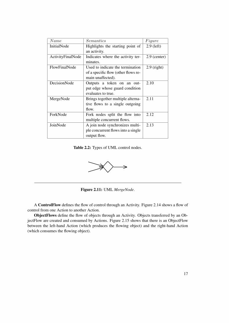
Table 2.2: Types of UML control nodes.
Figure 2.11: UML MergeNode.
A ControlFlow defines the flow of control through an Activity. Figure 2.14 shows a flow ofcontrol from one Action to another Action.
ObjectFlows define the flow of objects through an Activity. Objects transferred by an Ob-jectFlow are created and consumed by Actions. Figure 2.15 shows that there is an ObjectFlowbetween the left-hand Action (which produces the flowing object) and the right-hand Action(which consumes the flowing object).
17

Figure 2.12: UML ForkNode.
Figure 2.13: UML JoinNode.
Figure 2.14: UML Actions connected via a ControlFlow.
Figure 2.15: UML Actions connected via an ObjectFlow.
18

CHAPTER 3Executable UML
This section aims at introducing the reader to the Foundational Subset for Executable UMLModels (fUML). fUML is introduced in greater detail by describing its syntax and semantics.Regarding the syntax of fUML, the Activities and Actions packages are described in furtherdetail. The fUML semantics are described together with a step-by-step textual description onhow the execution engine executes an fUML model. At the end, the built-in model library andthe limitations regarding external libraries are discussed.
3.1 Introduction to Foundational UML
Foundational UML, Foundational UML Subset, or fUML are shorthands for the “Semantics ofa Foundational Subset for Executable UML Models” that represents a standard defined by theOMG [31]. As its name suggests, it is based on a subset of UML (i.e., the metamodel of fUMLis a subset of the metamodel of UML), covering specific parts of it. The goal of this standard isto precisely define the execution semantics of this UML subset. fUML 1.1 (beta 1) [33] has beenreleased in January 2013, and is based on UML 2.4.1 [29] released August 2011, representingthe current version at the time of writing this thesis. The extension of the fUML virtual machinebuilt by Mayerhofer et al. [21] builds upon fUML version 1.0 [31] (released February 2011)based on UML 2.3 [25].
In the specification, the fundamental purpose of fUML is described as being an intermediarybetween UML “surface subsets” used for modeling and computational platform languages usedas the target for model execution (cf. Figure 3.1). To clarify, fUML is an executable UML andnot Executable UML1. fUML deals with two layers of the semantic areas of UML 2 namely thestructural foundations and the behavioral base, as well as with Activities as shown in Figure 1.1in Section 1.1.
1Executable UML, also called xtUML or xUML, as introduced by Mellor and Balcer [23] is a different approachfor specifying the semantics of UML.
19

The “surface UML subset” is translated in a two-step process. First, the surface UML subsetis translated into the “foundational UML subset” since the surface UML subset is typically usedto model a system as it contains a larger amount of modeling concepts than the fUML subset.Second, the fUML subset is translated into a computational platform language such as Java.Furthermore, the computational platform language can then be used to execute the model.
With this in mind, fUML can be seen as an intermediary between the computational platformlanguage and the surface UML subset for modeling a system. fUML has sufficient expressibilityto enable the creation of models, which can then be executed automatically [33]. Hence, thefoundational UML subset is a computationally complete language for executable models thatdefines the execution semantics for the rest of UML in the long run.
Figure 3.1: Translation to and from the foundational UML subset [31].
3.2 Syntax of Foundational UML
The syntax of a modeling language, like fUML, provides rules for how to construct well-formedmodels. In fUML, such well-formed models are presumed to have met all the constraints im-posed by the abstract syntax defined in the UML specification [33]. As described earlier, fUMLmerges packages of the UML 2 superstructure into syntactic packages. Since fUML is struc-tured in the same way as UML because its metamodel is a subset of the UML metamodel, alsotheir packages are structured in the same way. Those UML packages that are included in fUMLmay be object to further restrictions in form of additional constraints and/or excluded elements.Figure 3.2 depicts UML packages that are merged into the foundational UML subset. While thered colored packages, namely Classes, Actions, Common Behaviors and Activities, are included,the black colored packages (i.e., Composite Structures, Deployments, Components, Interactions,State Machines, and Use Cases) are currently (still) excluded from the foundational UML subset.
20

Classes
Componets
Composite Structures
Deployments
Actions
Activities
CommonBehaviors
Interactions
State Machines
Use Cases
UML 2Foundational UML Subset
Modeling of Structure
Modeling of Behavior
Figure 3.2: UML packages merged into the foundational UML subset.
Furthermore, as mentioned in Section 2.3, UML categorizes diagrams into structure dia-grams and behavior diagrams, respectively. On one hand, structure diagrams model the staticstructure and on the other hand, behavior diagrams model the dynamic behavior, of the objectsin a system. fUML contains class diagrams for modeling structure using the Classes packageand activity diagrams for modeling behavior using the packages Common Behaviors, Activities,and Actions. The Activities and Actions packages are discussed in more detail below.
Activities Package
The UML and fUML Activity syntax sub-packages are referred to as UML::Activities in UMLand fUML::Syntax::Activities in fUML, respectively. When looking for UML activity modelingconcepts in the fUML specification one can see that almost all of them are available (cf. Ta-ble 3.1). Exceptions, i.e., excluded modeling concepts, are the SequenceNode, CentralBufferN-
21

ode, and the DataStoreNode. Note that the FlowFinalNode is available starting from fUMLspecification version 1.1.
Category UML modeling concept Available in fUML 1.1
Behavior Activity yes
Executable Nodes
StructuredActivityNode yes
ConditionalNode yes
LoopNode yes
SequenceNode no
ExpansionRegion yes
Object Nodes
ActivityParameterNode yes
ExpansionNode yes
CentralBufferNode no
DataStoreNode no
Control Nodes
InitialNode yes
ActivityFinalNode yes
DecisionNode yes
MergeNode yes
ForkNode yes
JoinNode yes
FlowFinalNode yes
Activity EdgesControlFlow yes
ObjectFlow yes
Table 3.1: UML Activity modeling concepts available in fUML.
Actions Package
The UML and fUML Action syntax sub-packages are referred to as UML::Actions in UMLand fUML::Syntax::Actions in fUML, respectively.
Table 3.2 lists primitive actions supported by fUML version 1.1. Note that the primitiveactions supported by fUML version 1.0 are equal. The table is categorized into object-related,link-related, variable- and structural feature-related, and communication-related actions [13].
22

When examining the table, one can see that none of the variable-related actions is supported byfUML. Therefore, fUML version 1.1 does not directly support variables.
Category UML modeling concept Available in fUML 1.1
Object-related actions
CreateObjectAction yes
DestroyObjectAction yes
ReadSelfAction yes
TestIdentityAction yes
ReclassifyObjectAction yes
ReadIsClassifiedObjectAction yes
ReadExtentAction yes
StartClassifierBehaviorAction yes
StartObjectBehaviorAction yes
Link-related actions
CreateLinkAction yes
CreateLinkObjectAction no
ReadLinkAction yes
ReadLinkObjectEndAction no
ReadLinkObjectEndQualifierAction no
ClearAssociationAction yes
DestroyLinkAction yes
Variable-related actions
AddVariableValueAction no
ReadVariableAction no
ClearVariableAction no
RemoveVariableAction no
Structural featurerelated actions
AddStructuralFeatureValueAction yes
ReadStructuralFeatureAction yes
ClearStructuralFeatureAction yes
RemoveStructuralFeatureAction yes
ValueSpecificationAction yes
Continued on next page
23

Table 3.2 – continued from previous page
Category UML modeling concepts Available in fUML 1.1
Communicationrelated actions
AcceptCallAction no
AcceptEventAction yes
CallBehaviorAction yes
CallOperationAction yes
BroadcastSignalAction no
SendSignalAction yes
SendObjectAction no
ReplyAction no
Other actions
OpaqueAction no
RaiseExceptionAction no
ReduceAction yes
UnmarshallAction no
Table 3.2: UML Actions available in fUML.
3.3 Semantics of Foundational UML
A natural language, or a language in general meaning, represents a symbolic means for com-munication that provides rules that evolved socially and neurologically over time [33]. Whilestatements constructed using such languages communicate some specific meaning, statementsconstructed using a formal language have a more precise meaning. In a formal language, likefUML, rules are constructed artificially and statements need to be correctly constructed andwell-formed as they serve some intended purpose. Thus, the semantics of a formal languageprovides the specification of the meaning of well-formed statements.
Foundational UML Execution Model, Execution Engine, and Execution Environment
In fUML, the execution model is itself an executable, object-oriented, fUML model of an ex-ecution engine that specifies how fUML models are to be executed. Since every user-definedbehavior in fUML is an activity, also the behavior of the execution model could be defined byactivity diagrams. However, in the fUML specification, the behavior of the execution modelis textually defined in the Java programming language to avoid using enormously large (butequivalent) diagrams. It is important to note that static semantics (i.e., constraints on the well-
24

formedness of fUML models) are not part of the execution semantics since meaning can onlybe assigned to models that are well-formed. The execution model is composed of the followingpackages:
• The Loci package with its sub-packages LociL1, LociL2, and LociL3 specifies the execu-tion engine and its environment for executing fUML models.
• The structural semantics definition in the Classes package.
• The behavioral semantics definition in the CommonBehaviors, Activities, and Actionspackages.
<<import>>
Basic�Behaviors(from�Syntax::CommonBehaviors)
Kernel(from�Semantics::Classes)
import
Loci�L1Kernel(from�Syntax::Classes)
<<import>><<import>>
iBasic�Actions
(from�Semantics::Actions)
Intermediate Actions
Basic�Actions(from�Syntax::Actions)
Intermediate Actions Loci L2
<<import>> <<import>>
<<import>>
Intermediate�Actions(from�Semantics::Actions)
Intermediate�Activities(from Semantics::Activities)
Intermediate�Actions(from�Syntax::Actions)
Intermediate�Activities(from Syntax::Activities)
Loci�L2<<import>> <<import>>
<<import>> <<import>>
<<import>>
(from�Semantics::Activities)
Complete�Actions(from�Semantics::Actions)
(from�Syntax::Activities)
Complete�Actions(from�Syntax::Actions)
<<import>> <<import>>
Complete�Structured�Activities(from�Semantics::Activities)
Complete�Structured�Activities(from�Syntax::Activities)
Loci�L3<<import>> <<import>>
Extra�Structured�Activities(from�Semantics::Activities)
Extra�Structured�Activities(from�Syntax�::Activities)
<<import>> <<import>>
Figure 3.4: Dependencies of the Loci packages to other fUML packages [20]
31
Figure 3.3: The fUML Loci sub-packages with their dependencies [33].
The execution engine in fUML is represented by the Executor class in LociL1 andprovides the operations execute, evaluate and start. At the Locus instances of the
25

class ExtensionalValue can be created during the execution of an fUML model that rep-resent the output of an activity execution. When looking more carefully at Figure 3.3, onecan see that the Locus class basically represents the center of the package as it containsthe other classes ExtensionalValue, Executor, and ExecutionFactory. There-fore, ExtensionalValues may exist prior and after the execution of an activity. TheExecutionFactory is used to instantiate visitor classes. A visitor class is a class that existsfor every metaclass of the abstract syntax of fUML and specifies the behavior for that particularmetaclass of fUML.
In general, the visitor design pattern basically allows to add functions to classes withoutmodifying the classes themselves but instead creating specialized classes with additional func-tions. In fUML, the following types of visitors are distinguished:
• An instance of the Activation visitor class models the semantics of a specific kind ofactivity node.
• Instances of the Evaluation visitor class evaluate a specific kind of value specificationby returning an instance of the value like, for example, denoted by a LiteralIntergervalue specification. Therefore, an abstract syntax metaclass, such as LiteralInteger,can be evaluated by its respective evaluation visitor class, likeLiteralIntegerEvaluation.
• For every concrete subclass of Behavior in the fUML subset there exists a correspond-ing Execution visitor class that is used to execute its specific kind of behavior. Forexample, the behavior of the Activity class can be executed by instantiating its corre-sponding visitor class ActivityExecution.
In addition, the ExecutionFactory provides a list of built-in primitive types (see Ta-ble 3.3) that have their corresponding literal value specifications. Whenever the literal valuespecification is evaluated, its corresponding evaluation class is looked up by its name and at-tached to a resulting value. Note that the fUML specification version 1.0 did not yet include theReal primitive type.
The Executor class extends the FumlObject class and provides the following opera-tions:
1. The evaluate operation evaluates a value specification (as e.g., LiteralString) by re-turning the specified value.
2. The execute operation takes several input parameters, synchronously executes a behav-ior in the context of a provided fUML object, and then returns output values.
3. The start operation is used to asynchronously start the execution of a behavior andreturns a reference to the instance of the executing behavior.
In order to build-up the execution environment to execute fUML models, the followingcomponents are required [33]:
26

1. An instance of the Locus class.
2. An instance of the Executor class that is linked to the previously mentioned Locusobject.
3. An instance of the ExecutionFactory class, also linked to the same Locus object.
4. An instance of the PrimitiveType class for each primitive type (i.e., Integer, Real,Boolean, String, and UnlimitedNatural) linked to the previously created ExecutionFactory.
5. An instance of a strategy class (i.e., ChioceStrategy, DispatchStrategy, andGetNextEventStrategy) also linked to the same ExecutionFactory.
Foundational UML Activity Execution
In order for the execution engine to execute an fUML model (i.e., an UML activity), the follow-ing five steps are performed by the engine [20]:
1. Initially, before the actual execution of the activity is started, activity input parameternodes are supplied with input.
2. As a next step, still before the actual activity execution, the execution engine identifiesenabled nodes. Activity input parameter nodes, initial nodes, control nodes, and actionswith no incoming edges build the set of enabled nodes.
3. After the set of enabled nodes is determined, every enabled node is supplied with acontrol token.
4. When an enabled node is supplied with tokens, the execution of the activity node begins.
a) Determine if activity node execution prerequisites are fulfilled. Execution pre-requisites of an activity node are that each of its incoming control flow edge is sup-plied with a control token and each of its input pins is supplied with the minimalnecessary object tokens.
b) In case all prerequisites of an activity node are fulfilled (i.e., the activity node isready to be executed), available control tokens and object tokens are consumed.“Consuming tokens” means that tokens are moved from the providing activity nodeto the activity node itself.
c) Right after tokens are moved to the activity node itself (i.e., they are “consumed” bythe activity node), the behavior execution of the activity node is triggered. In thisstep, whenever the activity node is an action (e.g., CreateObjectAction), output pinsmay need to be supplied with output in form of object tokens.
27

d) After the behavior execution of the activity node has been carried out and eventuallyexisting output pins are supplied with object tokens (i.e., in case the activity node isan action), tokens are sent to subsequent activity nodes. In detail, every outgoingcontrol flow edge is supplied with a control token that is sent to the target of thecontrol flow edge. Additionally, in case of outgoing object flow edges (i.e., if theactivity node is an action), the object tokens previously supplied at the output pinsare sent to the target input pin of the subsequent activity node.
e) Next, after the behavior execution of the activity node (including the sending oftokens to their destination), it is determined if the same activity node is supposedto be executed again. In case an activity node should be executed again, the stepsfrom a to e are repeated for the same activity node.
f) Subsequently, activity nodes supplied with tokens by the previously executed ac-tivity node may be executed if they are ready (i.e., their prerequisites are fulfilled).In case a subsequent activity node is ready to be executed, the steps a to e are per-formed on that particular node.
5. At the end of the activity execution (i.e., when no activity node can be executed anymore),the activity output parameters are supplied with output values which have been estab-lished during the execution of the activity.
3.4 Foundational Model Library
The fUML Model Library or Foundational Model Library is the only library, in the fUML spec-ification, and contains user-level model elements which can be referenced in fUML models.
The PrimitiveTypes package, which is imported by the PrimitiveBehaviors package in thefUML Model Library, is provided by the UML 2 Infrastructure Specification [29]. Hence, inuser models those types can also be directly referenced. Table 3.3 describes the value domainsof the primitive types provided by fUML. For these types, corresponding literal values can bespecified in fUML as long as they are all registered with the ExecutionFactory at every Locus.
The PrimitiveBehaviors package contains a set of primitive behaviors that provide operationson the primitive data types. This set of primitive behaviors is composed of IntegerFunctions,RealFunctions, BooleanFunctions, StringFunctions, UnlimitedNaturalFunctions, and ListFunc-tions. These behaviors may be called from user models using the CallBehaviorAction.
The Common sub-package of the fUML Foundational Model Library contains classifiers thatare currently only used in the basic input/output model of the fUML specification but they areconsidered to be usable in a wider context in the future [33].
The basic input/output library (i.e., the BasicInputOutput sub-package) builds upon a chan-nel model that regards the executing model as a “closed universe” [33]. This means that inputand output requires an opened channel to this closed universe where the actual source or tar-get is not known. Therefore, while the input channel provides a means for an executing model
28

Type Description
Integer An Integer can have literal values in the signedset of integers (...-2, -1, 0, 1, 2...). The set is the-oretically infinite but the conforming implemen-tations may limit the supported values to a finiteset.
Real The Real type has been first introduced in fUMLSpecification Version 1.1. It represents literalvalues in the infinite, continuous set of real num-bers. Also here, the conforming implementationmay limit the set to be finite.
Boolean The primitive type Boolean has the two literalvalues true and false.
String Strings can have literal values that are a sequenceof zero or more characters with maximum sizebeing unbound. Note that the fUML specificationdoes not define the character set of this type.
UnlimitedNatural The UnlimitedNatural type has literal values likeInteger but only the non-negative (0, 1, 2...) partof them.
Table 3.3: Primitive types in fUML specification version 1.1 [33].
to receive values from outside, the output channel sends values from the executing model tothe outside. In addition, those channels need to be made available as services at the currentexecution locus. The idea behind the basic input/output model is based on providing textual in-put/output as well as file input/output that is external to the execution model. The primary goalof the BasicInputOutput library is to provide a simple semantic foundation for what it means toreceive input to and send output from an executing model.
fUML Limitations Regarding External Libraries
As mentioned earlier in this chapter, the Foundational Model Library provides basic support foruser-level model elements that can be referenced in an fUML model. It basically contains a setof primitive types (PrimitiveTypes package), primitive behaviors for these primitive types(PrimitiveBehaviors package) and a basic input/output library (BasicInputOutputpackage). The functions made available by the Foundational Model Library are indeed on abasic level. To be more precise, the available functions are bound to primitive data types, e.g.,the integer function library includes a function to subtract two integer values. The FoundationalModel Library does do not include a mechanism to reuse existing Java APIs.
29

For this purpose, one could alternatively implement domain-specific model libraries thatbasically mimic the functionality provided by currently existing Java libraries. To be moreprecise, for every operation that is intended to be used, one needs to overwrite the OpaqueBehaviorExecution class and register the class using the addPrimitiveBehaviorPrototype method in the ExecutionFactory class. Additionally, an fUML model con-taining the intended OpaqueBehavior has to be created and called using a CallBehaviorAction. Alternatively to the latter, some kind of a library UML model, containing the intendedOpaqueBehavior, can be referenced. Implementing domain specific model libraries requiresan extensive amount of work that might only be feasible within a community as large as theexisting Java open source community.
With the available capabilities of the fUML Foundational Model Library a modeler cannotuse and benefit from the full power of the target GPL, such as Java. If the modeler would begranted full access to GPL libraries and third party libraries, she or he could use huge, alreadyimplemented, applications and APIs to speed up development time and benefit from alreadywell-tested modules. Rapid software development, as it is done nowadays by making use ofexternal libraries, is hindered by the inability to use those libraries. If developers do not escapethe borders of the fUML virtual machine they will not gain from the benefits provided by externallibraries. Integrating external libraries into the fUML Foundational Model Library would requirea huge amount of effort as is requires writing source code for every single function of a libraryto make it available to the modeler. The latter approach and similar approaches are shortlydiscussed in Section 9.2. An overview on our approach proposed for supporting the access toexternal Java libraries in fUML models that does not require any programming effort at all isprovided in Chapter 4.
30

CHAPTER 4Overview on the Foundational UML
Library Support
Within the scope of this chapter a conceptual overview over the proposed approach for the inte-gration of external libraries into fUML is given. Moreover, each of the four steps required to betaken to execute an activity model referencing an external library is briefly explained.
In the subsequent chapters the entire approach is divided into parts and each part is describedby a specific chapter. Namely, Chapter 5 presents how a library can be reverse engineered; Chap-ter 6 shows how fUML activity models that reference classes and operations of external librariesare built; and Chapter 7 presents how the created artifacts are used by the Integration Layer inorder to execute the fUML activity model that accesses an external library.
4.1 Introduction to the Integration Layer Concept
The initial concept of the Integration Layer, implemented within this work, was proposed in thepaper “Towards xMOF: Executable DSMLs based on fUML” authored and presented by May-hofer et al. [22] during the 12th Workshop on Domain-Specific Modeling in Tucson, Arizona,USA.
The paper presents the existence of a major drawback that results from the fact that modelersmay not escape the boundaries of the fUML virtual machine. To be more precise, in fUML mod-els, external libraries providing extensive capabilities to quickly create sophisticated models andthus applications cannot be used. Mayerhofer et al. propose the approach of integrating requiredclasses of the external libraries into the fUML model and to employ a dedicated IntegrationLayer during runtime.
Since, by re-using software components one is able to improve quality and increase pro-ductivity as concluded by several studies [15], re-using software components within the scope
31

of fUML models in form of external libraries might also decrease the number of defects andspeed-up the modeling process.
The Integration Layer prototype, developed during the course of this work, is based on thefUML virtual machine prototype by Mayerhofer et al. [20]. The fUML virtual machine pro-totype allows the execution of fUML models based on the fundamental principle of UML’ssemantics, which is that every system behavior is ultimately expressed and hence caused by asequence of actions. Their prototype has been built upon the reference implementation of thefUML standard execution semantics1 to interpret fUML models. However, the fUML modelinterpreter is not able to access resources, such as classes or operations, from external libraries -that is where the Integration Layer prototype comes into play.
The Integration Layer concept proposes an approach of re-use existing libraries by extendingthe capabilities of the current fUML virtual machine implementation. In particular, by re-usingexisting libraries modeling complete applications using fUML becomes more feasible. Sim-ple jobs such as sending e-mails or accessing an in-memory database, that previously were notpossible, could be as simple as an operation call in a traditional GPL. The operation call to anexternal library then handles all required details necessary to finally send an e-mail or retrievedata coming from a database. Therefore, the modeler does not need to reason about how the e-mail is sent but only about which operation is necessary to be called in order to send the e-mailand create the model accordingly. As a result, the Integration Layer releases the modeler fromtrying to re-implement the functionality provided by the existing library.
The goal of the Integration Layer is to be capable of invoking operations of external librariesusing a CallOperationAction during the execution of the fUML model. Within this work,an external operation refers to an operation located in an external library. When the return valueof the external operation call has been retrieved, the Integration Layer translates the Java valueinto an fUML value and integrates the value into the fUML runtime model. Equally important,these values can be either primitive, such as int, boolean, or String, or complex, i.e., ofany type. Moreover, also operation input parameters can be primitive and complex. While anoperation can return only a single parameter at any point in time, it can certainly receive multi-ple input parameters. Multiple different cases of such external operation calls by executing anfUML CallOperationAction arise. Possible cases are discussed within Chapter 7.4 alongwith which of them have been realized in the Integration Layer prototype.
Furthermore, the proposed Integration Layer allows to create and modify instances of ex-ternal library classes. As a result of that, potential changes made by external operation calls onJava objects and changes made by actions on fUML objects need to be taken into considerationwhen the same objects are reused at a later point in time. Otherwise, if those changes would notbe taken into account, potentially unwanted side effects might occur. As a simple example, con-sider an object of type Clock with a primitive integer field secondOfHour having the value “10”assigned to it. An initial operation call to get the secondOfHour field might return “10”. Then,
1The reference implementation of the fUML standard execution semantics can be found online at http://portal.modeldriven.org/content/fuml-reference-implementation-download.
32

after translating the Clock Java object into a corresponding fUML object and re-using the fUMLobject at a later point in time during the model execution without considering changes that mighthave been done to the corresponding Java object in the meantime might result in an undesiredside effect done to the application. To finish the simple example, the secondOfHour field withthe value “10” used within the fUML execution environment 5 seconds later still contains “10”instead of “15” like its corresponding Java object.
The approach or strategy to execute an fUML model referencing an external library using theIntegration Layer prototype consists of four general steps which are described in the following.Figure 4.1, 4.2, and 4.4 illustrate the approach graphically and Listing 4.1 depicts the practicalrealization of step 4.
4.2 Reverse Engineering of External Libraries
Initially, before the actual integration of an external library at runtime can occur, the classesprovided by that external library first need to be imported into the fUML model. In order toimport classes of the external library, the library needs to be reverse engineered with a reverseengineer tool such as MoDisco.
The external library chosen to be used by the fUML model to be executed, has to be reverseengineered into a UML class model. The reverse engineering process, as described in Chapter 5in more detail, typically requires access to the library’s source code. Specifically, when usingthe Eclipse MoDisco reverse engineering tool, the Java source code contained within the projectto be reverse engineered is used to establish the UML class model. Accordingly, the UML classmodel gained from the Java source code reflects the project’s structure. In this case, the reverseengineered Java project represents the external library to be used in the upcoming steps. Addi-tionally, the Java project is packed into a Java Archive file (also called JAR file) that aggregatesall the Java project files into one file that is often used to represent a Java library. To summarize,from the artifacts created within this step there are two files, namely the JAR file representingthe external library itself and the UML class model representing the external library structure,used in the forthcoming steps.
On the other hand, when using the Eclipse Jar2UML tool, an existing JAR file can be usedto build an UML class model representing the external library. The Eclipse Jar2UML tool takesa JAR file as input and produces a UML class model as output that represents the library’s struc-ture. Finally, when using this strategy, the JAR file and the generated UML class model file areused in the next steps.
Figure 4.1 visualizes this first step. In this step, existing library source code is used to gener-ate the library’s corresponding JAR and UML class model file. In more detail, a library’s JAR filecan be generated within Eclipse by right-clicking on the Java project and selecting “Export...”and then choosing “JAR file” in the wizard. Alternatively, it can be retrieved from an existingrepository. Furthermore, it is important to mention that the UML class model can be generatedin different ways. One possibility of generating the UML class model out of existing librarysource code is by using the Eclipse MoDisco reverse engineering tool. The Eclipse Jar2UML
33

«executionEnvironment,Java Runtime Execution Environment»
Email.java
SimpleEmail.java EmailAttachment.java
Library source files
Library packed into a Java Archive (JAR) file
«abstract»Email
- message :MimeMessage- subject :String- toList :List
+ addTo(String) :Email+ send() :String+ setMsg(String) :Email+ setSubject(String) :Email
SimpleEmail
+ setMsg(String) :Email
EmailAttachment
+ ATTACHMENT :String+ INLINE :String
+ getName() :String+ getPath() :String+ getURL() :URL+ setName(String) :void+ setPath(String) :void+ setURL(URL) :void
UML class model file
UmlActivity1ActivityInitial
Fork1
ActivityOutput
Defined UML activity model file referencing an external library (i.e. the preparered UML classmodel)
Defined UML activity model file referencing an external library (i.e. the preparered UML classmodel)
CreateObjectAction1CreateObject
CallOperationAction1(::)
CallOperationAction2(::)
«fUML.Syntax.Activities.IntermediateActivities.Activity»fUmlActivity1
«org.eclipse.uml2.uml.Activity»umlActivity1
With "Classifier" attribute equal to root::model::package1::Class1
With "Operation" attribute equal to root model::package1::Class1::operation1
Final
References the prepared UML class model that depicts the structure of the externallibrary
UmlActivity1.uml
ObjectFlow3
MoDisco: reverseengineer sourcefiles to UML classmodel
Jar2UML: reverseengineer JAR to UMLclass model
ObjectFlow1
Eclipse: exportas JAR file
ObjectFlow2_2
Obtain resource from file system
org.modelexecution.fuml.convert.uml2.UML2Converter().convert( umlActivity1 )
org.modelexecution.fuml.extlib.IntegrationLayer.getExecutionContext().execute( fUmlActivity1, ... )
ObjectFlow2_1
Figure 4.1: Reverse engineering the external library (step 1).
34

tool provides another way for generating a UML class model file. Specifically, it does so byusing the library’s Java Archive file.
4.3 Preparation of Library UML Models
Although, the outcome of the reverse engineering process using the MoDisco tool is a dedicatedUML class model that represents an interface to its corresponding reverse engineered library, itdoes not contain enough information for the Integration Layer to be able to, for example, locatethe classes and operations provided by the library. For this purpose, the file path to the JavaArchive (JAR) is stored within the UML class model as a UML comment.
In order to do so, the UML2Preparer is used to create a so-called placeholder activityfor each operation of each class contained by the reverse-engineered UML class model of theexternal library. Placeholder activities are created because reverse engineering tools are notcapable of representing library behavior in the models they create. First, placeholder activitiesallow the Integration Layer to identify library operations, and proceeding that, to interrupt theexecution. To be more precise, during the latter interruption the Integration Layer forwards theoperation call to the actual library method, obtains the result, and re-integrates the result intothe fUML runtime model. For the fUML model to stay executable, every operation created bythe reverse engineering tool needs to have a corresponding method in form of an fUML activity(i.e., placeholder activity).
Further, in order to differentiate elements in a UML activity model that reference classesand operations that are external to the model from those that are not, is to somehow flag themas external. There are several ways of flagging or marking an element in a UML class model. Apossibility of doing so is given by adding a UML comment element to the element in question.That UML comment element will need to contain a value that is consistent over all as externalflagged elements. Therefore, the Integration Layer can identify classes and operations that areexternal from those that are not by examining the element for the existence of the consistentpre-defined comment.
One of the two artifacts gained in step 1, namely the UML class model, is exclusively used inthis step as input for the UML2Preparer. To be more precise, the UML2Preparer, created withinthe scope of this work, reads the UML class model file and produces a modified copy of it inorder to fulfill the Integration Layer prototype requirements. The Integration Layer prototyperequirements include the provision of the information of whether a class or operation refers toan external library class or operation and where the appropriate external library (i.e., the JARfile) is located. A more detailed description on the UML2Preparer can be found in Chapter 6.1.In summary, the outcome produced by the UML2Preparer is another UML class model, alsoreferred to as prepared UML class model, containing additional information about the librarywhose structure it represents. The additional information is also composed of placeholder activ-ities representing stubs for library behavior.
Step 2 is visualized in Figure 4.2. Particularly, the UML class model generated in step 1is reconsidered and put through a customization process performed by the UML2Preparer. In
35

«abstract»Email
- message :MimeMessage- subject :String- toList :List
+ addTo(String) :Email+ send() :String+ setMsg(String) :Email+ setSubject(String) :Email
SimpleEmail
+ setMsg(String) :Email
EmailAttachment
+ ATTACHMENT :String+ INLINE :String
+ getName() :String+ getPath() :String+ getURL() :URL+ setName(String) :void+ setPath(String) :void+ setURL(URL) :void
UML class model file
Prepared UML class model file
«abstract»Email
- message :MimeMessage- subject :String- toList :List
+ addTo(String) :Email+ send() :String+ setMsg(String) :Email+ setSubject(String) :Email
Contains UML Comment:"@external=PATH_TO\commons-email-1.3.1.jar"
SimpleEmail
+ setMsg(String) :Email
EmailAttachment
+ ATTACHMENT :String+ INLINE :String
+ getName() :String+ getPath() :String+ getURL() :URL+ setName(String) :void+ setPath(String) :void+ setURL(URL) :void
UML2Preparer: prepare UML class model for the Integration Layer
Figure 4.2: Preparing the UML class model (step 2).
36

more detail, the UML2Preparer functionality can either be utilized by its dedicated graphicaluser interface or by creating an instance of its Java class. In case its graphical user interface isused, the user needs to specify various file locations such as of the library JAR file, the inputUML class model representing the library’s structure, and the location where the output UMLclass model should be stored. In case the library JAR file itself depends on other JAR file(s),those files can also be added to the list of required Java Archives. In the other case, if an in-stance of the UML2Preparer class is created, specific operation calls can be made to provide theUML2Preparer instance with the resources required to perform the preparation process. Thus,after the preparation process has been performed, a new UML class model file is created at thespecified location in the file system.
The prepared UML class model, differs from the reverse engineered original model in sev-eral ways. In summary, its classes and operations are marked as referring to an external libraryand supplied with information regarding where their corresponding Java Archive file is located.Additionally, for every operation in the UML class model, a corresponding placeholder activityis created. A more detailed description on the UML class model preparation process can befound in Section 6.1.
4.4 Definition of UML Models Referencing External Libraries
In this step, the modeler specifies the UML model that references the previously mentioned ex-ternal library. He or she can do so by loading the prepared UML class model file within theEclipse UML2Tools Editor as an additional resource. Chapter 6.3 describes the process of mod-eling a UML model referencing an external library by example. An instance of a class froman external library can be created by modeling a CreateObjectAction having its “Classifier” at-tribute referencing the external class. Equally important, to allow instances of those objects toflow between nodes, Pins and ObjectFlows between them need to be created. Furthermore, anexternal operation call can be made by defining a CallOperationAction with its “Operation” at-tribute referencing the external library operation.
Figure 4.3 shows a UML model, that references an external library by referencing the cor-responding prepared UML class model. This UML model has been modeled by the modeler instep 3 using, for example, the Eclipse UML2Tools Editor.
37

«executionEnvironment,Java Runtime Execution Environment»
Email.java
SimpleEmail.java EmailAttachment.java
Library source files
«abstract»Email
- message :MimeMessage- subject :String- toList :List
+ addTo(String) :Email+ send() :String+ setMsg(String) :Email+ setSubject(String) :Email
SimpleEmail
+ setMsg(String) :Email
EmailAttachment
+ ATTACHMENT :String+ INLINE :String
+ getName() :String+ getPath() :String+ getURL() :URL+ setName(String) :void+ setPath(String) :void+ setURL(URL) :void
UML class model file
MailActivity
transmissionReceipt : String
mail::SimpleEmailCreateObject
result : SimpleEmail
mail::Email::setMsg(::)msg : String
target : SimpleEmail
mail::Email::send(::)target : SimpleEmail
«fUML.Syntax.Activities.IntermediateActivities.Activity»fUmlActivity1
«org.eclipse.uml2.uml.Activity»umlActivity1
Final
UmlActivity1.uml
MessageValueSpecification
msg : String
Fork
mail::Email:setTo(::)to : String
target : SimpleEmail
RecipientValueSpecification
to : String
org.modelexecution.fuml.extlib.IntegrationLayer.getExecutionContext().execute( fUmlActivity1, ... )
org.modelexecution.fuml.convert.uml2.UML2Converter().convert( umlActivity1 )
Obtain resource from file system
Reverse engineering with tool of choice (e.g.,Eclipse MoDisco or Jar2UML)
Figure 4.3: Modeling the UML activity model referencing the ApacheMail external library (step3).
4.5 Execution of UML Models Referencing External Libraries
After step 3 has been completed, all artifacts required for the execution of the defined UMLmodel have been established. To summarize, the required artifacts include the UML model tobe executed, the prepared UML class model, the library’s Java Archive, and Java Archives onwhich the library depends. Having that in mind, initially, the UML model that shall be executedhas to be converted into an fUML model by the moliz UML2Converter. After the model hasbeen successfully converted into an fUML model, it can finally be executed by handing it overto the Integration Layer.
The Integration Layer itself uses the fUML virtual machine prototype developed by May-erhofer et al. in order to execute a UML activity. More specific, the fUML model is passedto the Execution Context. During the execution, whenever references to external library oper-ations are encountered, the Integration Layer calls the referenced operation and integrates theresulting outcome (i.e., the return value) into the fUML runtime model. Furthermore, in casethe fUML model references an external library class in a CreateObjectAction, the IntegrationLayer instantiates the external library class and integrates the Java object instance in form ofan fUML object into the fUML runtime model. Whenever the execution has been completed,the Execution Context’s Locus can be examined for any residing fUML objects created duringthe execution. Additionally, the Integration Layer keeps track of events occurring during theexecution such that the output parameter value of a specific event can be retrieved.
For a better comprehension of step 4, the UML activity model execution, consider comparingFigure 4.4 and Listing 4.1.
Initially, an instance of the Integration Layer is created and the UML activity is loadedfrom the file system (listing line 5). In order to do so, the loadActivity method located inthe IntegrationLayer is called by passing the file path of the external library UML classmodel, the file path to the UML model containing the activity to be executed, and the activity’sname.
38

libra
ryM
odel
:Stri
ng
activ
ityN
ame
:Stri
ng
umlM
odel
:Stri
ng
libra
ryM
odel
:Stri
ng
activ
ityN
ame
:Stri
ng
umlM
odel
:Stri
ng
load
act
ivity
(Inte
grat
ionL
ayer
::loa
dAct
ivity
)
aciv
ityN
ame
:Stri
ng
libra
ryM
odel
:Stri
ng
umlM
odel
:Stri
ng
umlA
ctiv
ity :
org.
eclip
se.u
ml2
.um
l.Act
ivity
inte
grat
ionL
ayer
crea
te c
onve
rter
Cre
ateO
bjec
t
uml2
conv
erte
r :or
g.m
odel
exec
utio
n.fu
ml.
conv
ert.u
ml2
.UM
L2C
onve
rter
conv
ert a
ctiv
ity(U
ML2
Con
verte
r::co
nver
t)um
lAct
ivity
fum
lAct
ivity
:fU
ML.
Syn
tax.
Act
iviti
es.
Inte
rmed
iate
Act
iviti
es.A
ctiv
ityum
l2co
nver
ter
read
inte
grat
ion
laye
r
Rea
dSel
f
inte
grat
ionL
ayer
:or
g.m
odel
exec
utio
n.fu
ml.
extli
b.In
tegr
atio
nLay
er
get e
xecu
tion
cont
ext
(Inte
grat
ionL
ayer
::get
Exe
cutio
nCon
text
)in
tegr
atio
nLay
erex
ecut
ionC
onte
xt :
org.
mod
elex
ecut
ion.
fum
ldeb
ug.
core
.Exe
cutio
nCon
text
exec
ute
activ
ity(E
xecu
tionC
onte
xt::e
xecu
te)
exec
utio
nCon
text
fum
lAct
ivity
Figure 4.4: Executing the UML activity model referencing an external library (step 4).
39

Next, an instance of the moliz UML2Converter is created and used to convert the activityinto a corresponding fUML activity (listing line 8 and 11). At this point, the Execution Contextresiding inside the Integration Layer can be used to execute the previously created fUML activityas shown in listing line 14. Finally, by retrieving the Execution Context’s Locus, any residingfUML object, created during the execution, can be examined (listing line 17 and 20).
Moreover, by using the “getOutputParameterValue” method provided by the Inte-gration Layer, the output parameter value of a specific event that occurred during the execu-tion can be retrieved as shown in listing line 23 and 26. Such an event can be, for example,an ActivityEntryEvent, ActivityExitEvent, ActivityNodeEntryEvent, orActivityNodeExitEvent. Using the functionality provided by this method one can, forexample, retrieve the ParameterValue that has been produced by executing a specific nodewithin an activity or the entire activity itself.
40

Lis
ting
4.1:
Exe
cutin
gth
eU
ML
activ
itym
odel
refe
renc
ing
anex
tern
allib
rary
usin
gth
eIn
tegr
atio
nL
ayer
(ste
p4)
.1
//CreatinganewIntegrationLayerinstance
2org.modelexecution.fuml.extlib.IntegrationLayerintegrationLayer=
newIntegrationLayerImpl();
3 4//LoadingaspecificUMLactivityfromaUMLmodelstoredinthefilesystem
5org.eclipse.uml2.uml.ActivityumlActivity=integrationLayer.loadActivity("path\to\libraryModel.uml",
"Activity1","path\to\umlModel.uml");
6 7//InstantiatingtheMolizUML2Converter
8org.modelexecution.fuml.convert.uml2.UML2Converteruml2Converter=
newUML2Converter();
9 10//ConvertUMLactivityintofUMLactivityusingtheUML2Converter
11fUML.Syntax.Activities.IntermediateActivities.ActivityfUMLActivity=uml2Converter.convert(umlActivity).
getActivities().iterator().next();
12 13//HandthefUMLactivityovertotheIntegrationLayer’sExecutionContextforexecution
14integrationLayer.getExecutionContext().execute(fUMLActivity,
null,
newParameterValueList());
15 16//ObtainingtheIntegrationLayer’sExecutionContext’sLocus
17Locuslocus=integrationLayer.getExecutionContext().getLocus();
18 19//ObtaininganexpectedfUMLObjectfromtheLocus
20Object_fUmlObject=(Object_)locus.extensionalValues.get(0);
21 22//ObtainingtheActivityOutputinformofanfUMLParameterValue
23ParameterValueoutputParameterValue=integrationLayer.getOutputParameterValue("ActivityNodeEntryEvent","
LastActionInActivity1");
24 25//IncaseaStringoutputparametervalueisexpected,itcanbeobtainedinthefollowingway
26StringoutputValue=((StringValue)outputParameterValue.values.get(0)).value;
41

CHAPTER 5Reverse Engineering of Java Libraries
In this chapter the reader is introduced with the process of reverse engineering software andpresents the Eclipse MoDisco model discovery tool. In detail, it describes the principles ofmetamodel-driven discovery as well as the architecture, existing components, and migrationchains of MoDisco. Additionally, a short introduction to the ATLAS Transformation Languageis provided to help understand model-to-model transformation processes. The second part of thechapter provides an example that shows how a Java application can be reverse engineered into aUML class model.
5.1 Introduction to Reverse Engineering
“Reverse engineering is the process of analyzing a subject system to create representations ofthe system at a higher level of abstraction.” [5]. Ideally, the reverse engineering process out-put is a model that allows to analyze, understand, and even re-generate a refactored version ofthe system. This is where Model-Driven Reverse Engineering (MDRE) comes in by providingmodel-based views on systems that help understand the existing system [3]. The goal of thereverse engineering part of this thesis is to obtain a UML class diagram representation of a Javaapplication that describes the structure of the reverse engineered application. In order to achievethis goal, the Eclipse Model Driven Technology (MDT) project MoDisco1 has been taken intoaccount as it already provides several model discoverers, generators, and transformations. Alter-natively, to immediately create a UML class model out of a Java Archive, the Eclipse Jar2UMLtool can be used2.
1The Eclipse MoDisco project is available online at http://www.eclipse.org/MoDisco/. AccessedFebruary, 2014.
2The Eclipse Jar2UML tool, developed by the Software Languages Lab within the Department of ComputerScience of the Vrije Universiteit Brussel, is available online at http://soft.vub.ac.be/soft/research/mdd/jar2uml. Accessed January, 2014.
43

5.2 Reverse Engineering Using MoDisco Model Discovery Tool
MoDisco stands for Model Discovery and is an Eclipse Generative Modeling Technology (GMT)compontent for model-driven reverse engineering. In more detail, it is an extensible frameworkto develop model-driven tools to support use cases of software modernization (i.e., extractingmodels from legacy systems and use them on modernization use cases). MoDisco has been ini-tially funded by the European Community in the context of the IST European MODELPLEXresearch project in 2007. The objective of the research project was to provide open, model-drivensolutions for complex systems engineering. The plan of MODELPLEX was to deliver solutionsfor knowledge discovery (i.e., how to create models out of existing heterogeneous systems tohandle their complexity) under the lead of Sodifrance and AtlanMod in a French laboratoryfounded by Jean Bézivin [38]. The AtlanMod research team, already involved in several Eclipsemodeling projects such as ATL and AMW3, proposed to launch MoDisco, a new Eclipse-basedproject that should serve as a reference platform for legacy modernization tools dedicated toreverse engineering.
In this work we are specifically interested in the reverse engineering capabilities of theMoDisco tool. Since MoDisco goes beyond reverse engineering, its architecture will be shortlydescribed together with a more in-depth description of how models are extracted from Javasource code using components that are already included in MoDisco.
MoDisco proposes an extensible model-driven approach to model discovery that is generic.This means that Eclipse contributors can develop their own solutions to discover models in dif-ferent legacy systems thanks to the framework provided by MoDisco. In particular, the MoDiscoframework includes a set of guidelines together with several OMG standards implementationssuch as the Structured Metrics Metamodel (SMM) [34] or the Knowledge Discovery Metamodel(KDM) [27]. Since MoDisco is an Eclipse component it can integrate with Eclipse technologiesor plug-ins like those of the Eclipse Modeling Project such as model-to-model transformations(like, for example, ATL), Eclipse Modeling Framework (EMF), Graphical Modeling Framework(GMF), and others.
In conclusion, MoDisco provides a platform to extract knowledge from existing applications,transform this knowledge into new architecture and paradigms, and to regenerate the applica-tion according to specific patterns and technical platforms that are more reusable and flexible.It does so by providing an open and therefore extensible framework that contains model-drivenreverse-engineering components and tools.
Metamodel-Driven Discovery
Model discovery is based on a metamodel-driven approach such that every step is guided bya metamodel [38]. The metamodel-driven discovery approach is shown in Figure 5.1. Conse-quently, at the beginning of the discovery process, a metamodel defining the modeling language
3AMW stands for ATLAS Model Weaving, a model weaving technology.
44

for models to be discovered, has to be defined. In the next step, one or multiple discoverer toolsare built that extract all the necessary information from the existing system and build a modelthat conforms to the metamodel defined in the first step. Ideally, those discoverers come with themetamodel, if not they might be partially generated from the syntax description of the files tobe discovered. Alternatively, the discoverer reuses an existing component to extract informationsuch that a model can be created. In conclusion, the output of the discovery process is a model(e.g., in XMI4 format) conforming to a dedicated metamodel.
Figure 5.1: Metamodel-driven discovery approach [38].
MoDisco Architecture
MoDisco’s architecture is split into three basic layers to facilitate the reuse of components be-tween several use cases. Figure 5.2 illustrates the three-layer architecture of MoDisco.
The Use Cases Layer contains components supporting legacy modernization use cases.Theoretically, MoDisco could support any kind of use cases but four main ones are defined:quality assurance (does the system meet the required qualities), understanding (how does a spe-cific aspect of the system work), refactoring (how to integrate better coding norms or designpatterns), and migration (how to change the system’s framework, language, or architecture).
4XMI stands for XML Metadata Interchange and is a standard for exchanging metadata information via Exten-sible Markup Language (XML), both defined by the OMG [36].
5Figure 5.2 has been obtained from the MoDisco wiki available online at http://wiki.eclipse.org/MoDisco. Accessed January, 2014.
45

Figure 5.2: MoDisco’s three-layer architecture5.
The Technology Layer is composed of components that are dedicated to one specific legacytechnology (e.g., Java or SQL) that can be reused between several use case components that usethe same technology but not multiple technologies. This means that, for example, a use case thatprovides refactoring for Java applications and a use case that computes metrics on Java sourcecode can use the same technology layer component that deals with the Java technology. Suchtechnology components require a complete or partial metamodel specification of the dedicatedtechnology and ideally come with a discoverer tool that builds models from existing system ar-tifacts (e.g., Java source files) that conform to the metamodel.
In the Infrastructure Layer, MoDisco includes two kinds of components: knowledge com-ponents and technical components. Both of them are independent from legacy technologiesand use cases. Knowledge components provide metamodels (and therefore they might also in-clude discoverers and utilities) that describe legacy systems independently from their technol-ogy. Examples of such components, include KDM, ASTM6, and SMM that are metamodelsfrom OMG/ADM7. Technical components are utilities to build or facilitate the use of all othercomponents such as a model browser to visualize models.
Existing MoDisco Components
Some of the existing MoDisco components used in this work are described below.
6ASTM, or Abstract Syntax Tree Metamodel, seeks to establish a single comprehensive set of modeling elementsto capture similar software language concepts and constructs of different software languages [26].
7ADM stands for Architecture Driven Modernization and represents an OMG initiative related to building andpromoting standards that can be particularly applied to modernize legacy systems.
46

MoDisco’s KDM Reference Implementation Component
MoDisco includes in its infrastructure layer an EMF reference implementation of KDM. KDMis an OMG standard that ensures exchange of data and interoperability between different legacymodernization tools used for evolution, assessment, maintenance, and modernization [27]. Inother words, it functions as a foundation for software modernization and standardizes existingapproaches of software mining (i.e., knowledge discovery in software engineering artifacts). It isdefined as a metamodel such that structural and behavior elements of an entire existing softwareproject can be represented. Using the “container” concept (i.e., an entity owns other entities),systems can be represented at different granularity degrees. Note that a KDM model is not anexecutable model but rather a representation of artifacts for the purpose of analyses.
MoDisco’s J2SE5 Component
The MoDisco J2SE5 component belongs to MoDisco’s technology layer and comes with a meta-model, a discoverer, and a transformation. The metamodel reflects the Sun Microsystems JavaLanguage Specification version 3 that corresponds with JDK 5 8 and allows to capture the com-plete abstract syntax graph of a Java file [38]. It contains 101 metaclasses to describe the fol-lowing components of a Java file:
• Structure of a class to describe declarations of methods and variables.
• Link between the usage and declaration of elements like, for example, declaration of thevariable and its setting, superclass definition and the corresponding class declaration.
• Body of each method that includes expressions, statements, and entire blocks.
The discoverer, which is the Eclipse Java Developer Toolkit (JDT) component, creates anabstract syntax tree (AST) from a Java project. This AST is then translated into a J2SE5 con-forming model. In other words, the J2SE5 discoverer takes a Java project, in form of Java sourcecode as input, analyzes the code, and then populates a J2SE5 model. This process is depictedon the left-hand side of Figure 5.3. This discoverer has already been used on a variety of usecases including quality assurance (coding rules control), documentation, model filter (generationof partial UML models), and different migration use cases like, for example, the conversion ofSwing APIs to the Google Web Toolkit (GWT).
During the transformation the J2SE5 model is translated into a KDM model. In more detail,the structure of the Java classes, method signatures, and method bodies are created in the KDMmodel. Statements within methods include, for example, method invocations. Therefore, thistransformation supports the KDM Code package and part of the Action package. The right-halfof Figure 5.3 illustrates the model-to-model (M2M) transformation from the J2SE5 model to theKDM model.
8The Java Development Kit (JDK) 5 can be found online at http://docs.oracle.com/javase/1.5.0/docs/index.html.
47

Figure 5.3: MoDisco’s J2SE5 discoverer [38].
MoDisco Migration Chains
The MoDisco standard migration chain is built of two basic types of components. First, a modeldiscoverer that extracts a model from source code and second, model transformations to trans-late between different metamodels. KDM has been chosen to act as a pivot metamodel in thestandard migration chain since it facilitates the reusability of components.
For example, as depicted in Figure 5.4, rather than developing a separate transformationfrom Java source code to UML and from C# source code to UML, part of the transformationcan be reused such that both Java and C# source code is transformed to a KDM model and thenthe latter is transformed into a UML model. Note that neither Java nor C# source code can beimmediately transformed into a KDM model, but has to be first discovered by a J2SE5 discovererand CSharp discoverer, respectively. In detail, the J2SE5 discoverer transforms Java source filesinto J2SE5 models and the CSharp discoverer C# source files into a C# model. Furthermore,the KDM model could not only be used as input for transformations into UML but also to otherkinds of metamodels. Transformations in the mentioned migration chain are based on the ATLdescribed in chapter 5.3.
Figure 5.4: MoDisco standard transformation chain [38].
Newly arising needs to understand a legacy application can be satisfied by extending the
48

standard migration chain with new discoverers or additional transformations. In other words,since the initial components developed for the MoDisco platform are built upon EMF and basedon open standards like KDM, UML, and Java, additional components can be developed with anytool that is compliant to those standards.
For example, a possible extension of the standard transformation chain is to add dependen-cies between existing components. This can be realized by adding an additional transformationthat creates a KDM model with Action elements that contain the behavior of applications. Inorder to do so, a filtered model with dependencies from a selected element is obtained by enhanc-ing, for example, the Java and C# discoverers. Figure 5.5 shows such an extended transformationchain. The additional transformation from KDM model to enriched KDM model basically ex-plores the KDM model based on its structure and statements, detects dependencies, and addsthem to the KDM model resulting in an enriched KDM model.
Figure 5.5: MoDisco extended transformation chain [38].
5.3 ATLAS Transformation Language
Model-to-model transformations in the previously described migration chains are performedusing the rule-based approach of the hybrid ATLAS Transformation Language (ATL). ATLhas been developed as part of the ATLAS Model Management Architecture and comes as aplugin for Eclipse that includes an editor, a debugger, and a profiler [16]. It is called “hybrid”since it is composed of a mixture of declarative and imperative constructs and “rule-based”because the transformation is mainly built in form of rules.
Generally, there are two kinds of model-to-model transformations available from which eachdescribes a different execution paradigm [3]. On one hand, there are out-place transformationsthat generate the output model (or target model) from scratch and on the other hand there arein-place transformations that rewrite the input model (or source model) by creating, updating,and deleting elements. While in-place suits well for endogenous transformations like refactor-
49

ings, out-place and in-place suites well for exogenous transformations. ATL supports out-placetransformations. ATL is one of the most widely used transformation languages for which thereis also mature tools support available.
The rule-based approach in ATL builds largely on the Object Constraint Language (OCL)9
while adding dedicated language features for model transformations that are not available inOCL. Transformations in ATL are operating on read-only input models and generating write-only output models. Hence, transformations are uni-direction (i.e., they go in one directiononly). In order to have bi-directional transformations, two different transformations have to bedeveloped.
ATL transformations are anatomically divided into a header and a body section. While theheader part contains the transformation module name and the declaration of the input and outputmodels as typed by their metamodels, the body part contains a set of rules and helpers. Helpersare auxiliary functions that allow the factorization of ATL code that is used in the transformation.A helper either represents an attribute that is accessible throughout the complete transformationor an operation that computes the value for given input parameters and a context object.
ATL rules describe how to generate from a part of the source model a part of the targetmodel. There are two types of rules, namely matched rules and lazy rules. First, matchedrules are automatically matched on the input model by the ATL execution engine. Second, lazyrules give the developer more control over the transformation execution since they have to beexplicitly called from another rule.
Listing 5.1: A simple matched rule in ATL10.1 rule Member2Female {2 from3 s: Families!Member (s.isFemale())4 to5 t: Persons!Female (6 fullName <- s.firstName + ’ ’ + s.familyName7 )8 }
Listing 5.1 shows a simple matched ATL rule. Such a rule is basically composed of aninput pattern (the from part) and an output pattern (the to part). In this particular example foreach Member of each Families that is female (using the helper operation “s.isFemale()”not visible in this listing) a Female Person “t” is created with its fullName attribute con-sisting of the firstName and familyName of a particular Families Member “s”.
9OCL is a formal language for describing expressions on UML models. Since it is defined based on the commoncore of UML and MOF, it may be used with any MOF meta-model, including UML [32].
10The simple matched rule of Listing 5.1 has been taken from the Eclipse ATL Tutorial available online at http://wiki.eclipse.org/ATL/Tutorials_-_Create_a_simple_ATL_transformation. AccessedJanuary, 2014.
50

5.4 Reverse Engineering Libraries: An Example
The following example obtains a complete view of the Vehicles Java application11, created aspart of this work, by reverse engineering it into a full UML model that shows the structure of theapplication. As explained previously in this chapter, the UML model represents the artifact thatcan be gained at the end of the reverse engineering chain.
The steps to reverse engineer Java source code to UML models using MoDisco are as follows:
1. Discovery of the Java model
2. Transformation of the Java model into a KDM model
3. Transformation of the KDM model into a UML model
In this thesis, the following version of Eclipse, MoDisco, ATL, and the ATL transformationshave been used:
• Eclipse Indigo12, build 20120216-185713 from the official Eclipse project website
• MoDisco SDK (Incubation), version 0.9.2.v201202151138 from the official Eclipse In-digo update server14
• ATL Eclipse plugin, version 3.2.1.v20110914-0724, also from the official Eclipse Indigoupdate server15
• The ATL files JavaToKdm.atl and KdmToUml.atl and their corresponding ASMfiles JavaToKdm.asm and KdmToUml.asm from the official Eclipse developer SVN16
11The Vehicles Java application, created as part of this work, represents a sample library and is available onlineat https://github.com/patrickneubauer/sample-libraries/tree/master/Vehicles. Ac-cessed January, 2014.
12At the point when this experiment has been conducted, the newest available version of Eclipse (Kepler) did notsuccessfully create the desired output.
13Eclipse Indigo build 20120216-1857 is available online at http://archive.eclipse.org/eclipse/downloads/drops/R-3.7.2-201202080800/. Accessed January, 2014.
14MoDisco SDK (Incubation), version 0.9.2.v201202151138 has been retrieved from the Eclipse repositoryhttp://download.eclipse.org/releases/indigo/201202240900.
15ATL Eclipse plugin, version 3.2.1.v20110914-0724 have been retrieved from the Eclipse repository http://download.eclipse.org/releases/indigo/201202240900.
16Both JavaToKdm.atl and JavaToKdm.asm have been retrieved from https://dev.eclipse.org/svnroot/modeling/org.eclipse.mdt.modisco/plugins/branches/0_9/org.eclipse.modisco.java.discoverer/src/org/eclipse/modisco/java/discoverer/internal/resources/transformations. KdmToUml.atl as well as KdmToUml.asm have been retrieved fromhttps://dev.eclipse.org/svnroot/modeling/org.eclipse.mdt.modisco/plugins/branches/0_9/org.eclipse.modisco.kdm.uml2converter/src/org/eclipse/modisco/kdm/uml2converter/internal/resources/transformations.
51

Step 1: Discovery of the Java Model
First, in order to gain the Java model representation of the Java application, a new run con-figuration for a MoDisco Discovery has to be created. Note that “org.elicpse.modisco.java.discoverer.project” represents the selected discoverer, “/Vehicles” the sourceelement and the “in” parameter SERIALIZE_TARGET has to be set to true. The outcome ofthe discovery process is serialized in the Vehicles_java.xmi file as shown in Figure 5.6.On the very left hand side, there is the project package visualization. The next vertical tab showsthe content of the Java class SpaceShip.javawith the SpaceShip class. On the right handside of the Figure, the MoDisco model browser shows the content of the produced output fileVehicles_java.xmi. Also here, the same class declaration, namely SpaceShip, is high-lighted. Field and method declarations are located inside the bodyDeclarations elementof the XMI file.
Step 2: Transformation of the Java Model into a KDM Model
Second, when the Java model from the first step has been successfully obtained, the transfor-mation of the Java model in a KDM model can be performed. In order to do so, another runconfiguration has to be created. This time the run configuration is of the type ATL transforma-tion and uses the ATL file JavaToKdm.atl. In detail, the following specifications have to bemade:
• ATL Module:/Vehicles/Transformations/JavaToKdm.atl
• Java metamodel:uri:http://www.eclipse.org/MoDisco/Java/0.2.incubation/java
• KDM metamodel:uri:http://www.eclipse.org/MoDisco/kdm/action
• Source model (IN):/Vehicles/Vehicles_java.xmi
• Target model (OUT):/Vehicles/Vehicles_kdm.xmi
Figure 5.7 shows the outcome of step 2, the transformation of the Java model into a KDMmodel. When comparing it with the Java model in Figure 5.6 one can see that, for example,the types of the model elements changed (e.g., Class Declaration elements in the Java modelwere transformed into Class Unit elements in the KDM model). Furthermore, field and methoddeclarations are now located inside the codeElement UML element.
52

Figure 5.6: Step 1: From Java source code to Java model. 53

Figure 5.7: Step 2: From Java model to KDM model.54

Step 3: Transformation of the KDM Model into a UML Model
Third, the transformation of the KDM model into a UML model represents the last transforma-tion step completed with MoDisco. Again, an ATL transformation is used by executing anotherrun configuration. The run configuration contains a reference to the ATL file KdmToUml.atl.Additionally, the following specifications are made:
• ATL Module:/Vehicles/Transformations/KdmToUml.atl
• KDM metamodel:uri:http://www.eclipse.org/MoDisco/kdm/action
• UML metamodel:uri:http://www.eclipse.org/uml2/2.1.0/UML
• Source model (kdmInput):/Vehicles/Vehicles_kdm.xmi
• Target model (umlOutput):/Vehicles/Vehicles.uml
Figure 5.8 shows the outcome of step 3 visualized by initializing a UML class diagram withthe UML2 Tools plugin17 from the obtained UML model Vehicles.uml.
Note that all three steps can be executed at once by creating a MoDisco workflow run con-figuration in Eclipse. In detail, this MoDisco workflow specifies in which order the previouslycreated run configurations are executed.
17Note that, at the time this experiment has been conducted, the UML2 Tools plugin has only been available inEclipse versions up to 3.5 (Galileo).
55

Airplane
Truck
Com
plexEngine
MotorCycle
SimpleEngine
SpaceShip
Fuel
Ship
VehicleTurn
Vehicle
Car
Figure 5.8: Step 3: From KDM model to UML model (figure visualizes the vehicles pack-age within Vehicles.uml).
56

CHAPTER 6Modeling with fUML Using External
Libraries
Chapter 5 introduced an example of reverse engineering a Java application into a UML classmodel. Within the scope of this chapter, the UML class model resulted out of Chapter 5 is re-considered. First, the UML class model is prepared in order to be supported by the IntegrationLayer prototype implementation. For this purpose, the graphical tool “UML2Preparer” has beendeveloped to simplify and ease the preparation process. Finally, the outcome of a successfulpreparation, a prepared UML class model, is then used to build an fUML model referencingexternal classes and operations.
Initially, in this chapter the preparation of the UML class model is described conceptuallyand by example. Next, the UML2Preparer is introduced alongside a short description on howit is used to prepare a given UML class model for the Integration Layer prototype. Finally, thestep-by-step modeling process of building an fUML model that references external classes andoperations is shown.
6.1 Preparing Reverse Engineered UML Model
In order to fulfill the needs of the Integration Layer, created as part of this project, the UMLmodel gained from the reverse engineering process with MoDisco has to be customized. Rea-sons of this customization include that the Integration Layer needs to know where to find theJAR file of the reverse engineered library in order to, for example, instantiate its classes andcall its operations. Note that for executing the UML model it is first converted into an fUMLmodel by the moliz converter. Therefore, also the moliz converter needs to take the additionalcustomizations done to the UML model into account.
57

The implementation of the UML model customization is done in the UML2Preparer Javaclass. The input of the UML2Preparer is composed of the UML model obtained from theMoDisco reverse engineering process and a String referencing the location of the externallibrary JAR file. The main customizations done to the UML model include:
• To every packagedElement with type “uml:Class” an ownedComment is addedwith information about where the external library JAR file is located as, for example, inline 2 of Listing 6.1.
• For every ownedOperation an ownedBehavior with type “uml:Activity” iscreated that contains an ownedComment with information that identifies it as an externalactivity. This newly created ownedBehavior is referred to as placeholder activity.Line 6 of Listing 6.1 shows the placeholder activity of the “toString” operation locatedin the “Car” class.
• Every placeholder activity contains a copy of all ownedParameter elements from itscorresponding ownedOperation. For example, line 10 of Listing 6.1 shows a copied“return” parameter.
• Every placeholder activity holds a reference to its corresponding ownedOperation.For example, the placeholder activity named “toString” (see line 6 of Listing 6.1)has the same identifier in its “specification” attribute as its corresponding ownedOperation in its “xmi:id” attribute (see line 21 of Listing 6.1).
• For every (copied) parameter of a placeholder activity, a corresponding node is createdthat references the parameter. These are of type “uml:ActivityParameterNode”.See line 14 of Listing 6.1 for an example.
• Every created Activity Parameter Node is also referenced in the placeholder activity’s“node” attribute. See line 6 row 2 and line 14 of Listing 6.1, respectively.
The above mentioned UML model customization is required to be done after the reverseengineering process but before the actual model execution. It also needs to be done before theactual fUML activity modeling process, in which references to external classes and operationsare made. The reason why the fUML activity model needs to reference the already preparedUML class model is that during the preparation process, when the information that identifiesexternal classes and operations are added, UML element identifiers are re-established. To bemore precise, since references of the fUML activity model to the UML class model are madeusing identifiers, the preparation process needs to occur before any external reference within theactivity model is assigned. Accordingly, any external reference assigned in the fUML activitymodel can never be made using the unprepared UML class model but only using the preparedUML class model.
58

Figure 6.1 contains an abstraction of the UML class model elements added during the cus-tomization process. Elements contained within the yellow box are created during the customiza-tion process and hence extend the input UML class model with additional elements.
In the following this customization process is also referred to as preparation process as it isrequired for the modeler to refer to the external classes and operations and for the IntegrationLayer to be able to access the referenced classes and operations.
59

clas
s :C
lass
- na
me
:Stri
ng =
"cla
ss n
ame"
com
men
t1 :C
omm
ent
- bo
dy :
Stri
ng =
"@ex
tern
al=P
ATH
...
oper
atio
n :O
pera
tion
- na
me
:Stri
ng =
"ope
ratio
n na
me"
para
met
er1
:Par
amet
er
- na
me
:Stri
ng =
"par
amet
er n
ame"
plac
ehol
der :
Activ
ity
- na
me
:Stri
ng =
"ope
ratio
n na
me"
para
met
er2
:Par
amet
er
- na
me
:Stri
ng =
"par
amet
er n
ame"
com
men
t2 :C
omm
ent
- bo
dy :
Stri
ng =
"@ex
tern
al"
+ow
nedB
ehav
ior
+ow
nedC
omm
ent
+ow
nedP
aram
eter
+spe
cific
atio
n
+met
hod
+ow
nedO
pera
tion
+ow
nedP
aram
eter
+ow
nedC
omm
ent
Figure 6.1: An abstraction of the UML class model customization.
60

Lis
ting
6.1:
Part
ofth
ecu
stom
ized
UM
Lm
odel
repr
esen
ting
the
“Car
”cl
ass.
1<packagedElementxmi:type="uml:Class"xmi:id="_req8V6y7EeKq-NkWVoCNDQ"name="Car">
2<ownedCommentxmi:id="_ywdSaqy8EeKB2u9wjmiHBQ">
3<body>@external=extlibs/Vehicles.jar</body>
4</ownedComment>
5<generalizationxmi:id="_req8WKy7EeKq-NkWVoCNDQ"general="_req8gKy7EeKq-NkWVoCNDQ"/>
6<ownedBehaviorxmi:type="uml:Activity"xmi:id="_ywd5cKy8EeKB2u9wjmiHBQ"name="toString"specification="
_req8Way7EeKq-NkWVoCNDQ"node="_ywd5day8EeKB2u9wjmiHBQ">
7<ownedCommentxmi:id="_ywd5cay8EeKB2u9wjmiHBQ">
8<body>@external</body>
9</ownedComment>
10<ownedParameterxmi:id="_ywd5cqy8EeKB2u9wjmiHBQ"visibility="public"direction="return">
11<lowerValuexmi:type="uml:LiteralInteger"xmi:id="_ywd5c6y8EeKB2u9wjmiHBQ"/>
12<upperValuexmi:type="uml:LiteralUnlimitedNatural"xmi:id="_ywd5dKy8EeKB2u9wjmiHBQ"value="1"/>
13</ownedParameter>
14<nodexmi:type="uml:ActivityParameterNode"xmi:id="_ywd5day8EeKB2u9wjmiHBQ"parameter="
_ywd5cqy8EeKB2u9wjmiHBQ"/>
15</ownedBehavior>
16<ownedBehaviorxmi:type="uml:Activity"xmi:id="_yweggKy8EeKB2u9wjmiHBQ"name="Car"specification="
_req8Xay7EeKq-NkWVoCNDQ">
17<ownedCommentxmi:id="_yweggay8EeKB2u9wjmiHBQ">
18<body>@external</body>
19</ownedComment>
20</ownedBehavior>
21<ownedOperationxmi:id="_req8Way7EeKq-NkWVoCNDQ"name="toString"visibility="public"method="
_ywd5cKy8EeKB2u9wjmiHBQ">
22<ownedParameterxmi:id="_req8Wqy7EeKq-NkWVoCNDQ"visibility="public"type="_resKgay7EeKq-NkWVoCNDQ"
direction="return">
23<lowerValuexmi:type="uml:LiteralInteger"xmi:id="_req8XKy7EeKq-NkWVoCNDQ"/>
24<upperValuexmi:type="uml:LiteralUnlimitedNatural"xmi:id="_req8W6y7EeKq-NkWVoCNDQ"value="1"/>
25</ownedParameter>
26</ownedOperation>
27<ownedOperationxmi:id="_req8Xay7EeKq-NkWVoCNDQ"name="Car"visibility="public"method="
_yweggKy8EeKB2u9wjmiHBQ"/>
28</packagedElement>
61

6.2 Implementation of Preparing a UML Model
The org.modelexecution.fuml.extlib.umlpreparer1 has been created in orderto prepare a given UML class model. Consequently, the Integration Layer is able to use it asa UML class model representing the structure of an external library. The initial requirement ofthat particular artifact has been raised by the fact that the Integration Layer needs to distinguishnon-external references from external references. These references, from which the IntegrationLayer has to distinguish from, are defined in the UML activity model to be executed by the In-tegration Layer. Another requirement for the Integration Layer in order to be able to access anexternal library includes a definition of the location where to find the JAR file corresponding tothe external Java library. Both requirements are fulfilled by preparing the UML class model.
In order for the Integration Layer to know where to look for the JAR file that corresponds tothe referenced reverse engineered UML class model in the UML activity model to be executed,the UML2Preparer adds an UML comment to every UML class. Furthermore, the UML classmodel is modified, such that, for every UML operation a UML activity is created that contains aUML comment that identifies the operation as belonging to an external library. These activitiesare referred to as placeholder activities within this work. Placeholder activities contain a copyof all UML parameters as defined in their corresponding UML operation. A more detailed de-scription of the conversion process can be found in Section 6.1.
The main class of this project, the UML2Preparer class, is able to load a UML classmodel, prepare it, and store it as a prepared UML class model. This newly created UML classmodel can be used by the Integration Layer in order to gain access to the external library. Further-more, the prepared class model is used by the modeler to reference the external library wheneverrequired while modeling the UML model to be executed. The modeler can load the preparedclass model by loading it as an additional resource in his or her activity model and then refer-ence to, for example, a class by specifying it as the classifier of a CreateObjectAction.A further and more detailed description on how to create UML activity models referencing anexternal library can be found in Section 6.3. At this point it is important to mention that thepreparation of the UML class model, created by the reverse engineering process, is required tobe done before modeling the UML activity model. The reason for this is that the identifiers usedwithin the UML class model are re-established during the preparation process. Hence, whenusing the unprepared UML class model as a reference in the UML activity model any referencesbreak. In short, the prepared UML class model is required to be used when referencing to anyclasses or operations specified within the scope of the UML activity model.
1The org.modelexecution.fuml.extlib.umlpreparer is part of the fuml-library-supportrepository and can be found online at https://github.com/patrickneubauer/fuml-library-support/tree/master/external-library-support-fuml/src/org/modelexecution/fuml/extlib/umlpreparer. Accessed February, 2014.
62

The UML2PreparerTest class2 demonstrates the functionality of the UML2Preparerby loading the Vehicles.uml3 UML class model and preparing it as described in Section 6.1and then asserting the prepared class model on the existence of the expected UML comments,UML parameters, and placeholder activities.
Listing 6.2: Usage of UML2Preparer to prepare reverse engineered UML model.1 String inputFilePath = "External_Library_UML_Class_File.uml";2 String outputFilePath = "External_Library_Prepared_UML_Class_File.uml";3 String[] jarFilePaths = { "External_Library_JAR_File.jar", "
External_Library_JAR_Dependency1.jar", "External_Library_JAR_Dependency2.jar" };
4
5 UML2Preparer preparer = new UML2Preparer();6
7 preparer.load(inputFilePath);8 preparer.convert(jarFilePaths);9 preparer.save(outputFilePath);
The UML2PreparerUI class represents a user interface for preparing a UML class modelto be used by the modeler to reference to it in the activity model and that allows the IntegrationLayer to access the external library. The UML2PreparerUI can be run as a Java applicationand looks as depicted in Figure 6.2. Generally, it offers the same functionality as depicted inListing 6.2.
2The UML2PreparerTest class can be found online at https://github.com/patrickneubauer/fuml-library-support/blob/10fd7b8ac429c5b5f496ac7fe10d94472d980145/external-library-support-fuml-test/src/org/modelexecution/fuml/extlib/umlpreparer/test/UML2PreparerTest.java. Accessed February, 2014.
3Note that the Vehicles.uml class model has been created by reverse-engineering the Vehicles samplelibrary as described in Section 5.4.
63

Figure 6.2: The graphical user interface of the UML2Preparer.
64

The UML2PreparerUI might be used as followed:
• Inside the External Library Settings compartment, the user can specify the external libraryJAR file location by clicking the Select library JAR button and selecting the desired JARfile using a file chooser.
• In the lower part of the External Library Settings compartment, the user can click on theAdd dependent JAR(s) button to add multiple JAR files on which the JAR file, specified inthe previous step, depends on.
• By clicking the Remove selected JAR(s) button, the user is able to remove previouslyadded JAR files from the list of dependent JARs.
• On the right hand side of the graphical user interface, in the upper part of the Input / OutputUML Class Model compartment, the input and output UML class models are specified.
– The input UML class model that corresponds to the reverse engineered external li-brary specified in the Library JAR part, can be specified by clicking on the SelectInput UML Class Model button.
– The newly created output UML class model is stored in the Ouput UML Class Modelfile path which can be specified by clicking the Select Output UML Class Modelbutton. In case an existing file is chosen, its content will be overwritten during thepreparation process.
• In case all required files have been selected, the UML2Preparer is ready to be executed.This can be done by clicking the Prepare UML Class Model button.
• Clicking the Quit button closes the graphical user interface.
To summarize, the required files to be specified in the UML2Preparer graphical user in-terface include:
• The external library JAR file.
• Any libraries that are used by the external library JAR file.
• The input UML class model file that represents the reverse engineered class model of thespecified external library JAR file.
• The output UML class model file.
6.3 Building a UML Model Referencing an External Library
In general, there are serval ways to build a UML activity model. Experiments of building sucha model that references an external library has been conducted using the Eclipse UML2 Toolseditor, the Papyrus Editor, and the conventional Eclipse text editor within Eclipse Juno4. The
4To be more precise, the Eclipse version Juno Service Release 2 with build id 20130225-0426 has been used.
65

Eclipse UML2 Tools editor, in the following also referred to as UML model editor, is part of theEclipse Model Development Tools (MDT)5 and has been found to be the most adequate Eclipsemodel editor tool for building activity models referencing an external library. On the other hand,the Eclipse Papyrus model editor6 has been identified to require multiple workarounds in orderto succeed in the intended purpose of building a fUML activity model that references an externallibrary. Some of the issues encountered using the Papyrus modeling editor are listed below:
• When creating a ValueSpecificationAction and adding a value to it one is not able to storethe specified value. To workaround this issue, the mentioned value has to be specified inthe UML file associated with the Papyrus model using a conventional text editor.
• Also, when adding an OutputPin to a ValueSpecificationAction and trying to setup an up-per bound value, the Papyrus model editor is only able to store the upper bound type (e.g.,LiteralInteger) but not its value as specified in the dialog box. In order to work around thisissue, a fork node has to be created in the model that channels the ValueSpecificationAc-tion’s OutputPin object flow to a receiving InputPin (e.g., of a CallOperationAction).
In the following a step-by-step description on how to build a UML activity model that refer-ences an external library, based on an example, is provided. For a better understanding, multiplefigures visualizing some of the involved steps are shown.
Using the Eclipse UML model editor, a UML activity model referencing classes and opera-tions located in an external library can be built as follows:
1. Within the Eclipse application a new UML model can be created using the standardEclipse wizard. Figure 6.3 depicts the mentioned Eclipse wizard. In the last step ofthe same wizard, the “Model Object” has to be specified as “Model”.
2. After the UML model has been successfully created, the external resource (i.e., the pre-pared UML class model of the external library) can be added by right-clicking inside thepreviously created UML model displayed in the UML model editor and selecting “LoadResource...” as depicted in Figure 6.4. Inside the “Load Resource” dialog, the modelercan browse the file system or workspace in order to select the desired external resource.
3. In the next step, the modeler creates a new activity by right-clicking on the model node(i.e., the root element of the UML model) and selecting “New Child > Owned Type >Activity”.
4. After the activity has been created, a new CreateObjectAction can be added to the activ-ity by right-clicking on the <Activity> node and selecting “New Child > Node > CreateObject Action”.
a) At this point the modeler is able to create the first reference to the external libraryby specifying the desired external library class to be instantiated by the previously
5The exact version of the Eclipse Modeling Tools used is 1.5.2.20130211-1820.6Papyrus SDK Binaries (Incubation) version 0.9.2.v101302131112.
66

Figure 6.3: Creating a new UML model using the Eclipse UML model editor wizard.
created node. He or she can do so by selecting the CreateObjectAction node (i.e.,step (1) in Figure 6.5) and specify the “Classifier” property value to refer to a classlocated in the prepared UML class model loaded in the the second step (i.e., step(2) followed by step (3) in Figure 6.5) . To summarize, in this example the mod-eler specifies the “Airplane” class located in the external resource as classifier to beinstantiated by the created CreateObjectAction.
b) The object created by the CreateObjectAction node can only be used by preced-ing nodes if a result OutputPin and an associated ObjectFlow are created. A resultOutputPin can be created by right-clicking on the CreateObjectAction node and se-lecting “New Child > Result > Output Pin”.
5. Next, in case the modeler wants to use the created object more than once, a ForkNode isrequired. By right-clicking on the activity node and selecting “New Child > Node > ForkNode” a new ForkNode is created.
6. In order to allow the created object to flow from the OutputPin to another node or pin themodeler can right-click on the activity and select “New Child > Edge > Object Flow” tocreate a new object flow within the activity. To emphasize, creating a new object flow does
67

Figure 6.4: Loading a resource within the UML model editor.
not create any immediately visible elements in the UML model editor. On the contrary toadding, for example, a new CreateObjectAction, the outcome of adding a new ObjectFlowonly becomes apparent to the modeler in step 7. If the modeler wishes to assign a name tothe created object flow (optional), the same UML activity model file needs to be openedin a text editor. To specify the object flow name in the UML model file, the object flowelement can be equipped with the additional attribute “name” in order to easier distinguishdifferent object flow instances from each other. In case no name is added to any givenobject flow in the UML model file, object flows differentiate each other by the positionat which they are visualized (i.e., the chronological order in which they have been added)visualized by their respective position number. Note that the object flow order can also bechanged manually.
7. Furthermore, the modeler needs to specify the object flow source and target. Specifically,the object flow source can be specified by selecting the CreateObjectAction’s output pin
68

Figure 6.5: Selecting a CreateObjectAction classifier located in an external resource.
69

(i.e., step (1) in Figure 6.6) and then, within the Properties view, the appropriate outgoingobject flow. In order to do so, the modeler clicks on the “...” button (i.e., step (2) inFigure 6.6) located in the “outgoing” property row displayed in the Properties view. Next,the appearing dialog enables the modeler to chose between the available object flows (i.e.,step (3) in Figure 6.6) and add them to the list of outgoing object flows (i.e., step (4)in Figure 6.6). It has to be made sure that the object flow selected in the list of choices(located on the left hand side of the appearing dialog) that is intended to be added alsoappears in the list of features (located on the right hand side of the appearing dialog).Clicking on the “OK” button (i.e., step (5) in Figure 6.6) finalizes the object flow’s sourcespecification.
8. Consequently, also a target has to be set for the given object flow. In the example, byclicking on the fork node one can select any incoming object flow by clicking on the “...”button located in the “incoming” property row of the Properties view. In the same fashionas described in the previous step, the modeler can chose an appropriate incoming objectflow in the appearing dialog.
9. In the same way as the CreateObjectAction and the ForkNode previously created, a Val-ueSpecificationAction can be created by right-clicking on the activity node and selecting“New Child > Node > Value Specification Action”.
a) Within the ValueSpecificationAction, a result OutputPin and a LiteralString valueare created. The result OutputPin can be created in a similar fashion as previouslymentioned in step 4b.
b) The LiteralString value is created by right-clicking on the ValueSpecificationActionnode and selecting “New Child > Value > Literal String”.
c) The value of the created LiteralString can be specified by selecting the LiteralStringnode (i.e., step (1) in Figure 6.7) and typing the desired value directly in the “Value”field in the Properties view as visualized by step (2) in Figure 6.7.
d) However, for the specified value to arrive at the desired location, an object flow needsto be specified. Again, to do so, a new object flow for the Activity has to be created asmentioned in step 6. Next, the outgoing object flow of the ValueSpecifcationAction’sOutputPin is specified in a similar fashion as described in step 7.
10. A CallOperationAction node can be created by right-clicking on the Activity node andselecting “New Child > Node > Call Operation Action”.
a) In the created CallOperationAction, the modeler can specify the desired externallibrary operation to be called whenever that node is reached during the model execu-tion. As shown in Figure 6.8, by clicking on the CallOperationAction node (cf. (1)in Figure 6.8), the desired operation can be chosen from a drop-down list of availableoperations at the “operation” property visualized within the Properties view (cf. (2)and (3) in Figure 6.8).
70

Figure 6.6: Adding an outgoing object flow to a CreateObjectAction’s OutputPin. 71

Figure 6.7: Specification of a ValueSpecificationAction’s LiteralString value.
b) Next, a target and an argument InputPin are added to the CallOperationAction. Atarget InputPin, that refers to the incoming object for which the specified operationshall be called, can be created by right-clicking on the CallOperationAction node andselecting “New Child > Target > Input Pin”. Further, a new ObjectFlow is created asdescribed in step 6. The resulting object flow is set to be having its source comingfrom the previously created ForkNode and its target to the CallOperationAction’starget InputPin. The object flow is specified in a similar fashion as described instep 7 and step 8.
c) At this point the CallOperationAction is equipped with information regarding whatkind of operation call is made (i.e. “setManufacturer” in the shown example) and onwhich object it is called (i.e. the “Airplane” object created by the CreateObjectAc-tion). The yet missing part, the operation input parameter, can be added by creatinga new argument InputPin by right-clicking on the CallOperationAction node and se-
72

Figure 6.8: Specification of a CallOperationAction’s operation that references an external li-brary operation.
73

lecting “New Child > Argument > Input Pin”. Likewise, as for the target InputPincreated in the previous step, also the argument InputPin needs to have an incom-ing object flow. To realize that, the CallOperationAction’s argument InputPin’s in-coming object flow is specified to be coming from the ValueSpecificationAction’sOutputPin.
d) Finally, every CallOperationAction has to have a result OutputPin, even if it doesnot return a parameter value. The CallOperationAction’s OutputPin can be added asdescribed in step 4b.
11. The additional ValueSpecificationActions for “model”, “type”, “seats”, and “doors” canbe added in a similar fashion as described in step 9.
12. Analogous to step 10, the additional CallOperationActions “setModel”, “setType”, “set-Seats”, and “setDoors” can be added.
13. As a last step, in order to obtain the created object for further processing, one can add aParameter to the Activity and setup an appropriate ActivityParameterNode.
a) To create a Parameter owned by the activity, the modeler can right-click on the Ac-tivity node and select “New Child > Node > Activity Parameter Node”. No objectflow needs to be assigned to this parameter.
b) The activity’s last object flow is going to end in an ActivityParameterNode. Hence,such a node needs to be created. An ActivityParameterNode is created by right-clicking on the Activity node and selecting “New Child > Node > Activity ParameterNode”. Within the ActivityParameterNode’s Properties view, the “parameter” prop-erty is assigned to reference to the parameter created in step 13a. The last object flowis created as described in step 6 and specified such that it flows from the ForkNodeto the ActivityParameterNode.
The final result of modeling the UML activity model is visualized in Figure 6.9. Figure 6.10depicts the same example as a graphical activity model.
To summarize, the AirbusExampleActivity initially creates an Airplane instanceand then specifies its manufacturer, model, type, number of seats, and number of doors. Finally,the customized Airplane instance is specified as the activity’s output.
74

Figure 6.9: Final outcome of the UML activity modeling process.
75

Figure 6.10: Final outcome of the UML activity modeling process depicted as a graphicalmodel.
76

CHAPTER 7Executing Foundational UML Models
Integrating External Libraries
Initially, this chapter begins with an introduction into the Java Reflection technique and theconcept of dynamic class loading. Next, the execution of fUML models referencing externallibraries is described. Moreover, the developed fUML External Library Eclipse plugin is brieflypresented. Furthermore, supported fUML actions are mentioned next to a detailed descriptionon how they are handled by the prototype. Additionally, encountered limitations regarding thesupported fUML actions are listed. The section on limitations does also include a list of otherinvestigated fUML actions and how they could be integrated into the developed prototype.
7.1 Java Reflection and Dynamic Class Loading
There have been several proof-of-concept projects1 created during this work that are brieflymentioned in this section. The purpose of those projects is to show that the concepts used in theIntegration Layer are feasible.
The SpaceShipReflection project2 created during this work demonstrates the capa-bility of the Java Reflection technology.In the programming language area of computer science, reflection is defined as “the ability of aprogram to manipulate as data something representing the state of the program during its ownexecution” [2]. In other words, reflection is the term for a set of features that allows a program toexamine its own definition [24]. Therefore, using the Java Reflection API, arbitrary Java objectscan be manipulated on the fly during runtime. Thus, when objects are modified during runtime
1The proof-of-concept project repository can be found online at https://github.com/patrickneubauer/basic-building-blocks-poc.
2The SpaceShipReflection project can be found online at https://github.com/patrickneubauer/basic-building-blocks-poc/tree/master/SpaceShipReflection.
77

the runtime behavior of the application running within the Java virtual machine can be altered. Inthis way the reflection technique enables to do meta programming, i.e., the discipline of writingprograms that represent and manipulate other programs or themselves during runtime [8]. Someof these features include the capability to an application to use external classes by creating in-stances of objects using their fully-qualified names. This allows, for example, the class browsersof a development environment (or programming IDE3) to enumerate the members of classes anddisplay the available type information to assist the developer when writing code. Java Reflectionalso allows to access and manipulate private class members. Debuggers make extensive use ofthe latter feature as they allow the developer to display and change, not only public, but alsoprivate class members during runtime. The Java programming language supports the reflectiontechnique since version 1.0.
Despite of the above mentioned advantages and capabilities that are otherwise impossible,reflection also comes with certain drawbacks. One of the disadvantages is the performance over-head on the Java virtual machine caused by the technique. Specifically, optimizations that areperformed during normal Java program execution cannot be performed whenever the reflectiontechnique is used. Hence, reflective operations slow down the execution performance. Further-more, reflection may only work whenever no security manager is used or the security managerallows to use reflection. Java Applets are an example for code running within a restricted se-curity context. Moreover, using reflection allows to write code to access private fields whichis strictly illegal within the non-reflective context. This can have the side effect of destroyedportability or code that deviates from its intended behavior.
The Integration Layer, created during this work, makes extensive use of the Java ReflectionAPI because of the advantages mentioned earlier. Since certain information used by the Inte-gration Layer becomes available only at runtime, reflection is the only way to access and makeuse of that information. Specifically, that information includes the file path to the JAR file, classnames and operation names of the external library used by an fUML model passed to the Inte-gration Layer during execution.
Listing 7.1 depicts an example of using the Java Reflection API within a JUnit test. Specif-ically, the goal of this test is to assert the access of a private member field. The test depicted inListing 7.2 shows how to access a private method of a Java object. Both JUnit tests are part ofthe SpaceShipReflection project.
The private member field secretWeapon of the USSpaceShip class is accessed in List-ing 7.1 in line 6 by first retrieving its associated class and then by getting the desired field bypassing a String that exactly matches the private member field name. After the security has beenshutdown, the value of the private member field can be retrieved (line 8). Additionally, in orderto access the actual value of the field, it may be casted into the designated field type. Finally,line 14 shows how to set a private field member value of a specific Java object.
3IDE stands for integrated development environment. Eclipse, NetBeans and IntelliJ Idea are examples of IDEs.
78

Listing 7.1: JUnit test that uses the Java Reflection API to access a private member field.1 @Test2 public void USSpaceShipPrivateMemberVariableReflectionTest() {3 USSpaceShip usSpaceShipPrivate = new USSpaceShip();4
5 try {6 Field privateField = usSpaceShipPrivate.getClass().getDeclaredField("
secretWeapon");7 privateField.setAccessible(true);8 String secretWeapon = (String) privateField.get(usSpaceShipPrivate);9
10 // check if the reading of the private field worked11 assertEquals("LaserBeamer5000", secretWeapon);12
13 // write something into the private field14 privateField.set(usSpaceShipPrivate, (Object) "NinjaBeam200");15
16 // read the private field to check if the writing worked17 String newSecretWeapon = (String) privateField.get(usSpaceShipPrivate
);18 assertEquals("NinjaBeam200", newSecretWeapon);19
20 } catch (SecurityException | IllegalArgumentException |NoSuchFieldException | IllegalAccessException e) {
21 e.printStackTrace();22 }23 }
Listing 7.2 shows how to call private methods reflectively. In order to access a privatemethod, the parameter types (line 7) and parameter values (line 11) have to be defined before-hand. More specifically, parameter types are defined as an array of type Class while parametervalues are defined as an array of type Object. The specified parameter types are requiredtogether with the exact method name in order to obtain (line 13) the correct method from the de-sired class. Line 17 shows how the actual method invocation is carried out. Likewise, a methodinvocation to a method without parameters can be written in a similar fashion except null ispassed instead of the method parameter type class array (line 20). Finally, the retrieval of themethod return parameter slightly differs from the previous method call as a specific parametervalue is retrieved which needs to be casted into the expected parameter value type (line 24).
79

Listing 7.2: JUnit test that uses the Java Reflection API to access a private method.1 @Test2 public void USSpaceShipPrivateReflectionTest() {3 USSpaceShip usSpaceShipPrivate = new USSpaceShip();4
5 try {6 // Define parameter(s) expected by the private set method7 Class[] methodParameters = new Class[]{Double.TYPE};8
9 // Provide the parameter(s) with values10 double primitiveValue = 2.26;11 Object[] params = new Object[]{new Double(primitiveValue)};12
13 Method privateSetMethod = USSpaceShip.class.getDeclaredMethod("setCurrentEngineSpeed", methodParameters);
14 privateSetMethod.setAccessible(true);15
16 // Execute private set method and pass parameter(s)17 privateSetMethod.invoke(usSpaceShipPrivate, params);18
19 // Get a private method20 Method privateGetMethod = USSpaceShip.class.getDeclaredMethod("
getCurrentEngineSpeed", null);21 privateGetMethod.setAccessible(true); // shut down security22
23 // Execute private get method24 Double privateReturnValue = (Double) privateGetMethod.invoke(
usSpaceShipPrivate, null);25
26 // Check if the return value of the private get method matches the27 // previously set values (set by private set method)28 assertTrue(primitiveValue == privateReturnValue.doubleValue());29
30 } catch (NoSuchMethodException | SecurityException |IllegalAccessException | IllegalArgumentException |InvocationTargetException e) {
31 e.printStackTrace();32 }33 }
The DynamicClassLoading project4 has been initially built as a proof-of-concept projectand then evolved to be a basic building block of the Integration Layer. In other words it is used inthe Integration Layer project to dynamically load Java classes and methods from one or multipleJAR files.
The DynamicJarLoader is built in a straight forward way on top of the java.net.URLClassLoader. By instantiating the DynamicJarLoader and passing one or many
4The DynamicClassLoading project can be found online at https://github.com/patrickneubauer/basic-building-blocks-poc/tree/master/DynamicClassLoading.
80

Strings, defining the location of JAR files, to its constructor, the DynamicJarLoader objectinitializes its own java.ClassLoader member field. As a result of that, thisDynamicJarLoader can be used to access classes and operations located in the referencedJAR files.
The Java class-loading delegation mechanism is used by the Java Extension framework5
that defines Java Extensions as groups of packages and classes bundled as JAR (Java Archive)files. As a consequence of that, these JAR files expand the Java platform using the extensionmechanism. Whenever the Java runtime environment is required to load new classes during theexecution of an application it is doing so by looking them up at the following locations in thisorder:
1. Bootstrap classes: for example, runtime classes (i.e., classes in rt.jar) and interna-tionalization classes (i.e., classes in i18n.jar).
2. Installed extensions: typically JAR files within the lib/ext folder of the Java RuntimeEnvironment.
3. Class path: finally, if the requested class has not yet been found the last location to lookis in the system property java.class.path.
To be more precise, the DynamicJarLoader from the DynamicClassLoader project,which is used by the Integration Layer, creates a dedicated Java class loader having no parentclass loader. The reason for not using a parent class loader is to avoid name conflicts thatmight be present. Such name conflicts (i.e., another class of the same name is found) cancause the runtime environment to load an undesired class that might cause unexpected results.More specifically, the class loader created within the DynamicJarLoader is an instance ofjava.net.URLClassLoader. Therefore, it is capable of loading classes and resourcesfrom a path of type java.net.URL. Despite the fact that URLs can also refer to directoriesand thus also directories could be loaded by the DynamicJarLoader, the Integration Layeronly uses it to load JAR files referenced in the prepared UML class model.
7.2 Executing fUML Models Referencing External Libraries
For the Integration Layer, in order to work as intended, it needs to be able to control the executionof an fUML model. This functionality is provided by the fUML virtual machine implementationdeveloped by Mayerhofer et al.6. In the following, it is described how the Integration Layer usesthis fUML virtual machine implementation in order to integrate external Java libraries duringthe execution of an fUML model.
5Information regarding the Java class-loading delegation mechanism is available online at http://docs.oracle.com/javase/tutorial/ext/basics/load.html. Accessed January, 2014.
6The fUML virtual machine implementation by Mayerhofer et al. is available online at https://code.google.com/a/eclipselabs.org/p/moliz/. Accessed January, 2014.
81

Execution Context
Initially, an fUML model is loaded from a file in the file system. Proceeding that, it is passed tothe execution context to execute it. The execution context itself is a field within the IntegrationLayer. Hence, in order to execute an fUML model referencing external libraries, it has to bepassed to the Integration Layer’s execution context.
ActivityExecutionStatus
- directCallerExecutionStatus :ActivityExecutionStatus = null- directCalledExecutionStatuses :List<ActivityExecutionStatus> = new ArrayList<A...- activityExecution :ActivityExecution = null- activity :Activity = null- executionID :int = -1- inResumeMode :boolean = false- enabledActivityNodeExecutionStatuses :HashMap<ActivityNode, ActivityNodeExecutionStatus> = new HashMap<Act...- executingActivityNodeExecutionStatuses :HashMap<ActivityNode, ActivityNodeExecutionStatus> = new HashMap<Act...- allActivityNodeExecutionStatuses :HashMap<ActivityNode, ActivityNodeExecutionStatus> = new HashMap<Act...- callerNodeExecutionStatus :CallActionExecutionStatus = null- enabledNodesSinceLastStep :List<ActivityNode> = new ArrayList<A...- tokensending :HashMap<ActivityNodeActivation, List<Token>> = new HashMap<Act...- tokenCopies :HashMap<Token, List<Token>> = new HashMap<Tok...- tokenOriginals :HashMap<Token, Token> = new HashMap<Tok...- edgeTraversal :HashMap<Token, List<ActivityEdge>> = new HashMap<Tok...
+ ActivityExecutionStatus(ActivityExecution, int)+ getActivityExecution() :ActivityExecution+ getExecutionID() :int+ getActivity() :Activity+ isInResumeMode() :boolean+ setInResumeMode(boolean) :void+ setWholeExecutionInResumeMode(boolean) :void+ getDirectCallerExecutionStatus() :ActivityExecutionStatus+ setDirectCallerExecutionStatus(ActivityExecutionStatus) :void+ getDirectCalledExecutionStatuses() :List<ActivityExecutionStatus>+ addDirectCalledExecutionStatus(ActivityExecutionStatus) :void+ getRootCallerExecutionStatus() :ActivityExecutionStatus+ getAllCalleeExecutionStatuses() :List<ActivityExecutionStatus>+ getEnabledNodes() :List<ActivityNode>+ getExecutingActivation(ActivityNode) :ActivityNodeActivation+ getExecutingActivityNodeExecutionStatus(ActivityNode) :ActivityNodeExecutionStatus+ getTokens(ActivityNode) :TokenList- hasEnabledNodes() :boolean+ hasEnabledNodesIncludingCallees() :boolean+ addEnabledActivation(ActivityNodeActivation, TokenList) :void+ getActivityNodeExecutionStatus(ActivityNode) :ActivityNodeExecutionStatus+ addExecutingActivation(ActivityNode) :void+ removeExecutingActivation(ActivityNode) :void- createActivityNodeExecutionStatus(ActivityNodeActivation) :ActivityNodeExecutionStatus- getNextNodeActivationIndex() :int+ getEnabledActivation(ActivityNode) :ActivityNodeActivation+ getEnabledActivationTokens(ActivityNodeActivation) :List<TokenList>+ getActivityCallerNoderExecutionStatus() :ActivityNodeExecutionStatus+ setActivityCallerNode(CallActionActivation) :void- getEnabledNodesSinceLastStep() :List<ActivityNode>- clearEnabledNodesSinceLastStep() :void+ removeTokenSending(ActivityNodeActivation) :List<Token>+ addTokenSending(ActivityNodeActivation, List<Token>, ActivityEdge) :void+ addTokenCopy(Token, Token) :void+ getOriginalToken(Token) :Token+ getTraversedActivityEdges(Token) :List<ActivityEdge>+ isNodeEnabled(ActivityNode) :boolean+ isAnyNodeEnabled(List<ActivityNode>) :boolean+ handleEndOfExecution() :void+ destroyActivityExecution() :void- obtainActivityOutput() :void+ handleSuspension(Element) :void+ getExecutingNodes() :Set<ActivityNode>
ActivityNodeChoice
- node :ActivityNode- executionID :int
+ ActivityNodeChoice(int, ActivityNode)+ getActivityNode() :ActivityNode+ getExecutionID() :int
Comparable
ActivityNodeExecutionStatus
# activityExecutionStatus :ActivityExecutionStatus = null- activationIndex :int = -1- activityNodeActivation :ActivityNodeActivation = null- waitingTokens :List<TokenList> = new ArrayList<T...
+ ActivityNodeExecutionStatus(ActivityExecutionStatus, ActivityNodeActivation, int)+ getIndex() :int+ addWaitingTokens(TokenList) :void+ removeWaitingTokens() :TokenList+ getActivityNodeActivation() :ActivityNodeActivation+ getWaitingTokens() :List<TokenList>+ compareTo(ActivityNodeExecutionStatus) :int+ handleEndOfExecution() :void# checkIfCanFireAgain() :void# updateStatusOfContainingStructuredActivityNode() :void- getContainingStructuredActivityNodeActivation() :ActionActivation
«interface»Breakpoint
+ getActivityNode() :ActivityNode
BreakpointImpl
- node :ActivityNode
+ BreakpointImpl(ActivityNode)+ getActivityNode() :ActivityNode
CallActionExecutionStatus
- callActionActivation :CallActionActivation = null- calledActivityExecutionStatus :ActivityExecutionStatus = null- calledActivityExecution :ActivityExecution = null
+ CallActionExecutionStatus(ActivityExecutionStatus, CallActionActivation, int)+ setCalledActivityExecutionStatus(ActivityExecutionStatus) :void+ getCalledActivityExecutionStatus() :ActivityExecutionStatus+ handleEndOfExecution() :void- obtainCallActionOutput() :void
ClauseExecutionStatus
- clauseActivation :ClauseActivation = null- status :ClauseExecutionState = ClauseExecution...- testFulfilled :boolean = false
+ ClauseExecutionStatus(ClauseActivation)+ setTestFulfilled() :void+ isTestFulfilled() :boolean+ setStatus(ClauseExecutionState) :void+ getClauseActivation() :ClauseActivation+ getStatus() :ClauseExecutionState
«enumeration»ClauseExecutionStatus::ClauseExecutionState
INITIALIZED TESTSTARTED TESTFINISHED BODYSTARTED BODYFINISHED
ConditionalNodeExecutionStatus
- clauseExecutionStatuses :List<ClauseExecutionStatus> = new ArrayList<C...- conditionalNodeActivation :ConditionalNodeActivation = null
+ ConditionalNodeExecutionStatus(ActivityExecutionStatus, ConditionalNodeActivation, int)+ addClauseActivation(ClauseActivation) :void+ clauseStartsTest(ClauseActivation) :void+ updateStatus() :void- anyClauseStartedBody() :boolean- anyClauseFinishedBody() :boolean- getClauseActivationWithExecutedBody() :ClauseActivation- getClauseExecutionStatusesInState(ClauseExecutionState) :List<ClauseExecutionStatus>- areAllClauseTestsFinished() :boolean- getSuccessorClausesToBeEvaluated() :List<ClauseActivation>- setClauseSelectedForExecutingBody(Clause) :void- getClauseExecutionStatus(ClauseActivation) :ClauseExecutionStatus- startTestOfClauses(List<ClauseActivation>) :void- startBodyOfSelectedClause() :void- finishConditionalNodeExecution(ClauseActivation) :void
EventHandler
- listeners :Set<ExecutionEventListener> = new HashSet<Exe...- primaryListeners :Set<ExecutionEventListener> = new HashSet<Exe...- executionStatus :ExecutionStatus- eventStore :EventStore = new EventStore()
+ EventHandler(ExecutionStatus)+ addEventListener(ExecutionEventListener) :void+ addPrimaryEventListener(ExecutionEventListener) :void+ removeEventListener(ExecutionEventListener) :void+ notifyEventListener(Event) :void- shouldTransferEvent(Event) :boolean+ handleActivityEntry(ActivityExecution, CallActionActivation) :void+ handleActivityExit(ActivityExecution) :void+ handleActivityNodeEntry(ActivityNodeActivation) :void+ handleActivityNodeExit(ActivityNodeActivation) :void+ handleSuspension(ActivityExecution, Element, List<ActivityNode>) :void+ handleBreakpointSuspension(ActivityExecution, Element, List<Breakpoint>, List<ActivityNode>) :void+ handleExtensionalValueCreation(ExtensionalValue) :void+ handleExtensionalValueDestruction(ExtensionalValue) :void+ handleObjectTypeAddition(Object_) :void+ handleObjectTypeRemoval(Object_) :void+ handleFeatureValueCreation(Object_, FeatureValue) :void+ handleFeatureValueDestruction(Object_, FeatureValue) :void+ handleFeatureValueAdded(Object_, FeatureValue, ValueList, int) :void+ handleFeatureValueRemoved(Object_, FeatureValue, ValueList, int) :void
EventHandler::EventStore
- activityEntryEvents :HashMap<ActivityExecution, ActivityEntryEvent> = new HashMap<Act...- activityNodeEntryEvents :HashMap<ActivityNodeActivation, ActivityNodeEntryEvent> = new HashMap<Act...
- addActivityEntryEvent(ActivityExecution, ActivityEntryEvent) :void- addActivityNodeEntryEvent(ActivityNodeActivation, ActivityNodeEntryEvent) :void- removeActivityEntryEvent(ActivityExecution) :ActivityEntryEvent- removeActivityNodeEntryEvent(ActivityNodeActivation) :ActivityNodeEntryEvent- getActivityEntryEvent(ActivityExecution) :ActivityEntryEvent- getActivityNodeEntryEvent(ActivityNodeActivation) :ActivityNodeEntryEvent
ExecutionContext
- instance :ExecutionContext- locus :Locus = null- activityExecutionOutput :HashMap<Integer, ParameterValueList>- breakpoints :HashMap<ActivityNode, Breakpoint>
# ExecutionContext()+ getInstance() :ExecutionContext+ execute(Behavior, Object_, ParameterValueList) :void+ executeStepwise(Behavior, Object_, ParameterValueList) :void+ nextStep(int) :void+ nextStep(int, ActivityNode) :void+ resume(int) :void+ getExtensionalValues() :ExtensionalValueList+ getEnabledNodes(int) :List<ActivityNode>+ getActivityOutput(int) :ParameterValueList+ getTrace(int) :Trace+ addBreakpoint(Breakpoint) :void+ getBreakpoint(ActivityNode) :Breakpoint+ removeBreakpoint(Breakpoint) :void+ terminate(int) :void+ getLocus() :Locus+ addEventListener(ExecutionEventListener) :void+ removeEventListener(ExecutionEventListener) :void
«interface»ExecutionEventEmitter
+ notify(Event) :void
«interface»ExecutionEventListener
+ notify(Event) :void
«interface»ExecutionEventProvider
+ addEventListener(ExecutionEventListener) :void+ removeEventListener(ExecutionEventListener) :void+ notifyEventListener(Event) :void
ExecutionHierarchy
- caller :HashMap<ActivityExecution, ActivityExecution> = new HashMap<Act...- callee :HashMap<ActivityExecution, List<ActivityExecution>> = new HashMap<Act...
+ getDirectCallees(ActivityExecution) :List<ActivityExecution>+ getAllCallees(ActivityExecution) :List<ActivityExecution>+ getCaller(ActivityExecution) :ActivityExecution+ getRootCaller(ActivityExecution) :ActivityExecution+ removeExecution(ActivityExecution) :void+ addExecution(ActivityExecution, ActivityExecution) :void# getCaller() :HashMap<ActivityExecution, ActivityExecution># getCallee() :HashMap<ActivityExecution, List<ActivityExecution>>
ExecutionStatus
- activityExecutionStatuses :HashMap<Integer, ActivityExecutionStatus> = new HashMap<Int...- executionIDs :HashMap<Integer, Integer> = new HashMap<Int...
+ isExecutionRunning(int) :boolean+ addActivityExecution(ActivityExecution, CallActionActivation) :int+ removeActivityExecution(int) :void+ getRootExecutionID(int) :int+ getActivityExecutionStatus(int) :ActivityExecutionStatus+ getActivityExecutionStatus(ActivityExecution) :ActivityExecutionStatus- getExecutionID(ActivityExecution) :int
ExpansionRegionExecutionStatus
- expansionRegionActivation :ExpansionRegionActivation = null
+ ExpansionRegionExecutionStatus(ActivityExecutionStatus, ExpansionRegionActivation, int)+ updateStatus() :void- getCurrentExpansionActivationGroup() :ExpansionActivationGroup- hasExpansionActivationGroupEnabledNodes(ExpansionActivationGroup) :boolean- determineNextExpansionActivationGroup(ExpansionActivationGroup) :ExpansionActivationGroup+ handleEndOfExecution() :void
LoopNodeExecutionStatus
~ state :LoopExecutionState = LoopExecutionSt...~ loopNodeActivation :LoopNodeActivation = null
+ LoopNodeExecutionStatus(ActivityExecutionStatus, LoopNodeActivation, int)+ loopNodeStartsTest() :void+ loopNodeStartsBody() :void+ updateStatus() :void- isLoopNodeTestFinished() :boolean- isLoopBodyFinished() :boolean- finishLoopNodeBody() :void- isLoopNodeTestFulfilled() :boolean- runLoopNodeBody() :void- runLoopNodeTest() :void- prepareLoopIteration() :void- finishLoopIteration() :void- finishLoopNodeExecution() :void
«enumeration»LoopNodeExecutionStatus::
LoopExecutionState
INITIALIZED TESTSTARTED TESTFINISHED BODYSTARTED BODYFINISHED
«interface»NodeSelectionStrategy
+ chooseNextNode(int, ExecutionStatus) :ActivityNodeChoice
NodeSelectionStrategyImpl
+ chooseNextNode(int, ExecutionStatus) :ActivityNodeChoice- chooseNode(int, ExecutionStatus) :ActivityNodeChoice- chooseNodeInCalleeHierarchy(int, ExecutionStatus) :ActivityNodeChoice
OpaqueBehaviorFactory
- listgetBehavior :OpaqueBehaviorExecution- listsizeBehavior :OpaqueBehaviorExecution- addBehavior :OpaqueBehaviorExecution- subtractBehavior :OpaqueBehaviorExecution- greaterBehavior :OpaqueBehaviorExecution- lessBehavior :OpaqueBehaviorExecution- lessOrEqualsBehavior :OpaqueBehaviorExecution- multiplyBehavior :OpaqueBehaviorExecution- divideBehavior :OpaqueBehaviorExecution- listindexofBehavior :OpaqueBehaviorExecution
+ initialize() :void- createListIndexOfBehavior() :OpaqueBehaviorExecution- createMultiplyBehavior() :OpaqueBehaviorExecution- createDivideBehavior() :OpaqueBehaviorExecution- createListgetBehavior() :OpaqueBehaviorExecution- createListsizeBehavior() :OpaqueBehaviorExecution- createAddBehavior() :OpaqueBehaviorExecution- createSubtractBehavior() :OpaqueBehaviorExecution- createGreaterBehavior() :OpaqueBehaviorExecution- createLessBehavior() :OpaqueBehaviorExecution- createLessOrEqualsBehavior() :OpaqueBehaviorExecution- createBinaryBehavior(String) :OpaqueBehavior- createParameter(String, ParameterDirectionKind, int, int) :Parameter+ getListgetBehavior() :OpaqueBehaviorExecution+ getListsizeBehavior() :OpaqueBehaviorExecution+ getAddBehavior() :OpaqueBehaviorExecution+ getSubtractBehavior() :OpaqueBehaviorExecution+ getGreaterBehavior() :OpaqueBehaviorExecution+ getLessBehavior() :OpaqueBehaviorExecution+ getMultiplyBehavior() :OpaqueBehaviorExecution+ getDivideBehavior() :OpaqueBehaviorExecution+ getListindexofBehavior() :OpaqueBehaviorExecution+ getLessOrEqualsBehavior() :OpaqueBehaviorExecution
StructuredActivityNodeExecutionStatus
- structuredActivityNodeActivation :StructuredActivityNodeActivation = null
+ StructuredActivityNodeExecutionStatus(ActivityExecutionStatus, StructuredActivityNodeActivation, int)+ updateStatus() :void- hasStructuredActivityNodeEnabledChildNodes() :boolean- hasStructuredActivityNodeEnabledDirectChildNodes() :boolean- hasStructuredActivityNodeEnabledCalledNodes() :boolean- getAllContainedNodes(StructuredActivityNode) :List<ActivityNode>+ handleEndOfExecution() :void
TraceHandler
# TRACE_FACTORY :TracemodelFactory = TracemodelFacto... {readOnly}- activityExecutionTrace :HashMap<Integer, Trace> = new HashMap<Int...- tokenInstances :HashMap<Token, TokenInstance> = new HashMap<Tok...- tokenInstancesToToken :HashMap<TokenInstance, Token> = new HashMap<Tok...- executionStatus :ExecutionStatus
+ TraceHandler(ExecutionStatus)+ notify(Event) :void+ getTrace(int) :Trace- traceHandleActivityEntryEvent(ActivityEntryEvent) :void- traceHandleActivityExitEvent(ActivityExitEvent) :void- traceHandleActivityNodeEntryEvent(ActivityNodeEntryEvent) :void- traceHandleActivityNodeExitEvent(ActivityNodeExitEvent) :void- updateObjectOutput(List<Token>, ActivityExecutionStatus) :void- addObjectOutput(ActionExecution, OutputPin, List<Token>) :void- createOutputValue(ObjectTokenInstance) :OutputValue- createObjectTokenInstance(ValueInstance) :ObjectTokenInstance- addControlOutput(ActionExecution, List<Token>) :void- traceHandleExtensionalValueEvent(ExtensionalValueEvent) :void- getCreator(Value) :ActivityNodeExecution- getDestroyer(Value) :ActivityNodeExecution- getLinkCreator() :ActivityNodeExecution- getObjectCreator() :ActivityNodeExecution- getLinkDestroyer() :ActivityNodeExecution- getObjectDestroyer() :ActivityNodeExecution- getCurrentlyExecutingActivityNodeExecutionsOfType(List<Class<?>>) :List<ActivityNodeExecution>- getCurrentlyExecutingActivityNodeExecutions() :Collection<ActivityNodeExecution>- traceHandleSuspendEvent(SuspendEvent) :void- addObjectExpansionInput(ExpansionRegionExecution, TokenList, ExpansionNode, ActivityExecutionStatus) :void- addObjectInput(ActionExecution, TokenList, InputPin, ActivityExecutionStatus) :void- createInputValues(TokenList, ObjectNode, ActivityExecutionStatus) :List<InputValue>- addControlInput(ControlNodeExecution, ActivityNode, List<Token>, ActivityExecutionStatus) :void- addControlInput(ActionExecution, ActivityNode, List<Token>, ActivityExecutionStatus) :void- createInputParameterSetting(org.modelexecution.fumldebug.core.trace.tracemodel.ActivityExecution, Parameter, ValueList) :InputParameterSetting- initializeTraceWithExtensionalValuesAtLocus(Trace) :void- createValueInstance(Value) :ValueInstance- createValueSnapshot(Value) :ValueSnapshot- getOrCreateValueInstance(Trace, Value) :ValueInstance- getTokensForEnabledNode(ActivityExecutionStatus, ActivityNodeActivation) :List<Token>- createInputParameterValue(Trace, Token) :InputParameterValue- createOutputParameterValue(Trace, ObjectTokenInstance) :OutputParameterValue- getInputControlTokenInstances(List<Token>, ActivityNode, ActivityExecutionStatus) :List<ControlTokenInstance>- getInputTokenInstances(List<Token>, ActivityNode, ActivityExecutionStatus) :List<TokenInstance>- createActivityNodeExecution(ActivityNode) :ActivityNodeExecution- setChronologicalRelationships(ActivityNodeExecution) :void- getTraversedEdge(List<ActivityEdge>, ActivityNode) :List<ActivityEdge>- getTokenInstanceConsideringCopies(Token, ActivityExecutionStatus) :TokenInstance- getTokenInstance(Token) :TokenInstance- addTokenInstance(Token, TokenInstance) :void
-calledActivityExecutionStatus
-status
-clauseExecutionStatuses 0..*
-callerNodeExecutionStatus
#activityExecutionStatus
-executionStatus-executionStatus
~state
-eventStore
Figure 7.1: A simplified version of the ExecutionContext class located inorg.modelexecution.fumldebug.core.
The execution context handles the execution of fUML activities. The structure of the exe-cution context is depicted in Figure 7.1 in form of a UML class diagram. A model can eitherbe executed as a whole (using the operation execute()) or stepwise (using the operationexecuteStepwise()). An execution can happen in a predefined context and be providedwith a list of input parameter values. In case the execution is run stepwise, the execution contextprovides specific methods to execute steps (operations called nextStep(int) and nextStep(int, ActivityNode)). Moreover, breakpoints can be added and removed (op-erations addBreakpoint(Breakpoint) and removeBreakpoint(Breakpoint)).Furthermore, the execution context provides the possibility to terminate and resume the exe-cution (operations resume(int) and terminate(int)). On one hand, terminating theexecution causes all called and calling activities to be terminated. On the other hand, when re-suming the execution a specific execution identifier needs to be provided that defines what isexecuted in the next step. Every activity execution has a specific and distinct execution identifier
82

that is used to differentiate activities among each other during runtime. Moreover, the executioncontext also owns a data structure that keeps track of the output produced by every activity exe-cution. The execution context also provides an operation that allows to retrieve the final output ofa specific activity execution by providing its execution identifier. Particularly relevant executioncontext operations required by the Integration Layer include the execute operation, the getLocus operation, the getExtensionalValues operation and the addEventListeneroperation.
Execution Event Listener
The execution event listener interface, provided by the fUML virtual machine implementation,is going to play a crucial role in the Integration Layer concept. For the Integration Layer, inorder to determine wether an event that requires to access an external library is triggered, it hasto be able to listen to occurring events during the model execution. The execution event listener,as depicted in Figure 7.2, is a very simple interface with only one operation that takes an eventas parameter. That particular operation can be overwritten in any class that implements the men-tioned listener. Consequently, by overwriting the notify operation, the class that overwritesthe operation becomes notified about events triggered during the model execution process. Asa result of that, the Integration Layer becomes able to react upon any kind of event triggeredduring the execution of an fUML model. For this, the Integration Layer registers itself as anevent listener at the execution context where any given activity is going to be executed. Havingthe Integration Layer itself listening to any events occurring at the execution context, permitsthe Integration Layer to intercept the activity execution during any, in the execution context oc-curring, event.
«in terfa ce»ExecutionEv entListener
+ no tify(Event) :voi d
Figure 7.2: The ExecutionEventListener interface located in org.modelexecution.fumldebug.core.event.Event.
The execution event listener allows the Integration Layer to be notified in case an event oc-curs but does not provide the information wether the event is required to be handled. Hence,it does not give information on whether the event is supposed to be handled by the IntegrationLayer or can be skipped. As an example, consider an event caused by executing a CreateObjectAction during the model execution process. Such a node contains information on
83

what kind of classifier it is supposed to instantiate object from. If the classifier is specified by aclass that is not located in an external library, the Integration Layer is not supposed to handle thatspecific event. On the other hand, if a CreateObjectAction node is reached that specifies aclassifier located in an external library, the Integration Layer is required to intercept and handlesuch an event in an appropriate way. Details about how the Integration Layer handles differentkinds of events are presented in Section 7.4.
Events
The event types, which are triggered by the execution context during an activity execution, arevisualized in Figure 7.3. The Integration Layer implementation is required to handle activityevents and activity node events in order to be able to fulfill the intended purpose and being ableto interrupt the model execution. An activity event is triggered whenever an entire fUML ac-tivity is either entered (i.e., an activity entry event) or exited (i.e., an activity exit event) by thefUML virtual machine. Moreover, an activity node event is triggered every time a node withinan fUML activity is entered (i.e., activity node entry event) or exited (i.e., activity node exitevent).
84

«in
terfa
ce»
ActivityEntryEvent
«in
terfa
ce»
ActivityEvent
+ ge
tAct
ivity
() :
Act
ivity
«in
terfa
ce»
ActivityExitEvent
«in
terfa
ce»
ActivityNodeEntryEvent
«in
terfa
ce»
ActivityNodeEvent
+ ge
tNod
e()
:Act
ivit
yNod
e
«in
terfa
ce»
ActivityNodeExitEvent
«in
terfa
ce»
BreakpointEvent
+ ge
tBre
akp
oin
ts()
:Li
st<B
reak
poin
t>
«in
terfa
ce»
Event
+ ge
tTim
est
amp(
) :l
ong
«in
terfa
ce»
ExtensionalValueEvent
+ ge
tExt
ens
ion
alV
alue
() :
Ext
ens
ion
alV
alu
e+
getT
ype
() :E
xten
sion
alV
alu
eEve
ntT
ype
«enu
me
ratio
n»ExtensionalValueEventType
C
RE
AT
ION
D
ES
TR
UC
TIO
N
TY
PE
_AD
DE
D
TY
PE
_RE
MO
VE
D
VA
LUE
_C
RE
AT
ION
V
ALU
E_
DE
ST
RU
CT
ION
V
ALU
E_
AD
DE
D
VA
LUE
_R
EM
OV
ED
«in
terfa
ce»
FeatureValueEvent
+ ge
tFea
ture
Va
lue(
) :F
eatu
reV
alue
+ ge
tFea
ture
() :S
truct
ura
lFea
ture
+ ge
tVal
ues
() :
Val
ueL
ist
+ ge
tPos
itio
n()
:int
«in
terfa
ce»
SuspendEvent
+ ge
tLoc
atio
n()
:Ele
men
t+
getN
ewE
nab
ledN
ode
s()
:Lis
t<A
ctiv
ityN
ode>
«in
terfa
ce»
TraceEvent
+ ge
tPar
ent
() :
Eve
nt
+ ge
tAct
ivity
Exe
cuti
onID
() :
int
Figure 7.3: The Event interface and inheriting interfaces located inorg.modelexecution.fumldebug.core.event.
85

7.3 Foundational UML External Library Eclipse Plugin
The execution of the fUML model that references an external library can be performed by us-ing the dedicated fUML External Library Eclipse plugin developed as part of this work. Thedeveloped plugin is based on the moliz fUML Eclipse plugin and provides a simple Eclipse runconfiguration dialog to specify a new run configuration containing all required information toexecute a UML activity referencing an external library. Figure 7.4 shows the fUML ExternalLibrary Eclipse plugin run configuration dialog. A new fUML External Library Activity runconfiguration can be created by double-clicking on “fUML External Library Activity” inside theEclipse run configuration dialog. In detail, such a run configuration is defined by a “Name”,an “Activity Resource”, a “Class Resource” and a specific “Activity”. While the “Name” canbe chosen freely, the “Activity Resource” refers to the UML model file containing the activ-ity to be executed in the file system. The “Class Resource” refers to the prepared UML classmodel of the external library used by the activity to be executed that has been created using theUML2Preparer. Finally, before being able to perform the execution, a specific UML activitylocated in the UML model has to be chosen. A list of available activities residing in the chosenUML model is displayed and selectable in the same run configuration dialog. In case all requiredinformation is provided, clicking on the “Run” button executes the selected activity.
86

Figure 7.4: Foundational UML External Library Eclipse Plugin run configuration dialog.
87

7.4 Prototype Capabilities
The Integration Layer prototype supports a subset of the available fUML actions defined in thefUML standard. The fUML standard defines numerous so called “Actions” and divides theminto three sub-packages: BasicActions, IntermediateActions, and CompleteActions. An Actioncan have zero or more InputPin(s) and OutputPin(s). Such a pin can have an incoming and anoutgoing ObjectFlow that is used to transport values and objects between them. Actions them-selves can not only have incoming and outgoing ObjectFlows but also incoming and outgoingControlFlows. The latter kind of flows can control the execution path, i.e., what action is exe-cuted after another.
The Integration Layer prototype supports the following actions:
• CreateObjectAction (contained in IntermediateAction package)
• CallOperationAction (contained in BasicAction package)
• AddStructuralFeatureValueAction (contained in IntermediateAction package)
During the execution of an fUML activity, the Integration Layer listens to every occurringevent. In case the occurring event both refers to one of the supported actions and is marked asexternal (i.e., the classifier of a CreateObjectAction node contains a UML comment containing“@external” in its body), the Integration Layer acts accordingly. In order to integrate anexternal library into the execution of an fUML activity, the Integration Layer needs to supportthe creation and modification of library objects, i.e., Java instances of classes contained in thelibrary, as well as the ability to call library operations on these instances and to integrate theresult of a library operation call into the runtime model of fUML. This means that the Javaobjects have to be mapped to corresponding fUML object (representing the Java objects in thefUML runtime model) and that these object have to be kept synchronous by the IntegrationLayer. The Integration Layer does the latter by using a data structure that keeps a map betweenevery Java object and its fUML object counterpart.
In the following each by the Integration Layer prototype supported action is described to-gether with various cases in which it can be used in practice to build an fUML activity. Thereason why these actions have been chosen to be added to the set of actions supported by the In-tegration Layer is the outcome of an investigation that took a set of fUML actions into account.The other, during the investigation, encountered fUML actions are discussed in Chapter 7.5.The reason why the above mentioned actions have been chosen to be implemented implies fromthe fact that they most probably represent a subset of highly used library actions (i.e., creatinginstances of library classes, modifying them, and calling library operations).
CreateObjectAction
A fUML.Syntax.Actions.IntermediateActions.CreateObjectAction refersto an action that creates an fUML object of an fUML classifier. The Java counterpart for suchan action is the creation of a Java object instance from a specific Java class by using the class’s
88

default constructor.
During the activity execution, the Integration Layer prototype carries out 6 steps if a Cre-ateObjectAction that references an external library class as its classifier is executed. Step 1 iscarried out when the CreateObjectAction is entered, which is indicated by an ActivityNodeEn-tryEvent. All other steps are carried out when the action is exited, which is indicated by anActivityNodeExitEvent. The steps executed in case the Integration Layer prototype encountersan external CreateObjectAction include the following:
1. fUML placeholder object retrieval. When the Integration Layer is notified about enter-ing a CreateObjectAction by a corresponding ActivityNodeEntryEvent, the list of exten-sional values residing in the Integration Layer’s execution context is cloned and stored forthe upcoming ActivityNodeExitEvent related to the action execution. When this Activi-tyNodeExitEvent is encountered, the previously stored list of extensional values is usedto obtain the fUML placeholder object that has been created by the execution of the Cre-ateObjectAction in the meantime. More specifically, this is done by comparing the pre-viously cloned list of extensional values (at encountering the ActivityNodeEntryEvents)with the currently existing list of extensional values (at encountering the ActivityNodeEx-itEvent) .
2. Java object creation. When the Integration Layer is notified about exiting the CreateOb-jectAction by an ActivityNodeExitEvent the external Java class to be instantiated is de-termined by examining the CreateObjectAction’s classifier reference. More specifically,while the namespace and class name are defined by the referenced classifier, the JavaArchive file path is found in the classifier’s owned comment. Having determined both theclass with fully qualified namespace and the JAR file location, the dynamic class loader isable to create an instance of the desired Java class. Hence, at this point, an instance of aJava class located in an external library is created.
3. fUML object creation. In order to create an fUML object that corresponds to the pre-viously created Java object, an object transformation needs to be done because fUMLobjects and Java objects are different. For example, a Java object field of type int iswrapped into an fUML.Semantics.Classes.Kernel.IntegerValue. For thispurpose, the Integration Layer’s Object_Transformer class has been created. Ingeneral, the transformer uses the Java object to read its fields and values and the fUMLobject to create its feature values. In other words, initially the transformer recursively re-trieves fields within the Java object that includes private and inherited fields. It does so bystarting from the Java object class populating a map data structure mapping each inheritedclass with its own fields. During the transformation, each field in the map data structureis considered to be transformed into a corresponding fUML representation. In case a non-primitive Java field is encountered, an existing fUML object representing the value of theencountered field is looked up at the Integration Layer. If such an fUML object is found,it is added as a feature value to the fUML object. In case it is not found, it is not added asa feature value. Hence, only objects that have been previously created by the same fUML
89

object creation procedure, are added. Finally, after the transformer has finished transform-ing the fUML placeholder object, it can be retrieved by calling getObject_() upon theObject_Transformer instance.
4. fUML object replacement. The next step in handling the CreateObjectAction is to re-place the existing fUML object determined in Step 1 with the previously in Step 3, bythe Object_Transformer instance created, fUML object. The object replacement isrequired because the fUML object determined in Step 1 only represents a stub object withno values. More specifically, the hash code of each value from the list of extensional val-ues residing in the locus is compared with the in Step 1 determined fUML object’s hashcode. Finally, when the matching placeholder object has been found, it is replaced at thelocus with the object created by the transformer.
5. CreateObjectAction result assignment. The goal of this step is to assign an fUML.Semantics.Classes.Kernel.Value.ObjectToken to the CreateObjectAc-tion’s OutputPin. The ObjectToken itself contains an fUML.Semantics.Classes.Kernel.Reference that refers to the actual fUML object created by the IntegrationLayer’s Object_Transformer in Step 3. Finally, after an appropriate token has beencreated, it is added to the CreateObjectAction’s result OuputPin. In more detail, within thecurrent activity execution, the fUML.Semantics.Actions.BasicActions.OutputPinActivation is located inside the fUML.Semantics.Actions.IntermediateActions.CreateObjectActionActivation and retrieved bysearching for the CreateObjectAction’s result OutputPin within the CreateObjectAction-Activation.
6. Object bookkeeping. The last step required to handle a CreateObjectAction is to addboth the Java object and the fUML object to the dedicated map data structures locatedinside the Integration Layer. These data structures are needed to find existing objects inlater stages of the activity execution.
CallOperationAction
The fUML standard defines an fUML.Syntax.Actions.BasicActions.CallOperationAction as an action that specifies an operation to be called in its“operation” reference. Typically, in case no external library operation is referenced in theCallOperationAction’s operation reference, it refers to an owned operation residing within anactivity or class of the same or another UML model. On the other hand, if the operation refer-ence refers to an external library operation, it refers to an operation defined in the prepared UMLclass model. A CallOperationAction requires a target InputPin for providing the object on whichthe operation call is made and a result OutputPin for providing the operation call return value. ACallOperationAction can own one or many argument InputPins that define the operation inputparameters. Generally speaking, the Java counterpart of an fUML CallOperationAction is a Javaoperation call.
90

In case an ActivityNodeEntryEvent for a CallOperationAction referencing an external oper-ation is received during the activity execution, the Integration Layer prototype acts accordingly.More specifically, a CallOperationAction references an external operation (i.e., an operation de-fined in the prepared UML class model) when its operation refers to an operation owned bya class that itself owns a UML comment containing a body element defining “@external=PATH_TO_LIBRARY.jar”. The prototype acts upon an occurring external CallOperationAc-tion in the following way:
1. CallOperationAction target object retrieval. Initially, the fUML object on which theoperation shall be called needs to be determined. An ActivityEntryEvent notifies aboutentering the placeholder activity defined for the operation called by the occurring CallOp-erationAction. For the execution of the placeholder activity, an ActivityExecution instanceresides at the Locus which can be retrieved by comparing the instance’s hash code withthe activity execution identifier provided by the ActivityEntryEvent. The fUML object onwhich the operation is called can be determined by the context field of the retrieved Ac-tivityExecution instance. In other words, the event’s activity execution identifier equalizeswith the hash code of the extensional value within the Locus that represents the activ-ity execution in question. The latter contains a “context” field of type Object_ thatrepresents the fUML object provided through the CallOperationAction’s target InputPin.
2. Corresponding Java object and operation name retrieval. After the CallOperationAc-tion target object (i.e., the object on which the operation call ought to be made) has beenretrieved, the Integration Layer’s internal map that stores references to fUML objects andtheir Java counterparts, is used to retrieve the Java object that corresponds to the targetobject. Moreover, based on the CallOperationAction’s ActivityEntryEvent, the fully qual-ified name of the Java object’s class together with the name of the operation to be calledare determined. The information gathered up to this point does not yet allow to uniquelyidentify the Java operation to be called. A Java operation residing in a specific Java classcan only be uniquely identified by both its name and its input parameter types. This alsoincludes the order of input parameter type definitions.
3. fUML input parameters and corresponding value retrieval. As mentioned in Step 2, touniquely define the Java operation to be called, its name, input parameter types, and inputparameter type ordering needs to be known. To achieve this, a sub-algorithm is executedthat obtains the latter mentioned information. Since the input parameters themselves donot contain any value, existing values need to be looked up in the ActivityExecution ob-ject. More specific, in order to find a value that corresponds to a specific input parameter,the ActivityExecution object corresponding to the currently occurring CallOperationAc-tion’s ActivityEntryEvent is accessed to look up existing parameter values. Next, if theparameter value’s qualified parameter name equals to the given input parameter name, itis added to a map data structure. Finally, the map contains all the CallOperationAction’sinput parameters and their corresponding values.
4. fUML to Java input parameter and value translation. The output produced by Step 3,the operation’s input parameters and values in form of fUML parameters and values, is
91

reused within this step to create corresponding Java parameters and values. The Integra-tion Layer prototype creates corresponding Java parameters and values by establishing anew map data structure containing the Java value, in form of a primitive value or a Javaobject, and the Java class to which it corresponds to.
• Primitive input parameter. For example, if the fUML parameter type is named“Integer”, the map data structure is filled with Integer.TYPE and the actualJava value by reading the fUML input parameter value and casting it to a primitive“int”.
• Complex input parameter. In case a complex parameter needs to be handled, theprototype initially retrieves the fUML Reference to which the fUML parametervalue refers to. Next, it takes the fUML object referred to in the Reference tolook up the corresponding Java object in the Integration Layer prototype’s objectbookkeeping map. If the fUML object, referred to in the Reference, has beenpreviously created by a CreateObjectAction during the current activity execution, acorresponding Java object is retrieved from the bookkeeping map. The case in whichthe fUML object has not been created by a preceding CreateObjectAction has notbeen considered.
5. Actual external library operation call. The actual external library operation call canbe made having either no input parameter at all, a single input parameter, or multipleinput parameters. There are limitations to the kind of operation calls that the IntegrationLayer prototype can handle. More on those limitations can be found in Chapter 7.5. Theprototype distinguishes between the following cases of operation calls:
• No input parameter. If no input parameter is specified in the CallOperationAction’soperation, the method name constitutes enough information to retrieve the uniqueJava method from the Java object’s class.
• Single or multiple primitive input parameters. If the CallOperationAction’s oper-ation defines parameters, which all are primitive, their Java counterparts establishedin Step 4 are used when invoking the Java method on the Java object. More specif-ically, the corresponding unique Java method can be retrieved by its method nameand an ordered array of Java parameter types.
• Single complex input parameter. In case the CallOperationAction’s operation de-fines a single complex input parameter, the Java operation needs to be found first.To find the latter, name and parameter type of the available operations of the Javaobject’s class are compared with the single complex input parameter name and typedetermined in Step 4 until the Java operation is identified. Finally, the identifiedoperation is invoked on the given Java object together with the actual complex inputparameter value (i.e., a Java object).
6. fUML object re-creation. Preceding the actual external library operation call, the Javaobject on which the operation call has been made might have changed. Hence, the fUMLobject that previously corresponded to the Java object (i.e., before the actual external
92

library operation call has been made) might not be a valid representation of the Java objectanymore. To ensure the representation is valid, the Object_Transformer is used tore-assign the fUML object’s feature values according to the field values stored in the latestJava object. The procedure of doing the latter results in the re-creation of the fUML objectand is similar to the procedure described in the CreateObjectAction Step 3.
7. Java to fUML return value translation. In addition to the translation done for the fUMLobject upon which the operation call is made, also an existing return value needs to betranslated from Java to fUML. First, the fUML activity’s return parameter is retrievedand depending on the Java return value type, the Integration Layer prototype handles thetranslation of its value in the following way:
• Primitive return parameter. Accordingly to the type of value that is handled, asuitable fUML value (i.e., BooleanValue, IntegerValue, or StringValue) is created.Next, the Java method return value is casted into the expected primitive Java typeand assigned to the suitable fUML value’s “value” field.
• Complex return parameter. In case a complex object (i.e., a value that is not prim-itive) is returned by invoking the Java method, a new fUML object, that correspondsto the returned Java object, needs to be created. To achieve the latter, the IntegrationLayer prototype first creates a new fUML object and sets its type to be equal to theCallOperationAction’s operation return parameter type. Secondly, the IntegrationLayer’s Object_Creator is used to adapt the newly created (yet empty) fUMLobject to the Java operation return value, i.e., the fUML object’s feature values areset according to the Java object’s field values. Third, the resulting fUML object fromthe Object_Creator is added to the CallOperationAction’s target object locus.
8. CallOperationAction result specification. Finally, the fUML return parameter and valueestablished in Step 7 is assigned to the ActivityExecution. Having made the latter assign-ment, the CallOperationAction’s result OutputPin is supplied with the appropriate returnparameter value. In case of a complex return parameter, a new fUML Reference iscreated that references the fUML object created by the Object_Creator and the Ref-erence is added to the output parameter values of the Activity Execution.
AddStructuralFeatureValueAction
An AddStructuralFeatureValueAction (to be more precise an fUML.Syntax.Actions.IntermediateActions.AddStructuralFeatureValueAction) refers to an actionthat sets the feature value of a feature owned by an fUML object. In Java, such an action corre-sponds to the assignment of an object field. A more concrete example is having a Person Javaclass with various fields such as String nationality, creating an instance of the latterclass called “person1” and setting its field as follows:person1.nationality = “United States of America”.
To handle the execution of an AddStructuralFeatureValue for an external object, the Integra-tion Layer performs the following steps:
93

1. fUML object retrieval. During the ActivityNodeEntryEvent, caused by reaching anAddStructuralFeatureValueAction during the activity execution, the Integration Layer re-trieves the fUML object, whose value is supposed to be specified, in the first step. In fact,the fUML object is obtained from the ObjectToken reference assigned to the AddStruc-turalFeatureValueAction’s object InputPin. To be more precise, the ActivityNodeEn-tryEvent’s execution identifier is used to find the appropriate ActivityExecution fromwhich the AddStructuralFeatureValueActionActivation in question is retrieved. In thefollowing, the latter can be used to acquire the InputPinActivation containing the Object-Token whose reference contains the fUML object to be modified.
2. fUML property retrieval. The fUML.Syntax.Classes.Kernel.Property re-ferring to the feature within the fUML object whose value is supposed to be modifiedcan be retrieved by accessing the AddStructuralFeatureValueAction’s “structuralFeature” reference.
3. Specification value gathering. Next, the ValueSpecificationAction that defines the fea-ture value to be set in the fUML object is considered. First, in order to retrieve the Value-SpecificationAction, the AddStructionalFeatureValueAction’s value InputPin is obtained.The latter InputPin has an incoming ObjectFlow whose source is in fact the ValueSpecifi-cationAction in question. Secondly, having determined the ValueSpecificationAction, itsvalue can be retrieved by accessing the ValueSpecificationAction’s “value” field.
4. Corresponding Java object and field retrieval. Furthermore, after the fUML object thatought to be modified has been determined, the Integration Layer’s internal map, that storesreferences to fUML objects and their Java counterparts, is used to retrieve the Java objectthat corresponds to the fUML object to be modified. Moreover, to access the Java field inquestion, Java reflection techniques are used.
5. fUML object and Java object value specification. At this stage, the required data toperform the value assignment has been established. In accordance to the type of the valueto be assigned, a suitable literal type (i.e., LiteralBoolean, LiteralInteger, or LiteralString)and value type (i.e., BooleanValue, IntegerValue, or StringValue) are created. Afterwards,appropriate assignments are made and the fUML object’s feature value is assigned. Ingreater detail, in order to do so, a new ValueList containing the new value is created andtogether with the property, as obtained in Step 2, used to set the feature value of the fUMLobject. Finally, also the Java field value is assigned such that it equalizes with the assignedfUML feature value.
7.5 Prototype Limitations
The Integration Layer prototype has limitations that are mentioned in this chapter. These limita-tions also include untested capabilities. Hence, capabilities that have not been tested are treatedas limitations, even if they might turn out to be partly supported by the Integration Layer proto-type. The set of Integration Layer prototype limitations include the following:
94

• Other investigated fUML actions. The fUML standard defines a set of fUML actionsfrom which a subset is supported by the Integration Layer prototype implementation. Onone hand, the subset of realized fUML actions, namely CreateObjectAction, CallOpera-tionAction, and AddStructuralFeatureValueAction, are discussed in Chapter 7.4. On theother hand, a subset of the unrealized fUML actions (i.e., fUML actions that have beeninvestigated while developing the prototype) are discussed later in this chapter. Other in-vestigated fUML actions include: ReadStructuralFeatureAction, ClearStructuralFeature-Action, RemoveStructuralFeatureValueAction, CreateLinkAction, ReadLinkAction, De-stroyLinkAction, DestroyObjectAction, and ClearAssociationAction.
• Data structures and types. There are several limitations regarding data types that havebeen identified during the testing stage of the prototype development that includes thefollowing:
– Arrays. The Java array data type, as an input parameter, a return parameter of anoperation call, and as object field type is not supported.
– Enums. Java enumerations, again as an input parameter, a return parameter of anoperation call, or object field type is not supported.
– Collections. Advanced data structures, such as Java collection, are not supported bythe Integration Layer prototype.
• CallOperationAction. Multiple limitations regarding the implemented CallOperation-Action support, have been identified. These include the following:
– Multiple complex input parameters. Support for multiple complex input parame-ter values passed to an external library operation has not been realized in the proto-type.
– Mixture of primitive and complex input parameters. Calls to an external libraryoperation passing both primitive and complex input parameter values is not sup-ported in the prototype implementation.
– Static method calls. Calls to static external library operations made by the prototypeare not supported.
– Interface input parameters. Passing a complex input parameter value that imple-ments a specific interface to an external library operation that defines an interface asits parameter type is not supported.
• AddStructuralFeatureValueAction. For AddStructuralFeatureValueActions, the Inte-gration Layer prototype implementation supports primitive data types but no complexdata types. Hence, in order to be able to specify the value of an fUML object’s non-primitive feature value, appropriate support needs to be implemented for the prototype.Additionally, the creation of fUML links using an AddStructuralFeatureValueAction isnot supported. Furthermore, the value to be assigned has to be provided by a ValueSpec-ificationAction whose result OutputPin is directly connected to the value InputPin of theAddStructuralFeatureValueAction via an ObjectFlow.
95

• Manual resource selection. The manual selection of external library resources (e.g.,classes and operations) that are aimed to be used in the fUML model, as proposed inChapter 1.3, has been omitted. The reason for leaving out the latter is the good supportof the Eclipse UML2Tools Editor that already provides a dialog for the modeler to definea name for any available external resource to be used. The defined name is then used tofilter available resources such that the modeler can select the desired resource.
Other Investigated fUML Actions
During the development of the Integration Layer prototype, several fUML actions, as defined inthe fUML standard, have been investigated on supportability by the prototype. The followinglist mentions those actions together with a short description of their semantics and their possibleJava counterparts (i.e., how they could be implemented in the Integration Layer).
• ReadStructuralFeatureAction. A ReadStructuralFeatureAction reads a specific featurevalue of specific fUML target object. The Java equivalent of such an action is readinga specific field of an object using the “dot” notation (e.g. personObject.name toread the “name” field of “personObject” or a getter operation). Moreover, using theReadStructuralFeatureAction, also fUML links can be read, which corresponds to readingan object field of a complex type.
• ClearStructuralFeatureAction. When executing a ClearStructuralFeatureAction a spe-cific feature is provided from which all values in the target object are removed. Hence,values associated with the feature of a target fUML object are cleared. The Java program-ming language is not equipped with such a scenario but the Java Reflection API allowsto loop through existing fields within a specific Java object. Hence, a Java equivalent forrealizing such an action is to loop through all fields of an object and set the value of thespecified field to “null”.
• RemoveStructuralFeatureValueAction. While the ClearStructuralFeatureAction clearsall values of a feature for an fUML object, the RemoveStructuralFeatureValueActionclears only one value associated with a feature from a target object.
• CreateLinkAction. A CreateLinkAction provides the ability to create a link betweentwo fUML objects. In Java an fUML link might be realized as a Java reference. Thus,an fUML link in Java could be realized as assigning a reference from one Java object toanother.
• ReadLinkAction. In fUML, a ReadLinkAction navigates across associations to retrievean object on one end. In Java such an action could be defined as obtaining an object by itsreference.
• DestroyLinkAction. As already mentioned, an fUML link might be represented by aJava reference (i.e., a Java variable). Thus, destroying a link is equivalent to removingthe reference. To be more concrete, destroying a link is equal to setting a reference to“null”.
96

• DestroyObjectAction. On one hand, if the target InputPin of a DestroyObjectActionrefers to an fUML link, a DestroyObjectAction is equivalent to a DestroyLinkAction. Onthe other hand, if the target InputPin refers to an object, then the object is destroyed. InJava, destroying an object (i.e., removing its value from the memory) can be done byremoving all references to it, i.e., setting all existing references to this object to “null” andeither leaving it up to the garbage collector to finally destroy its value or willfully calling“System.runFinalization(); System.gc();” to force the garbage collectorto do its work immediately.
• ClearAssociationAction. In fUML, a ClearAssociationAction destroys all links of a spe-cific association type in which a provided object is linked. In Java this would mean toremove selected references that point to a specific object in memory. In Java, in order toremove a reference to an object in memory, the reference needs to be set to “null”. Ex-isting references to the object can be obtained by taking into account the fUML object andfUML links to this object at the Locus, respectively. After the set of existing references tothe object have been determined, they can be removed by setting their value to “null”.
In addition to the above mentioned actions, there exists a set of other actions that have notbeen investigated. While some of them might be relevant (e.g., a StartClassifierBehaviorAc-tion represents constructor calls by passing parameters), others might be less relevant (e.g., aCallBehaviorAction could not be realized in Java since Java only supports operations). In orderto fully determine the set of fUML actions possible to be supported by the Integration Layer,based on the Java programming language, a more detailed and further investigation needs to beconducted.
97


CHAPTER 8Case Studies and Lessons Learned
Succeeding the Integration Layer prototype development, case studies to evaluate the artifacthave been designed and executed. In total, three different case studies have been performedin order to evaluate the prototype from multiple different perspectives. Each case study aimsto utilize the Integration Layer prototype from different use cases. In short, the following casestudies have been carried out with the following aim in mind:
• Mail Case Study. The Mail Case Study aims at building an application that uses anexternal library to compose and send an e-mail to an existing e-mail address in orderto evaluate the ability of the Integration Layer prototype to successfully access and useexternal library resources.
• Petstore Case Study. The aim of the Petstore Case Study is to extend an existing ap-plication with the usage of an external library. Hence, addressing the Integration Layerprototype’s ability to handle the execution of an existing application that has been ex-tended with the usage of an external library.
• Database Case Study. The Database Case Study’s goal is to evaluate the feasibility ofthe Integration Layer to handle more complex external library calls.
8.1 Research Questions
The main research questions on the Integration Layer prototype artifact that are aimed to beanswered during the evaluation phase of the case studies are as follows:
1. Usability. How usable is the developed prototype regarding additional effort required touse external libraries in fUML activities?
2. Correctness. Is the developed prototype correct? Thus, does the prototype work as ex-pected? Are there unsupported scenarios and if so, why aren’t they supported and howcould they be supported.
99

3. Performance. How is the performance of executing an fUML model accessing an exter-nal library compared to executing a plain Java application that behaves the same way orimplements the same functionality?
8.2 Experimental Setup
The case studies mentioned in this chapter have been, if not otherwise mentioned, executed onthe following experimental setup:
• fUML model. The fUML model has been interpreted by the dedicated Eclipse fUMLExternal Library Plugin within Eclipse Juno version Service Release 2 (build 20130225-0426).
• Plain Java application. The plain Java application has been executed within the sameEclipse workspace and instance as the one using the Eclipse fUML External Library Plu-gin.
• Hardware setup. The hardware setup used is specified as followed: Apple MacBook Pro15-inch (Mid 2010) incorporating a 2.53 GHz Intel Core i5 with 8 GB of memory and aconventional hard drive (no SSD) running Mac OS X 10.8.5.
8.3 Mail Case Study
The Mail Case Study has been built in order to assess the functionality of the Integration Layerprototype to access an external library. Hence, the UML activity model developed as part of thiscase study creates an instance of a class defined in an external library. Additionally, multiple op-eration calls targeting that external library instance are made that ultimately lead to composingand sending an e-mail message to the specified recipient powered by the external library.
The external library used to create this case study is referred to as Apache Commons Emailor more precisely commons-email-1.3.1.jar1. The Apache Commons Email library it-self depends on the JavaMail API or more detailed com.sun.mail version 1.4.7 distributedin mail.jar2.
Diving right into the constructed artifacts, Listing 8.1 shows a Java implementation that cre-ates an org.apache.commons.mail.SimpleEmail instance based on the org.apache.commons.mail.Email interface. Before the actual send() operation can be called, thatultimately causes the e-mail message to be sent, multiple other operations, taking various inputparameters of different input parameter types, have to be called first. More specifically, in line
1The Apache Commons Email library JAR file has been retrieved from http://commons.apache.org/proper/commons-email/.
2The JavaMail API Java Archive file has been downloaded from the Oracle Corporation website: http://www.oracle.com/technetwork/java/javamail/index.html.
100

14 an instance of SimpleEmail is created. The lines 15, 19, 20, 21, and 22 are operationcalls taking a single String value as input parameter. Within those operation calls the host nameused to send the e-mail, the sender and receiver e-mail address, as well as the e-mail subject andmessage are specified. Moreover, in line 16 an operation call is made taking a single primitiveInteger value as input setting the SMTP port on which the e-mail is supposed to be sent. Further-more, line 18 takes a single primitive Boolean value as input specifying the usage of the SecureSockets Layer3 (or short SSL) protocol. The last line, line 24, represents an operation call withno input parameters and is made on the initially created SimpleEmail instance to finally sendthe composed e-mail to the specified recipient.
Figure 8.1 shows an equivalent fUML activity resulting in the creation of a similar SimpleEmail instance. Figure 8.2 is analogous to Figure 8.1 but rather than depicting it using theEclipse UML2Tools Editor it is visualized graphically as UML activity diagram. The UML ac-tivity model uses a set of different UML elements to achieve the same logic as seen in Listing 8.1,namely: CreateObjectAction, ValueSpecificationAction, CallOperationAction, ForkNode, Ac-tivityParameterNode, Parameter, ObjectFlow, InputPin, and OutputPin. The single CreateOb-jectAction existing in the activity creates an instance of the SimpleEmail class and by usingan ObjectFlow it transports the object to a ForkNode. At the ForkNode, various other objectflows transport the object to the target InputPin of different CallOperationActions. The Value-SpecificationActions defined in the activity specify the input parameter values for the operationcalls such as the e-mail subject. Furthermore, the value specified by a ValueSpecificationActionis transported to the value InputPin of a corresponding CallOperationAction. When examiningFigure 8.2, one can see that all CallOperationActions own a result OutputPin but none of them,except the one of SendCallOperationAction, has any outgoing ObjectFlow. If no return valuefrom the operation call within a CallOperationAction is expected, the result OutputPin needs nooutgoing object flow. The SendCallOperationAction’s result OutputPin specifies an ObjectFlowthat flows to the UML activity’s ActivityParameterNode that stores the received object in theactivity parameter called “outputParameter” (see Figure 8.1).
3A Secure Sockets Layer is a cryptographic protocol designed to provide communication security over the Inter-net.
101
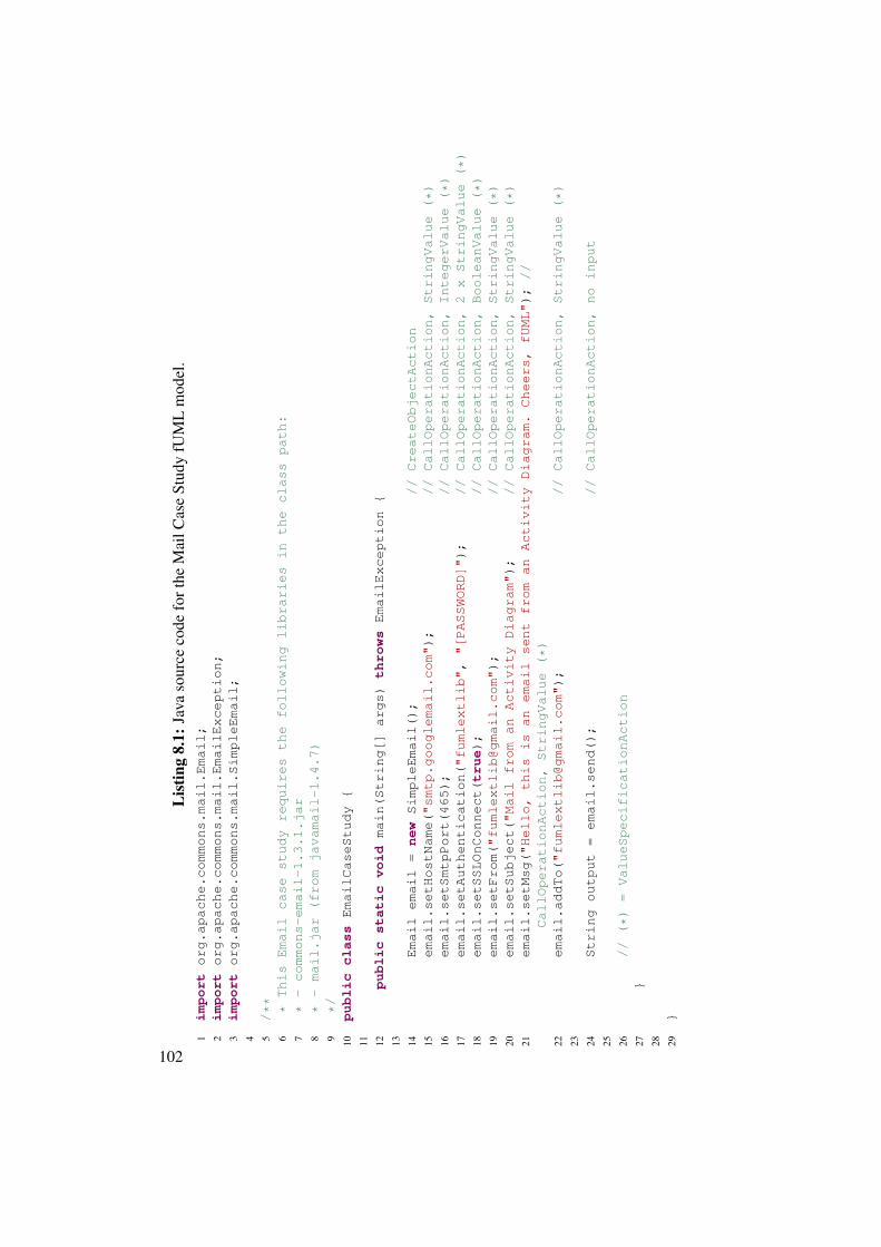
Lis
ting
8.1:
Java
sour
ceco
defo
rthe
Mai
lCas
eSt
udy
fUM
Lm
odel
.1
importorg.apache.commons.mail.Email;
2importorg.apache.commons.mail.EmailException;
3importorg.apache.commons.mail.SimpleEmail;
4 5/**
6*ThisEmailcasestudyrequiresthefollowinglibrariesintheclasspath:
7*-commons-email-1.3.1.jar
8*-mail.jar(fromjavamail-1.4.7)
9*/
10publicclassEmailCaseStudy{
11 12publicstaticvoid
main(String[]args)
throwsEmailException{
13 14Emailemail=
new
SimpleEmail();
//CreateObjectAction
15email.setHostName("smtp.googlemail.com");
//CallOperationAction,StringValue(*)
16email.setSmtpPort(465);
//CallOperationAction,IntegerValue(*)
17email.setAuthentication("fumlextlib","[PASSWORD]");
//CallOperationAction,2xStringValue(*)
18email.setSSLOnConnect(true);
//CallOperationAction,BooleanValue(*)
19email.setFrom("[email protected]");
//CallOperationAction,StringValue(*)
20email.setSubject("MailfromanActivityDiagram");
//CallOperationAction,StringValue(*)
21email.setMsg("Hello,thisisanemailsentfromanActivityDiagram.Cheers,fUML");//
CallOperationAction,StringValue(*)
22email.addTo("[email protected]");
//CallOperationAction,StringValue(*)
23 24Stringoutput=email.send();
//CallOperationAction,noinput
25 26//(*)=ValueSpecificationAction
27}
28 29}
102

Figure 8.1: Mail Case Study UML activity depicted in the Eclipse UML2Tool Editor.
103

Figure 8.2: Mail Case Study UML activity depicted as an UML activity diagram.
Figure 8.3: E-mail sent by executing the Mail Case Study - a view into the receiver’s GoogleMail inbox.
104

Evaluation
• Usability. The usability of the Integration Layer prototype in form of the UML2PreparerUI and the Eclipse fUML External Library Plugin itself is straight forward to evaluate.Furthermore, the usage of the Eclipse Jar2UML plugin, that generates the UML classmodel representing the structure of the reverse engineered Apache Mail library JAR file,turned out to be a procedure requiring only a small amount of steps all performed usinga dialog wizard. Moreover, it takes only a small timely effort (when compared with theoverall modeling effort) for the modeler to use the UML2Preparer UI to prepare a givenUML class model, representing the structure of the Apache Commons Email library, andsetting up an Eclipse run configuration for the fUML External Library Eclipse Plugin.Creating a UML activity model that itself is able to do the same job without using any ex-ternal library is out of the scope of this work and can be assumed to involve a much highereffort. Doing so would require to model the logic used within the Apache Commons Emaillibrary and the JavaMail API from scratch.
• Correctness. Regarding the correctness, executing both the constructed Java applicationand the corresponding UML activity model produces the same result. In other words,the composed e-mail is correctly sent as depicted by the receiver’s Google Mail inbox inFigure 8.3. This means that the interceptions made by the Integration Layer prototypeare perform as expected. In more detail, the CreateObjectAction successfully createdan instance of the SimpleEmail class defined in the Apache Commons Email library.Moreover, all defined preceding CallOperationActions that call operations defined in theApache library are carried out as expected (i.e., they correctly call operations upon theSimpleEmail target object passing the specified parameter values). The integrationtest that executs the Mail Case Study evaluated the String output value produced by theUML activity to be as expected. Consequently, the correctness of the developed prototypefor this case study, when evaluated on achieving the expected result, is confirmed.
• Performance. On one hand, performing the execution of the plain Java implementation,as depicted in Listing 8.1, takes approximately 6.5 seconds. This includes the make, com-pile, and run process. The run process alone takes about 4.25 seconds. On the other hand,executing the UML activity model visualized in Figure 8.1 also consumes approximately4.5 seconds. One might not expect a rather simple and small Java application like thisto take as much time but it turns out that most of the execution time is consumed by theemail.send() statement in line 24 of Listing 8.1. In summary, during the execution ofthis statement, the Apache Commons Email library creates a Secure Sockets Layer con-nection to the specified SMTP server, authenticates itself using the provided credentials,and transmits the specified e-mail message. Additionally, the execution time of both theplain Java application and the corresponding UML activity model depend on the currentconnectivity between the client (i.e., the computer executing the case study application)and the server (i.e., the Google Mail server handling the incoming requests).
The Mail Case Study can be concluded as proving the Integration Layer prototype to bestraight forward to use, the activity itself to be interpreted as expected, and the performance of
105

both the plain Java application and the UML activity model to be almost identical.
8.4 Petstore Case Study
The Petstore Case Study uses the same external library and operation calls as used in the MailCase Study (see Chapter 8.3) but rather than building a UML activity model that is equivalent toa plain Java application, a different approach is taken. The basic idea behind the Petstore CaseStudy is to extend both an existing plain Java application and an existing UML activity model toprovide additional functionality. Hence, the ability of the prototype to handle the execution ofan existing application that has been extended with the usage of an external library is taken intoconsideration.
The Java version of the application4 has been developed by Antonio Goncalves having inmind the original Java Petstore application that has been built in order to depict the functional-ities of J2EE (and later Java EE) to develop e-commerce web applications. The correspondingUML model has been developed by hand and represents part of the functionality of the JavaPetstore application.
The extension made to the Petstore Java application has been realized as a service classcalled MailService. In brief, the latter class contains a method that takes an Order objectas input and retrieves the associated Customer object from it to use his or her e-mail addressas recipient for sending a confirmation e-mail message. In the UML model, one activity called“MailService” takes an e-mail address as input and uses it to compose an e-mail and send it to thedesignated recipient. While Figure 8.4 depicts a part of the UML model, Figure 8.5 visualizes the“SendEmail” activity from the same model in form of a diagram. The e-mail address providedas input for the “MailService” CallBehaviorAction is initially read from a “Customer” object viaa ReadStructuralFeatureAction. The Customer itself originated from the “scenario7Customer”CallBehaviorAction execution. The “MailService” activity is largely equivalent to “MailAc-tivity” depicted in Figure 8.2 except that it additionally takes the customer’s e-mail address asinput. More specifically, the customer’s e-mail address is used as input parameter for the “Ad-dToCallOperationAction”.
The “scenario7Customer” CallBehaviorAction itself calls the “scenario7” activity and readsthe Customer object from its output (cf. Figure 8.4). The output produced by the “scenario7”activity is an “Order” object resulting from executing the “confirmOrder()” CallOperationAc-tion calling the “confirmOrder(sessionId : Integer)” operation from the ApplicationControllerclass. The input objects required for making the latter operation call are established by callingthe “scenario6” activity via a CallBehaviorAction. In brief, the “scenario6” activity representsthe actual scenario establishing customers, items, and services used in this case study.
4The source code for Antonio Goncalves’s Java Petstore application has been retrieved from https://github.com/agoncal/agoncal-application-petstore-ee6.
106

Listing 8.2: Java source code of the Petstore Case Study.1 package org.agoncal.application.petstore;2
3 @RunWith(Arquillian.class)4 public class SendEmailIT extends AbstractServiceIT {5
6 @Inject7 private OrderService orderService;8 @Inject9 private CustomerService customerService;
10 @Inject11 private CatalogService catalogService;12 @Inject13 private MailService mailService;14
15 @Test16 public void sendEmailTest() {17
18 // Creates objects19 Address address = new Address("78 Gnu Rd", "Texas", "666", "WWW");20 Customer customer = new Customer("Lisa", "Appleseed", "liz", "liz", "
[email protected]", address);21 CreditCard creditCard = new CreditCard("1234", CreditCardType.
MASTER_CARD, "10/12");22 List<CartItem> cartItems = new ArrayList<CartItem>();23
24 // Adds items to cart items list25 CartItem cartItem1 = new CartItem(catalogService.searchItems("Bulldog
").get(0), 1);26 CartItem cartItem2 = new CartItem(catalogService.searchItems("Poodle"
).get(0), 1);27 cartItems.add(cartItem1);28 cartItems.add(cartItem2);29
30 // Creates order31 Order order = orderService.createOrder(customer, creditCard,
cartItems);32
33 // Sends confirmation email34 mailService.sendConfirmationEmail(order);35
36 }37
38 }
107

Figure 8.4: Petstore Case Study UML activity depicted in the Eclipse UML2Tool Editor.
108

6HQG(PDLO
scenario7Customer
customer
read email
object result
MailService
email outputParameter
sendConfirmation� String
sendConfirmation�
[true]
Figure 8.5: Petstore Case Study UML activity depicted as UML activity diagram.
Figure 8.6: E-mail sent by executing the Petstore Case Study - a view into the receiver’s GoogleMail inbox.
109

Evaluation
• Usability. Within this case study, when compared with the other performed case studies,the UML model is not constructed from scratch but rather builds on top of an existingmodel. To be more precise, the existing UML model contains both UML classes andUML activities. Basically, that model represents part of the logic of the Java Petstoreapplication developed by Antonio Goncalves. Yet, it is not a complete representation ofits Java counterpart. For example, it does not use a database nor does it require any servletcontainer. In order to execute the activities of to the UML model, a certain customizationhas to be made. Intially, in order to execute the activities already existing in the UMLmodel (i.e., before any extension to it has been made) need to be modified. This necessityof this modification solely lies in the fact that certain OpaqueBehaviors have not beenmodeled and therefore need to be replaced by PrimitiveBehaviors in order to correctlyexecute the model. However, this replacement step is done by the Integration Layer andthe modeler does not have to be aware of it.
• Correctness. When comparing the results of both executing the UML activity createdby extending the existing UML model and the JUnit test created for Goncalves’s Petstoreapplication, they both lead to the same result as visualized by the Google Mail inbox inFigure 8.6. On one hand, the extension made to Goncalves’s Petstore application is repre-sented by the added MailService and SendEmailIT (see Listing 8.25) test class. Onthe other hand, the UML model has been extended by three additional activities, namely“scenario7Customer”, “SendEmail”, and “MailService”.
• Performance. Looking to it performance wise, executing the SendEmail activity takesapproximately 6 seconds when done using the temporarily modified Eclipse fUML Ex-ternal Library Plugin6. On the other hand, running the created SendEmailIT test, thathas been added to Goncalves’s Petstore implementation, the amount of time consumed tofinish the execution equals to approximately 27 seconds from which approximately 4.5seconds is consumed by the actual test run. Most of the execution time is consumed bystarting up the GlassFish servlet container and related services.
In conclusion, the usability of the Integration Layer prototype, in form of the Eclipse fUMLExternal Library Plugin, is equal to the case study in Chapter 8.3. Hence, it is straight forward touse. The correctness, when measured on the produced outcome of both alternatives, is provided.Furthermore, the performance differs by approximately 1.5 seconds even if the startup time ofthe servlet container required to execute Goncalves’s Petstore implementation is not taken intoaccount. A hypothesis explaining this difference is that, even both the fUML activity and theplain Java project produce the same outcome, they are not equivalent and hence their executiontime differs. In order to establish a more reliable performance evaluation of the fUML virtualmachine together with the Integration Layer prototype, more sophisticated (i.e., more complexand larger) case studies need to be constructed and executed.
5Note that asserts and imports in Listing 8.2 are removed due to space limitations.6Note that the performance measured takes into account the temporary modification made to the Eclipse fUML
External Library Plugin replacing existing OpaqueBehaviors within the model before the actual execution proceeds.
110

8.5 Database Case Study
The Database Case Study aims to evaluate the usage of an external library that requires morecomplex library calls such as calling operations by passing a non-primitive parameter value. Theexternal library used within this case study, is an open-source document database called mon-goDB7.
Listing 8.3 shows the Java implementation of the case study. Initially, a MongoClientobject is created for connecting to the database server running on the local machine. Next, aspecific database and table within it are retrieved from the database server. Furthermore, a newBasicDBObject object is created and some exemplary key-value pair is put into it. Line 19concludes the insertion process by inserting the created document into the retrieved database ta-ble. The query process begins with creating another BasicDBObject object used to query thedatabase table on a specific key-value pair. Line 24 executes the query and returns a DBCursorobject that can be used to iterate over the result set. Line 26 shows how to retrieve the firstDBObject from the result set.
Figure 8.8 shows the constructed UML activity, namely “DatabaseActivity”, depicted withinthe Eclipse UML2Tools Editor. Figure 8.7 visualizes the same model in form of a UML activitydiagram. In order to ensure the same execution flow as depicted in Listing 8.3, control flowsare required. First, the connection to the local database is established and the desired table isretrieved (Line 11 to 14 in Listing 8.3 and from the initial control flow to “GetCollection” Cal-lOperationAction in Figure 8.7). Next, a new document with the specified values is created andinserted into the database table (Line 17 to 19 in Listing 8.3 and from the “document” nodeto the “Put” and “Insert” CallOperationActions in Figure 8.7). Then, a new query, looking forthe same document as specified in the insertion procedure, is created and passed to the findmethod defined in the com.mongodb.DBCollection class (Line 22 to 24 in Listing 8.3and from the “query” node to the “Put” and “Find” CallOperationActions in Figure 8.7). Fi-nally, DBObject instances are retrieved by iterating over the DBCursor object (Line 26 inListing 8.3 and from the “Next” CallOperationAction to the “OutputDbObject” ActivityParam-eterNode in Figure 8.7).
7The external library JAR file mongo-java-driver-2.10.1.jar representing the mongoDB has beenretrieved from http://www.mongodb.org/.
111

Figure 8.7: Database Case Study UML activity depicted as an UML activity diagram.
112

Listing 8.3: Java source code for the Database Case Study.1 package sandbox;2
3 import com.mongodb.*;4
5 import java.net.UnknownHostException;6
7 public class DatabaseCaseStudy {8
9 public static void main(String[] args) throws UnknownHostException {10
11 MongoClient dbClient = new MongoClient();12
13 DB database = dbClient.getDB("mydatabase");14 DBCollection table = database.getCollection("mytable");15
16 // Insert data17 BasicDBObject document = new BasicDBObject();18 document.put("mykey", "myvalue");19 table.insert(document);20
21 // Search data22 BasicDBObject query = new BasicDBObject();23 query.put("mykey", "myvalue");24 DBCursor cursor = table.find(query);25
26 DBObject resultObject = cursor.next();27
28 }29
30 }
113

Listing 8.4: The put method definition of the org.bson.BasicBSONObject class.1 package org.bson;2
3 // import ...4
5 public class BasicBSONObject extends LinkedHashMap<String,Object> implementsBSONObject {
6
7 // ...8
9 /** Add a key/value pair to this object10 * @param key the field name11 * @param val the field value12 * @return the <code>val</code> parameter13 */14 public Object put( String key , Object val ){15 return super.put( key , val );16 }17
18 // ...19
20 }
Listing 8.5: The insert method definition of the com.mongodb.DBCollection class.1 package com.mongodb;2
3 // import ...4
5 public abstract class DBCollection {6
7 // ...8
9 /**10 * Saves document(s) to the database.11 * if doc doesn’t have an _id, one will be added12 * you can get the _id that was added from doc after the insert13 *14 * @param arr array of documents to save15 * @return16 * @throws MongoException17 * @dochub insert18 */19 public WriteResult insert(DBObject ... arr){20 return insert( arr , getWriteConcern() );21 }22
23 // ...24
25 }
114

Figure 8.8: Database Case Study UML activity depicted in the Eclipse UML2Tool Editor.
115

Evaluation
When analyzing Listing 8.3 in more detail and with special attention on the operation inputparameters one can identify that not only primitive values are passed but also single complexvalues (see line 19 and 24). Moreover, the put method in BasicBSONObject is definedas depicted in Listing 8.4. Even if primitive parameters (i.e., the two Strings “mykey” and“myvalue”) are passed for both input parameters, the Integration Layer prototype does notproperly handle the operation call.
Therefore, the Integration Layer prototype fails to correctly execute this case study. First, itfails because a mix of primitive and complex parameters is not supported as described in Sec-tion 7.5. Before the case study has been conducted it was not clear if the case study requiresfunctionality that is not supported by the Integration Layer prototype. Secondly, even if the pro-totype would support a mix of primitive and complex parameters on operation calls, it wouldexpect an instance of a plain Java Object to be passed as the second parameter of the putoperation (see line 14 of Listing 8.4) instead of a String as depicted in line 18 and 23 of List-ing 8.3. Listing 8.5 shows the definition of the insert method of the DBCollection classon which one can identify two scenarios not yet taken into account in the prototype implementa-tion. First, the prototype expects an array of DBObject even if only one object is passed8. Andsecondly, a similar issue is encountered as mentioned in association with the “put” method.Namely, a “BasicDBObject” is passed instead of the expected “DBObject”. Moreover, theexpected object is in fact an interface and thus cannot be instantiated.
As a result of the fact that the UML activity does not successfully produce the expected resultbecause of missing support for more complex scenarios, it produces a non correct outcome andhence the performance cannot be safely determined. When looking on the usability, the artifacts(i.e., the UML class model and the UML activity model) produced for this case study are used inthe same way as in the other case studies. Namely, the UML2Preparer UI and the Eclipse fUMLExternal Library Plugin are used. Again, both of them are straight forward to use. On the otherhand, for the Integration Layer prototype to be able to successfully handle the execution of thedefined UML activity (and hence provide correctness and enable the performance evaluation),at least the following scenarios or use cases have to be supported by the Integration Layer:
• Interface input parameters. CallOperationActions specifying complex value parametersthat implement an interface defined in the external library should be supported.
• Mixture of primitive and complex input parameters. Passing of both complex andprimitive value input parameters in CallOperationActions should be supported. This alsoincludes passing arrays as input parameters.
To summarize, the Integration Layer prototype is able to execute the UML activity definedin this case study only up to the point when the “Put” CallOperationAction is reached. Hence,the database connection is successfully created as can be seen in the database server log, but anyexecution beyond that point is suspect to failure due to unsupported scenarios.
8Note that within the standard Java language it is sufficient to pass a single object for any “...” notation.
116

8.6 Lessons Learned
To summarize, three case studies have been performed during the evaluation phase of this work.The research questions on which the Integration Layer prototype has been evaluated duringthe execution of these case studies include the usability, correctness, and performance of thedeveloped prototype. While evaluating the usability, the additional effort required to use externallibraries by using the developed prototype, has been taken into account. The correctness has beenevaluated by comparing both the execution outcome of the plain Java counterpart and the fUMLactivity model and by highlighting unsupported scenarios. The performance has been evaluatedbased on the execution time required to generate any outcome and finish the execution.
When looking on the usability of the prototype during the execution of the case studies wecan conclude that the overall modeling process has not been affected. In case the modeler intendsto build a model that accesses classes or operations from external libraries, the external libraryfirst needs to be reverse engineered in order to gain its structure (i.e., in form of a UML classmodel) and second, it needs to be prepared (i.e., by using the UML2Preparer) in order to be usedby the prototype.
Moreover, when taking into account that missing support for specific use cases might affectthe correctness of the outcome produced during the fUML activity execution we mentioned thatthe Database Case Study represents such an example. In more detail, the Database Case Studycould not be correctly executed because the Integration Layer prototype does not support a mixof primitive and complex parameters as operation input parameters. Additionally, passing theinstance of a specialization of a Java class (e.g., an instance of the Java String class as aspecialization of the Java Object class) as an operation input parameter, also represents anunsupported use case. Both the Mail and Petstore Case Study produced the expected outcomeand hence is evaluated to be correct.
Furthermore, on one hand by evaluating the performance of both the Mail Case Study andthe Petstore Case Study by comparing the Java counterpart with the fUML activity we could notidentify a significant difference (0̃.25 seconds of difference). On the other hand, when compar-ing the execution time for the Petstore Case Study, even when dismissing the startup time forthe services required in Goncalves’s petstore application, the time differs by about 1.5 seconds(6̃ versus 4̃.5 seconds). In order to evaluate the hypothesis, which states that the difference iscaused by the non-equivalent implementations, a larger and equivalent case study needs to beperformed.
While performing the case studies we encountered several use cases or scenarios not thoughtof when implementing the Integration Layer prototype. For some of these unsupported use cases,the developed prototype has been extended (also consider Section 7.4). They are discussed inthe following:
• External libraries that themselves depend on libraries. At the time the first case study,namely the Mail Case Study, has been developed, the need for more than one Java libraryarose. In more detail, the Apache Commons Email library used within the scope of theMail and Petstore Case Studies depends on the JavaMail API. In order to support addi-
117

tional libraries, the DynamicClassLoader needed to be extended in order to be able to loadclasses and operations from multiple dependent JAR files.
• Single complex input parameter. While constructing the Database Case Study, supportfor CallOperationActions defining a single complex input parameter has been added. Tobe more precise, while implementing the plain Java application we recognized the needfor an object input parameter.
Moreover, while performing the Database Case Study, we learned that a set of other usecases need to be supported in order to achieve an execution that produces the desired outcome.Those use cases include the support for CallOperationActions specifying complex input valueparameters that implement an interface defined in the external library and the mixture of primi-tive and complex input parameters. While adding support for these use cases might produce thedesired outcome when running the Database Case Study, the implemented use cases will alsoincrease the set of capabilities of the prototype. As a next step, to further advance the proto-type capabilities, an in-depth investigation on the most common library use cases and how thesecould be implemented by the Integration Layer, is suggested. The resulting list of most frequentuse cases could then be used to gradually increase the Integration Layer capabilities by imple-menting their support. It is open to the investigation outcome to what extend those additionallydiscovered prototype limitations can be eliminated.
8.7 Threats to Validity
There are several threats to validity [37] encountered that might have affected the performedstudies.
• Construct validity. The construct validity concerns to what extent the operational mea-sures that are studied represent what the researcher has in mind and what is investigatedaccording to the research questions. The research questions raised in Section 8.1 mightbe interpreted differently by the researcher and the reader of this work. For example, theusability examined takes into account how much the modeling process is affected by theprototype but does not take into account the end user experience.
• Internal validity. Threats to internal validity arise primarily from our technique for veri-fying correctness. For instance, we evaluated that a study is correctly supported based onits produced outcome but we did not further examined the process involved in constructingthe outcome. Hence, objects built by the Integration Layer prototype during the executionmight differ from what is expected or valid by the fUML standard.
• External validity. External validity concerns the generalization of the case study results.The case studies that we built capture the functionality of the Integration Layer prototypebut they might not scale up to real world scenarios.
118

CHAPTER 9Related Work
State of the art that has to be considered for this thesis concerns how external libraries may beinvoked when executing fUML models. The different, currently available approaches on how touse external libraries in MDE are also relevant for this work.
9.1 Approaches Taken by Other fUML Compliant Tools
First of all, there are a number of tools available to execute UML models. A rather large partof them is not conform with the fUML standard. In this section we limit the description ofrelated approaches to those tools that comply with the fUML standard. Currently there existthe following tools1, frameworks, and approaches that allow to execute UML models compliantwith the fUML standard:
• fUML Reference Implementation. The fUML reference implementation is availableunder the Common Public License (CPL) version 1.0 and has originally been developedon behalf of the Lockheed Martin Corporation2 by Model Driven Solutions, a spin-offof Data Access Technologies, Inc. The reference implementation can, for example, beused to evaluate the fUML conformance of vendor specific implementations. The fUMLFoundational Model Library is part of the fUML standard definition by the OMG [33]and also implemented in the fUML reference implementation. Therefore, this libraryimplementation conforms to the fUML standard and currently contains primitive functionsfor primitive data types. The ability to extend this library is given but comes with thedownside of rewriting source code for every single library function. A more detaileddiscussion is provided in Section 9.2.
1The list of existing tools to execute UML models compliant with the fUML standard has been taken fromhttp://modeling-languages.com/list-of-executable-uml-tools/ on December 6, 2013.
2The Lockheed Martin Corporation is an American global aerospace, defense, security, and advanced technologypublic company.
119

• Cameo Simulation Toolkit. NoMagic, Inc.3 has developed an add-on for their commer-cially distributed MagicDraw software called the Cameo Simulation Toolkit. MagicDrawis a multi-purpose visual modeling tool including team collaboration support. It allows tocreate UML, SysML, BPMN, and UPDM models and is designed for software analysts,business analysts, programmers, and QA engineers basically facilitating the analysis anddesign of object oriented systems and databases. The Cameo Simulation Toolkit add-on,on the other hand, claims to be the first in the industry extendable model execution frame-work based on OMG fUML and W3C SCXML standards allowing to model UML 2 statemachine and activity models4. Using the toolkit it is possible to access external librariesif the associated JAR files have been previously added to the CLASSPATH variable of theappropriate properties file5. Next, for example as depicted in Figure 9.1, the “body” at-tribute of an OpaqueAction can be used to specify a call to an external library operation6.Figure 9.2 shows the result of executing the latter example.
Figure 9.1: NoMagic MagicDraw Cameo Simulation Toolkit external library call specification.
• LieberLieber AM|USE. LieberLieber Software GmbH is a privately held Austrian soft-ware engineering company with a model engineering division that builds several Enter-
3NoMagic, Inc. is a privately held company operating in Europe, Thailand and headquartered in the USA.MagicDraw represents their flagship product.
4Information regarding the Cameo Simulation Toolkit has been retrieved from the NoMagic company websiteat http://www.nomagic.com/products/magicdraw-addons/cameo-simulation-toolkit.html on December 6, 2013.
5In the Mac OS X version of the MagicDraw software, the CLASSPATH variable to be modified is located in the“mduml.properties” or “csm.properties” file in case of the Cameo Systems Modeler.
6The mentioned approach to access external library resources using the Cameo Simulation Toolkit has beenproposed by the NoMagic customer support and has not been further evaluated.
120

Figure 9.2: NoMagic MagicDraw Cameo Simulation Toolkit external library call specificationexecution result.
prise Architect7 add-ons and plugins. The AM|USE add-on can be used to execute behav-ior models (i.e., state machines and activities) within Enterprise Architect. Their approachinitially generates Microsoft .NET code from UML models, then compiles and executesthe generated code8. Hence, the obtained .NET code could potentially be extended withexternal library calls and executed in a runtime environment outside the Enterprise Ar-chitect software. There exists a functionality9 that allows to reference external DLL filesfrom which classes can be instantiated.
• Eclipse Alf Implementation10. Alf is the shorthand for Action Language for fUML andrepresents a textual language with Java-like syntax. Alf has, like fUML, been standardizedby the Object Management Group. Its main goal is to act as the surface notation for spec-ifying executable UML behaviors within an extensive model that is primarily representedusing the usual graphical notations of UML [35]. In other words it tries to overcome theissues raised by too detailed graphical models. A typical example might include the mod-eling of operations of classes that would otherwise quickly grow a graphical model into
7Enterprise Architect, developed by Sparx Systems, is a proprietary visual modeling and design tool based on avariety of standards. These include UML, SysML, BPMN, BPEL, SoaML and so forth.
8Information regarding the capabilities of the AM|USE add-on have been taken from the LieberLieber websiteat http://www.lieberlieber.com/en/model-engineering/AMUSE/product-overview/. Ac-cessed December 2013.
9The functionality that allows to reference external DLL files is called “add reference to external .net library”.10The Eclipse Alf implementation is available online at https://code.google.com/p/e-alf/. Ac-
cessed January 2014.
121

a cumbersome and, for a human, incomprehensible size. The developers of the EclipseAlf implementation did not consider the support for external libraries or other Java code intheir implementation. Hypothetically, one way to extend the capabilities of the Eclipse Alfimplementation is to re-implement the functionalities provided by existing Java librariesin form of Alf code with similar drawbacks as the approach of extending the fUML Foun-dational Model Library.
• Papyrus UML. Papyrus is an open source Eclipse plugin that allows UML 2 modelingin a graphical way. Within the currently available version of the Eclipse Papyrus plugin,UML models cannot yet be executed as it still represents (only) a graphical modelingtool. However, in the Papyrus project, current work is targeted at building an extensibleframework for model execution and debugging called Moka 11. Part of this work is the de-velopment of an execution environment for fUML models conform to the fUML standard.When modeling UML models within the Papyrus editor, it is possible to load externalresources (i.e., already defined UML models) and reference them, for example, in UMLactivity model elements. In more detail, the latter referencing procedure within Papyrusis similar to the one in the Eclipse UML2 Tools editor. On the other hand, when lookingfor ALF support in Papyrus, standard ALF libraries and fUML libraries can be used [7].Therefore, when specifying fUML libraries through the Foundational Model Library12,functionalities already provided by powerful Java libraries have to be re-implemented inthe appropriate form and added to the fUML Foundational Model Library.
• Pópulo. The Pópulo tool presented by Fuentes et al. [10] is fully compliant to UML 2.0and can execute and debug UML models that are specified using the fUML action lan-guage. In other words, it is able to execute and debug activity diagrams containing ac-tions. They try to overcome tool-interoperability and extensibility problems by providingcustomization capabilities. By using UML profiles, the supported action language can beextended. The execution semantics of the introduced stereotypes, has to be defined usinga GPL such as Java. The resulting drawbacks are therefore the same as those from theapproach of extending the fUML Foundational Model Library.
• Gessenharter et al. Yet another approach of model execution is to generate code outof UML models. Gessenharter and Rauscher present in [11] a prototype that is able togenerate code out of UML 2 activity diagrams. In this case, whenever an operation iscalled at runtime, its specified behavior is executed. Hence, a code fragment of any lan-guage can be executed. As a consequence of that, also external Java source code can beexecuted. The presented approach generates Java code for activities preceded by modeltransformations. In order to specify behavior, UML activities are used that directly containactions. To fit the specification when modeling actions, set, get, add, and remove methods
11The bug ticket named “Bug 405389 - [Moka] Papyrus shall provide a generic and extendible frameworkfor execution and debugging of models” concerning the development of Moka is available online at https://bugs.eclipse.org/bugs/show_bug.cgi?id=405389. Furthermore, the source code associated with theMoka project can be found online at https://eclipse.googlesource.com/papyrus/org.eclipse.papyrus/+/0.10_RC1/sandbox/Moka/. Accessed January, 2014.
12The Foundational Model Library is presented in chapter 9 of [31].
122

are mapped to StructuralFeatureActions and LinkActions. Moreover, when an action witha corresponding attribute is executed, the mapped StructuralFeatureAction or LinkActionis called. Furthermore, their approach translates sequences of actions into sequences ofmethod calls in which each method represents the implementation of its correspondingaction. Additionally, those sequences are implemented as dedicated threads since theymight be executed concurrently. Overall, when compared with fUML, their approach isnot interpreter-based as it uses the technique of code generation.
9.2 The fUML Foundational Model Library and SimilarApproaches
The only way to use external libraries that conforms to the fUML standard is to extend the fUMLFoundational Model Library, that already provides primitive functions for primitive data types,as foreseen in the fUML standard [31]. The downside of this approach is that it requires writingsource code for every single function of a library to make it available to the modeler. A rather un-reasonable amount of work would be required to cover the huge set of existing libraries. In moredetail, in order to do so, the fUML.Semantics.CommonBehaviors.BasicBehaviors.OpaqueBehaviorExecution class residing in the fUML reference implementation canbe overwritten and the doBody method, taking input- and output-parameters, implemented.
Thus, as an example, the org.modeldriven.fuml.library.stringfunctions.StringConcatFunctionBehaviorExecution class represents such a library func-tion. Namely, it represents a re-implementation of the functionality provided by the java.lang.String.concat operation. Moreover, one instance of such a class needs to be regis-tered at the ExecutionFactory as it is done, for example, in the fUML.Library.PrimitiveBehaviors.addPrimitiveBehavior operation.
Our approach, on the other hand, allows to import any Java library without producing anysource code or requiring detailed knowledge of the fUML virtual machine.
Another approach could be specifying the functionality of libraries by fUML models result-ing in a library of fUML models providing the same functionality as the external Java librarywhich shall be used in the model. Those fUML library models could then be natively invokedby any other fUML model whenever necessary. But again the specification of fUML modelsproviding the same functionality as existing libraries requires an extensive amount of effort.Furthermore, this approach is only applicable in combination with extending the fUML Founda-tional Model Library, as some primitive functionalities, as for instance accessing the file system,are not yet available.
9.3 Other Approaches
Generally, there exists a set of other approaches for accessing advanced and complex libraryfunctionality that are not fUML compliant. Some of them are mentioned below.
123

Kirshin et al. describe in [17] a generic model execution engine that enables the simulationof models. In this approach, developed in the IBM Haifa Research Lab, Java is used as actionlanguage enabling to call any Java library by executing source code, stored for each model el-ement (e.g., Action elements), whenever the model is interpreted. Many UML execution toolsuse this approach. The main difference between this approach and ours is that we do not storesource code behind model elements but rather use special place holder activities that triggercalls to the actual library at runtime through a dedicated Integration Layer that uses fUML ex-tensions providing a command API and an event mechanism. The approach of Kirshin et al. hasbeen realized as an extension to the commercially distributed IBM Rational Software ArchitectSimulation Toolkit13. The latter extension adds execution and simulation capabilities to IBM’sRational Software Architect.
Furthermore, the UML Model Simulator developed on top of the Rational Software Archi-tect by Kirshin et al., supports step-wise execution and run to break-point execution. Its firstversion supports UML classes and primitive data types and the execution of activities. Addition-ally, by applying stereotypes to UML elements, their behavior can be changed. In more detail, aUML profile has been developed for model simulation. Among others, it can be used to specifyelements containing Java code and an external classpath to link them with existing Java code.Their prototype contains a visualization technique that highlights different execution states byassigning different colors to UML elements. Figure 9.3 shows a UML behavior model depictedin the diagram visualization tool that is part of their prototype. A magenta node represents anode providing a token, a blue node shows which edges are passed by a token, and a green nodehighlights a node that is ready for execution.
13The IBM Rational Software Architect Simulation Toolkit is available online at http://www-03.ibm.com/software/products/en/ratisoftarchsimutool/. Accessed January 2014.
124

Rational Software Architect (RSA)
Eclipse platform
UML Model Simulator
Generic model execution engine
UML Activities
UML State Machines
Voice Applications Profile
. . .
Extensions:
Figure 6: UML Simulator
The first version of the tool supports UML classes and primitive data types, and focuses on the execution of activities. It also supports Java as an action language. The behaviour of a UML element can be changed using profiles by applying stereotypes to UML elements. The tool can be extended to support the execution of models that conform to a specific profile.
The UML Model Simulator provides a wide range of capabilities. It supports the most commonly used execution modes such as step-wise execution and run to break-point. It allows run-time state observation, including the visualization of the current execution state, token offers, and parameter values. The debugger also allows dynamic object creation and user initiated invocation of behaviours and operations. The most useful feature is the visualization of the execution of model behaviour.
We extended RSA with a Model Debugging perspective that contains various views:
Model Explorer view. This is the corresponding RSA view with the addition of two items to the popup-menu: Debug Model used to start a model simulation session, and Add Breakpoint, which can be applied to any runnable element of the model.
Debug view. This view is responsible for the control of the execution process (starting, stopping, and step mode execution), object creation and destruction, observing the values of objects’ attributes, and invoking the operations on the objects.
Figure 7: Debug View
Call Stack view. This view shows all running behaviours organized according to the call history.
Figure 8: Call Stack View
I/O view. This view, is used to observe outputs sent from the model and to send or broadcast signals to model behaviours.
Figure 9: I/O View
Ready view. This view shows all elements that are ready for execution and all elements that have reached breakpoints. The user can select the next element for execution.
Figure 10: Ready View
Breakpoints view. This view lists all active breakpoints.
Diagram visualization. This is the most powerful part of the tool. It illustrates the execution of a UML behaviour model. The user can see which nodes are ready for execution (green), which edges pass tokens (blue), and which node provides the token (magenta):
Figure 11: Diagram Visualization
We developed a UML profile for model simulation. The profile is used to specify:
Elements containing Java code (Java as an action language)
External classpath for linking with existing code
Figure 9.3: UML behavior model execution depicted in the diagram visualization tool of theprototype of Kirshin et al. [17].
125


CHAPTER 10Conclusion
This chapter summarizes the work completed within this thesis and outlines possible futurework.
10.1 Summary
On one hand, re-using software components improves quality and increases productivity [15]and on the other hand, Hutchinson et al. report in [14], that the usage of MDE enables report-edly productivity increases up to 800 percent. Within MDE, UML is the most used modelinglanguage. When UML is used as an executable language, important problems arise. Namely,the semantics of UML is neither precisely nor completely specified. France et al. suggest in [9]that appropriate aspects of modeling languages must be formalized. The fUML standard, de-fined by the OMG, intends to equip the UML standard with formal execution semantics. Morespecifically, it defines precise execution semantics for a subset of UML. In this work, we iden-tified that the fUML standard does not offer a standardized procedure to re-use existing Javalibraries. It rather takes the approach of a Foundational Model Library, which represents a li-brary of user-level model elements that can be referenced in fUML models. At this point intime, with the specification of the fUML standard version 1.1 from August 2013, the Founda-tional Model Library contains the packages PrimitiveTypes, PrimitiveBehaviors, Common, andBasicInputOutput. Therefore, sophisticated functionalities, as provided by, e.g., the Java APIor any third party like Apache libraries, are missing. Hence, building fUML models that buildon top of existing Java libraries is not foreseen in the fUML standard. There are at least twoapproaches to provide the modeler with advanced functionalities in fUML models as they areavailable in today’s Java libraries. On on hand, there is the approach of extending the Foun-dational Model Library by implementing model libraries that basically mimic the functionalityprovided by currently existing Java libraries. But doing so requires an extensive amount of workthat might only be feasible within a community as large as the existing Java open source com-munity. On the other hand, there is our approach that re-uses existing Java libraries such that
127

they can be referenced in the models built by the modeler and are integrated during the modelexecution.
The aim of this thesis was to integrate external Java libraries with the fUML virtual machinesuch that the modeler can benefit from the advanced and complex functionalities provided bythose libraries. Based on the fUML virtual machine developed by Mayerhofer et al. in [20], aprototypical solution has been implemented as main outcome of this work. The implementedprototype can be used to execute fUML models referencing external libraries. To achieve thelatter, the external library initially needs to be made available to the modeler such that it canbe referenced in created models. Next, the model referencing the library needs to be properlyinterpreted such that, for example, library calls are forwarded to the actual library and the resultis integrated into the fUML runtime model.
In order to make the external library available to the modeler, a two-step procedure has beenmade available. First, the external library, either in form of Java source code or as a JAR file, isreverse engineered by either the Eclipse MoDisco tool (in case of Java source code) or by theEclipse Jar2UML tool (in case of a JAR file). Secondly, the UML class model yielded in thefirst step, that represents the external library’s structure, needs to be prepared to be used duringthe model execution achieved by the implemented Integration Layer together with the fUMLvirtual machine. The preparation is required such that the Integration Layer prototype knows,for example, where the JAR file matching the UML class model is located. To realize the latterstep, the UML2Preparer has been built and made available in form of a graphical user interface.The Integration Layer prototype itself has been built in order to be able to detect intended accessto an external library, forward calls to the actual external library, and re-integrate the result ofsuch a call into the fUML runtime model. This also requires the translation of Java objects intofUML objects. The prototype has been made available in form of an Eclipse plugin providing aspecific run configuration dialog.
During the implementation of the Integration Layer prototype, insights have been gainedinto the fUML standard and the fUML virtual machine implementation. These insights havemainly been gained during the execution of three use case studies. The goal was to evaluatethe implemented prototypical solution based on the criteria of usability, correctness, and perfor-mance. The usability evaluation concluded that the overall modeling process is not affected bythe implemented prototype. Furthermore, during the evaluation of the correctness, previouslyunknown limitations of the implemented prototype have been discovered. Moreover, the perfor-mance measurements comparing the time needed for executing both the fUML activity and itsJava counterpart resulted in no significant difference. However, to establish more reliable resultseven larger case studies need to be performed. While some of the limitations encountered by car-rying out the case studies have been taken into account in the prototypical solution of this work,others have been listed as final limitations of the prototype. Limitations that have been takeninto account in the final version of the prototype include the support for libraries that themselvesdepend on libraries. Possible future features that have been listed as final limitations include aset of further fUML actions currently unsupported by the prototype, advanced data structures,
128

and specific use cases of the CallOperationAction and AddStructuralFeatureValueAction.
In this work we also suggest possible extensions that can be made to the Integration Layerprototype to improve its maturity. These include different enhancements and performance im-provements to the existing artifacts. The process of creating a prepared UML class model for alibrary, which can be referenced by fUML activities, could be further simplified from a two-stepprocess into a one-step process. Other enhancements include the elimination of existing limi-tations, such as the support for further fUML actions, advanced data structures, and data types.Furthermore, a study on common library use cases could increase the understanding of featuresdesired most by modelers.
Different approaches on invoking external libraries when execution UML models exist.Mainly, those can be differentiated between being fUML compliant and not being fUML compli-ant. The former includes NoMagic’s commercially available Cameo Simulation Toolkit, Lieber-Lieber’s AM|USE plugin for Sparx System’s proprietary visual modeling and design tool En-terprise Architect, and open source tools such as the Eclipse Papyrus plugin and the Pópulotool. Gessenharter and Rauscher [11] provide a tool that initially generates source code out ofa model and then compiles and executes the generated code. All of the investigated tools uselargely different techniques to access external library functionality or do not intend and provideexternal library access. Expanding the fUML Foundational Model Library, as foreseen in thefUML standard, by providing similar advanced functionalities as provided by existing Java li-braries, represents another interesting approach. The drawback of the latter approach is that itmight require a community as large as the existing Java community in order to implement thevast amount of library functions as they are nowadays available in the Java GPL.
10.2 Future Work
We have completed a prototype version of the Integration Layer and future work might includeto further extend the capabilities of the Integration Layer and improve its maturity. In this respectthe following enhancements and extensions were identified:
• UML2Preparer enhancement. Enhance the capabilities of the reverse engineering pro-cess and the UML2Preparer tool such that it can be done in a one-step process. In detail,the process could look like the following: the modeler choses a JAR library file to be re-verse engineered and prepared and the tool automatically detects dependent libraries andcreates a prepared UML class model out of a selected JAR library file using a reverse en-gineering tool in the background. The detection of dependent libraries could be realizedin a Apache maven-like fashion (i.e., by using the Apache maven dependency detectionmechanism 1) or by using tools like the JarAnalyzer2. Therefore, the process of generating
1An introduction to the Apache maven dependency detection mechanism can be found online at http://maven.apache.org/guides/introduction/introduction-to-dependency-mechanism.html. Accessed January, 2014.
2The JarAnalyzer tool can be found online at http://www.kirkk.com/main/Main/JarAnalyzer.Accessed January, 2014.
129

a prepared UML class model file out of a JAR library file can be boiled down to a one-stepprocess.
• Eliminate existing prototype limitations. Extend the Integration Layer prototype capa-bilities by eliminating the encountered and hence existing limitations. A more detaileddescription on existing limitations can be found in Section 7.5. Removing these limita-tions leads to the following capabilities:
– Support of all fUML actions. The set of fUML actions that are not yet supported bythe Integration Layer (i.e., for example ReadStructuralFeatureAction, ClearStruc-turalFeatureAction, RemoveStructuralFeatureValueAction, CreateLinkAction, Read-LinkAction, DestroyLinkAction, DestroyObjectAction, and ClearAssociationAction)can be implemented to enhance the capabilities and hence extend the supported usecases of the prototype.
– Support of advanced data structures and types. Support for advanced data struc-tures and types like, for example, arrays, enums, and collections as they can be foundin the Java programming language.
– CallOperationAction enhancement. Support for discovered limitations regardingthe CallOperationAction in the Integration Layer. These include the support of mul-tiple complex input parameters, the mixture of primitive and complex input parame-ters, static method calls, and interface input parameters.
– AddStructuralFeatureValueAction enhancement. Adding complex data type sup-port and fUML link creation support to the AddStructuralFeatureValueAction.
• Study on common library use cases. An in-depth investigation on common library usecases in, for example the Java GPL, and how these could be supported and implementedby the Integration Layer could increase the understanding on what kind of IntegrationLayer features are beneficial to the modeler.
• Performance improvements. Increase the Integration Layer’s performance by, for exam-ple, instead of re-translating a Java object into an fUML object every time it is accessed,only re-translate the object when potential changes to it have been made. Sánchez et al.describes in [6] how to keep Java objects in synch with EMF objects.
130

Bibliography
[1] Jim Arlow and Ila Neustadt. UML 2 and the Unified Process: Practical Object-OrientedAnalysis and Design. Pearson Education, 2005.
[2] Daniel G. Bobrow, Richard P. Gabriel, and Jon L. White. Object-oriented programming,chapter CLOS in context: the shape of the design space, pages 29–61. MIT Press, Cam-bridge, MA, USA, 1993.
[3] Marco Brambilla, Jordi Cabot, and Manuel Wimmer. Model-Driven Software Engineeringin Practice. Morgan & Claypool, 2012.
[4] Hugo Bruneliere, Jordi Cabot, Frédéric Jouault, and Frédéric Madiot. Modisco: A genericand extensible framework for model driven reverse engineering. In Proceedings of theIEEE/ACM International Conference on Automated Software Engineering, ASE ’10, pages173–174, New York, NY, USA, 2010. ACM.
[5] Elliot J. Chikofsky and James H. Cross II. Reverse engineering and design recovery: Ataxonomy. IEEE Software, 7(1):13–17, 1990.
[6] Jesús Sánchez Cuadrado, Esther Guerra, and Juan de Lara. The Program Is the Model:Enabling [email protected]. In Software Language Engineering, volume 7745 ofLecture Notes in Computer Science, pages 104–123, 2012.
[7] Arnaud Cuccuru. Papyrus support for Alf. Technical report, Carbot Institut, 2011.Available online at http://www.omg.org/news/meetings/tc/agendas/va/xUML_pdf/Cucurru.pdf.
[8] Krzysztof Czarnecki and Ulrich W. Eisenecker. Generative Programming: Methods, Tools,and Applications. ACM Press/Addison-Wesley Publishing Co., New York, NY, USA,2000.
[9] Robert France and Bernhard Rumpe. Model-driven development of complex software: Aresearch roadmap. In Proceedings of Future of Software Engineering, FOSE ’07, pages37–54, Washington, DC, USA, 2007. IEEE Computer Society.
[10] Lidia Fuentes, Jorge Manrique, and Pablo Sánchez. Pópulo: A Tool for Debugging UMLModels. In Companion of the 30th International Conference on Software Engineering,ICSE Companion ’08, pages 955–956, New York, NY, USA, 2008. ACM.
131

[11] Dominik Gessenharter and Martin Rauscher. Code Generation for UML 2 Activity Dia-grams: Towards a Comprehensive Model-Driven Development Approach. In Proceedingsof the 7th European Conference on Modelling Foundations and Applications, ECMFA ’11,pages 205–220, Berlin, Heidelberg, 2011. Springer-Verlag.
[12] Alan R. Hevner, Salvatore T. March, Jinsoo Park, and Sudha Ram. Design science ininformation systems research. MIS Quarterly, 28(1):75–105, 2004.
[13] Martin Hitz, Gertrude Kappel, Elisabeth Kapsammer, and Werner Retschitzegger. UML @Work. Objektorientierte Modellierung mit UML 2. dpunkt.verlag, 3. edition, 2005.
[14] John Hutchinson, Jon Whittle, Mark Rouncefield, and Steinar Kristoffersen. EmpiricalAssessment of MDE in Industry. In Proceedings of the 33rd International Conference onSoftware Engineering, ICSE ’11, pages 471–480, New York, NY, USA, 2011. ACM.
[15] Suryani Ismail, Wan M.N. Wan-Kadir, Yazid M. Saman, and Siti Z. Mohd-Hashim. Areview on the component evaluation approaches to support software reuse. In InternationalSymposium on Information Technology, volume 4, pages 1–6, 2008.
[16] Frédéric Jouault and Ivan Kurtev. Transforming models with ATL. In Proceedings of theSatellite Events at the MoDELS 2005 Conference, MoDELS’05, pages 128–138, Berlin,Heidelberg, 2005. Springer-Verlag.
[17] Andrei Kirshin, Dolev Dotan, and Alan Hartman. A UML Simulator Based on a GenericModel Execution Engine. In Proceedings of the 2006 International Conference on Mod-els in Software Engineering, MoDELS ’06, pages 324–326, Berlin, Heidelberg, 2006.Springer-Verlag.
[18] Vinay Kulkarni, Sreedhar Reddy, and Asha Rajbhoj. Scaling up model driven engineering– experience and lessons learnt. In Proceedings of the 13th International Conference onModel Driven Engineering Languages and Systems, MODELS ’10, pages 331–345, Berlin,Heidelberg, 2010. Springer-Verlag.
[19] Grzegorz Loniewski, Emilio Insfran, and Silvia Abrahão. A systematic review of the useof requirements engineering techniques in model-driven development. In Proceedings ofthe 13th International Conference on Model Driven Engineering Languages and Systems,MODELS ’10, pages 213–227, Berlin, Heidelberg, 2010. Springer-Verlag.
[20] Tanja Mayerhofer. Breathing new life into models - an interpreter-based approach for ex-ecuting UML models. Master’s thesis, E188 - Institut für Softwaretechnik und InteraktiveSysteme (Technische Universität Wien), 2011.
[21] Tanja Mayerhofer, Philip Langer, and Gertrude Kappel. A Runtime Model for fUML. InProceedings of the 7th International Workshop on [email protected] (MRT 2012), MOD-ELS ’12, New York, NY, USA, 2012. ACM.
132

[22] Tanja Mayerhofer, Philip Langer, and Manuel Wimmer. Towards xMOF: ExecutableDSMLs based on fUML. In Proceedings of the 12th Workshop on Domain-Specific Mod-eling (DSM 2012), SPLASH ’12, New York, NY, USA, 2012. ACM.
[23] Stephen J. Mellor and Marc J. Balcer. Executable Uml: A Foundation for Model-DrivenArchitecture. The Addison-Wesley Object Technology Series. ADDISON WESLEY Pub-lishing Company Incorporated, 2002.
[24] Maurice Naftalin and Philip Wadler. Java Generics and Collections. O’Reilly Media, Inc.,2006.
[25] Object Management Group. OMG Unified Modeling Language (OMG UML), Infrastruc-ture, Version 2.3, 2010.
[26] Object Management Group. Abstract Syntax Tree Metamodel (ASTM), Version 1.0, 2011.
[27] Object Management Group. Knowledge Discovery Meta-Model (KDM), Version 1.3,2011.
[28] Object Management Group. Meta Object Facility (MOF), Version 2.4.1, 2011.
[29] Object Management Group. OMG Unified Modeling Language (OMG UML), Infrastruc-ture, Version 2.4.1, 2011.
[30] Object Management Group. OMG Unified Modeling Language (OMG UML), Superstruc-ture, Version 2.4.1, 2011.
[31] Object Management Group. Semantics of a Foundational Subset for Executable UMLModels (fUML), Version 1.0, 2011.
[32] Object Management Group. Object Constraint Language, Version 2.3.1, 2012.
[33] Object Management Group. Semantics of a Foundational Subset for Executable UMLModels (fUML), Version 1.1, 2012.
[34] Object Management Group. Structured Metrics Metamodel (SMM), Version 1.0, 2012.
[35] Object Management Group. Action Language for Foundational UML (ALF), Version1.0.1, 2013.
[36] Object Management Group. OMG MOF 2 XMI Mapping Specification, Version 2.4.1,2013.
[37] Per Runeson and Martin Höst. Guidelines for conducting and reporting case study researchin software engineering. Empirical Software Engineering, 14(2):131–164, 2009.
[38] William M. Ulrich and Philip Newcomb. Information Systems Transformation:Architecture-Driven Modernization Case Studies. Morgan Kaufmann Publishers Inc., SanFrancisco, CA, USA, 2010.
133