integrated guidance-control of · pdf fileguidance law autopilot control system target missile...
TRANSCRIPT

1Optimal Synthesis Inc.©C
opyr
ight
200
7 by
Opt
imal
Syn
thes
is In
c. A
ll R
ight
s Res
erve
d
Integrated Guidance-Control ofMissiles
Integrated Guidance-Control ofMissiles
ByP. K. Menon, V. S. S. Vaddi, G. D. Sweriduk
Optimal Synthesis Inc.868 San Antonio Road
Palo Alto, CA 94303-4622(650) 213-8585, ext. 201
Research Supported by NSWC-Dahlgren and MDATechnical Monitor: Ernest J. Ohlmeyer, NSWCDD

2Optimal Synthesis Inc.©C
opyr
ight
200
7 by
Opt
imal
Syn
thes
is In
c. A
ll R
ight
s Res
erve
d
Recursive Backstepping MethodObjective of Missile Guidance & ControlObjective of Missile Guidance & Control
Drive the Target Referenced Missile Position Components to Zero in Specified Time/RangeDrive the Target Referenced Missile Position Components to Zero in Specified Time/Range

3Optimal Synthesis Inc.©C
opyr
ight
200
7 by
Opt
imal
Syn
thes
is In
c. A
ll R
ight
s Res
erve
d
Recursive Backstepping MethodOutlineOutline
• Integrated Guidance-Control (IGC) Systems • Benefits and Difficulties• IGC Design Methods
- Linear and Nonlinear Techniques• IGC Design Examples
- Air-to-Air Missile- Internally Actuated Kinetic Warhead
• Summary and Conclusions

4Optimal Synthesis Inc.©C
opyr
ight
200
7 by
Opt
imal
Syn
thes
is In
c. A
ll R
ight
s Res
erve
d
Conventional Vs Integrated Guidance-Control Systems
Conventional Vs Integrated Guidance-Control Systems
Conventional Guidance and
Control SystemGuidance Law Autopilot
Target
MissileDynamics
RotationalRates
AccelerationComponents
Velocity and Position
Target States
ActuatorCommands
Integrated Guidance-Control
SystemIntegrated
Guidance-ControlSystem
Target
MissileDynamics
RotationalRates
AccelerationComponents
Velocity and Position
Target States
ActuatorCommands

5Optimal Synthesis Inc.©C
opyr
ight
200
7 by
Opt
imal
Syn
thes
is In
c. A
ll R
ight
s Res
erve
d
Recursive Backstepping MethodConventional Guidance & Control System
Conventional Guidance & Control System
• Partial Feedback of the Missile States to Guidance System, No Direct Feedback of the Target States to the Autopilot:
- Autopilot Time Constant has a Significant Influence on the Miss Distance.
• Potential for Instabilities in the G&C System Induced by the Integral Guidance Command Tracking Error Feedback in the Presence of Actuator Saturation.
• Iterative G&C System Design (Finite-Interval Guidance Law, Infinite Horizon Autopilot)

6Optimal Synthesis Inc.©C
opyr
ight
200
7 by
Opt
imal
Syn
thes
is In
c. A
ll R
ight
s Res
erve
d
• Simplifies the G&C Design Process• Can Takes Advantage of the Synergism Between Guidance and Autopilot Functions.
- Adjusts the Autopilot Response to Accommodate Guidance Demands,
- Avoids Autopilot Command Saturation Due to Agile Targets Maneuvers
- Provides Better Performance Margins.• Can Meet Enhanced Performance Requirements: E.G., Execute Terminal Maneuvers to Control Final Orientation of the Missile Velocity Vector W.R.T the Target.• Requires Substantial Onboard Computational Capability.
Benefits of Integrated Guidance-Control Systems
Benefits of Integrated Guidance-Control Systems

7Optimal Synthesis Inc.©C
opyr
ight
200
7 by
Opt
imal
Syn
thes
is In
c. A
ll R
ight
s Res
erve
d
Recursive Backstepping MethodDifficulties in the Design ofIntegrated Guidance-Control Systems
Difficulties in the Design ofIntegrated Guidance-Control Systems
• High-Order Nonlinear Dynamics• Finite-Interval Control Problem• High-Order Nonlinear Dynamics• Finite-Interval Control Problem
IGC Design using Taylor Series Linearized Dynamics(1992)Previous Work by the Authors:1. SDRE-Based IGC Formulation (1997, 1999)2. Infinite-Horizon IGC Formulations & Design with Feedback Linearized Dynamics (1998 - 2002).3. Finite-Horizon IGC Formulation (2003)4. Multi-Stepping Algorithm for Finite-Horizon IGC (2004)
IGC Design using Taylor Series Linearized Dynamics(1992)Previous Work by the Authors:1. SDRE-Based IGC Formulation (1997, 1999)2. Infinite-Horizon IGC Formulations & Design with Feedback Linearized Dynamics (1998 - 2002).3. Finite-Horizon IGC Formulation (2003)4. Multi-Stepping Algorithm for Finite-Horizon IGC (2004)
Most Recent Research (2006):Finite-Horizon Robust IGC Formulation and Solution Using Feedback Linearization

8Optimal Synthesis Inc.©C
opyr
ight
200
7 by
Opt
imal
Syn
thes
is In
c. A
ll R
ight
s Res
erve
d
Integrated Guidance-Control System Design Methods
• Nonlinear Design Methods:
- Proven Methods are Not Available.
- Tedious and Extensive Algebraic Manipulations may be Required.
- Complex to Design and Analyze.
- Computational Tools are Not Available.
- Proven Methods are Not Available.
- Tedious and Extensive Algebraic Manipulations may be Required.
- Complex to Design and Analyze.
- Computational Tools are Not Available.
• Recently Developed Numerical Methods and Design Software for Nonlinear Control Techniques can Ameliorate these Difficulties.
• This Software (Nonlinear Synthesis Tools) is used in IGC System Research.
• Can Automatically Generate Error-Free C Code for Real-Time Implementation of Nonlinear Control Systems
• Linear Design Techniques Require Gain Scheduling with respect to Dynamic and Kinematic States

9Optimal Synthesis Inc.©C
opyr
ight
200
7 by
Opt
imal
Syn
thes
is In
c. A
ll R
ight
s Res
erve
d
USER-DEFINEDSLIDING MODE
MIN MIN-MAX
POLE PLACEMENT
LINEAR QUADRATIC
DESIGN
SINGLE TIMESCALE
MULTIPLE TIME SCALE
STATE-DEPENDENT REGULATOR
QUICKEST DESCENT
3
TRANSFORMATION-BASED
NONLINEAR SYNTHESIS TOOLS
DIRECT
BACK STEPPING
4
PREDICTIVE CONTROL
5
STATE-DEPENDENT COEFFICIENT FORM
2 FEEDBACK LINEARIZATION
1
USER-DEFINEDDESCENT
QUADRATICDESCENT
MIN MIN-MAX
ROBUST DESIGN
FiniteInterval
LQ Design
FiniteInterval
LQ Design
Discrete OrContinuous Time
IGC System Design Using Nonlinear Synthesis Tools™IGC System Design Using Nonlinear Synthesis Tools™
IGC Design Methodologies

10Optimal Synthesis Inc.©C
opyr
ight
200
7 by
Opt
imal
Syn
thes
is In
c. A
ll R
ight
s Res
erve
d
Graphical User Interface for Nonlinear Control Design
Main GUI Panel GUI Panel for FeedbackLinearization Method

11Optimal Synthesis Inc.©C
opyr
ight
200
7 by
Opt
imal
Syn
thes
is In
c. A
ll R
ight
s Res
erve
d
Feedback Linearization of Dynamics
• Transform the Model to Brunovsky Canonical Form
• Given the Nonlinear Dynamic System: uxgxfx )()( +=&
SystemNonlinearities
SystemNonlinearitiesControls
TransformedStates
Outputs
∫∫∫
NonlinearDynamicSystem
NonlinearDynamicSystemControls
States
Outputs
∫
Chains of Integrators

12Optimal Synthesis Inc.©C
opyr
ight
200
7 by
Opt
imal
Syn
thes
is In
c. A
ll R
ight
s Res
erve
d
• Solve State Dependent Riccati Equation:
SDRE Design Technique
• Transform the System Model to the SDC Form:uxgxxAx )()( +=&
• Compute State Dependent Control Law As:
Corresponding to the Performance Index
0)()()()()()( 1 =+−+ − xQPxgxRxgPxPAPxA TT
dtuxRuxxQx TT ])()([0
+∫∞
xxPxgxRu )()()(1−=
• Select Q(x) and R(x) Matrices to Satisfy:0)()()()( 1 <−− − PxgxRxgPxQP T&
• Given Nonlinear Dynamic System: uxgxfx )()( +=&

13Optimal Synthesis Inc.©C
opyr
ight
200
7 by
Opt
imal
Syn
thes
is In
c. A
ll R
ight
s Res
erve
d
Integrated Guidance-Control System Design Philosophies
• Zero-Effort-Miss Guidance-Control Law
• Pure-Pursuit Guidance-Control Law
• Proportional Navigation Guidance-Control Law
• Finite-Interval Terminal-Miss Minimizing IGC

14Optimal Synthesis Inc.©C
opyr
ight
200
7 by
Opt
imal
Syn
thes
is In
c. A
ll R
ight
s Res
erve
d
Missile and Target Models• Six Degree-of-Freedom Air to Air Missile Model, Fixed-Aim Warhead:
• Target Model:- Point-Mass Model (F-4 - Like Performance)
θφ
φ
θ
cosgcosaz
sinay
singm
DTx
nVT
nVT
VT
+=
=
−−
=
&&
&&
&&
⎥⎥⎥
⎦
⎤
⎢⎢⎢
⎣
⎡
=⎥⎥⎥
⎦
⎤
⎢⎢⎢
⎣
⎡
VT
VT
VT
V/IIT
IT
IT
zyx
Tzyx
&&
&&
&&
&&
&&
&&
• Straight and Level Flight Or 5g Weave Maneuver at 0.2 Hz.
XB
YB
ZB
Cone ofEffectiveness
XW
YWZWTarget

15Optimal Synthesis Inc.©C
opyr
ight
200
7 by
Opt
imal
Syn
thes
is In
c. A
ll R
ight
s Res
erve
d
Zero-Effort Miss IGCS
• Integrated Guidance-Control System Objective: Drive the Zero-Effort Miss Components Normal to the Missile Y and ZBody Axes to Zero.
)yy(x MT −= )yy(x MT &&& −=
gotxxz &+=
goMT t)aa(z −=&
• Zero-Effort Miss (ZEM):
Where:
Relative Position and Velocity Vectors
• Zero-Effort Miss Rate:

16Optimal Synthesis Inc.©C
opyr
ight
200
7 by
Opt
imal
Syn
thes
is In
c. A
ll R
ight
s Res
erve
d
Zero-Effort Miss IGCS
Control Chain:
ZEMr
ZEMq
p
yr
zq
p
→→→
→→→
→→
βδ
αδ
φδ
Integrated Guidance-Control System Objectives:1. Use Roll Fin Deflection to Regulate the Roll Rate and Roll Attitude Near Zero.
2. Use Pitch Fin Deflection to Generate Pitch Rate, and Consequently the Angle of Attack to Drive the Pitch Component of the ZEM to Zero (While Stabilizing the Pitch Axis Dynamics).
3. Use Yaw Fin Deflection to Generate Yaw Rate and Consequently the Angle of Sideslip to Drive the Yaw Component of the ZEM to Zero (While Stabilizing the Yaw Axis Dynamics).

17Optimal Synthesis Inc.©C
opyr
ight
200
7 by
Opt
imal
Syn
thes
is In
c. A
ll R
ight
s Res
erve
d
Recursive Backstepping MethodFinite-Interval IGCSDesign Using Feedback Linearization
Finite-Interval IGCSDesign Using Feedback Linearization6-DOF Nonlinear Missile Dynamics: (In the Form of a Computer Program)
States: y, z, α, β, φ, P, Q, RControls: δp, δq, δr
Point-Mass Target Dynamics (Open-Loop Maneuvers):States: x, y, zControls: ay, az
Feedback Linearize the System Dynamics In Terms Of Target Relative Missile Position Components and Their Derivatives (Numerically Carried Out Using theNonlinear Synthesis Tools™ Software)
Feedback Linearize the System Dynamics In Terms Of Target Relative Missile Position Components and Their Derivatives (Numerically Carried Out Using theNonlinear Synthesis Tools™ Software)

18Optimal Synthesis Inc.©C
opyr
ight
200
7 by
Opt
imal
Syn
thes
is In
c. A
ll R
ight
s Res
erve
d
Recursive Backstepping MethodFinite-Interval IGC SystemDesign Using Feedback Linearization
Finite-Interval IGC SystemDesign Using Feedback Linearization
( ) ( ) ( ) ( )( ) ( ) ( ) ( )
( ) ( ) ( ) ( ) 3r23q22p213
2r23q22p212c
1r13q12p111c
v.g.g.g.f
v.g.g.g.fy
v.g.g.g.fz
≡+++=
≡+++=
≡+++=
δδδφ
δδδ
δδδ
&&
&&&
&&&
• Feedback Linearized Missile-Target Dynamics:
uBxAx +=&
• Can be Placed in the LTI Form in terms of Transformed States and Controls:
• Formulate a Finite-Interval Optimal Control in terms of Transformed States and Controls:
( ) τdRuuQxxxSxJ tfto
TT21
ffTf2
1 ∫ ++=

19Optimal Synthesis Inc.©C
opyr
ight
200
7 by
Opt
imal
Syn
thes
is In
c. A
ll R
ight
s Res
erve
d
Recursive Backstepping MethodFinite-Interval IGC SystemDesign Using Feedback Linearization
Finite-Interval IGC SystemDesign Using Feedback Linearization
• Solution to the Transformed Optimal Control Problem:
( )[ ]ψ1T1T1 VTxTVTSBRu −−− +−−=
Where: ( ) ffT1T StS,SBSBRQSASAS =+−−−= −&
( ) ( ) [ ] ⎥⎦
⎤⎢⎣
⎡=−=
×−
−
q)qn(
qf
TT10
ItT,TABSBRT&
( ) [ ] qqfT1T 0tV,TBBRTV ×
− ==&
Jerk, Acceleration, Velocity, Position Optimizing Control
Pseudo Control Vector can be Inverse Transformed to Obtain Fin Deflections

20Optimal Synthesis Inc.©C
opyr
ight
200
7 by
Opt
imal
Syn
thes
is In
c. A
ll R
ight
s Res
erve
d
Recursive Backstepping MethodEngagement ScenarioEngagement Scenario
Vertical Plane TrajectoriesHorizontal Plane Trajectories
Miss Distance: 0.035 ft
- Missile at 11,640 ft & Target at 10,000 ft Altitude.- Target Speed 1,037 ft/s, Heading 198.4 degrees,
Maneuver Acceleration 3g.

21Optimal Synthesis Inc.©C
opyr
ight
200
7 by
Opt
imal
Syn
thes
is In
c. A
ll R
ight
s Res
erve
d
Recursive Backstepping MethodEngagement ScenarioEngagement Scenario
P, Q, R Historiesα, β Histories

22Optimal Synthesis Inc.©C
opyr
ight
200
7 by
Opt
imal
Syn
thes
is In
c. A
ll R
ight
s Res
erve
d
Recursive Backstepping MethodEngagement ScenarioEngagement Scenario
Fin Deflection Time Histories
23Optimal Synthesis Inc.©C
opyr
ight
200
7 by
Opt
imal
Syn
thes
is In
c. A
ll R
ight
s Res
erve
d
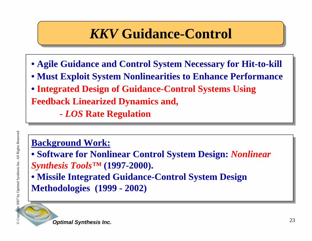
Recursive Backstepping MethodKKV Guidance-ControlKKV Guidance-Control
• Agile Guidance and Control System Necessary for Hit-to-kill• Must Exploit System Nonlinearities to Enhance Performance • Integrated Design of Guidance-Control Systems Using Feedback Linearized Dynamics and,
- LOS Rate Regulation
Background Work:• Software for Nonlinear Control System Design: Nonlinear Synthesis Tools™ (1997-2000).• Missile Integrated Guidance-Control System Design Methodologies (1999 - 2002)
24Optimal Synthesis Inc.©C
opyr
ight
200
7 by
Opt
imal
Syn
thes
is In
c. A
ll R
ight
s Res
erve
d
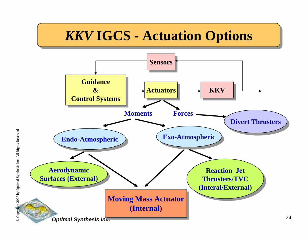
Recursive Backstepping MethodKKV IGCS - Actuation OptionsKKV IGCS - Actuation Options
Moments Forces
KKVKKV
SensorsSensors
ActuatorsActuatorsGuidance
&Control Systems
Guidance&
Control Systems
Endo-AtmosphericEndo-Atmospheric Exo-AtmosphericExo-Atmospheric
AerodynamicSurfaces (External)
AerodynamicSurfaces (External)
Reaction JetThrusters/TVC
(Interal/External)
Reaction JetThrusters/TVC
(Interal/External)
Divert ThrustersDivert Thrusters
Moving Mass Actuator(Internal)
Moving Mass Actuator(Internal)

25Optimal Synthesis Inc.©C
opyr
ight
200
7 by
Opt
imal
Syn
thes
is In
c. A
ll R
ight
s Res
erve
d
Recursive Backstepping MethodMoving-Mass Actuators for KKVMoving-Mass Actuators for KKV
Principle of Operation: Moving Masses Alter the CG Location of the KW, thereby Creating Control Moments from External Forces
Principle of Operation: Moving Masses Alter the CG Location of the KW, thereby Creating Control Moments from External Forces
MovingMasses
NominalCenter
ofMass (C.M)
C.MAfter Moving
the Masses
Thrust
XB
YB
ZB

26Optimal Synthesis Inc.©C
opyr
ight
200
7 by
Opt
imal
Syn
thes
is In
c. A
ll R
ight
s Res
erve
d
Recursive Backstepping MethodCharacteristics of Internal ActuatorsCharacteristics of Internal Actuators
Advantages:1. Effective in any Speed Range (Endo and Exo-Atmospheric Flight)2. Contained within the KKV Geometric Envelope.3. No Mass Expulsion
Disadvantages:Complex, Nonlinear System Dynamics
- Potential Non-minimum Phase Behavior- Variable Speed of Response- Atmospheric Performance can be Sensitive to Center of Pressure Uncertainty.

27Optimal Synthesis Inc.©C
opyr
ight
200
7 by
Opt
imal
Syn
thes
is In
c. A
ll R
ight
s Res
erve
d
Recursive Backstepping MethodEngagement GeometryEngagement Geometry
λz
λy
xV
yVzV
Vehicle-carried�inertial frame
Line Of Sight
xN
yNzN
Earth-fixed�(North-East-Down)�inertial frame
⎟⎟⎠
⎞⎜⎜⎝
⎛= −
x
y1y r
rtanλ ⎟⎟
⎠
⎞⎜⎜⎝
⎛= −
x
z1z r
rtanλ
2yxyx
y2
x
yxyy r
rrrrsecr
tanrr &&&&&
−=
−=
λλ
λ 2zxzx
z2
x
zxzz r
rrrrsecr
tanrr &&&&& −=
−=
λλ
λ
( ) 212
z2y
2x rrrr ++=[ ]Tzyx rrrr =
r
tsinAzORgz,0y,0x 2 ωω==== &&&&&&&&Target Model:
Line-of-Sight Angles:
Line-of-Sight Rates:
28Optimal Synthesis Inc.©C
opyr
ight
200
7 by
Opt
imal
Syn
thes
is In
c. A
ll R
ight
s Res
erve
d
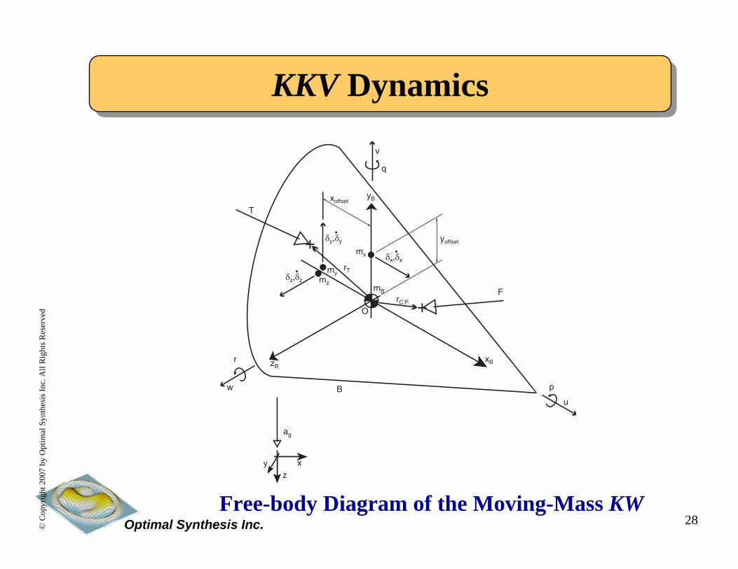
Recursive Backstepping MethodKKV DynamicsKKV Dynamics
Free-body Diagram of the Moving-Mass KW
xB
yB
y x�
z�
B
zB�
O
T
+
+
my
mx
mB
rC.P.
rT
�
v
u
w
q
p
r
�
Fmz
yoffset
xoffset
ag
δx,δx
δy,δy
δz,δz•
•
•

29Optimal Synthesis Inc.©C
opyr
ight
200
7 by
Opt
imal
Syn
thes
is In
c. A
ll R
ight
s Res
erve
d
Recursive Backstepping MethodKKV DynamicsKKV Dynamics
First-Order Moving-Mass Positioning Actuator Dynamics
0
5
10
15
20
0
10
20
30
40
500
0.1
0.2
0.3
0.4
0.5
0.6
0.7
MachAOA (deg)
Axi
al F
orce
Coe
ffici
ent C
A
0
5
10
15
20
0
10
20
30
40
500
0.5
1
1.5
2
2.5
3
3.5
4
MachAOA (deg)
Nor
mal
For
ce C
oeffi
cien
t CN
AC NC
KW Mass: 55 lbsKW Diameter: 1 ft.Actuator Masses: 5 lbs Each
Aerodynamic Coefficients (Neutrally Stable):

30Optimal Synthesis Inc.©C
opyr
ight
200
7 by
Opt
imal
Syn
thes
is In
c. A
ll R
ight
s Res
erve
d
Integrated Guidance-Control by LOS Rate Regulation
Integrated Guidance-Control by LOS Rate Regulation
IGC Philosophy:1. Apply Force uz on the Pitch Moving Mass to Position it at δz along the z-body axis, so as to Generate Pitch Rate qand Consequently a Lateral Velocity w to Drive the Pitch Component of the LOS Rate to Zero (While Stabilizing the Pitch Axis Dynamics).
2. Apply Force uy on the Yaw Moving Mass to Position it at δz along the z-body axis, so as to Generate Yaw Rate rand Consequently a Lateral Velocity v to Drive the Yaw Component of the LOS Rate to Zero (While Stabilizing the Yaw Axis Dynamics).
31Optimal Synthesis Inc.©C
opyr
ight
200
7 by
Opt
imal
Syn
thes
is In
c. A
ll R
ight
s Res
erve
d
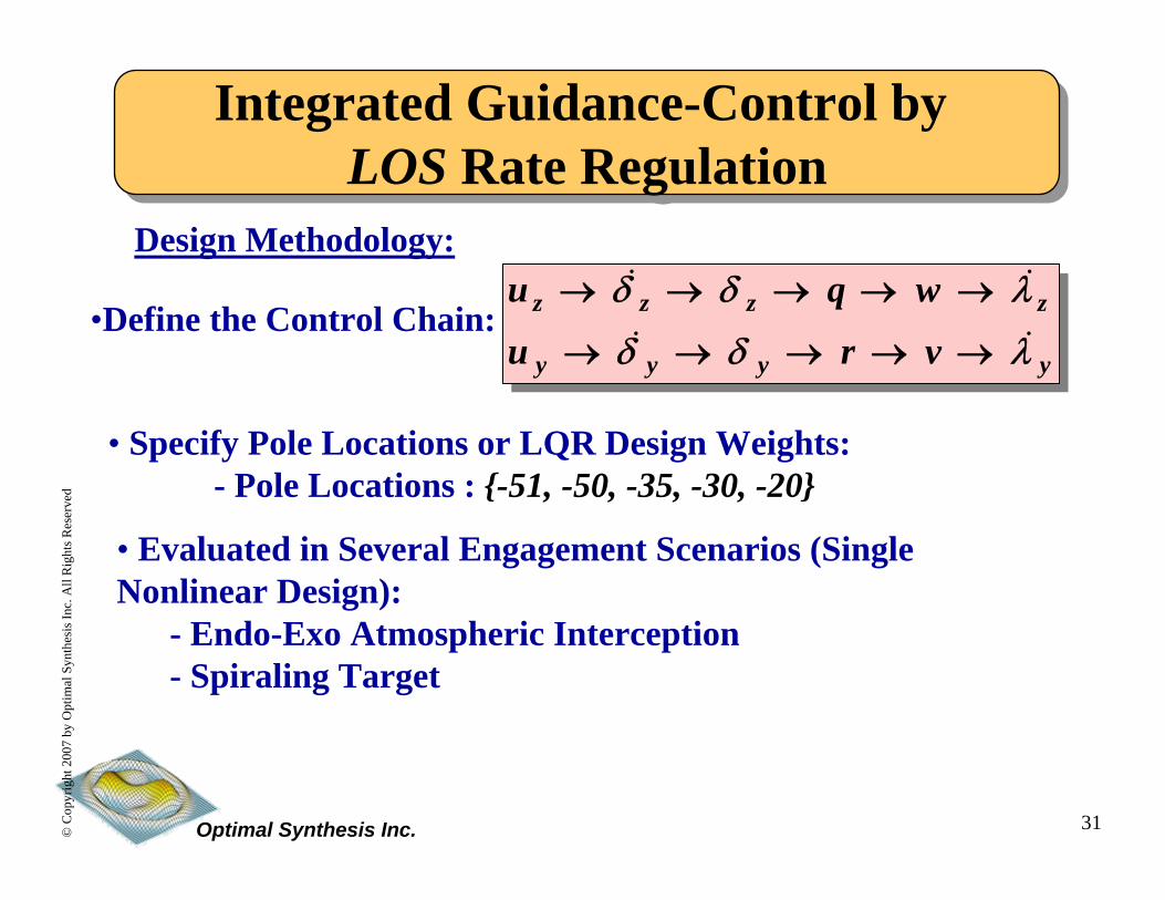
•Define the Control Chain:
Integrated Guidance-Control by LOS Rate Regulation
Integrated Guidance-Control by LOS Rate Regulation
yyyy
zzzz
vru
wqu
λδδ
λδδ&&
&&
→→→→→
→→→→→Design Methodology:
• Specify Pole Locations or LQR Design Weights:- Pole Locations : {-51, -50, -35, -30, -20}
• Evaluated in Several Engagement Scenarios (Single Nonlinear Design):
- Endo-Exo Atmospheric Interception- Spiraling Target

32Optimal Synthesis Inc.©C
opyr
ight
200
7 by
Opt
imal
Syn
thes
is In
c. A
ll R
ight
s Res
erve
d
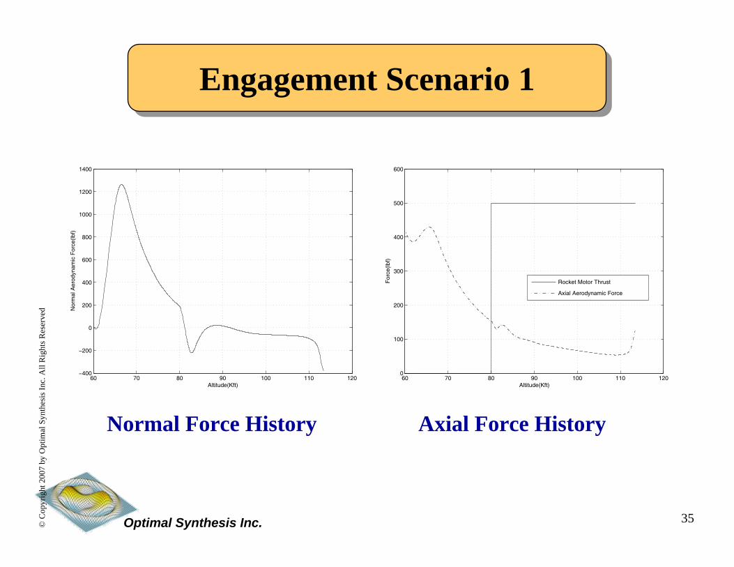
Recursive Backstepping MethodEngagement Scenario 1Engagement Scenario 1
Miss Distance: 0.17 ft

33Optimal Synthesis Inc.©C
opyr
ight
200
7 by
Opt
imal
Syn
thes
is In
c. A
ll R
ight
s Res
erve
d
Recursive Backstepping Method
0 0.5 1 1.5 2 2.5 3 3.5 4 4.5 5
x 104
0.6
0.7
0.8
0.9
1
1.1
1.2
1.3
1.4
1.5
1.6x 10
5
North Position (ft)
Alti
tude
(ft)
warheadtarget
Vertical Plane Trajectories Horizontal Plane Trajectories
0 0.5 1 1.5 2 2.5 3 3.5 4 4.5 5
x 104
0
500
1000
1500
2000
2500
North Position (ft)
Eas
t Pos
ition
(ft)
warheadtarget
Engagement Scenario 1Engagement Scenario 1

34Optimal Synthesis Inc.©C
opyr
ight
200
7 by
Opt
imal
Syn
thes
is In
c. A
ll R
ight
s Res
erve
d
Recursive Backstepping Method
0 1 2 3 4 5 6 7 8 9 10−50
−40
−30
−20
−10
0
10
20
Time (sec)A
ngle
(de
g)
aero angles α,β
βα
Body Rate Histories α, β Histories
0 1 2 3 4 5 6 7 8 9 10−3
−2
−1
0
1
2
3
Time (sec)
Ang
ular
Vel
ocity
(ra
d/se
c)
vehicle angular rates p,q,r
pqr
Engagement Scenario 1Engagement Scenario 1
35Optimal Synthesis Inc.©C
opyr
ight
200
7 by
Opt
imal
Syn
thes
is In
c. A
ll R
ight
s Res
erve
d
Recursive Backstepping Method
60 70 80 90 100 110 120−400
−200
0
200
400
600
800
1000
1200
1400
Altitude(Kft)
Nor
mal
Aer
odyn
amic
For
ce(lb
f)
Normal Force History
Engagement Scenario 1Engagement Scenario 1
60 70 80 90 100 110 1200
100
200
300
400
500
600
For
ce(lb
f)Altitude(Kft)
Rocket Motor Thrust
Axial Aerodynamic Force
Axial Force History

36Optimal Synthesis Inc.©C
opyr
ight
200
7 by
Opt
imal
Syn
thes
is In
c. A
ll R
ight
s Res
erve
d
Recursive Backstepping Method
Body Acceleration Histories
Engagement Scenario 1Engagement Scenario 1
60 70 80 90 100 110 120−20
−15
−10
−5
0
5
10
Altitude(Kft)
Acc
eler
atio
n(G
s)
Body Frame Acceleration Components
ay
az

37Optimal Synthesis Inc.©C
opyr
ight
200
7 by
Opt
imal
Syn
thes
is In
c. A
ll R
ight
s Res
erve
d
Recursive Backstepping MethodInterception of a Spiraling TargetInterception of a Spiraling TargetKKV: 45 Kft Altitude , 50 deg Flight Path AngleTarget: 90 Kft Altitude, 50Kft North, -35 deg Flight Path Angle, 1g Lateral Acceleration, 3 Rad/s Frequency, Reciprocal Heading
Miss Distance: 0.25 ft

38Optimal Synthesis Inc.©C
opyr
ight
200
7 by
Opt
imal
Syn
thes
is In
c. A
ll R
ight
s Res
erve
d
Recursive Backstepping Method
0 0.5 1 1.5 2 2.5 3 3.5 4 4.5 5
x 104
4.5
5
5.5
6
6.5
7
7.5
8
8.5
9x 10
4
North Position (ft)
Alti
tude
(ft)
warheadtarget
Interception of a Spiraling TargetInterception of a Spiraling Target
0 0.5 1 1.5 2 2.5 3 3.5 4 4.5 5
x 104
−35
−30
−25
−20
−15
−10
−5
0
5
10
North Position (ft)E
ast P
ositi
on (
ft)
warheadtarget
Trajectories in the Horizontal and Vertical Plane

39Optimal Synthesis Inc.©C
opyr
ight
200
7 by
Opt
imal
Syn
thes
is In
c. A
ll R
ight
s Res
erve
d
Recursive Backstepping Method
0 1 2 3 4 5 6 7−2
0
2
4
6
8
10
12
Time (sec)A
ccel
erat
ion
(g)
body accelerations
az
ay
Interception of a Spiraling TargetInterception of a Spiraling Target
−5
0
5
10
−100102030405060
1.35
1.4
1.45
1.5
1.55
1.6
1.65
1.7
1.75
1.8
x 105
East Position(ft)
North Position(ft)
Alti
tude
(ft)
Target Trajectory After Removing the Secular Component
Pitch-Yaw Acceleration Histories

40Optimal Synthesis Inc.©C
opyr
ight
200
7 by
Opt
imal
Syn
thes
is In
c. A
ll R
ight
s Res
erve
d
Recursive Backstepping MethodReal-Time Simulation Real-Time Simulation

41Optimal Synthesis Inc.©C
opyr
ight
200
7 by
Opt
imal
Syn
thes
is In
c. A
ll R
ight
s Res
erve
d
Recursive Backstepping MethodSummarySummary
• Discussed Integrated Guidance-Control System Design Methods
- Eliminates Iterative Design Process- Eliminates Spurious Effects Induced by more Traditional Design Methods
- Better Satisfaction of Design Objectives- Synergistic Design
• Illustrated IGC Design for Air-to-Air Missile and an Internally Actuated KKV.
- Nonlinear Control Techniques- Computer-Aided Nonlinear System Design- ZEM, LOS Rate, Terminal-Miss Design Strategies
• Being Investigated for Designing Flight Control Systems of other Vehicles.