instruction model fd20 ph/orp manual immersion fittings · the model fd20 immersion fittings are...
TRANSCRIPT
IM 12B06K02-01E-E9th edition
InstructionManual
Model FD20Immersion Fittings
pH/ORP
YOKOGAWA
IM12B06K02-01E-E_ed09.indd 1 07/03/16 09:51

IM 12B06K02-01E-E
2
IM12B06K02-01E-E_ed09.indd 2 07/03/16 09:51
IM12B06K02-01E-E
3
Contents1. Introduction 5 1.1 Features 5 1.2 Unpacking and Checking 5 1.3 Warranty and Service 5 1.4 Serial Number definition 6
2. Specifications 7 2.1 General specifications 7 2.2 Functional specifications 7 2.3 Model and codes 8 2.4 External dimensions 9
3. Installation 12 3.1 Selecting the installation site 12 3.2 Installation 12 3.2.1 “Hoisting eye” type mounting 12 3.2.2 Flange mounting fitting 12 3.3 Cables and sensor mounting 13 3.3.1 1-Hole fitting 13 3.3.2 3-Hole and 4-hole fitting 15
4. Mounting of Accessoires 16 4.1 Mounting kit option /B (FP20-S13) 16 4.2 Mounting kit option /R, (order nr. K1500BY) 17 4.3 Cleaning systems 18 4.3.1 Selection criteria 18 4.3.2 Brush cleaning 19 4.3.3 Chemical cleaning 20 4.4 Salt bridge 21 4.5 Protection hose installation kit 21
5. Maintenance and Inspection 22 5.1 Cleaning and fitting 22 5.2 Inspection of the O-ring seal 22
6. Spare Parts 22
IM12B06K02-01E-E_ed09.indd 3 07/03/16 09:51
IM 12B06K02-01E-E
4
IM12B06K02-01E-E_ed09.indd 4 07/03/16 09:51
IM12B06K02-01E-E
5
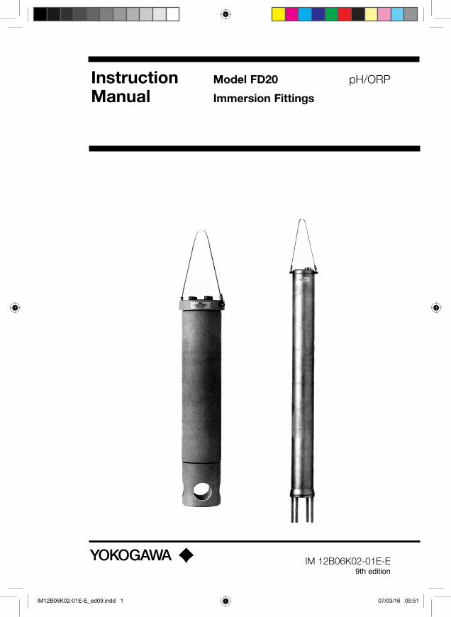
The model FD20 immersion fittings are used to submerge sensor tips so that the pH and/or ORP (redox) potential of liquids in open vessels, tanks, drains etc. can be measured.
The fittings are available for mounting of either: - one electrode
- three electrodes - four electrodes or alternatively three
electrodes and a cleaning system.
1.1 Features• Designed for either pH or ORP measure-
ments in tanks, open vessels and drains.• “Hoisting cable” for easy maintenance.• Pre-selected immersion length.• Wide choice of construction materials.• Flange mounting.• High degree of standardisation reduces
spare holding requirements.• Liquid earth pin for stable measurements.• Chemical or brush cleaning systems as
an option.
1.2 Unpacking and CheckingUpon delivery, unpack the fitting carefully and inspect it to ensure that it is not damaged during shipment. If damage is found, retain the original packing material and immediately notify the carrier and the relevant local Yokogawa Sales Office. Make sure the Model Code and Serial Number on the sensor are the same as on the packing list. Also check if option(s) that were ordered, are included and correct.
1.3 Warranty and ServiceYokogawa products are guaranteed free from defects in workmanship and materials under normal use and service for a period of (typically) 12 months from the date of shipment from the manufacturer. Individual Sales organizations can deviate from the typical warranty period, and the conditions of sale relating to the original purchase order should be consulted. Damage caused by wear and tear, inadequate maintenance, corrosion, or by the effects of chemical
processes is excluded from this warranty coverage. In the event of a warranty claim, the defective goods should be sent (freight paid) to the Service Department of the relevant Yokogawa Sales office for repair or replacement (at Yokogawa’s discretion).
The following information must be included in the letter accompanying the returned goods:• Model Code and Serial Number.• Original Purchase Order and Date.• Length of time in service and description of
the process.• Description of the fault and circumstances
of the failure.• Process/environmental conditions that may
be related to the failure of the sensor.• Statement as to whether warranty or non-
warranty service is requested.• Complete shipping and billing instructions
for return of material, plus the name and phone number of a contact person that can be reached for further information.
• Clean Statement Returned goods that have been in contact with process fluids must be decontaminated and disinfected prior to shipment. Goods should carry a certificate to this effect, for the health and safety of our employees. Material Safety Data sheets must be included for all components of the process to which the fitting(options) have been exposed.
1. Introduction
IM12B06K02-01E-E_ed09.indd 5 07/03/16 09:51
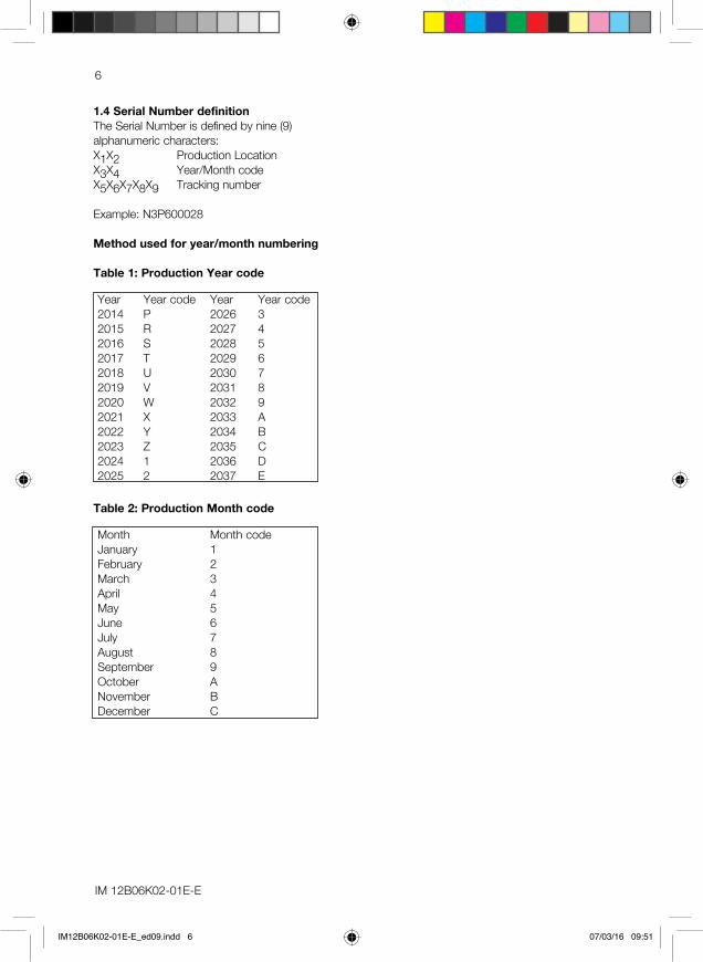
1.4 Serial Number definitionThe Serial Number is defined by nine (9) alphanumeric characters:X1X2 Production Location X3X4 Year/Month code X5X6X7X8X9 Tracking number Example: N3P600028
Method used for year/month numbering
Table 1: Production Year code
Year Year code Year Year code2014 P 2026 32015 R 2027 42016 S 2028 52017 T 2029 62018 U 2030 72019 V 2031 82020 W 2032 92021 X 2033 A2022 Y 2034 B2023 Z 2035 C2024 1 2036 D2025 2 2037 E
Table 2: Production Month code
Month Month codeJanuary 1February 2March 3April 4May 5June 6July 7August 8September 9October ANovember BDecember C
IM 12B06K02-01E-E
6
IM12B06K02-01E-E_ed09.indd 6 07/03/16 09:51

2. Specifications
2.1 General specifications
Materials- wetted parts A. body (refer to model code) : polyproplylene (PP)
stainless steel AISI 316 (SS) polyvinylchloride (PVC) polyvinylidenefluoride (PVDF)
B. O-rings : silicone rubber C. liquid earth sensor : titanium (PP and PVDF design)
(not in 1-hole fitting) stainless steel AISI 316 (SS design)- electrode mounting sets : PPS (Ryton™)- “hoisting eye” : stainless steel cable (twisted)
Weight* : see tabel 1
Table 1
* The accessories are not included. The noted weights are at an immersion length of 1 m.
Mounting : by means of the “hoisting eye” or flange mounting
2.2 Functional specifications
Temperature- min. : -10°C- max. : depending on material and application (see
figure 2.1)Immersion length (in dm) : between 0,5 and 2,0 mPressure : see figure 2.1 : 3 bar for PP, PVDF and PVC Flange
Fig. 2.1 Pressure/temperature class
Material PVC PP SS PVDFFitting1-hole fitting 0,4 kg 3-hole fitting 2 kg 5,3 kg 2,5 kg4-hole fitting 4,5 kg 6,4 kg 5,5 kg
0 10 20 30 40 50 60 70 80 100 120 140 160
bar
2
4
6
8
10
12
AISI 316
PVDF
PPPVC
IM12B06K02-01E-E
7
IM12B06K02-01E-E_ed09.indd 7 07/03/16 09:51
IM 12B06K02-01E-E
8
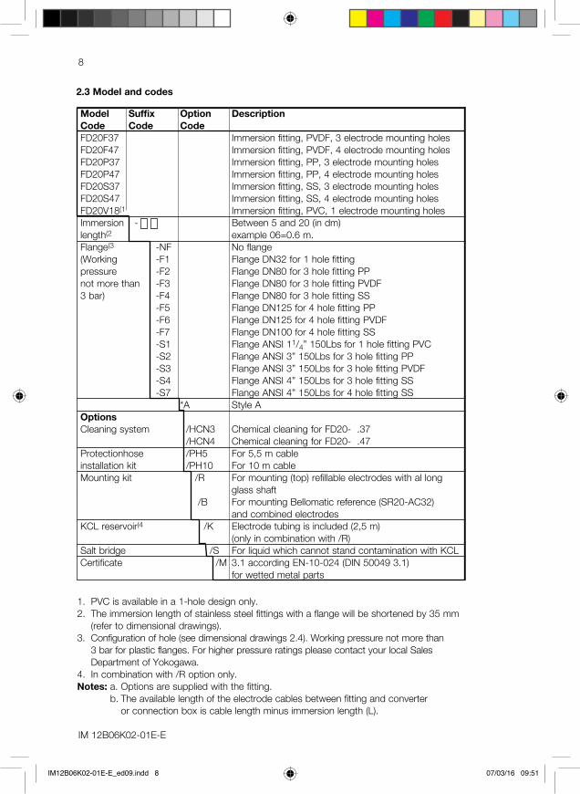
2.3 Model and codes
1. PVC is available in a 1-hole design only.2. The immersion length of stainless steel fittings with a flange will be shortened by 35 mm
(refer to dimensional drawings).3. Configuration of hole (see dimensional drawings 2.4). Working pressure not more than
3 bar for plastic flanges. For higher pressure ratings please contact your local Sales Department of Yokogawa.
4. In combination with /R option only.Notes: a. Options are supplied with the fitting.
b. The available length of the electrode cables between fitting and converter or connection box is cable length minus immersion length (L).
Model Suffix Option Description Code Code CodeFD20F37 Immersion fitting, PVDF, 3 electrode mounting holesFD20F47 Immersion fitting, PVDF, 4 electrode mounting holesFD20P37 Immersion fitting, PP, 3 electrode mounting holesFD20P47 Immersion fitting, PP, 4 electrode mounting holesFD20S37 Immersion fitting, SS, 3 electrode mounting holesFD20S47 Immersion fitting, SS, 4 electrode mounting holesFD20V18(1 Immersion fitting, PVC, 1 electrode mounting holesImmersion - Between 5 and 20 (in dm)length(2 example 06=0.6 m.Flange(3 -NF No flange(Working -F1 Flange DN32 for 1 hole fittingpressure -F2 Flange DN80 for 3 hole fitting PPnot more than -F3 Flange DN80 for 3 hole fitting PVDF3 bar) -F4 Flange DN80 for 3 hole fitting SS -F5 Flange DN125 for 4 hole fitting PP -F6 Flange DN125 for 4 hole fitting PVDF -F7 Flange DN100 for 4 hole fitting SS -S1 Flange ANSI 11/4” 150Lbs for 1 hole fitting PVC -S2 Flange ANSI 3” 150Lbs for 3 hole fitting PP -S3 Flange ANSI 3” 150Lbs for 3 hole fitting PVDF -S4 Flange ANSI 4” 150Lbs for 3 hole fitting SS -S7 Flange ANSI 4” 150Lbs for 4 hole fitting SS *A Style AOptionsCleaning system /HCN3 Chemical cleaning for FD20- .37 /HCN4 Chemical cleaning for FD20- .47Protectionhose /PH5 For 5,5 m cableinstallation kit /PH10 For 10 m cableMounting kit /R For mounting (top) refillable electrodes with al long
glass shaft /B For mounting Bellomatic reference (SR20-AC32)
and combined electrodesKCL reservoir(4 /K Electrode tubing is included (2,5 m)
(only in combination with /R)Salt bridge /S For liquid which cannot stand contamination with KCLCertificate /M 3.1 according EN-10-024 (DIN 50049 3.1)
for wetted metal parts
IM12B06K02-01E-E_ed09.indd 8 07/03/16 09:51

IM12B06K02-01E-E
9
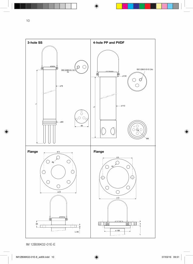
2.4 External dimensions
ø90
ø75
ISO 228/2-G 1/2(2x)
ø k
ø D
ø 125
b
dgø dg
ø D
ø k
b
ø 30
ø 25
ø 40
L
ISO 228/2-G1/2
1-hole PVC 3-hole PP and PVDF
Flange Flange
IM12B06K02-01E-E_ed09.indd 9 07/03/16 09:51
ø k
ø D
b35
dg
L-35
L
ø130
ø110
M8
ISO 228/2-G1/2 (3x)
L
ø76
ø80
ISO 228/2-G 1/22x
80
10
3-hole SS
b
ø 188
ø k
ø D
L
dg
4-hole PP and PVDF
IM 12B06K02-01E-E
FlangeFlange
IM12B06K02-01E-E_ed09.indd 10 07/03/16 09:51

11
L
ø 88
ISO 228/2-G 1/2(3x)
M8ø 100
L-35
b
ø D
ø k
dg
35
4-hole SS Flange
L D k dg bFD20-V18-..-NF 5-20dmFD20-V18-..-F1 5-20dm 120 90 14 26FD20-V18-..-S1 5-20dm 120 90 16 26FD20-P37-..-NF 5-20dmFD20-F37-..-NF 5-20dmFD20-P37-..-F2 5-20dm 200 160 18 20FD20-F37-..-F3 5-20dm 200 160 18 20FD20-P37-..-S2 5-20dm 190 152.4 20 18FD20-F37-..-S3 5-20dm 190 152,4 20 18FD20-S37-..-NF 5-20dmFD20-S37-..-F4 5-20dm 200 160 18 20FD20-S37-..-S4 5-20dm 228,6 190,5 19 23,8FD20-P47-..-NF 5-20dmFD20-F47-..-NF 5-20dmFD20-P47-..-F5 5-20dm 250 210 18 24FD20-F47-..-F6 5-20dm 250 210 18 24FD20-S47-..-NF 5-20dmFD20-S47-..-F7 5-20dm 220 180 18 20FD20-S47-..-S7 5-20dm 228,6 190,5 19 23,8
unit in mm
IM12B06K02-01E-E
IM12B06K02-01E-E_ed09.indd 11 07/03/16 09:51
IM 12B06K02-01E-E
12
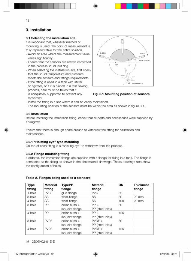
3. Installation
3.1 Selecting the installation siteIt is important that, whatever method of mounting is used, the point of measurement is truly representative for the entire solution.- Avoid an area where the measurement value
varies significantly.- Ensure that the sensors are always immersed
in the process liquid (not dry).- When selecting the installation site, first check
that the liquid temperature and pressure meets the sensors and fittings requirements.
- If the fitting is used in a tank with stirrer or agitator, or if it is placed in a fast flowing process, care must be taken that it is adequately supported to prevent any movement.
- Install the fitting in a site where it can be easily maintained. The mounting position of the sensors must be within the area as shown in figure 3.1.
3.2 InstallationBefore installing the immersion fitting, check that all parts and accessories were supplied by Yokogawa.
Ensure that there is enough spare around to withdraw the fitting for calibration and maintenance.
3.2.1 “Hoisting eye” type mountingOn top of each fitting is a “hoisting eye” to withdraw from the process.
3.2.2 Flange mounting fittingIf ordered, the immersion fittings are supplied with a flange for fixing in a tank. The flange is connected to the fitting as shown in the dimensional drawings. These drawings also show the configuration of holes.
Table 2. Flanges being used as a standard
INCORRECT
15º 15º
HORIZONTAL
GOOD GOOD
Fig. 3.1 Mounting position of sensors
Type Material TypePP Material DN Thickness fitting fitting flange flange flange1-hole PVC glue-flange PVC 323-hole SS weld-flange SS 80 20 mm4-hole SS weld-flange SS 100 20 mm3-hole PP collar-bush + PP + 80 lap-joint flange PP (steal inlay)4-hole PP collar-bush + PP + 125 lap-joint flange PP (steal inlay)3-hole PVDF collar-bush + PVDF + 80 lap-joint flange PP (steal inlay)4-hole PVDF collar-bush + PVDF + 125 lap-joint flange PP (steal inlay)
IM12B06K02-01E-E_ed09.indd 12 07/03/16 09:51
IM12B06K02-01E-E
13
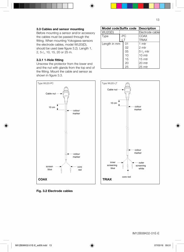
3.3 Cables and sensor mountingBefore mounting a sensor and/or accessory the cables must be passed through the fitting. When mounting Yokogawa sensors the electrode cables, model WU20(D), should be used (see figure 3.2). Length 1, 2, 51/2, 10, 15, 20 or 25 m.
3.3.1 1-Hole fittingUnscrew the protector from the lower end and the nut with glands from the top end of the fitting. Mount the cable and sensor as shown in figure 3.3.
Fig. 3.2 Electrode cables
Model code Suffix code DescriptionWU20(D) Electrode cableType -PC COAX -LT TRIAXLength in mm 01 1 mtr 02 2 mtr 05 51/2 mtr 10 10 mtr 15 15 mtr 20 20 mtr 25 25 mtr
10 cm
colour
marker
colour
marker
screen
blue
core
red
10 cm
colour
marker
colour
marker
outer
screening
white
core red
inner
screening
blue
Cable nut Cable nut
10 cm
colour
marker
colour
marker
screen
blue
core
red
10 cm
colour
marker
colour
marker
outer
screening
white
core red
inner
screening
blue
Cable nut Cable nut
COAX TRIAX
Type WU20-PC Type WU20-LT
IM12B06K02-01E-E_ed09.indd 13 07/03/16 09:51
IM 12B06K02-01E-E
14
10 cm
colour
marker
colour
marker
screen
blue
core
red
10 cm
colour
marker
colour
marker
outer
screening
white
core red
inner
screening
blue
Cable nut Cable nut
10 cm
colour
marker
colour
marker
screen
blue
core
red
10 cm
colour
marker
colour
marker
outer
screening
white
core red
inner
screening
blue
Cable nut Cable nut
COAX TRIAX
Type WU20D-PC Type WU20D-LT
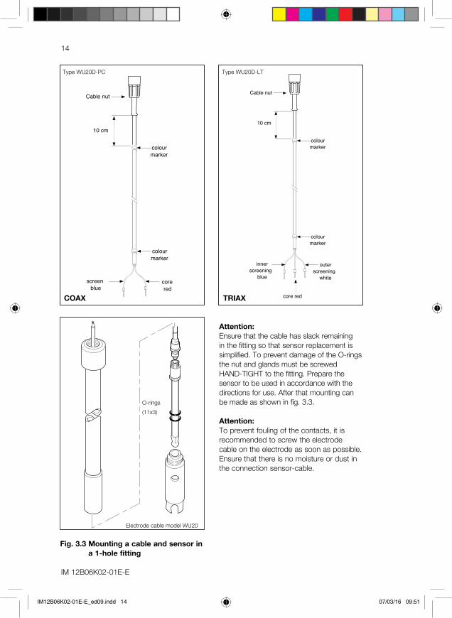
Fig. 3.3 Mounting a cable and sensor in a 1-hole fitting
O-rings (11x3)
Electrode cable model WU20
Attention:Ensure that the cable has slack remaining in the fitting so that sensor replacement is simplified. To prevent damage of the O-rings the nut and glands must be screwed HAND-TIGHT to the fitting. Prepare the sensor to be used in accordance with the directions for use. After that mounting can be made as shown in fig. 3.3.
Attention:To prevent fouling of the contacts, it is recommended to screw the electrode cable on the electrode as soon as possible. Ensure that there is no moisture or dust in the connection sensor-cable.
IM12B06K02-01E-E_ed09.indd 14 07/03/16 09:51
IM12B06K02-01E-E
15
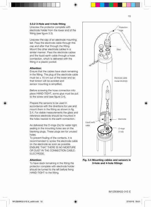
3.3.2 3-Hole and 4-hole fittingUnscrew the protector complete with electrode holder from the lower end of the fitting (see figure 3.3).
Unscrew the cap of an electrode mounting set. Pass the electrode cable through this cap and after that through the fitting.Mount the other electrode cables in a similar manner. Pass the electrode cables and the liquid earth cable through a hose connection, which is delivered with the fitting in a plastic pocket.
Attention:Ensure that the cables have slack remaining in the fitting. The plug of the electrode cable must be ± 15 cm out of the lower end so that torsion will be avoided and sensor mounting is simplified.
Before screwing the hose connection into place HAND-TIGHT, some glue must be put to the screw end (see figure 3.4).
Prepare the sensors to be used in accordance with the directions for use and mount them in the fitting as shown in fig. 3.4. For stable measurements the glass and reference electrode should be mounted in the holes nearest to the earth connection.
As delivered the O-rings (2x) for water-tight sealing in the mounting holes are on the blanking plugs. These plugs are for unused holes.To prevent fouling of the contacts, it is recommended to screw the electrode cable on the electrode as soon as possible.ENSURE THAT THERE IS NO MOISTURE OR DUST IN THE CONNECTION CABLE-ELECTRODE.
Attention:To have slack remaining in the fitting the protector complete with electrode holder should be turned to the left before fixing HAND-TIGHT to the fitting.
Fig. 3.4 Mounting cables and sensors in 3-hole and 4-hole fittings
Liquid earth cable
Electrode cable model WU20(D)
Electrode
O-rings (11x3)
Glue
Protection hose
IM12B06K02-01E-E_ed09.indd 15 07/03/16 09:51
IM 12B06K02-01E-E
16
4. Mounting of Accessoires
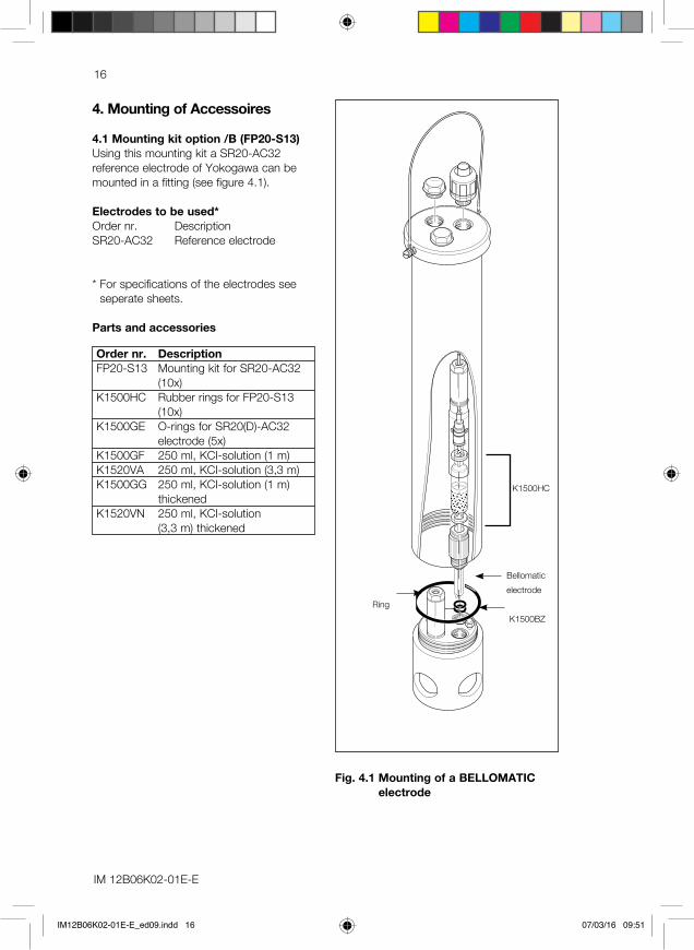
4.1 Mounting kit option /B (FP20-S13)Using this mounting kit a SR20-AC32 reference electrode of Yokogawa can be mounted in a fitting (see figure 4.1).
Electrodes to be used*Order nr. DescriptionSR20-AC32 Reference electrode
* For specifications of the electrodes see seperate sheets.
Parts and accessories
Order nr. DescriptionFP20-S13 Mounting kit for SR20-AC32 (10x)K1500HC Rubber rings for FP20-S13 (10x)K1500GE O-rings for SR20(D)-AC32
electrode (5x)K1500GF 250 ml, KCI-solution (1 m)K1520VA 250 ml, KCI-solution (3,3 m)K1500GG 250 ml, KCI-solution (1 m)
thickenedK1520VN 250 ml, KCI-solution
(3,3 m) thickened
Fig. 4.1 Mounting of a BELLOMATIC electrode
Bellomatic electrode
Ring K1500BZ
K1500HC
IM12B06K02-01E-E_ed09.indd 16 07/03/16 09:51
IM12B06K02-01E-E
17
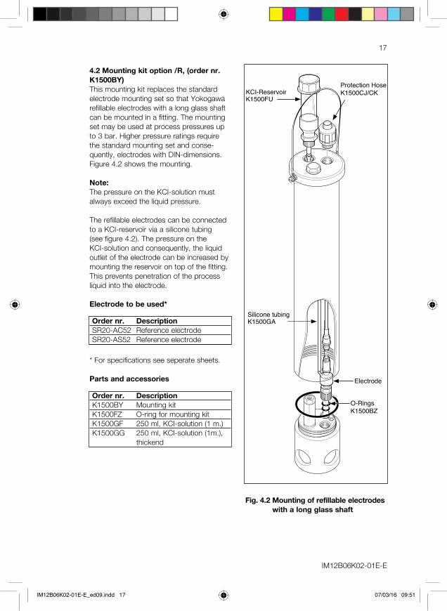
KCI-ReservoirK1500FU
Silicone tubingK1500GA
O-RingsK1500BZ
Electrode
Protection HoseK1500CJ/CK
Fig. 4.2 Mounting of refillable electrodes with a long glass shaft
4.2 Mounting kit option /R, (order nr. K1500BY)This mounting kit replaces the standard electrode mounting set so that Yokogawa refillable electrodes with a long glass shaft can be mounted in a fitting. The mounting set may be used at process pressures up to 3 bar. Higher pressure ratings require the standard mounting set and conse-quently, electrodes with DIN-dimensions.Figure 4.2 shows the mounting.
Note:The pressure on the KCI-solution must always exceed the liquid pressure.
The refillable electrodes can be connected to a KCI-reservoir via a silicone tubing (see figure 4.2). The pressure on the KCI-solution and consequently, the liquid outlet of the electrode can be increased by mounting the reservoir on top of the fitting. This prevents penetration of the process liquid into the electrode.
Electrode to be used*
Order nr. DescriptionSR20-AC52 Reference electrodeSR20-AS52 Reference electrode
* For specifications see seperate sheets.
Parts and accessories
Order nr. DescriptionK1500BY Mounting kitK1500FZ O-ring for mounting kitK1500GF 250 ml, KCI-solution (1 m.)K1500GG 250 ml, KCI-solution (1m.),
thickend
IM12B06K02-01E-E_ed09.indd 17 07/03/16 09:51
IM 12B06K02-01E-E
18
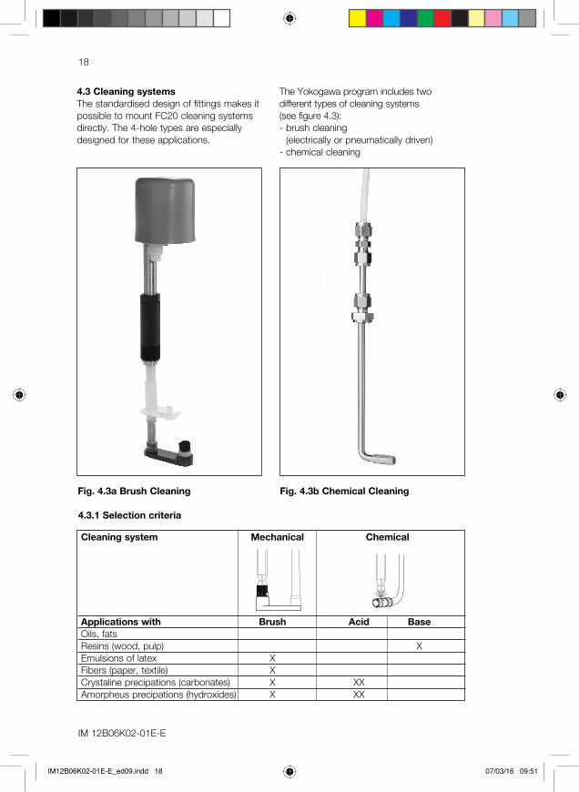
4.3 Cleaning systemsThe standardised design of fittings makes it possible to mount FC20 cleaning systems directly. The 4-hole types are especially designed for these applications.
The Yokogawa program includes two different types of cleaning systems (see figure 4.3):- brush cleaning
(electrically or pneumatically driven)- chemical cleaning
4.3.1 Selection criteria
Cleaning system Mechanical Chemical
Applications with Brush Acid BaseOils, fats Resins (wood, pulp) XEmulsions of latex XFibers (paper, textile) XCrystaline precipations (carbonates) X XXAmorpheus precipations (hydroxides) X XX
Fig. 4.3a Brush Cleaning Fig. 4.3b Chemical Cleaning
IM12B06K02-01E-E_ed09.indd 18 07/03/16 09:51
IM12B06K02-01E-E
19
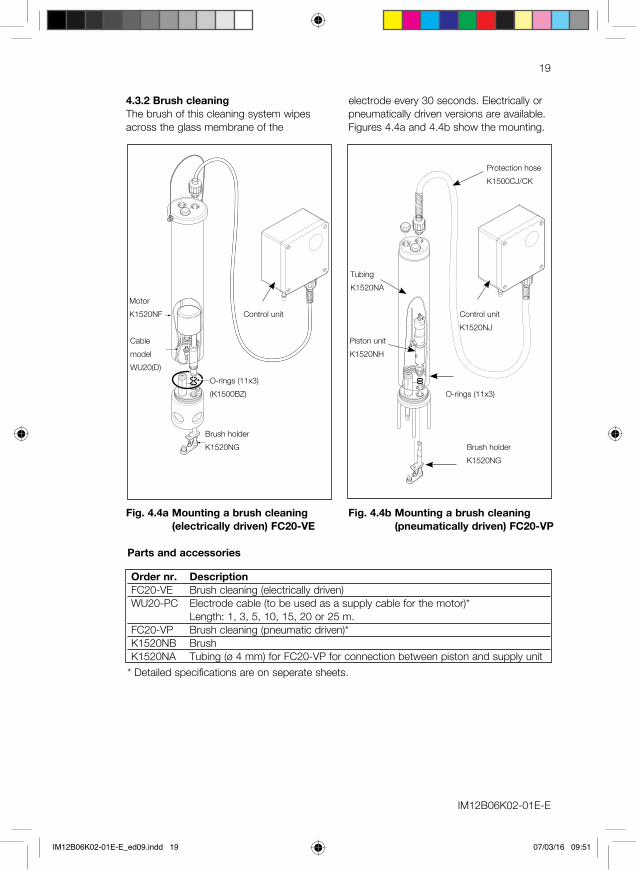
Fig. 4.4a Mounting a brush cleaning (electrically driven) FC20-VE
MotorK1520NF
Cable model WU20(D)
O-rings (11x3)(K1500BZ)
Brush holderK1520NG
Fig. 4.4b Mounting a brush cleaning (pneumatically driven) FC20-VP
O-rings (11x3)
Piston unitK1520NH
TubingK1520NA
Control unitK1520NJ
Protection hoseK1500CJ/CK
Brush holderK1520NG
4.3.2 Brush cleaningThe brush of this cleaning system wipes across the glass membrane of the
electrode every 30 seconds. Electrically or pneumatically driven versions are available.Figures 4.4a and 4.4b show the mounting.
Control unit
Parts and accessories
Order nr. DescriptionFC20-VE Brush cleaning (electrically driven)WU20-PC Electrode cable (to be used as a supply cable for the motor)*
Length: 1, 3, 5, 10, 15, 20 or 25 m.FC20-VP Brush cleaning (pneumatic driven)*K1520NB BrushK1520NA Tubing (ø 4 mm) for FC20-VP for connection between piston and supply unit
* Detailed specifications are on seperate sheets.
IM12B06K02-01E-E_ed09.indd 19 07/03/16 09:51
IM 12B06K02-01E-E
20
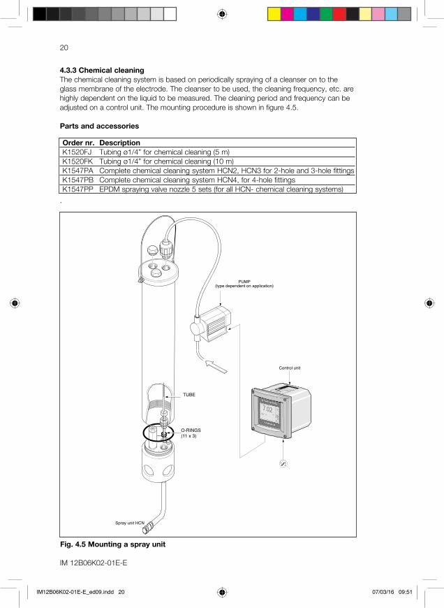
Spray unit HCN
O-RINGS(11 x 3)
PUMP(type dependent on application)
TUBE
Control unit
Fig. 4.5 Mounting a spray unit
4.3.3 Chemical cleaningThe chemical cleaning system is based on periodically spraying of a cleanser on to the glass membrane of the electrode. The cleanser to be used, the cleaning frequency, etc. are highly dependent on the liquid to be measured. The cleaning period and frequency can be adjusted on a control unit. The mounting procedure is shown in figure 4.5.
Parts and accessories
Order nr. DescriptionK1520FJ Tubing ø1/4” for chemical cleaning (5 m)K1520FK Tubing ø1/4” for chemical cleaning (10 m)K1547PA Complete chemical cleaning system HCN2, HCN3 for 2-hole and 3-hole fittingsK1547PB Complete chemical cleaning system HCN4, for 4-hole fittingsK1547PP EPDM spraying valve nozzle 5 sets (for all HCN- chemical cleaning systems)
.
IM12B06K02-01E-E_ed09.indd 20 07/03/16 09:51

IM12B06K02-01E-E
21
4.4 Salt bridgeThis reference electrode/salt bridge combination allows the measurement of pH and ORP (Redox) potentials with normal electrodes in those cases when: A. excessive contamination of the flow
diaphragm is expected. The flow of the reference liquid through the diaphragm is increased by pressurising the container. Consequently, the contamination rate will decrease.
B. the process to be measured cannot stand contamination with KCI. The salt bridge can be filled with several electrolytes, e.g. KNO3.
C. measurement has to be performed at pressures up to 10 bar and temperatures up to 100 °C. As the container with reference liquid can be pressurised.
FLOW TUBE (A)Material : glassFlow diaphragm : ceramic, PTFE or sleeveConnector : PPS (Ryton™)TUBING (B)Material : nylonDiameter : 1/4” o.d.Length : 2 mtr.CONTAINER (C)Container : PVC, PVC (transparent)Mounting set : PPS (Ryton™)O-ring : siliconeConnection : nylonWeight : approx. 300 g.Mounting : wall mounting (support
with hole for screw M5)Temperature/pressure ratio : max. 200 kPa
(2 bar) at 100°C
Parts and accessories
Order nr. DescriptionSB20-VC Salt bridge with ceramic junctionSB20-VP Salt bridge with porous PTFE
junctionSB20-VS Salt bridge with glass sleeve
junctionK1500DX 5m tubing for SB20K1500BW flow tube for SB20-VCK1500EE flow tube for SB20-VPK1500EF flow tube for SB20-VS
Note: The reference electrode must be ordered seperately.
4.5 Protection hose installation kitThe protection hose installation kit is for protection of electrode cable and/or tubing between fitting and converter, connecting box, supply unit, etc. The hoses can be mounted directly to the hose connection(s) on top of each fitting. Clamps for fixing are part of the installation kit.
Parts and accessories
Order nr. DescriptionK1500CJ Protection hose kit 5 mK1500CK Protection hose kit 10 m
REFERENCEELECTRODE
Fig. 4.6 Mounting the salt bridge
IM12B06K02-01E-E_ed09.indd 21 07/03/16 09:51

IM 12B06K02-01E-E
22
5. Maintenance and Inspection
5.1 Cleaning and fittingUsally no cleaning is necessary.
5.2 Inspection of the O-ring sealThe O-ring seal used in the wetted parts of the fitting is made of silicone rubber which has superior resistance to corrosion and is suitable for use with most process liquids.Usually no periodically inspection is necessary. To prevent trouble, replace the O-ring seal periodically, e.g. every year.
Note: For chemical resistance of the used material refer to General Specifications sheet GS 12B06K02-01E-E.
6. Spare Parts
Order nr. DescriptionK1500GR O-rings (11x3) for electrode mounting (8 pieces)K1500GU Set O-rings for 3-hole fitting (PP and PVDF)K1500FB (viton) Set O-rings for 3-hole fitting (PP and PVDF)K1500FA (EPDM) Set O-rings for 3-hole fitting (PP and PVDF)K1500GV Set O-rings for 4-hole fitting (PP and PVDF)K1500FF (viton) Set O-rings for 4-hole fitting (PP and PVDF)K1500GW Set O-rings for 3-hole fitting (SS)K1500FD (viton) Set O-rings for 3-hole fitting (SS)K1500FC (EPDM) Set O-rings for 3-hole fitting (SS)K1500GX Set O-rings for 4-hole fitting (SS)K1500FH (viton) Set O-rings for 4-hole fitting (SS)K1500FG (EPDM) Set O-rings for 4-hole fitting (SS)K1500DQ 10 m protection hose and glandsK1500DP 5,5 m protection hose and glandsFP20-R12 Electrode mounting set (Ryton R4) (1x)FP20-R12M Mounting set (Ryton R4) (12x)FP20-S12 Electrode mounting set (SS)K1500FV Liquid earth cable (10 m)K1500DU Liquid earth cable (25 m)K1500FU KCI-reservoirWU20-PC01 COAX-cable (1 m) for single electrodeWU20-PC02 COAX-cable (2 m) for single electrodeWU20-PC05 COAX-cable (5,5 m) for single electrodeWU20-PC10 COAX-cable (10 m) for single electrodeWU20-PC15 COAX-cable (15 m) for single electrodeWU20-PC20 COAX-cable (20 m) for single electrodeWU20-PC25 COAX-cable (25 m) for single electrodeWU20-LT01 TRIAX-cable (1 m) for combined electrodeWU20-LT02 TRIAX-cable (2 m) for combined electrodeWU20-LT05 TRIAX-cable (5,5 m) for combined electrodeWU20-LT10 TRIAX-cable (10 m) for combined electrodeWU20-LT15 TRIAX-cable (15 m) for combined electrodeWU20-LT20 TRIAX-cable (20 m) for combined electrodeWU20-LT25 TRIAX-cable (25 m) for combined electrode
IM12B06K02-01E-E_ed09.indd 22 07/03/16 09:51
IM12B06K02-01E-E
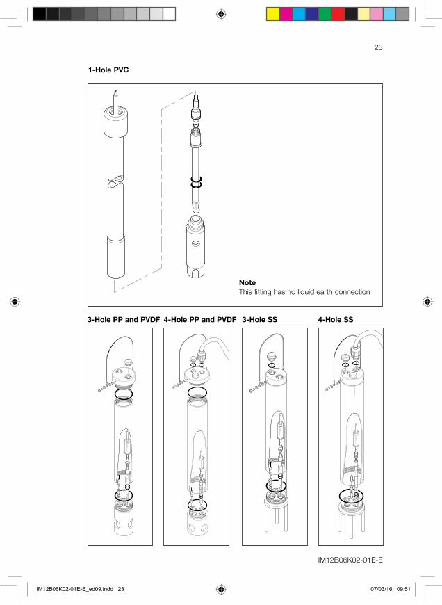
23
1-Hole PVC
NoteThis fitting has no liquid earth connection
3-Hole PP and PVDF 4-Hole PP and PVDF 3-Hole SS 4-Hole SS
IM12B06K02-01E-E_ed09.indd 23 07/03/16 09:51
IM 12B06K02-01E-ESubject to change without notice Printed in The Netherlands, 09-1603 (A) ICopyright ©
IM 12X0X0-E-ESubject to change without notice Printed in The Netherlands, 00-000 (A) ICopyright ©
Yokogawa has an extensive sales and distribution network. Please refer to the European website (www.yokogawa.com/eu) to contact your nearest representative.
YOKOGAWA EUROPE BVEuroweg 23825 HD AMERSFOORTThe Netherlandswww.yokogawa.com/eu
YOKOGAWA ELECTRIC CORPORATIONWorld Headquarters9-32, Nakacho 2-chome, Musashino-shiTokyo 180-8750Japanwww.yokogawa.com
YOKOGAWA CORPORATION OF AMERICA2 Dart RoadNewnan GA 30265USAwww.yokogawa.com/us
YOKOGAWA ELECTRIC ASIA Pte. LTD.5 Bedok South RoadSingapore 469270Singaporewww.yokogawa.com/sg
YOKOGAWA CHINA CO. LTD.3F Tower D Cartelo Crocodile BuildingNo.568 West Tianshan Road Changing DistrictShanghai, Chinawww.yokogawa.com/cn
YOKOGAWA MIDDLE EAST B.S.C.(c)P.O. Box 10070, ManamaBuilding 577, Road 2516, Busaiteen 225Muharraq, Bahrainwww.yokogawa.com/bh
IM12B06K02-01E-E_ed09.indd 24 07/03/16 09:51