instruction manual - · pdf file7.4. unique mixprooflp valve - service kits -4"and...
TRANSCRIPT
2314-0005
ESE02021-EN2 2015-04
Original manual
Instruction Manual
Unique Sanitary Mixproof LP and LP-F Valve

Table of contents
The information herein is correct at the time of issue but may be subject to change without prior notice
1. EC Declaration of Conformity .. . . . . . . . . . . . . . . . . . . . . . . . . . . . . . . . . . . . . . . . . . . . . . . . . . . . . . . . . . . . . . . . . . . . . . 4
2. Safety ... . . . . . . . . . . . . . . . . . . . . . . . . . . . . . . . . . . . . . . . . . . . . . . . . . . . . . . . . . . . . . . . . . . . . . . . . . . . . . . . . . . . . . . . . . . . . . . . . . 52.1. Important information .. . . . . . . . . . . . . . . . . . . . . . . . . . . . . . . . . . . . . . . . . . . . . . . . . . . . . . . . . . . . . . . . . . . . . . . . . . . . 52.2. Warning signs .. .. . . . . . . . . . . . . . . . . . . . . . . . . . . . . . . . . . . . . . . . . . . . . . . . . . . . . . . . . . . . . . . . . . . . . . . . . . . . . . . . . . 52.3. Safety precautions .. . .. . . . . . . . . . . . . . . . . . . . . . . . . . . . . . . . . . . . . . . . . . . . . . . . . . . . . . . . . . . . . . . . . . . . . . . . . . . . 6
3. Installation .. . . . . . . . . . . . . . . . . . . . . . . . . . . . . . . . . . . . . . . . . . . . . . . . . . . . . . . . . . . . . . . . . . . . . . . . . . . . . . . . . . . . . . . . . . . . . 73.1. Unpacking/intermediate storage .. . .. . . . . . . . . . . . . . . . . . . . . . . . . . . . . . . . . . . . . . . . . . . . . . . . . . . . . . . . . . . . 73.2. General information .. .. . . . . . . . . . . . . . . . . . . . . . . . . . . . . . . . . . . . . . . . . . . . . . . . . . . . . . . . . . . . . . . . . . . . . . . . . . . . 113.3. Welding .. . . . . . . . . . . . . . . . . . . . . . . . . . . . . . . . . . . . . . . . . . . . . . . . . . . . . . . . . . . . . . . . . . . . . . . . . . . . . . . . . . . . . . . . . . . 12
4. Operation ... . . . . . . . . . . . . . . . . . . . . . . . . . . . . . . . . . . . . . . . . . . . . . . . . . . . . . . . . . . . . . . . . . . . . . . . . . . . . . . . . . . . . . . . . . . . . 154.1. Operation .. .. . . . . . . . . . . . . . . . . . . . . . . . . . . . . . . . . . . . . . . . . . . . . . . . . . . . . . . . . . . . . . . . . . . . . . . . . . . . . . . . . . . . . . . 154.2. Troubleshooting and repair . . . . . . . . . . . . . . . . . . . . . . . . . . . . . . . . . . . . . . . . . . . . . . . . . . . . . . . . . . . . . . . . . . . . . . 164.3. Recommended cleaning ... . . . . . . . . . . . . . . . . . . . . . . . . . . . . . . . . . . . . . . . . . . . . . . . . . . . . . . . . . . . . . . . . . . . . . . 17
5. Maintenance .. . .. . . . . . . . . . . . . . . . . . . . . . . . . . . . . . . . . . . . . . . . . . . . . . . . . . . . . . . . . . . . . . . . . . . . . . . . . . . . . . . . . . . . . . . 215.1. General maintenance .. . . . . . . . . . . . . . . . . . . . . . . . . . . . . . . . . . . . . . . . . . . . . . . . . . . . . . . . . . . . . . . . . . . . . . . . . . . . 215.2. Dismantling of valve ... . . . . . . . . . . . . . . . . . . . . . . . . . . . . . . . . . . . . . . . . . . . . . . . . . . . . . . . . . . . . . . . . . . . . . . . . . . . 255.3. Lower plug, replacement of radial seal . .. . . . . . . . . . . . . . . . . . . . . . . . . . . . . . . . . . . . . . . . . . . . . . . . . . . . . . . 295.4. Upper plug, replacement of axial seal . . . . . . . . . . . . . . . . . . . . . . . . . . . . . . . . . . . . . . . . . . . . . . . . . . . . . . . . . . 315.5. Valve assembly . .. . . . . . . . . . . . . . . . . . . . . . . . . . . . . . . . . . . . . . . . . . . . . . . . . . . . . . . . . . . . . . . . . . . . . . . . . . . . . . . . . . 335.6. Dismantling of actuator - 4” . . . . . . . . . . . . . . . . . . . . . . . . . . . . . . . . . . . . . . . . . . . . . . . . . . . . . . . . . . . . . . . . . . . . . . 375.7. Assembly of actuator - 4” .. . . . . . . . . . . . . . . . . . . . . . . . . . . . . . . . . . . . . . . . . . . . . . . . . . . . . . . . . . . . . . . . . . . . . . . 395.8. Dismantling of actuator - 6” . . . . . . . . . . . . . . . . . . . . . . . . . . . . . . . . . . . . . . . . . . . . . . . . . . . . . . . . . . . . . . . . . . . . . . 415.9. Assembly of actuator - 6” .. . . . . . . . . . . . . . . . . . . . . . . . . . . . . . . . . . . . . . . . . . . . . . . . . . . . . . . . . . . . . . . . . . . . . . . 43
6. Technical data ... . . . . . . . . . . . . . . . . . . . . . . . . . . . . . . . . . . . . . . . . . . . . . . . . . . . . . . . . . . . . . . . . . . . . . . . . . . . . . . . . . . . . . . 456.1. Technical data .. .. . . . . . . . . . . . . . . . . . . . . . . . . . . . . . . . . . . . . . . . . . . . . . . . . . . . . . . . . . . . . . . . . . . . . . . . . . . . . . . . . . 45
7. Parts list and service kits . . . . . . . . . . . . . . . . . . . . . . . . . . . . . . . . . . . . . . . . . . . . . . . . . . . . . . . . . . . . . . . . . . . . . . . . . . . . 477.1. Unique Mixproof LP Valve - wear parts 4" and 6" .. . . . . . . . . . . . . . . . . . . . . . . . . . . . . . . . . . . . . . . . . . . . 477.2. Unique Mixproof LP Valve - parts - 4” . . .. . . . . . . . . . . . . . . . . . . . . . . . . . . . . . . . . . . . . . . . . . . . . . . . . . . . . . . 497.3. Unique Mixproof LP Valve - parts - 6” . . .. . . . . . . . . . . . . . . . . . . . . . . . . . . . . . . . . . . . . . . . . . . . . . . . . . . . . . . 527.4. Unique Mixproof LP Valve - service kits - 4" and 6" .. . . . . . . . . . . . . . . . . . . . . . . . . . . . . . . . . . . . . . . . . . 547.5. Unique Mixproof LP-F Valve - wear parts 4" and 6" .. . . . . . . . . . . . . . . . . . . . . . . . . . . . . . . . . . . . . . . . . . 567.6. Unique Mixproof LP-F Valve - parts - 4” .. . . . . . . . . . . . . . . . . . . . . . . . . . . . . . . . . . . . . . . . . . . . . . . . . . . . . . . 587.7. Unique Mixproof LP-F Valve - parts - 6” .. . . . . . . . . . . . . . . . . . . . . . . . . . . . . . . . . . . . . . . . . . . . . . . . . . . . . . . 607.8. Unique Mixproof LP-F Valve - service kits - 4" and 6" ... . . . . . . . . . . . . . . . . . . . . . . . . . . . . . . . . . . . . . 62
3

1 EC Declaration of Conformity
The Designated Company
Alfa Laval Kolding A/SCompany Name
Albuen 31, DK-6000 Kolding, DenmarkAddress
+45 79 32 22 00Phone No.
hereby declare that
ValveDesignation
Unique LP, Unique LP-F
Type
From serial number 1181354 - 9999999
is in conformity with the following directive with amendments:
- Machinery Directive 2006/42/EC- Regulation (EC) No 1935/2004- The valve is in compliance with the Pressure Equipment Directive 97/23/EC and was subjected to the following assessment
procedure Module A. Diameters ≥ DN125 may not be used for fluids group 1.
The person authorised to compile the technical file is the signer of this document
QHSE Manager, Quality, Health and safety & Environment Annie DahlTitle Name
Kolding 2013-03-07Place Date Signature
4

2 Safety
Unsafe practices and other important information are emphasised in this manual.Warnings are emphasised by means of special signs.
2.1 Important information
Always read the manual before using the valve!
WARNINGIndicates that special procedures must be followed to avoid serious personal injury.
CAUTIONIndicates that special procedures must be followed to avoid damage to the valve.
NOTEIndicates important information to simplify or clarify procedures.
2.2 Warning signs
General warning:
Caustic agents:
5
2 Safety
All warnings in the manual are summarised on this page.Pay special attention to the instructions below so that serious personal injury and/or damage to the valve are avoided.
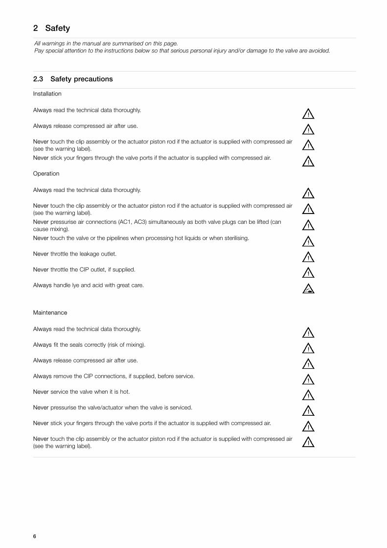
2.3 Safety precautions
Installation
Always read the technical data thoroughly.
Always release compressed air after use.
Never touch the clip assembly or the actuator piston rod if the actuator is supplied with compressed air(see the warning label).
Never stick your fingers through the valve ports if the actuator is supplied with compressed air.
Operation
Always read the technical data thoroughly.
Never touch the clip assembly or the actuator piston rod if the actuator is supplied with compressed air(see the warning label).
Never pressurise air connections (AC1, AC3) simultaneously as both valve plugs can be lifted (cancause mixing).
Never touch the valve or the pipelines when processing hot liquids or when sterilising.
Never throttle the leakage outlet.
Never throttle the CIP outlet, if supplied.
Always handle lye and acid with great care.
Maintenance
Always read the technical data thoroughly.
Always fit the seals correctly (risk of mixing).
Always release compressed air after use.
Always remove the CIP connections, if supplied, before service.
Never service the valve when it is hot.
Never pressurise the valve/actuator when the valve is serviced.
Never stick your fingers through the valve ports if the actuator is supplied with compressed air.
Never touch the clip assembly or the actuator piston rod if the actuator is supplied with compressed air(see the warning label).
6

3 Installation
The instruction manual is part of the delivery.Study the instructions carefully.Fit the warning label supplied on the valve after installation so that it is clearly visible.
3.1 Unpacking/intermediate storage
Step 1CAUTIONAlfa Laval cannot be held responsible for incorrect unpacking.Check the delivery for:1. Complete valve.2. Delivery note.3. Warning label.
Step 2Remove upper support.
2314-0006
Step 3Lift out the valve.NOTE!Please note weight of valve as printed on box.
2314-0007
7

3 Installation
The instruction manual is part of the delivery.Study the instructions carefully.Fit the warning label supplied on the valve after installation so that it is clearly visible.
Step 4Remove possible packing materials from the valve ports.
2314-0008
Step 5Inspect the valve for visible transport damage.
Inspection!
2314-0009
Step 6Avoid damaging the air connections, the leakage outlet, the valveports and the CIP connections, if supplied.
Caution!
2314-0009
8

3 Installation
The instruction manual is part of the delivery.Study the instructions carefully.Fit the warning label supplied on the valve after installation so that it is clearly visible.
Step 7Disassemble according to illustrations 1 to 6(please also see 5.2 Dismantling of valve).1. Supply compressed air.2. Remove upper clamp.3. Release compressed air.4. Lift out actuator with plugs.5. Remove lower clamp.6. Take away lower sealing element.
on / off
2314-0010
1
2
5
4
3
6
9
3 Installation
The instruction manual is part of the delivery.Study the instructions carefully.Fit the warning label supplied on the valve after installation so that it is clearly visible.
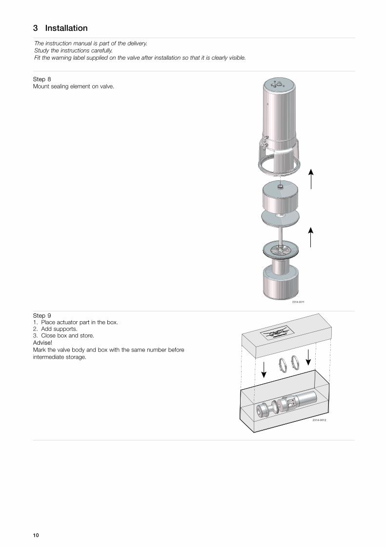
Step 8Mount sealing element on valve.
2314-0011
Step 91. Place actuator part in the box.2. Add supports.3. Close box and store.Advise!Mark the valve body and box with the same number beforeintermediate storage.
2314-0012
10

3 Installation
Study the instructions carefully and pay special attention to the warnings!The valve has ends for welding as standard but can also be supplied with fittings.
3.2 General information
Step 1
Always read the technical data thoroughly.
Always release compressed air after use.
Never touch the clip assembly or the actuator piston rod if theactuator is supplied with compressed air (see the warning label).
CAUTIONFit the supplied warning label on the valve so that itis clearly visible.
CAUTIONAlfa Laval cannot be held responsible for incorrectinstallation.
NOTEAlways install the valve vertically.
NOTEThe leakage outlet must be turned downwards!
Step 2Avoid stresses to the valve as this can result in deformation ofthe sealing area and malfunction of the valve (leakage or faultyindication).Pay special attention to:- Vibrations.- Thermal expansion of the tubes.- Excessive welding.- Overloading of the pipelines.
Risk of damage!
2314-0013
!
Step 3Fittings: Ensure that the connections are tight.
Remember seal rings!
2314-0014
Step 4Air connection: R 1/8” (BSP).1: Cleaning of upper seat.2: Open valve.3: Cleaning of lower seat.
2314-0015
AC1AC2
AC3
11
3 Installation
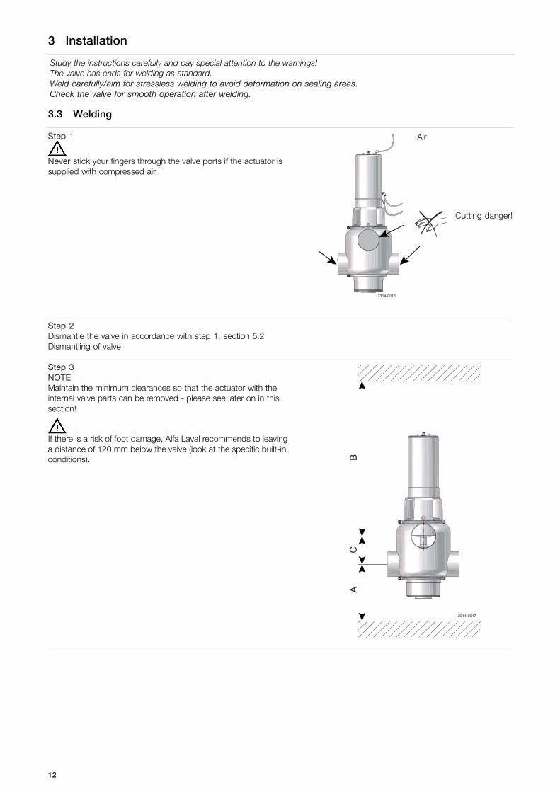
Study the instructions carefully and pay special attention to the warnings!The valve has ends for welding as standard.Weld carefully/aim for stressless welding to avoid deformation on sealing areas.Check the valve for smooth operation after welding.
3.3 Welding
Step 1
Never stick your fingers through the valve ports if the actuator issupplied with compressed air.
Air
Cutting danger!
2314-0016
Step 2Dismantle the valve in accordance with step 1, section 5.2Dismantling of valve.
Step 3NOTEMaintain the minimum clearances so that the actuator with theinternal valve parts can be removed - please see later on in thissection!
If there is a risk of foot damage, Alfa Laval recommends to leavinga distance of 120 mm below the valve (look at the specific built-inconditions). B
CA
2314-0017
12

3 Installation
Study the instructions carefully and pay special attention to the warnings!The valve has ends for welding as standard.Weld carefully/aim for stressless welding to avoid deformation on sealing areas.Check the valve for smooth operation after welding.
Step 4WARNINGMake sure to turn the valve body correctly - conical valve seatupwards. Remove label after
installation of valve body
UP
Remove label afterinstallation of valve body
UP
2314-0018
UP Remove label afterinstallation of valve body
Step 5Assemble the valve in accordance with section 5.5 Valve assemblyafter welding.Pay special attention to the warnings!
Step 6Pre-use check:1. Supply compressed air to AC1, AC2 and AC3 one by one.2. Operate the valve several times to ensure that it runs smoothly.Pay special attention to the warnings!
Operate!
AC1
AC2
AC3
2314-0019
13
3 Installation
Study the instructions carefully and pay special attention to the warnings!The valve has ends for welding as standard.Weld carefully/aim for stressless welding to avoid deformation on sealing areas.Check the valve for smooth operation after welding.
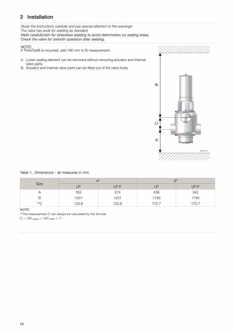
NOTE!If ThinkTop® is mounted, add 180 mm to B measurement.
A. Lower sealing element can be removed without removing actuator and internalvalve parts.
B. Actuator and internal valve parts can be lifted out of the valve body.
BC
A2314-0017
Table 1. Dimensions - all measures in mm
4" 6”Size
LP LP-F LP LP-F
A 352 274 436 342
B 1201 1201 1193 1193
**C 123.6 123.6 172.7 172.7
NOTE!**The measurement C can always be calculated by the formulaC = ½ID-upper + ½ID-lower + 1".
14

4 Operation
The valve is adjusted and tested before delivery.Study the instructions carefully and pay special attention to the warnings!Pay attention to possible faults.The items refer to the parts list and service kits section.
4.1 Operation
Step 1
Always read the technical data thoroughly.
Always release compressed air after use.
Never touch the clip assembly or the actuator piston rod if the actuator is supplied with compressed air (see the warning label).
Never pressurise air connections (AC1, AC3) simultaneously as both valve plugs can be lifted (can cause mixing).
CAUTIONAlfa Laval cannot be held responsible for incorrect operation.
Step 2
Never touch the valve or the pipelines when processing hot liquidsor when sterilising.
Burning danger!
2314-0020
15
4 Operation
The valve is adjusted and tested before delivery.Study the instructions carefully and pay special attention to the warnings!Pay attention to possible faults.The items refer to the parts list and service kits section.
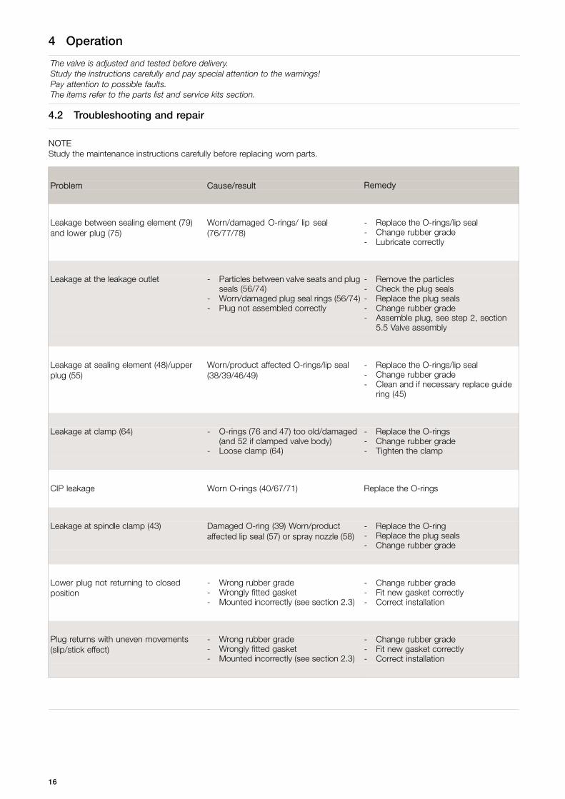
4.2 Troubleshooting and repair
NOTEStudy the maintenance instructions carefully before replacing worn parts.
Problem Cause/result Remedy
Leakage between sealing element (79)and lower plug (75)
Worn/damaged O-rings/ lip seal(76/77/78)
- Replace the O-rings/lip seal- Change rubber grade- Lubricate correctly
Leakage at the leakage outlet - Particles between valve seats and plugseals (56/74)
- Worn/damaged plug seal rings (56/74)- Plug not assembled correctly
- Remove the particles- Check the plug seals- Replace the plug seals- Change rubber grade- Assemble plug, see step 2, section
5.5 Valve assembly
Leakage at sealing element (48)/upperplug (55)
Worn/product affected O-rings/lip seal(38/39/46/49)
- Replace the O-rings/lip seal- Change rubber grade- Clean and if necessary replace guide
ring (45)
Leakage at clamp (64) - O-rings (76 and 47) too old/damaged(and 52 if clamped valve body)
- Loose clamp (64)
- Replace the O-rings- Change rubber grade- Tighten the clamp
CIP leakage Worn O-rings (40/67/71) Replace the O-rings
Leakage at spindle clamp (43) Damaged O-ring (39) Worn/productaffected lip seal (57) or spray nozzle (58)
- Replace the O-ring- Replace the plug seals- Change rubber grade
Lower plug not returning to closedposition
- Wrong rubber grade- Wrongly fitted gasket- Mounted incorrectly (see section 2.3)
- Change rubber grade- Fit new gasket correctly- Correct installation
Plug returns with uneven movements(slip/stick effect)
- Wrong rubber grade- Wrongly fitted gasket- Mounted incorrectly (see section 2.3)
- Change rubber grade- Fit new gasket correctly- Correct installation
16

4 Operation
The valve is designed for cleaning in place (CIP).Study the instructions carefully and pay special attention to the warnings!NaOH = Caustic Soda. HNO3 = Nitric acid.Internal leakage in the valve is externally visible by means of the leakage outlet.
4.3 Recommended cleaning
Step 1
Never touch the valve or the pipelines when sterilising.
Caustic danger!
Always use rubber gloves! Always use protectivegoggles!
Step 2
Never touch the valve or the pipelines when sterilising. Burning danger!
2314-0020
17

4 Operation
The valve is designed for cleaning in place (CIP).Study the instructions carefully and pay special attention to the warnings!NaOH = Caustic Soda. HNO3 = Nitric acid.Internal leakage in the valve is externally visible by means of the leakage outlet.
Step 3
Never throttle the leakage outlet.
Never throttle the CIP outlet, if supplied.(Risk of mixing due to overpressure).
2314-0021
Leakage/CIP out
Step 4Examples of cleaning agents:Use clean water, free from chlorides.
1. 1% by weight NaOH at 70o C 2. 0.5% by weight HNO3 at 70o C
1 kgNaOH
+ 100 l water = Cleaning agent. 0.7 l53% HNO3
+ 100 l water = Cleaning agent.
=2.2 l33%NaOH
+ 100 l water Cleaning agent.
Step 51. Avoid excessive concentration of the cleaning agent
=> Dose gradually!2. Adjust the cleaning flow to the process.
Milk sterilisation/viscous liquids=> Increase the cleaning flow!
Step 6Advisory seat lift cleaning periods:Cleaning periods of 3-6 seconds per CIP sequence.
Product Periods
Milk 1-2
Yoghurt 3-5
Beer 2-5
Cold wort 5-10
18
4 Operation
The valve is designed for cleaning in place (CIP).Study the instructions carefully and pay special attention to the warnings!NaOH = Caustic Soda. HNO3 = Nitric acid.Internal leakage in the valve is externally visible by means of the leakage outlet.
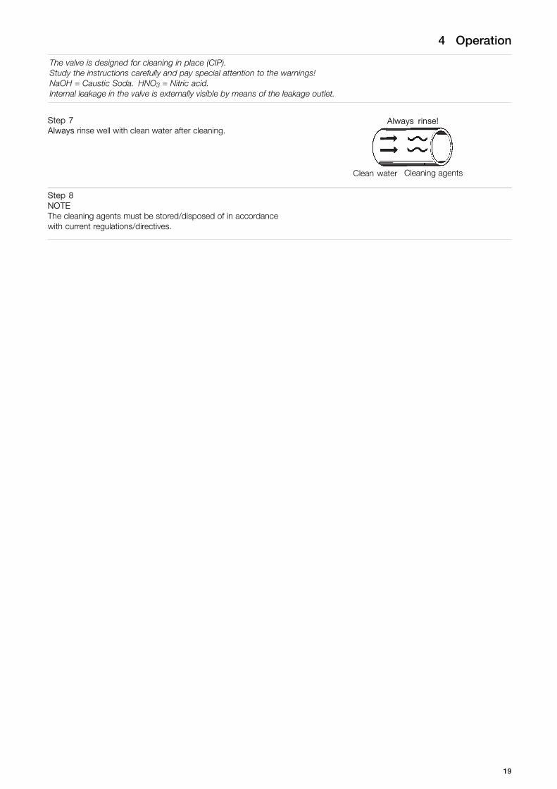
Step 7Always rinse well with clean water after cleaning.
Always rinse!
Clean water Cleaning agents
Step 8NOTEThe cleaning agents must be stored/disposed of in accordancewith current regulations/directives.
19
4 Operation
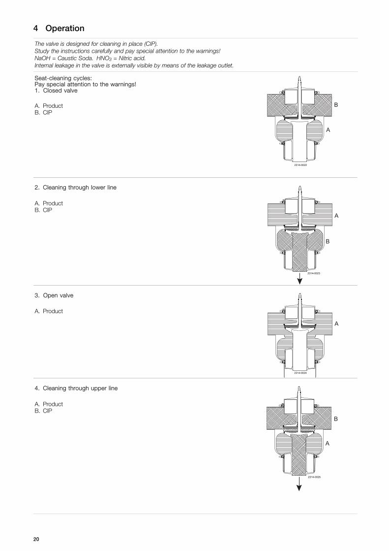
The valve is designed for cleaning in place (CIP).Study the instructions carefully and pay special attention to the warnings!NaOH = Caustic Soda. HNO3 = Nitric acid.Internal leakage in the valve is externally visible by means of the leakage outlet.
Seat-cleaning cycles:Pay special attention to the warnings!1. Closed valve
A. ProductB. CIP
2314-0022
A
B
2. Cleaning through lower line
A. ProductB. CIP
2314-0023
A
B
3. Open valve
A. Product
2314-0024
A
4. Cleaning through upper line
A. ProductB. CIP
2314-0025
B
A
20

5 Maintenance
Maintain the valve/actuator regularly. Study the instructions carefully and pay special attention to the warnings!Always keep spare rubber seals and guide rings in stock. The items refer to the parts list and service kits section.The valve is designed so that internal leakages do not result in the products becoming mixed.Internal leakage in the valve is externally visible. Check the valve for smooth operation after service.
5.1 General maintenance
Step 1
Always read the technical data thoroughly.
Always fit the seals correctly (risk of mixing).
Always release compressed air after use.
Always remove the CIP connections, if supplied, before service.
NOTEAll scrap must be stored/disposed off in accordance with current regulations/directives.
Step 2
Never service the valve when it is hot.
Never service the valve with valve/actuator under pressure.
Burning danger!
Atmosphericpressure required!
2314-0026
Step 3
Never stick your fingers through the valve ports if the actuator issupplied with compressed air.
Air
Cuttingdanger!
2314-0016
21

5 Maintenance
Maintain the valve/actuator regularly. Study the instructions carefully and pay special attention to the warnings!Always keep spare rubber seals and guide rings in stock. The items refer to the parts list and service kits section.The valve is designed so that internal leakages do not result in the products becoming mixed.Internal leakage in the valve is externally visible. Check the valve for smooth operation after service.
Step 4
Never touch the clip assembly or the actuator piston rod if theactuator is supplied with compressed air (see the warning label).
Air
Moving parts
2314-0027
22

5 Maintenance
Maintain the valve/actuator regularly. Study the instructions carefully and pay special attention to the warnings!Always keep spare rubber seals and guide rings in stock. The items refer to the parts list and service kits section.The valve is designed so that internal leakages do not result in the products becoming mixed.Internal leakage in the valve is externally visible. Check the valve for smooth operation after service.
Recommended spare parts: Service kits
Order service kits from the service kits section
Ordering spare parts: Contact the Sales Department.
Valve rubber seals Valve plug seals Valve guide rings
Preventive maintenance Replace after 12 months(*) Replace after 12 months(*) Replace when required
Maintenance after leakage(leakage normally starts slowly)
Replace after productioncycle
Replace after productioncycle
Planned maintenance - Regular inspection forleakage and smoothoperation
- Keep a record of the valve- Use the statistics for
inspection planning
- Regular inspection forleakage and smoothoperation
- Keep a record of the valve- Use the statistics for
inspection planning
Replace when required
Lubrication When assemblingKlüber Paraliq GTE 703 orsimilar USDA H1 approvedoil/grease (**) (suitable forEPDM)
When assemblingKlüber Paraliq GTE 703 orsimilar USDA H1 approvedoil/grease (**) (suitable forEPDM)
None
NOTE!Lubricate thread in valve plug parts with Klüber Paste UH1 84-201 or similar.(*) Depending on working conditions! Please contact Alfa Laval.(**) All products wetted seals.
Repairing of actuator:- The actuator is maintenance-free but repairable.- If repair is required, replacing all actuator rubber seals is recommended.- Lubricate seals with Klüberplex BE31.- To avoid possible black marks on pos. 1 and 29, Alfa Laval recommends Klüber Paraliq GTE703 (white) for these two
positions.
23

5 Maintenance
Maintain the valve/actuator regularly. Study the instructions carefully and pay special attention to the warnings!Always keep spare rubber seals and guide rings in stock. The items refer to the parts list and service kits section.The valve is designed so that internal leakages do not result in the products becoming mixed.Internal leakage in the valve is externally visible. Check the valve for smooth operation after service.
Pre-use check1. Supply compressed air to AC1, AC2
and AC3 one by one.2. Operate the valve several times to
ensure that it operates smoothly.Pay special attention to the warnings!
Operate!
AC1
AC2
AC3
2314-0019
24

5 Maintenance
Study the instructions carefully.The items refer to the parts list and service kits section.Handle scrap correctly.Replace seals if necessary.
5.2 Dismantling of valve
(NOTE: LP-F IS SHOWN!)
Step 1Disassemble valve acc. to illustrations (1 to 6).1. Supply compressed air to A2.2. Loosen and remove upper clamp (64).3. Release compressed air.4. Lift out the actuator together with the internal valve parts from
valve body (50).5. Loosen and remove lower clamp (64).6. Remove lower sealing element (79).
NOTERelease compressed air.
2314-0010
1
2
5
4
3
6
25
5 Maintenance
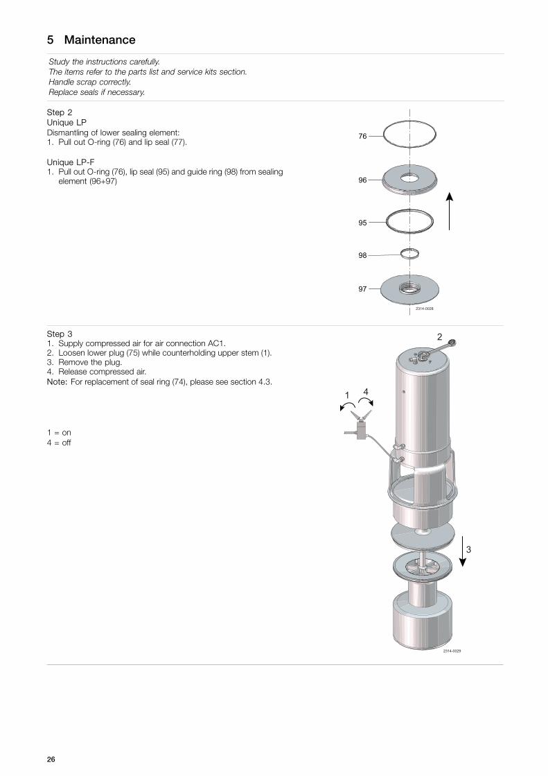
Study the instructions carefully.The items refer to the parts list and service kits section.Handle scrap correctly.Replace seals if necessary.
Step 2Unique LPDismantling of lower sealing element:1. Pull out O-ring (76) and lip seal (77).
Unique LP-F1. Pull out O-ring (76), lip seal (95) and guide ring (98) from sealing
element (96+97)
2314-0028
98
97
95
96
76
Step 31. Supply compressed air for air connection AC1.2. Loosen lower plug (75) while counterholding upper stem (1).3. Remove the plug.4. Release compressed air.Note: For replacement of seal ring (74), please see section 4.3.
1 = on4 = off
1
3
4
2
2314-0029
26

5 Maintenance
Study the instructions carefully.The items refer to the parts list and service kits section.Handle scrap correctly.Replace seals if necessary.
Step 4Remove coupling system and upper plug according to illustrations(1 to 4).1. Unscrew plug (15)2. Pull up lock (44) over piston rod (29).3. Pull away clamps (43) from spindle liner (42).4. Pull out upper plug (55). Make sure spindle liner is free of both
piston rod and upper plug.
2314-0030
29
(3)
43
42
(3)15
(1)
(4)55
44
(2)
27

5 Maintenance
Study the instructions carefully.The items refer to the parts list and service kits section.Handle scrap correctly.Replace seals if necessary.
Step 51. Remove upper sealing element (48) from upper plug (55).2. Pull out O-ring (47) and lip seal (49) from upper sealing element.
55
47
49
48
2314-0031
Step 6Remove lip seal (57) and guide ring (54). For removal andreplacement of seal ring (56), please see section 5.3 Lower plug,replacement of radial seal.
57
54
56
55
2314-0032
28

5 Maintenance
Study the instructions carefully.The items refer to the parts list and service kits section.Handle scrap correctly.
5.3 Lower plug, replacement of radial seal
Step 1Cut and remove old seal ring (74) using a knife, screwdriver orsimilar. Be careful not to scratch the plug.
2314-0033
Step 2Pre-mount seal ring as shown on drawing.Rotate along circumference to fix gasket as shown in the picture.Carefully lubricate sealings with suitable soap or lubricant, beforepre-mounting.
2314-0034
29
5 Maintenance
Study the instructions carefully.The items refer to the parts list and service kits section.Handle scrap correctly.
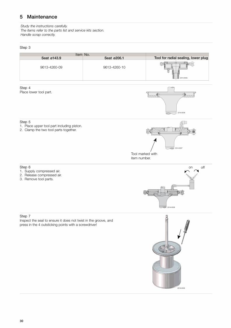
Step 3
Item No.Seat ø143.9 Seat ø206.1 Tool for radial sealing, lower plug
9613-4260-09 9613-4260-10
2314-0035
Step 4Place lower tool part.
2314-0036
Step 51. Place upper tool part including piston.2. Clamp the two tool parts together.
2314-0037
Tool marked withitem number.
Step 61. Supply compressed air.2. Release compressed air.3. Remove tool parts.
on off
2314-0038
Step 7Inspect the seal to ensure it does not twist in the groove, andpress in the 4 outsticking points with a screwdriver!
2314-0039
30

5 Maintenance
Study the instructions carefully.The items refer to the parts list and service kits section.Handle scrap correctly
5.4 Upper plug, replacement of axial seal
Step 1Remove old seal ring (56) using a knife, screwdriver or similar. Becareful not to scratch the plug.
2314-0040
Step 2Pre-mount seal ring as shown on drawing.
A
C
B
2314-0056
A = Flat side of the sealingB = Balanced plugC = Do not lubricate behind the sealing
2314-0041
Carefully lubricate sealings with suitable soap or lubricant, before pre-mounting.
Step 3
Item No.Seat ø143.9 Seat ø206.1 Tool for axial sealing, upper plug
9613-0505-07 9613-0505-10
2314-0042
Step 4Place tool part 1.
2314-0043
Step 51. Place tool part 2 including piston.2. Clamp the two tool parts together.
Tooling marked with item number
2314-0044
31

5 Maintenance
Study the instructions carefully.The items refer to the parts list and service kits section.Handle scrap correctly
Step 61. Supply compressed air.2. Release compressed air.3. Rotate the tool 45° in relation to the plug.4. Supply compressed air.5. Release compressed air and remove tool.
on off
2314-0045
Step 71. Inspect the seal.2. Release air at 3 different positions of the circumference.
2314-0046
32

5 Maintenance
Study the instructions carefully.The items refer to the parts list and service kits section.Handle scrap correctly.Replace seals if necessary.
5.5 Valve assembly
Step 11. Fit O-ring (47) (do not twist), and lip seal (49) in upper sealing
element (48) (Lubricate with Klüber Paralique GT 703).NOTE: The O-ring should be gently pressed into the groove
2. Fit upper sealing element in intermediate piece (37).
47
37
49
48
2314-0047
45
Step 21. Place lip seal (57) and guide ring (54) in upper plug and the
O-ring (38) in the lower plug.2. Press lower plug (75) rapidly into upper plug (55) through the
lip seal.Note: Do not damage the lips when lower plug (75) with O-ring(38) passes the lip seal.
57
38
75
55
2314-0048
54
33

5 Maintenance
Study the instructions carefully.The items refer to the parts list and service kits section.Handle scrap correctly.Replace seals if necessary.
Step 3Place coupling system and upper plug according to illustrations.1. Push lock (44) up over piston rod (29).2. Place spindle liner (42) on piston rod. Fit upper plug (55).3. Mount clamps (43) on spindle liner (42).4. Fit lock (44).5. Fit plug (15).
2314-0049
(5)
29(1)
44
(3)
4342
(3)(2)
15
55
(4)
(2)
43
34
5 Maintenance
Study the instructions carefully.The items refer to the parts list and service kits section.Handle scrap correctly.Replace seals if necessary.
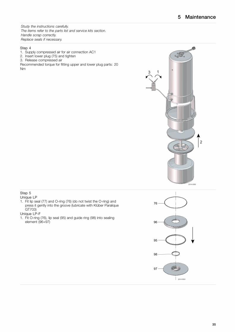
Step 41. Supply compressed air for air connection AC12. Insert lower plug (75) and tighten3. Release compressed airRecommended torque for fitting upper and lower plug parts: 20Nm
2
1
2314-0050
3
Step 5Unique LP1. Fit lip seal (77) and O-ring (76) (do not twist the O-ring) and
press it gently into the groove (lubricate with Klüber ParaliqueGT703)
Unique LP-F1. Fit O-ring (76), lip seal (95) and guide ring (98) into sealing
element (96+97)
2314-0051
98
97
95
96
76
35

5 Maintenance
Study the instructions carefully.The items refer to the parts list and service kits section.Handle scrap correctly.Replace seals if necessary.
Step 6- Never stick your fingers through the valve ports if the actuator
is supplied with compressed air.- Always supply compressed air, before demounting the valve.1. Fit lower sealing element (79).2. Fit and tighten lower clamp (64).3. Supply compressed air (AC2) and mount the actuator together
with the internal valve parts in valve body (50).4. Fit and tighten upper clamp (64). Greasing of clamp and clamp
nut recommended!(Maximum torque for clamp nut: 10 Nm)
5. Release compressed air.
NOTESupply compressed air before demounting the valve.
on off
2314-0052
3
4
2
3
5
1
36

5 Maintenance
Study the instructions carefully.The items refer to the parts list and service kits section.Handle scrap correctly.Replace seals if necessary.
5.6 Dismantling of actuator - 4”
15
27
13
19
18
17
26
112
11
10
2
4
8
7
9
16
3.1
15
3
3.2
82
37
83/83.1
34
36
25
35
24
23
22
20
21
31
33
30
32
29
28
14
TD 481-015_2
3.3
135136
134
65
121
120
127
133132
125131134
124125122
123
122
126
128129130
37

5 Maintenance
Study the instructions carefully.The items refer to the parts list and service kits section.Handle scrap correctly.Replace seals if necessary.
Step 11. Dismantle the valve in accordance with instructions in section 5.2 Dismantling of valve
Pay special attention to the warnings!2. The actuator is now ready for service. Please see drawing when dismantling according to steps 2 to 6 on this page.
Note! The actuator is maintenance-free but repairable.
Step 21. Place the actuator with intermediate piece in a vice.2. Remove booster cylinder (126) by turning the cylinder.
Turn the cylinder until the lock ring (120) is fully removed though the groove in the cylinder and remove the cylinder.3. Remove the bushing (128) with O-rings (129 & 130).4. Remove the pistons (124 & 132).5. Remove the lock ring (136) and separate the two pistons.
Remove all O-rings and bearings (122, 123, 125, 134, 131 &133)6. Activate main stroke (Air fitting Position 3).7. Remove screw (135) and pull out booster spindle (127).8. Deactivate main stroke and remove actuator from vice.
Step 31. Remove nuts (36) and washers (35).2. Pull out intermediate piece (37) from the actuator.3. Remove cover disk (25).4. Remove retaining ring (24).
Step 41. Remove piston rod (29), bottom (21) and lower piston (30).2. Separate the three parts.3. Remove O-rings (20, 22 and 23) from bottom, O-rings (33 and 31) and guide ring (32) from lower piston as well as O-ring
(28) from piston rod.4. Remove spring assembly (14).
Step 51. Remove inner stem (27), main piston (17) and distance spacer (11). Remove guide ring (18) and O-ring (19)2. Remove spring assembly (10).
Step 61. Unscrew screws (2) (glued!).2. Remove stop (4).3. Remove upper piston (8). Remove O-rings (7 and 9).
Step 71. Remove O-ring (5) and guide ring (6).
38
5 Maintenance
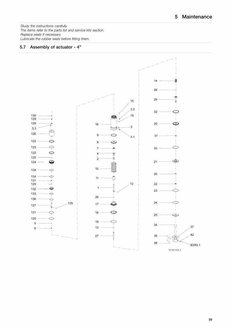
Study the instructions carefully.The items refer to the parts list and service kits section.Replace seals if necessary.Lubricate the rubber seals before fitting them.
5.7 Assembly of actuator - 4”
15
27
13
19
18
17
26
112
11
10
2
4
8
7
9
16
3.1
15
3
3.2
82
37
83/83.1
34
36
25
35
24
23
22
20
21
31
33
30
32
29
28
14
TD 481-015_2
3.3
135136
134
65
121
120
127
133132
125131134
124125122
123
122
126
128129130
39

5 Maintenance
Study the instructions carefully.The items refer to the parts list and service kits section.Replace seals if necessary.Lubricate the rubber seals before fitting them.
Step 1Please see drawing when reassembling according to steps 2 to 5 on this page.Note! The actuator is maintenance-free but repairable.
Step 21. Fit guide ring (6) and O-ring (5).2. Fit O-rings (7 and 9). Place upper piston (8).3. Fit stop (4).4. Tighten screws (2). (Secure with glue)
Step 31. Place spring assembly (10).2. Fit O-ring (19) and guide ring (18). Mount distance spacer (11), main piston (17) and inner stem (27).
Step 41. Fit spring assembly (14).2. Fit O-ring (28) in piston rod, fit O-rings (33 and 31) and guide ring (32) in lower piston and fit O-rings (20, 22 and 23) in bottom.3. Fit piston rod (29), lower piston (30) and bottom (21).4. Mount the three parts.
Step 51. Fit retaining ring (24).2. Fit cover disk (25).3. Mount intermediate piece (37) on actuator.4. Fit and tighten nuts (36) and washers (35).
Step 61. Place the actuator with the intermediate in a vice.2. Activate main stroke (air fitting position 3).3. Mount upper stem (127) and secure it with the screw (135).4. Deactivate main stroke.
Step 71. Mount O-ring and guide ring (133, 125 & 131) on inner piston (132).2. Mount O-ring and guide rings (125, 122, 134 & 123) on piston (124).3. Insert the inner piston in the piston and secure the inner piston with the lock ring (136).4. Mount the pistons onto the upper stem (127).
Step 81. Mount bushing (128) and O-rings (129 & 130) on the top of the cylinder.2. Mount the cylinder onto the cylinder (16). Rotate the cylinder until the pin hole for the lock ring (120) can be seen through
the slot on the side of the cylinder.3. Insert the lock ring (120) in the pin hole and turn the cylinder until the complete lock ring has wandered through the slot.4. Remove the actuator from the vice.
40

5 Maintenance
Study the instructions carefully.The items refer to the parts list and service kits section.Handle scrap correctly.Replace seals if necessary.
5.8 Dismantling of actuator - 6”
27
19
13
18
17
26
1 12
10
11
2
4
7
22
8
9
16
37
6
5
34
15
3
3
36
35
25
23
24
20
3
21
33
31
30
32
29
28
14
2314-0004_1
41

5 Maintenance
Study the instructions carefully.The items refer to the parts list and service kits section.Handle scrap correctly.Replace seals if necessary.
Step 11. Dismantle the valve in accordance with instructions in section 4.2
Pay special attention to the warnings!2. The actuator is now ready for service.
Please see drawing when dismantling according to steps 2 to 6 on this page.Note! The actuator is maintenance-free but repairable.
Step 21. Remove nuts (36) and washers (35).2. Pull out intermediate piece (37) from the actuator.3. Remove cover disk (25).4. Remove retaining ring (24).
Step 31. Remove piston rod (29), bottom (21) and lower piston (30).2. Separate the three parts.3. Remove O-rings (20, 22 and 23) from bottom, O-rings (33 and 31) and guide ring (32) from lower piston as well as O-ring
(28) from piston rod.4. Remove spring assembly (14).
Step 41. Remove inner stem (27), main piston (17) and distance spacer (11). Remove guide ring (18) and O-ring (19).2. Remove spring assembly (10).
Step 51. Unscrew screws (2) (glued!).2. Remove stop (4).3. Remove upper piston (8). Remove O-rings (7 and 9).
Step 6Remove O-ring (5) and guide ring (6).
42

5 Maintenance
Study the instructions carefully.The items refer to the parts list and service kits section.Replace seals if necessary.Lubricate the rubber seals before fitting them.
5.9 Assembly of actuator - 6”
27
19
13
18
17
26
1 12
10
11
2
4
7
22
8
9
16
37
6
5
34
15
3
3
36
35
25
23
24
20
3
21
33
31
30
32
29
28
14
2314-0004_1
43

5 Maintenance
Study the instructions carefully.The items refer to the parts list and service kits section.Replace seals if necessary.Lubricate the rubber seals before fitting them.
Step 1Please see drawing when reassembling according to steps 2 to 5 on this page.Note! The actuator is maintenance-free but repairable.
Step 21. Fit guide ring (6) and O-ring (5).2. Fit O-rings (7 and 9). Place upper piston (8).3. Fit stop (4).4. Tighten screws (2). (Secure with glue)
Step 31. Place spring assembly (10).2. Fit O-ring (19) and guide ring (18). Mount distance spacer (11), main piston (17) and inner stem (27).
Step 41. Fit spring assembly (14).2. Fit O-ring (28) in piston rod, fit O-rings (33 and 31) and guide ring (32) in lower piston and fit O-rings (20, 22 and 23) in bottom.3. Fit piston rod (29), lower piston (30) and bottom (21).4. Mount the three parts.
Step 51. Fit retaining ring (24).2. Fit cover disk (25).3. Mount intermediate piece (37) on actuator.4. Fit and tighten nuts (36) and washers (35).
44

6 Technical data
It is important to observe the technical data during installation, operation and maintenance.Inform personnel about the technical data.
6.1 Technical data
Unique Mixproof LP-F is remote-controlled by means of compressed air.
The valve is a normally closed (NC) valve. It is as standard supplied seat lift, which enables handling of two different productsat the same time, or safe handling of one product while seat-lift cleaning operations are being conducted in the other portionof the valve – all without any risk of cross-contamination.
The 6” valve is as standard also equipped with balanced lower plug to protect against the effects of high pressure and waterhammer.The 4” valve is, in order to accommodate 45mm particles, not supplied with balanced lower plug.
Data
Max. product pressure: 1000 kPa (10 bar)
Min. product pressure: Full vacuum
Temperature range: -5°C to +125°C (depending on rubber quality)
Air pressure: Max. 800 kPa (8 bar)
Products acc. to PED 97/23/ECCategory I, Fluids group 1,DN ≥ 6” Fluids group 2
Unique LP Unique LP-F
OD ODSize
4" 6” 4" 6”
Cv-value Upper Seat-lift [m3/h] 3.2 7.1 3.2 7.1
Cv-value Lower Seat-lift [m3/h]] 2.9 6.0 3.9 8.9
Air consumption Upper Seat-lift [n litre] 0.62 0.62 0.62 0.62
Air consumption Lower Seat-lift [n litre] 0.21 0.21 0.21 0.21
Air consumption Main Movement [n litre] 3.54 3.54 3.54 3.54
Note! * [n litre] = volume at atmospheric pressure.
Formula to estimate CIP flow during seat lift (for liquids with comparable viscosity and density to water):
Q = Kv • √ Δ p
Q = CIP - flow (m3/h).
Kv = Kv value from the above table.
Δ p = CIP pressure (bar).
Cv = 1.163 x Kv gpm
1 bar = 14.5 psi
45

6 Technical data
It is important to observe the technical data during installation, operation and maintenance.Inform personnel about the technical data.
Materials
Product wetted steel parts: Acid-resistant steel AISI 316L.
Other steel parts: Stainless steel AISI 304
Product wetted parts: EPDM, HNBR, NBR or FPM.
Other seals: CIP seals: EPDM.
Actuator seals: NBR.
Surface finish:Internal/external matt (blasted) Ra < 1.6 µmInternal bright (polished) Ra < 0.8 µmInternal/external bright (internal polished) Ra < 0.8 µm
Note! The Ra-values are only for the internal surface.
Weight (kg)
Size 4” 6”
Weight (kg) 64.90 86.20
46

7 Parts list and service kits
It is important to observe the technical data during installation, operation and maintenance.Inform personnel about the technical data.
7.1 Unique Mixproof LP Valve - wear parts 4" and 6"
TD 481-021
.
.
.
.
10
151126
28
29
30
3
31
32333
3738
45
4860,64
49
47
505456
745776
77
27
81
8079
523 1 6 7 489
12
1314
16
18192120
232425
22
3435
3615
42,43,44
75
55
17
2314-0002
8283 83.1
4” 6”
= Sensor kit
= Wear parts
47

7 Parts list and service kits
It is important to observe the technical data during installation, operation and maintenance.Inform personnel about the technical data.
Parts list
Pos. Qty Denomination
38 1 O-ring47 1 O-ring49 1 Lip seal56 1 Seal ring57 1 Lip seal74 1 Seal ring76 1 O-ring77 1 Lip seal
48

7 Parts list and service kits
It is important to observe the technical data during installation, operation and maintenance.Inform personnel about the technical data.
7.2 Unique Mixproof LP Valve - parts - 4”
49
7 Parts list and service kits
It is important to observe the technical data during installation, operation and maintenance.Inform personnel about the technical data.
2314-0003
60
3
135
15
136
134
27
1319
18
17
26
1
1211
10
24
87
43
9
42
15
16
44
3
15
3
635
37
34
36
121120
127
25
35
133
24
132125131134
23
22
124
20
125122123
21
122
76
126
6460
128
31
33
129130
50
30
64
32
29
28
75
14
74
38
57
54
56
55
47
49
48
45
79
81
80
77
= Wear parts
50
7 Parts list and service kits
It is important to observe the technical data during installation, operation and maintenance.Inform personnel about the technical data.
Parts list
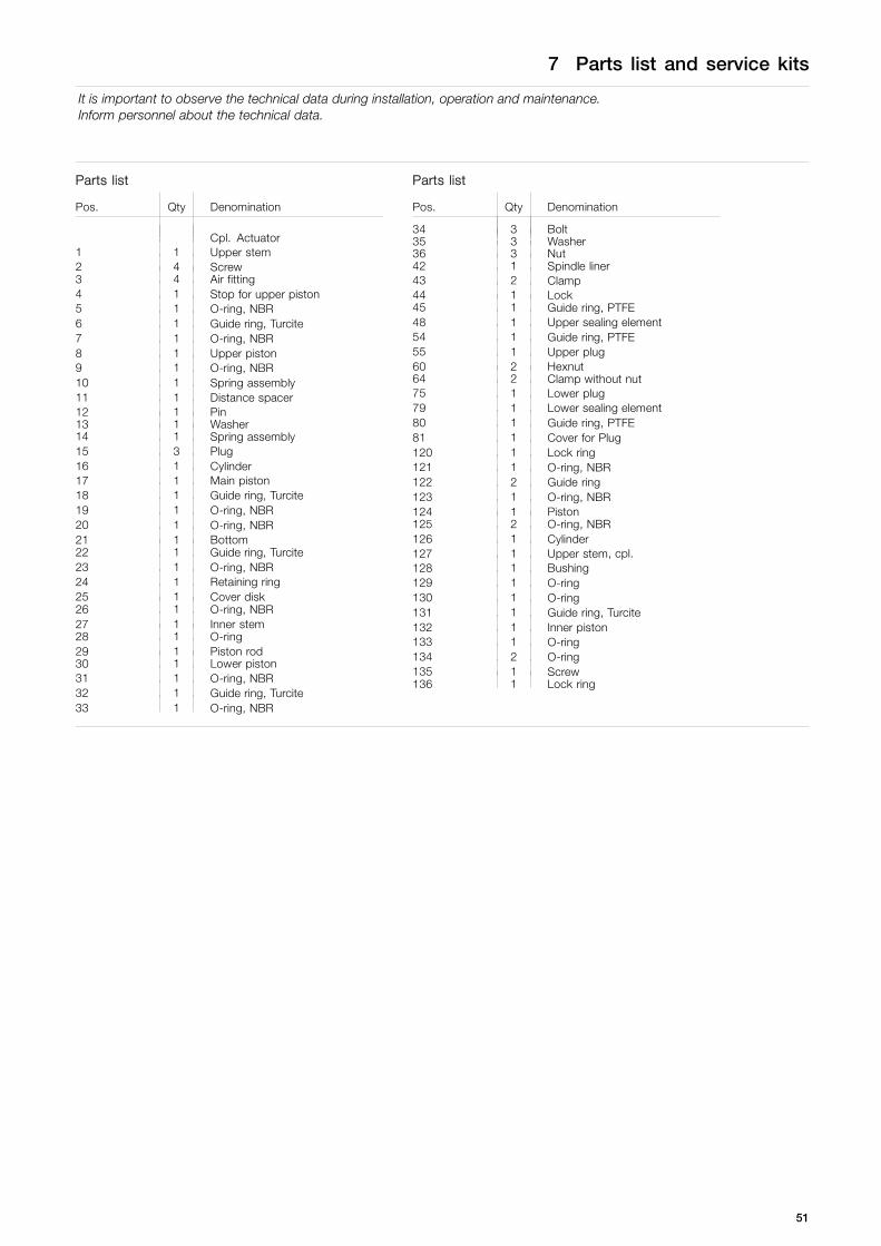
Pos. Qty Denomination
Cpl. Actuator1 1 Upper stem2 4 Screw3 4 Air fitting4 1 Stop for upper piston5 1 O-ring, NBR6 1 Guide ring, Turcite7 1 O-ring, NBR8 1 Upper piston9 1 O-ring, NBR10 1 Spring assembly11 1 Distance spacer12 1 Pin13 1 Washer14 1 Spring assembly15 3 Plug16 1 Cylinder17 1 Main piston18 1 Guide ring, Turcite19 1 O-ring, NBR20 1 O-ring, NBR21 1 Bottom22 1 Guide ring, Turcite23 1 O-ring, NBR24 1 Retaining ring25 1 Cover disk26 1 O-ring, NBR27 1 Inner stem28 1 O-ring29 1 Piston rod30 1 Lower piston31 1 O-ring, NBR32 1 Guide ring, Turcite33 1 O-ring, NBR
Parts list
Pos. Qty Denomination
34 3 Bolt35 3 Washer36 3 Nut42 1 Spindle liner43 2 Clamp44 1 Lock45 1 Guide ring, PTFE48 1 Upper sealing element54 1 Guide ring, PTFE55 1 Upper plug60 2 Hexnut64 2 Clamp without nut75 1 Lower plug79 1 Lower sealing element80 1 Guide ring, PTFE81 1 Cover for Plug120 1 Lock ring121 1 O-ring, NBR122 2 Guide ring123 1 O-ring, NBR124 1 Piston125 2 O-ring, NBR126 1 Cylinder127 1 Upper stem, cpl.128 1 Bushing129 1 O-ring130 1 O-ring131 1 Guide ring, Turcite132 1 Inner piston133 1 O-ring134 2 O-ring135 1 Screw136 1 Lock ring
51

7 Parts list and service kits
It is important to observe the technical data during installation, operation and maintenance.Inform personnel about the technical data.
7.3 Unique Mixproof LP Valve - parts - 6”
27
19
13
18
17
26
1 12
10
11
24
7
22
8
9
43
4215
16
37
65
34
15
3
3
36
35
25
23
64
24
20
3
21
64
60
33
31
30
32
76
29
28
14
50
75
74
38
57
54
56
47
55
49
48
45
44
2314-0004
60
80
79
81
77
= Wear parts
52

7 Parts list and service kits
It is important to observe the technical data during installation, operation and maintenance.Inform personnel about the technical data.
Parts list
Pos. Qty Denomination
Cpl. Actuator1 1 Upper stem2 4 Screw3 3 Air fitting4 1 Stop for upper piston5 1 O-ring, NBR6 1 Guide ring, Turcite7 1 O-ring, NBR8 1 Upper piston9 1 O-ring, NBR10 1 Spring assembly11 1 Distance spacer12 1 Pin13 1 Washer14 1 Spring assembly15 2 Plug16 1 Cylinder17 1 Main piston18 1 Guide ring, Turcite19 1 O-ring, NBR20 1 O-ring, NBR21 1 Bottom22 1 Guide ring, Turcite23 1 O-ring, NBR24 1 Retaining ring25 1 Cover disk26 1 O-ring, NBR27 1 Inner stem28 1 O-ring29 1 Piston rod30 1 Lower piston31 1 O-ring, NBR32 1 Guide ring, Turcite33 1 O-ring, NBR34 3 Bolt35 3 Washer36 3 Nut42 1 Spindle liner43 2 Clamp44 1 Lock45 1 Guide ring, PTFE48 1 Upper sealing element54 1 Guide ring, PTFE55 1 Upper plug60 2 Hexnut64 2 Clamp without nut75 1 Lower plug79 1 Lower sealing element80 1 Guide ring, PTFE81 1 Cover for Plug
53

7 Parts list and service kits
It is important to observe the technical data during installation, operation and maintenance.Inform personnel about the technical data.
7.4 Unique Mixproof LP Valve - service kits - 4" and 6"
TYPE 22-00 TYPE 22-90
TYPE 12-00 TYPE 12-90 TYPE 21-00 TYPE 21-90
TYPE 11-00 TYPE 11-90 TYPE 11-180 TYPE 11-270
TD 449-014_3
Service kits
48
75
79
55
TD 481-002
54

7 Parts list and service kits
It is important to observe the technical data during installation, operation and maintenance.Inform personnel about the technical data.
Parts list
Pos. Qty Denomination
37 1 Intermediate piece50 1 Valve body
Service kits
Denomination
4”a Service kit, NBR . . . . . . . . . . . . . . . . . . . . . . . . . . . . . . . . . . . . . . . . . . . . . . . 9611-92-6861a Service kit, EPDM . . . . . . . . . . . . . . . . . . . . . . . . . . . . . . . . . . . . . . . . . . . . . . 9611-92-6862a Service kit, HNBR . . . . . . . . . . . . . . . . . . . . . . . . . . . . . . . . . . . . . . . . . . . . . . 9611-92-6863a Service kit, FPM . . . . . . . . . . . . . . . . . . . . . . . . . . . . . . . . . . . . . . . . . . . . . . . . 9611-92-6864
6”
a Service kit, NBR . . . . . . . . . . . . . . . . . . . . . . . . . . . . . . . . . . . . . . . . . . . . . . . 9611-92-6849a Service kit, EPDM . . . . . . . . . . . . . . . . . . . . . . . . . . . . . . . . . . . . . . . . . . . . . . 9611-92-6850a Service kit, HNBR . . . . . . . . . . . . . . . . . . . . . . . . . . . . . . . . . . . . . . . . . . . . . . 9611-92-6851a Service kit, FPM . . . . . . . . . . . . . . . . . . . . . . . . . . . . . . . . . . . . . . . . . . . . . . . . 9611-92-6852
55

7 Parts list and service kits
It is important to observe the technical data during installation, operation and maintenance.Inform personnel about the technical data.
7.5 Unique Mixproof LP-F Valve - wear parts 4" and 6"
2315-0002
125124132135
573
10151126
273028313
2932333
232425373815
45484749
9
989576
3128127130129126125131122
122123
1341331211201341361862412131416171819212022343536
60/64545556
7457
9675
9760/64
42,43,44
8283 83.1
2315-0003
10
15
11
26
2829303
3132333
373815
454849475054567457
27
98
95
76
12
13
14
16
1819212023242522343536
60,64
42,43,44
55
75
96
97
17
523 1 6 7 489
82
83 83.1
4” 6”
= sensor kit
= wear parts
56

7 Parts list and service kits
It is important to observe the technical data during installation, operation and maintenance.Inform personnel about the technical data.
Parts list
Pos. Qty Denomination
38 1 O-ring47 1 O-ring49 1 Lip seal,56 1 Seal ring57 1 Lip seal74 1 Seal ring76 1 O-ring95 1 Special lip seal
57
7 Parts list and service kits
It is important to observe the technical data during installation, operation and maintenance.Inform personnel about the technical data.
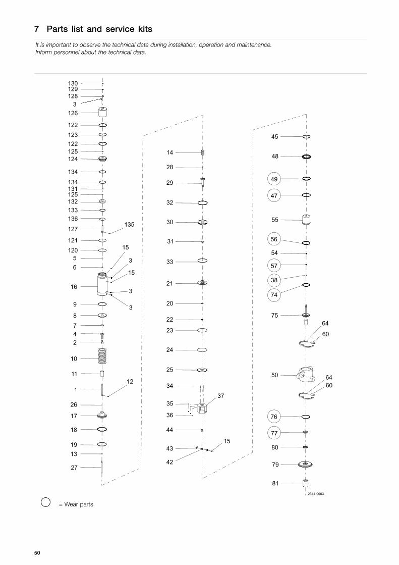
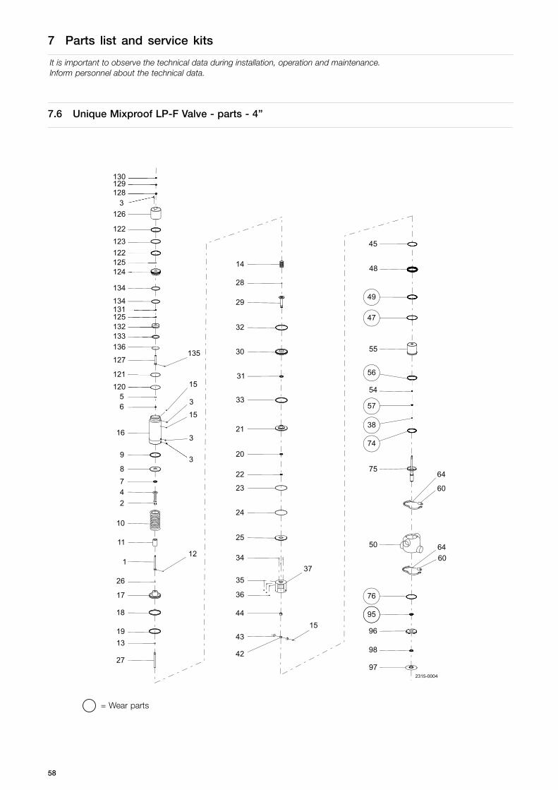
7.6 Unique Mixproof LP-F Valve - parts - 4”
2315-0004
60
3
135
15
136
134
27
1319
18
17
26
112
11
10
24
87
43
9
42
15
16
44
3
15
3
6 35
3734
36
121120
127
25
35
133
24
132125131134
23
97
22
124
98
20
125122
96
123
21
122
95
76
126
6460
128
31
33
129130
50
30
64
32
29
28
75
14
74
38
57
54
56
55
47
49
48
45
= Wear parts
58
7 Parts list and service kits
It is important to observe the technical data during installation, operation and maintenance.Inform personnel about the technical data.
Parts list
Pos. Qty Denomination
Cpl. Actuator1 1 Upper stem2 4 Screw3 4 Air fitting4 1 Stop for upper piston5 1 O-ring, NBR6 1 Guide ring, Turcite7 1 O-ring, NBR8 1 Upper piston9 1 O-ring, NBR10 1 Spring assembly11 1 Distance spacer12 1 Pin13 1 Washer14 1 Spring assembly15 3 Plug16 1 Cylinder17 1 Main piston18 1 Guide ring, Turcite19 1 O-ring, NBR20 1 O-ring, NBR21 1 Bottom22 1 Guide ring, Turcite23 1 O-ring, NBR24 1 Retaining ring25 1 Cover disk26 1 O-ring, NBR27 1 Inner stem28 1 O-ring29 1 Piston rod30 1 Lower piston31 1 O-ring, NBR32 1 Guide ring, Turcite33 1 O-ring, NBR
Parts list
Pos. Qty Denomination
34 3 Bolt35 3 Washer36 3 Nut42 1 Spindle liner43 2 Clamp44 1 Lock45 1 Guide ring, PTFE48 1 Upper sealing element54 1 Guide ring, PTFE55 1 Upper plug60 2 Hexnut64 2 Clamp without nut75 1 Lower plug96 1 Lower sealing element, upper part97 1 Lower sealing element, lower part98 1 Guide ring, Turcite120 1 Lock ring121 1 O-ring, NBR122 2 Guide ring123 1 O-ring, NBR124 1 Piston125 2 O-ring, NBR126 1 Cylinder127 1 Upper stem, cpl.128 1 Bushing129 1 O-ring130 1 O-ring131 1 Guide ring, Turcite132 1 Inner piston133 1 O-ring134 2 O-ring135 1 Screw136 1 Lock ring
59

7 Parts list and service kits
It is important to observe the technical data during installation, operation and maintenance.Inform personnel about the technical data.
7.7 Unique Mixproof LP-F Valve - parts - 6”
27
19
13
18
17
26
1 12
10
11
24
7
22
8
9
43
4215
16
37
65
34
15
3
3
36
35
25
23
64
24
20
3
21
64
60
33
97
31
96
30
98
32
95
76
29
28
14
50
75
74
38
57
54
56
47
55
49
48
45
44
2315-0005
60
= Wear parts
60

7 Parts list and service kits
It is important to observe the technical data during installation, operation and maintenance.Inform personnel about the technical data.
Parts list
Pos. Qty Denomination
Cpl. Actuator1 1 Upper stem2 4 Screw3 3 Air fitting4 1 Stop for upper piston5 1 O-ring, NBR6 1 Guide ring, Turcite7 1 O-ring, NBR8 1 Upper piston9 1 O-ring, NBR10 1 Spring assembly11 1 Distance spacer12 1 Pin13 1 Washer14 1 Spring assembly15 2 Plug16 1 Cylinder17 1 Main piston18 1 Guide ring, Turcite19 1 O-ring, NBR20 1 O-ring, NBR21 1 Bottom22 1 Guide ring, Turcite23 1 O-ring, NBR24 1 Retaining ring25 1 Cover disk26 1 O-ring, NBR27 1 Inner stem28 1 O-ring29 1 Piston rod30 1 Lower piston31 1 O-ring, NBR32 1 Guide ring, Turcite33 1 O-ring, NBR34 3 Bolt35 3 Washer36 3 Nut42 1 Spindle liner43 2 Clamp44 1 Lock45 1 Guide ring, PTFE48 1 Upper sealing element54 1 Guide ring, PTFE55 1 Upper plug60 2 Hexnut64 2 Clamp without nut75 1 Lower plug96 1 Lower sealing element, upper part97 1 Lower sealing element, lower part98 1 Guide ring, Turcite
61

7 Parts list and service kits
It is important to observe the technical data during installation, operation and maintenance.Inform personnel about the technical data.
7.8 Unique Mixproof LP-F Valve - service kits - 4" and 6"
TYPE 22-00 TYPE 22-90
TYPE 12-00 TYPE 12-90 TYPE 21-00 TYPE 21-90
TYPE 11-00 TYPE 11-90 TYPE 11-180 TYPE 11-270
TD 449-014_3
Service Kits
48
75
79
55
TD 481-002
62

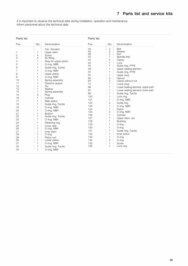
7 Parts list and service kits
It is important to observe the technical data during installation, operation and maintenance.Inform personnel about the technical data.
Parts list
Pos. Qty Denomination
37 1 Intermediate piece50 1 Valve body
Service kits
Denomination
4”a Service kit, NBR . . . . . . . . . . . . . . . . . . . . . . . . . . . . . . . . . . . . . . . . . . . . . . . 9611-92-6865a Service kit, EPDM . . . . . . . . . . . . . . . . . . . . . . . . . . . . . . . . . . . . . . . . . . . . . . 9611-92-6866a Service kit, HNBR . . . . . . . . . . . . . . . . . . . . . . . . . . . . . . . . . . . . . . . . . . . . . . 9611-92-6867a Service kit, FPM . . . . . . . . . . . . . . . . . . . . . . . . . . . . . . . . . . . . . . . . . . . . . . . . 9611-92-6868
6”
a Service kit, NBR . . . . . . . . . . . . . . . . . . . . . . . . . . . . . . . . . . . . . . . . . . . . . . . 9611-92-6857a Service kit, EPDM . . . . . . . . . . . . . . . . . . . . . . . . . . . . . . . . . . . . . . . . . . . . . . 9611-92-6858a Service kit, HNBR . . . . . . . . . . . . . . . . . . . . . . . . . . . . . . . . . . . . . . . . . . . . . . 9611-92-6859a Service kit, FPM . . . . . . . . . . . . . . . . . . . . . . . . . . . . . . . . . . . . . . . . . . . . . . . . 9611-92-6860
63

How to contact Alfa LavalContact details for all countries arecontinually updated on our website.Please visit www.alfalaval.com to access the information directly.
© Alfa Laval Corporate ABThis document and its contents is owned by Alfa Laval Corporate AB and protected by laws governing intellectual property and thereto related rights. It is the responsibility of the user of thisdocument to comply with all applicable intellectual property laws. Without limiting any rights related to this document, no part of this document may be copied, reproduced or transmitted in anyform or by any means (electronic, mechanical, photocopying, recording, or otherwise), or for any purpose, without the expressed permission of Alfa Laval Corporate AB. Alfa Laval Corporate ABwill enforce its rights related to this document to the fullest extent of the law, including the seeking of criminal prosecution.