instruction manual - ares rc
TRANSCRIPT
1
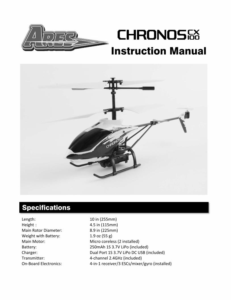
Length: 10 in (255mm) Height : 4.5 in (115mm) Main Rotor Diameter: 8.9 in (225mm) Weight with Battery: 1.9 oz (55 g) Main Motor: Micro coreless (2 installed) Battery: 250mAh 1S 3.7V LiPo (included) Charger: Dual Port 1S 3.7V LiPo DC USB (included) Transmitter: 4‐channel 2.4GHz (included) On‐Board Electronics: 4‐in‐1 receiver/3 ESCs/mixer/gyro (installed)
Specifications
Instruction Manual
2
Specifications ............................................................................................................................................ 1
Introduction .............................................................................................................................................. 3
Safety Precautions and Warnings ............................................................................................................. 4
FCC Information ........................................................................................................................................ 4
Chronos CX 100 RTF Contents .................................................................................................................. 5
Required to Complete............................................................................................................................... 5
Before the First Flight Checklist ................................................................................................................ 6
Flight Checklist .......................................................................................................................................... 6
LiPo Battery Warnings and Usage Guidelines .......................................................................................... 7
Charging the LiPo Flight Battery ............................................................................................................... 9
Installing the Transmitter Batteries ........................................................................................................ 12
Transmitter Details ................................................................................................................................. 12
Transmitter Dual Rates ........................................................................................................................... 15
Transmitter Control Mode Selection (Mode 2/Mode 4) ........................................................................ 16
Flight Controls and Trimming ................................................................................................................. 17
Removing and Installing the LiPo Flight Battery ..................................................................................... 21
Control Unit Initialization and Arming .................................................................................................... 23
Selecting a Flying Area ............................................................................................................................ 25
Flying ....................................................................................................................................................... 26
Digital Video/Still Camera ....................................................................................................................... 28
Transmitter and Receiver Binding/Linking ............................................................................................. 30
Warranty, Support and Service .............................................................................................................. 30
Replacement Parts List ........................................................................................................................... 31
Exploded View Parts Listing .................................................................................................................... 32
Exploded View ........................................................................................................................................ 33
Notes ....................................................................................................................................................... 34
Notes ....................................................................................................................................................... 35
Table of Contents
3
The Ares™ [air‐eez] Chronos CX 100 is the easiest way for anyone to shoot video or take photos while
flying an RC heli! The CX 100’s factory‐installed digital camera is easily operated while flying by just
pressing a button on the transmitter. The camera also includes a 2GB memory card with enough storage for you to keep up to 90 minutes of video or hundreds of photos!
Flying the CX 100 is easy too because it features a coaxial, counter‐rotating blade design, fully‐
proportional controls and a computerized gyro that work together to provide maximum stability and
maneuverability that will have even first‐time pilots hovering like a pro in no time. Plus, the Chronos
CX 100’s ultra‐micro size allows you to fly indoors in nearly any space.
The Chronos CX 100 is an RTF (Ready‐To‐Fly) aircraft, so the lightweight and durable airframe arrives
100% factory‐assembled and everything needed to fly is in the box, including AA batteries for the
4‐channel transmitter equipped with 2.4GHz technology, a backlit LCD screen, dual rates and
selectable control modes. Also included is a 250mAh 1S 3.7V LiPo battery that’s easy to “swap”
between flights and a convenient dual‐port USB charger that allows you to charge two batteries at
once. With nothing extra to buy or assemble, you can be flying and taking videos and photos within
minutes of opening the box.
And although the Chronos CX 100 is ready to fly right out the box, please take the time to read through this manual for information on battery safety and charging, flight controls and more before making your first flight. Please also visit our web site at www.Ares‐RC.com for additional information including product updates, bulletins, videos and more.
Introduction

4
Failure to use this product in the intended manner as described in the following instructions can result in damage and/or personal injury. A Radio Controlled (RC) airplane/helicopter/quadcopter is not a toy! If misused it can cause serious bodily harm and damage to property.
Keep items that could become entangled away from the propeller/rotor blades, including loose clothing, tools, etc. Be especially sure to keep your hands, face and other parts of your body away from the propeller/rotor blades.
As the user of this product you are solely and wholly responsible for operating it in a manner that does not endanger yourself and others or result in damage to the product or the property of others.
This model is controlled by a radio signal that is subject to possible interference from a variety of sources outside your control. This interference can cause momentary loss of control so it is advisable to always keep a safe distance from objects and people in all directions around your model as this will help to avoid collisions and/or injury.
• Never operate your model if the voltage of the batteries in the transmitter is too low.• Always operate your model in an open area away from obstacles, people, vehicles, buildings,
etc.• Carefully follow the directions and warnings for this and any optional support equipment
(chargers, rechargeable batteries, etc.).• Keep all chemicals, small parts and all electronic components out of the reach of children.• Moisture causes damage to electronic components. Avoid water exposure to all electronic
components, parts, etc. not specifically designed and protected for use in water.• Never lick or place any portion of the model in your mouth as it could cause serious injury or
even death.
This device complies with part 15 of the FCC rules. Operation is subject to the following two conditions: (1) This device may not cause harmful interference, and (2) this device must accept any interference received, including interference that may cause undesired operation.
Caution: Changes or modifications not expressly approved by the party responsible for compliance could void the user’s authority to operate the equipment.
This product contains a radio transmitter with wireless technology which has been tested and found to be compliant with the applicable regulations governing a radio transmitter in the 2.400GHz to 2.4835GHz frequency range.
The associated regulatory agencies of the following countries recognize the noted certifications for this product as authorized for sale and use: USA
Safety Precautions and Warnings
FCC Information
5
Item Description
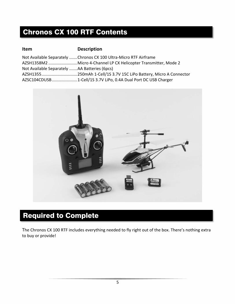
Not Available Separately ....... Chronos CX 100 Ultra‐Micro RTF Airframe AZSH1358M2 ......................... Micro 4‐Channel LP CX Helicopter Transmitter, Mode 2 Not Available Separately ....... AA Batteries (6pcs) AZSH1355 ............................... 250mAh 1‐Cell/1S 3.7V 15C LiPo Battery, Micro A Connector AZSC104CDUSB ...................... 1‐Cell/1S 3.7V LiPo, 0.4A Dual Port DC USB Charger
The Chronos CX 100 RTF includes everything needed to fly right out of the box. There’s nothing extra to buy or provide!
Chronos CX 100 RTF Contents
Required to Complete

6
PLEASE NOTE: This checklist is NOT intended to replace the content included in this instruction manual. Although it can be used as a quick start guide, we strongly suggest reading through this manual completely before proceeding.
Remove and inspect all contents
Plug the dual port DC USB charger into a suitable USB power source
Begin charging the LiPo flight battery (connect the helicopter to the charger directly orconnect the battery to the charger using the included adapter leads)
Install the six (6) AA batteries in the transmitter
Familiarize yourself with the controls
Turn the transmitter on first then turn the helicopter on
Test the controls to confirm proper operation
Find a suitable area for flying
PLEASE NOTE: This checklist is NOT intended to replace the content included in this instruction manual. Although it can be used as a quick start guide, we strongly suggest reading through this manual completely before proceeding.
Always turn the transmitter on first
Turn the helicopter on (after the transmitter is turned on)
Allow the control unit to initialize and arm properly (on a flat/level surface)
Fly the model (take‐off from a flat/level surface)
Land the model (land on a flat/level surface)
Turn the helicopter off (before the transmitter is turned off)
Always turn the transmitter off last
Before the First Flight Checklist
Flight Checklist

7
IMPORTANT NOTE: Lithium Polymer batteries are significantly more volatile than the alkaline, NiCd or NiMH batteries also used in RC applications. All instructions and warnings must be followed exactly to prevent property damage and/or personal injury as mishandling of LiPo batteries can result in fire.
By handling, charging or using the included LiPo battery you assume all risks associated with LiPo batteries. If you do not agree with these conditions please return the complete product in new, unused condition to the place of purchase immediately.
And although the 250mAh 1‐Cell/1S 3.7V 15C LiPo Battery (AZSH1355) included with your Ares™ Chronos CX 100 is intended to be charged safely using the included 104CD 1‐Cell/1S 3.7V LiPo, 0.4A Dual Port DC USB Charger (AZSC104CDUSB) you must read the following safety instructions and warnings before handling, charging or using the LiPo battery.
• You must charge the LiPo battery in a safe area away from flammable materials.
• Never charge the LiPo battery unattended at any time. When charging the battery youshould always remain in constant observation to monitor the charging process and reactimmediately to any potential problems that may occur.
• After flying/discharging the battery you must allow it to cool to ambient/room temperaturebefore recharging.
• To charge the battery you must use only the included 104CD 1‐Cell/1S 3.7V LiPo, 0.4A DualPort DC USB Charger (AZSC104CDUSB) or a suitably compatible LiPo battery charger. Failureto do so may result in a fire causing property damage and/or personal injury. DO NOT use aNiCd or NiMH charger.
• If at any time during the charge or discharge process the battery begins to balloon or swell,discontinue charging or discharging immediately. Quickly and safely disconnect the battery,then place it in a safe, open area away from flammable materials to observe it for at least15 minutes. Continuing to charge or discharge a battery that has begun to balloon or swellcan result in a fire. A battery that has ballooned or swollen even a small amount must beremoved from service completely.
• Store the battery at room temperature, approximately 68–77° Fahrenheit (F), and in a dryarea for best results.
LiPo Battery Warnings and Usage Guidelines

8
When transporting or temporarily storing the battery, the temperature range should befrom approximately 40–100°F. Do not store the battery or model in a hot garage, car ordirect sunlight whenever possible. If stored in a hot garage or car the battery can bedamaged or even catch fire.
Do not over‐discharge the LiPo flight battery. Discharging the LiPo flight battery too lowcan cause damage to the battery resulting in reduced power, flight duration or failure ofthe battery entirely.
LiPo cells should not be discharged to below 3.0V each under load. In the case of the 1‐cell/1S 3.7V LiPo battery used to power the Chronos CX 100 you will not want to allow the battery to fall below 3.0V during flight.
The 4‐in‐1 control unit features a low voltage cutoff (LVC) that cuts power to the motors completely (regardless of the power level you have set with the left‐hand/throttle stick) if the voltage of the battery falls below the 3.0V minimum. If the LVC ever occurs it will be indicated by a blinking red LED on the control unit (the LED mounted in the canopy will also blink). However, to prevent an unexpected loss of power due to triggering the LVC, if you ever find that more than the typical amount of throttle/power is required to hover and/or the helicopter will not ascend/climb even at full power you should land the model and turn it off immediately to prevent over‐discharge.
And while it is possible to power the model up and fly again after the LVC occurs this is NOT recommended. Continued discharging can cause permanent damage to the LiPo battery resulting in reduced power output and/or shortened flight durations during subsequent flights (or failure of the battery entirely).
Also, it is not recommended that you fly to the LVC every time you fly. Instead you should be aware of the power level of the battery/helicopter throughout the flight, and if at any time the helicopter begins to require more throttle/power than typical to maintain hover, and/or will not ascend/climb even at full power, you should land the helicopter and turn it off immediately. Repeatedly discharging the battery to the LVC can still cause permanent damage to the battery so it’s best to use a timer or stop‐watch to time the duration of your flights and to stop flying at a reasonable time before the LVC is reached.
IMPORTANT NOTE: DO NOT LEAVE THE HELICOPTER TURNED ON UNLESS IT IS READY TO BE FLOWN. IF THE HELICOPTER IS LEFT TURNED ON WHEN IT IS NOT IN USE THE LIPO BATTERY WILL BE OVER‐DISCHARGED BY THE SMALL AMOUNT OF CURRENT THE ON‐BOARD ELECTRONICS AND LEDs CONSUME. It can sometimes take a few hours or even up to a few days to over‐discharge the battery this way but doing so will likely cause permanent damage to or failure of the battery entirely (which is not covered under warranty).
9
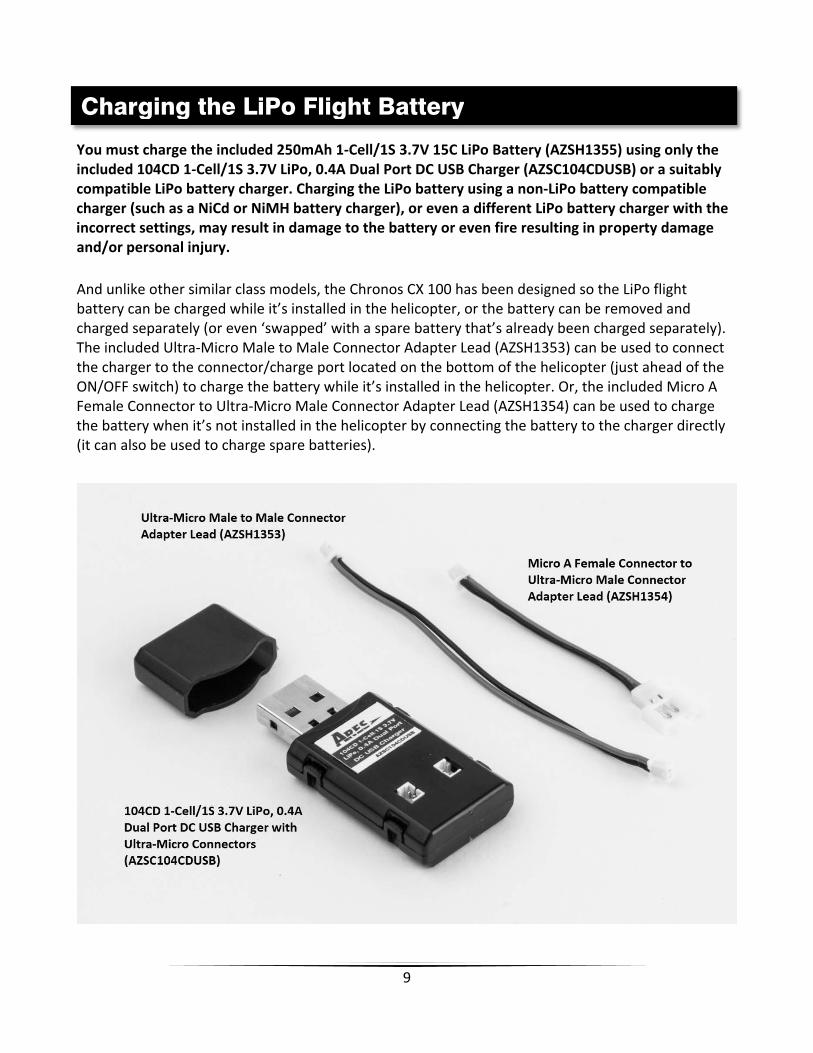
You must charge the included 250mAh 1‐Cell/1S 3.7V 15C LiPo Battery (AZSH1355) using only the included 104CD 1‐Cell/1S 3.7V LiPo, 0.4A Dual Port DC USB Charger (AZSC104CDUSB) or a suitably compatible LiPo battery charger. Charging the LiPo battery using a non‐LiPo battery compatible charger (such as a NiCd or NiMH battery charger), or even a different LiPo battery charger with the incorrect settings, may result in damage to the battery or even fire resulting in property damage and/or personal injury.
And unlike other similar class models, the Chronos CX 100 has been designed so the LiPo flight battery can be charged while it’s installed in the helicopter, or the battery can be removed and charged separately (or even ‘swapped’ with a spare battery that’s already been charged separately). The included Ultra‐Micro Male to Male Connector Adapter Lead (AZSH1353) can be used to connect the charger to the connector/charge port located on the bottom of the helicopter (just ahead of the ON/OFF switch) to charge the battery while it’s installed in the helicopter. Or, the included Micro A Female Connector to Ultra‐Micro Male Connector Adapter Lead (AZSH1354) can be used to charge the battery when it’s not installed in the helicopter by connecting the battery to the charger directly (it can also be used to charge spare batteries).
Charging the LiPo Flight Battery

10
Please follow these steps to charge the LiPo flight battery with the included charger:
Connect the dual port DC USB charger to a suitable 5V USB port on a computer or otherdevice. Another option is to plug the optional 5005PS 100‐240V AC to 5V DC USB, 0.5‐AmpPower Supply (AZSC5005PS) into a compatible 100‐240V AC outlet then to connect thecharger to the power supply/AC adapter accordingly. The power supply/AC adapter ispowered on when the LED indicator glows solid green.
To charge the LiPo flight battery while it’s installed in the helicopter use the included Ultra‐Micro Male to Male Connector Adapter Lead to connect the charger to the connector/chargeport located on the bottom of the helicopter. YOU MUST BE CAREFUL TO ENSURE PROPERPOLARITY BEFORE MAKING THE CONNECTIONS by aligning the red color positive (+) wirelead with the ‘ON’ marking on the bottom of the canopy and by orienting it toward the endof the charger without the USB connector. And although the ultra‐micro connectors are‘keyed’ to minimize the risk of a reverse polarity connection, if you force them it is possible tomake connection with the incorrect polarity potentially causing damage to thehelicopter/control unit, the battery and/or the charger. When the connectors are properlyaligned for correct polarity only a minimal amount of pressure should be required to achievethe light ‘click’ that indicates secure connection.
NOTE: The reference photos show the dual port DC USB charger charging a spare LiPo battery (AZSH1355; sold separately) while charging the battery installed in the helicopter at the same time. You can also purchase an additional Micro A Female Connector to Ultra‐Micro Male Connector Adapter Lead (AZSH1354) to charge two batteries that are not installed in the helicopter at the same time.

11
To charge the LiPo flight battery when it’s not installed in the helicopter use the included Micro A Female Connector to Ultra‐Micro Male Connector Adapter Lead (AZSH1354) to connect the battery to the charger directly. YOU MUST BE CAREFUL TO ENSURE PROPER POLARITY BEFORE MAKING THE CONNECTIONS by orienting/aligning the wire leads of the battery and adapter lead so they’re ‘red to red’ and ‘black to black’. You’ll also need to orient the red color positive (+) wire lead toward the end of the charger without the USB connector. And although the connectors are ‘keyed’ to minimize the risk of a reverse polarity connection, if you force them it is possible to make connection with the incorrect polarity potentially causing damage to the battery and/or charger. When the connectors are properly aligned for correct polarity only a minimal amount of pressure should be required to achieve the light ‘click’ that indicates secure connection.
When the helicopter and/or battery are connected to the charger securely and with theproper polarity the LED indicator will glow solid red (there is an LED indicator for each chargeport). The battery will be charging any time the LED indicator is glowing solid red.
It will take approximately 1.0–1.5 hours to fully charge a mostly or fully discharged (not over‐discharged) battery from a suitable power source. And when the battery is fully charged theLED indicator will stop glowing entirely. When the LED indicator is no longer glowing you candisconnect the helicopter and/or battery from the charger/adapted lead as it is now fullycharged and ready for use.
NOTE: When using both charge ports at the same time to charge two (2) fully discharged (not over‐discharged) batteries, the charge time may increase by approximately 30 minutes per battery (or more) depending on the amount of power available from your source.
NOTE: The LiPo flight battery included with your model will arrive partially charged. For this reason the initial charge may only take approximately 30–45 minutes.
NOTE: It’s safer and better for the longevity of the battery to store it only partially charged for any length of time. Storing the battery at approximately 50% charge (which is approximately 3.85V per cell) is typically best, however, it will take some careful management of the charge time and the use of a volt meter to achieve this voltage. If you have the equipment and skills to achieve the 50% charge level for storage it is recommended. If not, simply be sure to not store the battery fully charged whenever possible. In fact, as long as the battery will be stored at approximately room temperature and for no more than a few weeks before the next use, it may be best to store the battery in the discharged state after the last flight (as long as the battery was not over‐discharged on the last flight).

12
Install the six (6) included AA batteries in the back of the transmitter by first removing the battery compartment cover/door. Ensure proper polarity of the batteries before installing them as noted by the markings molded into the battery compartment, then re‐install the compartment cover/door.
Check for proper operation of the transmitter by sliding the power switch to the ON position (slide it upward). The red LED indicator (above the switch) will begin to blink slowly and the LCD screen will power on. This indicates the transmitter is powered on and the AA batteries are installed correctly.
NOTE: The transmitter is equipped with a low voltage battery alarm. If at any time the audible alarm is on it will be necessary to replace the AA batteries with new ones.
The Chronos CX 100 includes a Micro 4‐Channel LP CX Helicopter Transmitter equipped with 2.4GHz technology, dual rates, digital trims and a backlit LCD screen.
Installing the Transmitter Batteries
Transmitter Details

13
Control Mode Selection and Camera Function Button The button located near the top left‐hand corner of the transmitter has two functions. By pressing the button and holding it down while turning the transmitter on the first function is to select and set the control mode. You can select either Mode 2 or Mode 4 which will determine if the left‐hand (Mode 2) or right‐hand (Mode 4) stick controls the rudder channel. Please see the ‘Transmitter Control Mode Selection’ section of this manual for more information.
After the transmitter is powered on the second function of the button is to control the functions of the digital camera. Please see the ‘Digital Video/Still Camera’ section of this manual for more information.
Dual Rate Button The button located near the top right‐hand corner of the transmitter is used to toggle between the ‘Dual Rates’ available for the elevator control/channel. Please see the ‘Transmitter Dual Rates’ section of this manual for more information.
LCD Screen The unique backlit LCD screen displays a variety of data when the transmitter is powered on:
Battery Power Indicator This indicator shows the approximate amount of AA battery power remaining for the transmitter. NOTE: The transmitter is also equipped with a low voltage battery alarm. If at any time the audible alarm is on it will be necessary to replace the AA batteries with new ones.
14
Control Mode Indicator
This indicator shows which control mode is currently selected (please see the ‘Transmitter Control Mode Selection’ section of this manual for more information). The ‘2’ indicator for Mode 2 is located on the left side of the helicopter illustration and the ‘4’ indicator for Mode 4 is located on the right side.
Throttle Channel Output/Stick Position Indicator
This indicator shows the approximate throttle channel output/stick position.
Throttle Channel Trim Position Indicator
This indicator shows the approximate throttle channel trim position. Also, you should always have this set to the middle or lower than the middle position (using the throttle trim lever) to properly arm the 4‐in‐1 control unit ESCs and to ensure it’s possible to stop the motors/rotor blades from spinning completely when the left‐hand/throttle stick is in the lowest possible position.
Elevator Channel Output/Stick Position Indicator
This indicator shows the approximate elevator channel output/stick position.
Elevator Channel Trim Position Indicator
This indicator shows the approximate elevator channel trim position.
IMPORTANT NOTE: Although the position of the elevator trim can be changed, because the Chronos CX 100 is equipped with a motor for elevator control the trim has no actual effect on the helicopter.
Rudder Channel Output/Stick Position Indicator (for Mode 2 and Mode 4)
This indicator shows the approximate rudder channel output/stick position.
IMPORTANT NOTE: Although rudder channel control can be set on the left‐hand (for Mode 2) or right‐hand (for Mode 4) stick, the rudder channel output/stick position is always shown by the same indicator (please see the ‘Transmitter Control Mode Selection’ section of this manual for more information).
Rudder Channel Trim Position Indicator (for Mode 2 and Mode 4)
This indicator shows the approximate rudder channel trim position. The trim position should be adjusted as needed during flight (using the rudder trim lever located below the left‐hand stick for Mode 2 or below the right‐hand stick for Mode 4) to ensure the nose of the helicopter does not constantly turn (yaw) left or right when ‘hovering’ and without any rudder channel/control input.
IMPORTANT NOTE: Although rudder channel control and trim can be set on the left‐hand (for Mode 2) or right‐hand (for Mode 4) stick, the rudder channel trim position is always shown by the same indicator (please see the ‘Transmitter Control Mode Selection’ section of this manual for more information).

15
Dual Rate Status Indicator
This indicator is shows the control rate currently selected; ‘L’ for low rate and ‘H’ for high rate (please see the ‘Transmitter Dual Rates’ selection of this manual for more information).
Recording Video Indicator
This indicator shows when the digital camera is recording video.
Still Photo Indicator
This indicator shows when the digital camera is taking a still photo.
The button located near the top right‐hand corner of the transmitter is used to toggle between the ‘High’ (H) and ‘Low’ (L) control rates, also known as ‘Dual Rates’, available for the rudder and elevator controls/channels. You can toggle between the high and low rates by pressing the button, after which you’ll feel a ‘click’ and also hear an audible beep/tone. The selected control rate will be displayed as ‘H’ for high rate and ‘L’ for low rate near the bottom left‐hand corner of the LCD screen.
IMPORTANT NOTE: The transmitter will automatically default to the ‘Low’ (L) rate mode each time it’s powered on.
The L/low rate mode is typically preferred by (and recommended best for) first‐time, low‐time and other pilots interested most in a reduced amount of control authority that allows for smoother and more easily controlled hovering and flying.
By pressing the dual rate button while in the L/low rate mode you’ll switch to the H/high rate mode. You’ll know you’ve switched to the H/high rate mode after feeling a ‘click’ and hearing a single beep/tone.
In the H/high rate mode the controls are allowed to reach their maximum values. This mode is typically preferred by experienced pilots interested most in maximum control authority.
If you ever switch to the H/high rate mode you’ll know you’ve switched back to the L/low rate mode by pressing the dual rate button, feeling the click and also hearing a single beep/tone.
Transmitter Dual Rates
16
The Micro 4‐Channel LP CX Helicopter Transmitter included with the Chronos CX 100 features unique and exclusive software that makes it possible to select and set the ‘control mode’. Typically 3‐channel RC helicopters include transmitters that are set to ‘Mode 4’ which places throttle channel control only on the left‐hand stick and rudder and elevator channel control on the right‐hand stick. However, 4+ channel RC helicopters typically include transmitters that are set to ‘Mode 2’ which places throttle and rudder channel control on the left‐hand stick and elevator channel control (plus the added control/channel of aileron) on the right‐hand stick.
IMPORTANT NOTE: If you plan to fly 4+ channel RC helicopters (or even quadcopters and airplanes) in the future we strongly recommend setting the transmitter to Mode 2.
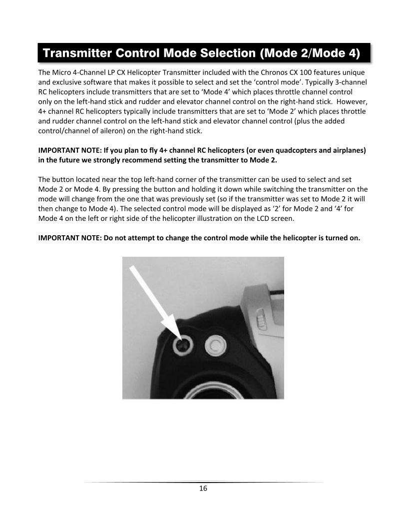
The button located near the top left‐hand corner of the transmitter can be used to select and set Mode 2 or Mode 4. By pressing the button and holding it down while switching the transmitter on the mode will change from the one that was previously set (so if the transmitter was set to Mode 2 it will then change to Mode 4). The selected control mode will be displayed as ‘2’ for Mode 2 and ‘4’ for Mode 4 on the left or right side of the helicopter illustration on the LCD screen.
IMPORTANT NOTE: Do not attempt to change the control mode while the helicopter is turned on.
Transmitter Control Mode Selection (Mode 2/Mode 4)

17
In the event you are not familiar with the controls of the Chronos CX 100 please take the time to familiarize yourself with them as follows and before attempting your first flight:
Mode 2 and Mode 4 Throttle and Elevator Channel Flight Controls
The left‐hand stick on the transmitter controls the throttle (climb/descend) channel. When the left‐hand stick (also known as the ‘throttle’ stick) is in the lowest possible position the rotor blades will not spin. Moving the stick upward will increase the RPMs/speed of the rotor blades. Increasing the RPMs/speed of the rotor blades will cause the model to climb.
Decreasing the RPMs/speed of the rotor blades by lowering the left‐hand stick will cause the model to descend.
After lifting the model off the ground you can ‘hover’ by carefully moving the left‐hand stick up and down slightly as needed so the model will maintain altitude without climbing or descending.
Flight Controls and Trimming

18
The right‐hand stick controls the elevator (pitch fore/aft) channel. Pushing the stick forward will cause the ‘tail’ motor and rotor blade/propeller to spin in order to pitch the nose of the helicopter downward so it can be flown forward.
Pulling the stick backward will cause the tail motor and rotor blade/propeller to spin in the opposite direction in order to pitch the tail of the helicopter downward so it can be flown backward.
The elevator trim lever is located immediately to the left of the right‐hand stick. And although the position of the elevator trim can be changed, because the Chronos CX 100 is equipped with a motor for elevator control the trim has no actual effect on the helicopter.
19
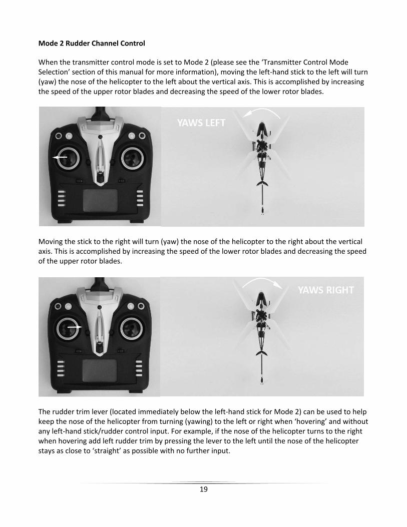
Mode 2 Rudder Channel Control
When the transmitter control mode is set to Mode 2 (please see the ‘Transmitter Control Mode Selection’ section of this manual for more information), moving the left‐hand stick to the left will turn (yaw) the nose of the helicopter to the left about the vertical axis. This is accomplished by increasing the speed of the upper rotor blades and decreasing the speed of the lower rotor blades.
Moving the stick to the right will turn (yaw) the nose of the helicopter to the right about the vertical axis. This is accomplished by increasing the speed of the lower rotor blades and decreasing the speed of the upper rotor blades.
The rudder trim lever (located immediately below the left‐hand stick for Mode 2) can be used to help keep the nose of the helicopter from turning (yawing) to the left or right when ‘hovering’ and without any left‐hand stick/rudder control input. For example, if the nose of the helicopter turns to the right when hovering add left rudder trim by pressing the lever to the left until the nose of the helicopter stays as close to ‘straight’ as possible with no further input.

20
Mode 4 Rudder Channel Control
When the transmitter control mode is set to Mode 4 (please see the ‘Transmitter Control Mode Selection’ section of this manual for more information), moving the right‐hand stick to the left will turn (yaw) the nose of the helicopter to the left about the vertical axis. This is accomplished by increasing the speed of the upper rotor blades and decreasing the speed of the lower rotor blades.
Moving the stick to the right will turn (yaw) the nose of the helicopter to the right about the vertical axis. This is accomplished by increasing the speed of the lower rotor blades and decreasing the speed of the upper rotor blades.
The rudder trim lever (located immediately below the right‐hand stick for Mode 4) can be used to help keep the nose of the helicopter from turning (yawing) to the left or right when ‘hovering’ and without any right‐hand stick/rudder control input. For example, if the nose of the helicopter turns to the right when hovering add left rudder trim by pressing the lever to the left until the nose of the helicopter stays as close to ‘straight’ as possible with no further input.
And once you’re familiar with the primary controls of the helicopter you’re almost ready to fly!

21
As noted in the ‘Charging the LiPo Flight Battery’ section of this manual, you can charge the battery while it’s installed in the helicopter or you can remove and charge it separately (or ‘swap’ it with a spare battery that’s already been charged separately). To remove the LiPo flight battery you’ll first need to remove the canopy. Carefully pull the left and right ends of the canopy off of the mounts then slowly slide it forward to expose the battery, control unit and wire leads.
IMPORTANT NOTE: The LED mounted in the canopy is not intended to be removed. Be careful to not damage the wire leads that connect to the LED when removing (and installing) the canopy. Also, you can disconnect the wire leads and connector from the control unit entirely if preferred (though we DO NOT recommend disconnecting and reconnecting often as it can damage the connectors and/or control unit over time).
Disconnect the LiPo flight battery from the wire leads and connector attached to the control unit, then carefully remove it from the mount (slide it upwards while gripping the sides of the battery, DO NOT pull on the wire leads!). The battery can now be charged separate from the helicopter.
After the LiPo battery has been fully charged it’s ready to be installed in the helicopter. Install the battery by sliding it back into the mount with the wire leads oriented upward.
AND AFTER INSTALLING THE BATTERY IN THE MOUNT/HELICOPTER YOU MUST BE CAREFUL TO ENSURE PROPER POLARITY BEFORE CONNECTING IT TO THE 4‐IN‐1 CONTROL UNIT. By orienting/aligning the wire leads of the battery and control unit so they’re ‘red to red’ and ‘black to black’ you’ll be able to make the connection with correct polarity. Also, before making the connection check to be sure the ON/OFF switch located on the bottom of the helicopter is set to the OFF position.
Also, although the ‘Micro A’ connectors are ‘keyed’ to minimize the risk of a reverse polarity connection, if you force them it is possible to make connection with incorrect/reversed polarity potentially causing damage to the control unit and/or battery. When the connectors are properly aligned for correct polarity, connecting them should require only a minimal amount of pressure to achieve the light ‘click’ that indicates secure connection.
Removing and Installing the LiPo Flight Battery

22
After making a secure connection carefully ‘tuck’ the wire leads and connectors between the control unit and battery.
Re‐install the canopy by carefully sliding it over the control unit and battery while also aligning the mounting ‘slots’ inside the canopy with the mounting ‘tabs’ located on the left and right sides of the frame. Then carefully slip the left and right ends of the canopy over the mounts by aligning them with the mounting holes.

23
The Chronos CX 100 is equipped with a compact and advanced 4‐in‐1 control unit. The control unit is a lightweight combination of a 2.4GHz receiver, three electronic speed controls (ESCs), a mixer and gyro. The control unit is also equipped with an LED that provides various indications.
This checklist includes the steps you must follow to ensure proper initialization, arming and operation of the control unit:
Before each flight you must ALWAYS turn the transmitter on BEFORE turning thehelicopter on. Never turn the helicopter on before powering the transmitter on first.After each flight you should always turn the helicopter off before turning thetransmitter off.
IMPORTANT NOTE: It’s important that you turn the helicopter on within 20 seconds of turning on the transmitter. Failure to turn the helicopter on within 20 seconds of turning on the transmitter will prevent the transmitter from binding/linking to the receiver/control unit.
The left‐hand/throttle stick must be set in the lowest possible position in order for thecontrol unit to initialize and arm properly. Failure to lower the stick to the lowestpossible position can prevent the ESCs from arming and/or the gyro from initializingproperly.
Control Unit Initialization and Arming
24
With the throttle stick in the lowest possible position ensure that the stick is‘centered’ left to right and that the right‐hand stick is ‘centered’ left to right as well asup and down. DO NOT move the sticks as you turn the transmitter on to avoidchanging the proper center/neutral positions of the controls.
IMPORTANT NOTE: Moving the control sticks while turning the transmitter on can changethe proper center/neutral positions of the controls making it difficult to control the modeland impossible to ‘trim it out’ correctly. And if you ever find this to be the case then simplyturn the helicopter off, turn the transmitter off then follow the steps to properly turn onand initialize the transmitter and control unit.
Turn the transmitter on and confirm that the LED indicator (above the power switch)begins to blink slowly while the LCD screen powers on.
NOTE: If this will be the first flight, or the first flight following repairs, you should ‘center’the rudder channel trim. Use the digital trim lever to determine the center trim position byreferencing the LCD screen (please see the ‘Transmitter Details’ section of this manual formore information).
After the transmitter is turned on locate the power switch on the bottom of thehelicopter then slide it to the ‘ON’ position. The LED indicator on the control unit (andthe LED mounted in the canopy) will begin to blink/flash rapidly then will blink/flashslowly before changing to glow solid red.
IMPORTANT NOTE: AFTER TURNING THE HELICOPTER ON IT’S IMPORTANT TO NOT MOVE OR ROTATE IT ONCE THE RED LED ON THE CONTROL UNIT BEGINS TO BLINK/FLASH CONFIRMING THAT THE INITIALIZATION PROCESS AND CALIBRATION OF THE GYRO HAS BEGUN. IF YOU DO MOVE/ROTATE THE HELICOPTER TOO MUCH WHILE THE LED IS BLINKING/FLASHING IT MAY AFFECT INITIALIZATION/CALIBRATION OF THE GYRO WHICH COULD REQUIRE SIGNIFICANT RUDDER CHANNEL TRIM ADJUSTMENTS AND/OR PREVENT THE GYRO FROM WORKING DURING THE PENDING FLIGHT. IF THIS HAPPENS YOU MUST TURN THE HELICOPTER OFF AND REPEAT THE INITIALIZATION/CALIBRATION PROCESS.
When the LED indicator glows solid red the control unit is initialized and ready forflight. Use caution as the upper and lower rotor blades will now spin when you raisethe left‐hand/throttle stick!
25
In case the LED indicator does not change to glow solid red:
If the LED indicator on the control unit continues to blink/flash slowly you do not have apositive radio frequency (RF) link between the transmitter and the receiver in the controlunit. First, check to be sure the transmitter is powered on and that the LED indicator onthe transmitter is glowing solid red. If the transmitter is powered on and functioningproperly, turn the helicopter off then turn the transmitter off. Turn the transmitter backon then turn the helicopter on (within 20 second of turning the transmitter on) and nowthe control unit should initialize and arm properly.
In case the LED indicator does change to glow solid red but you have no control of the main motors/rotor blades:
If the LED indicator on the control unit changes to glow solid red, but the LED indicator onthe transmitter is blinking/flashing and you do not have control of the main motors/rotorblades, you have a positive RF link between the transmitter and the receiver in the controlunit but the ESCs/motors did not arm because the left‐hand/throttle stick and/or thethrottle trim may not be set to the correct position. Check to be sure the left‐hand/throttle stick is in the lowest possible position, and that the throttle trim is set to themiddle or lower than the middle position, and once in the correct position theESCs/motors will arm accordingly.
After confirming the control unit is initialized and the ESCs/motors have armed properly your Chronos CX 100 is ready to fly. However, please review the following sections of the manual BEFORE proceeding with the first flight.
When you’re ready to make your first flight you’ll want to select an open indoor area free of people and obstructions. We suggest an area with approximately 10‐feet by 10‐feet of floor space and 8‐foot ceilings when making your first few flights.
After you’ve properly trimmed the helicopter and become familiar with its handling and capabilities you’ll be able to fly in other smaller and less open areas due to its ultra‐micro size and excellent controllability.
PLEASE NOTE: The Chronos CX 100 is designed to ONLY be flown indoors.
Selecting a Flying Area

26
Now that you’ve selected a suitable flying area you’re ready to fly! And when making your first flights we suggest following these steps:
Increase the speed of the rotor blades until the model begins to lift off by raising the left‐hand/throttle stick SLOWLY. DO NOT raise the stick too quickly as the model could climb toofast causing you to lose control and/or make contact with the ceiling or other objects above(this is one of the most common ways most first‐time pilots crash).
Lift the model off the ground approximately 18‐24 inches and concentrate on balancing theleft‐hand/throttle stick position so the helicopter holds a steady hover altitude. It may also behelpful to make a few short ‘hops’ to an altitude of just a few inches until you’re familiar andmore comfortable with the control inputs and trim settings required to maintain a steadyhover and altitude. However, keep in mind that when only a few inches off the ground you’llbe in ‘ground effect’ which will cause the helicopter to move around more than it typicallywould at approximately 18‐24 inches of altitude.
You’ll find that it sometimes takes minor throttle adjustments to maintain altitude in hover.Remember to keep these adjustments as minimal as possible as large adjustments couldresult in a loss of control and/or a possible crash.
While attempting to establish a low‐level hover out of ground effect (approximately 18‐24inches high or higher) you can check to see if any rudder channel trim adjustments arerequired to help keep the nose of the helicopter from constantly turning (yawing) to the leftor right. If you find that the nose of the helicopter constantly drifts left or right it may be bestto land the model before making any adjustments using the trim lever (please see the‘Transmitter Details’ and ‘Flight Controls and Trimming’ sections of this manual for moreinformation).
It’s important to continue making rudder channel trim adjustments as needed until thehelicopter can hover at an altitude of approximately 18‐24 inches (or higher) with very littledrifting or directional control input. And while it’s not possible to eliminate all driftingcompletely it is possible to get very close. Also, if this is your first helicopter model it may bebest to enlist the help of an experienced helicopter pilot to trim the model for you beforemaking your first flight. A properly trimmed helicopter is much easier and more enjoyable tofly!
When the helicopter is properly trimmed maintain a stable hover and practice using therudder and elevator controls to get a feel for how the helicopter responds to various controlinputs. Remember to keep the control inputs as minimal as possible to prevent over‐controlling the helicopter.
Flying
27
Continue to practice until you’re comfortable hovering the helicopter at approximately 18‐24inches high. Then you can transition to hovering the helicopter at higher altitudes ofapproximately three to four feet.
If at any time during flight you feel like the helicopter is drifting out of/beyond your control,simply release all of the controls except for throttle. Throttle will be needed to maintainaltitude, but due to the inherent stability of the coaxial, counter‐rotating blade design,releasing all of the other controls will allow the helicopter to return to a stable hover on itsown.
Don’t be afraid to set the helicopter down on the ground quickly by lowering the throttlestick abruptly when approaching walls or other obstacles to help prevent an impact.
IN THE UNFORTUNATE EVENT OF A CRASH, NO MATTER HOW MAJOR OR MINOR, YOUMUST LOWER THE LEFT‐HAND/THROTTLE STICK TO THE LOWEST POSSIBLE POSITION ASQUICKLY AS POSSIBLE TO PREVENT DAMAGE TO THE ESCs OF THE CONTROL UNIT.
If you do not lower the left‐hand/throttle stick to the lowest possible position in the eventof a crash it can result in damage to the ESCs of the control unit which may requirereplacement of the control unit.
NOTE: Crash damage is not covered under warranty.
Once you’ve gained experience and confidence hovering your helicopter you can attemptmore advanced maneuvers including these:
Forward FlightBackward FlightPirouettes
Skidding Takeoffs Skidding Landings Spot Landings

28
The factory‐installed Digital Video/Still Camera is easy to operate and allows you to capture video and still photos during flight. The included 2GB memory card can store up to 90 minutes of video or hundreds of photos that are easy to access using the included USB cable.
The following steps outline how to use the digital camera:
The camera will power on automatically when thehelicopter is turned on. However, it will not recordvideo or take still photos until you activate thosemodes using the camera function button locatednear the top left‐hand corner of the transmitter.Press and quickly release the button to toggle videorecording on and off. You can also press and holdthe button for a few seconds to take a still photo.NOTE: You must not be recording video in order totake a still photo.
The status LEDs on the camera indicate the following:
Blue Solid and Continuous Red Blinking/Flashing: The memory card is not installed Blue Solid Only: The memory card is installed, the camera is powered on and ready to record video/take still photos
Blue Solid and Red Solid: The camera is recording video
Blue Solid and Red Blinks/Flashes One Time: The camera has taken a still photo (youmust not be recording video in order to take a still photo.)
Digital Video/Still Camera
29
When only the blue color status LED on the camera is glowing solid the memory card is installed, the camera is powered on and ready to record video/take still photos. After pressing the camera function button once the red status LED will also glow solid indicating that the camera is recording video. Pressing the camera function button again will stop the recording and the red status LED will turn off.
After pressing and holding the camera function button for a few seconds the red status LED will blink/flash one time indicating that the camera has taken a still photo. NOTE: You cannot take still photos while recording video. You must stop recording video before pressing and holding the camera function button to take a still photo.
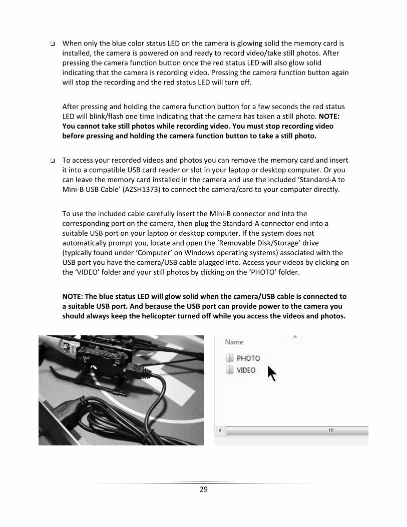
To access your recorded videos and photos you can remove the memory card and insert it into a compatible USB card reader or slot in your laptop or desktop computer. Or you can leave the memory card installed in the camera and use the included ‘Standard‐A to Mini‐B USB Cable’ (AZSH1373) to connect the camera/card to your computer directly.
To use the included cable carefully insert the Mini‐B connector end into the corresponding port on the camera, then plug the Standard‐A connector end into a suitable USB port on your laptop or desktop computer. If the system does not automatically prompt you, locate and open the ‘Removable Disk/Storage’ drive (typically found under ‘Computer’ on Windows operating systems) associated with the USB port you have the camera/USB cable plugged into. Access your videos by clicking on the ‘VIDEO’ folder and your still photos by clicking on the ‘PHOTO’ folder.
NOTE: The blue status LED will glow solid when the camera/USB cable is connected to a suitable USB port. And because the USB port can provide power to the camera you should always keep the helicopter turned off while you access the videos and photos.

30
Binding/linking is the process of programming the receiver in the control unit to recognize the Globally Unique Identifier (GUID) code of a single specific transmitter.
The Chronos CX 100 features user‐friendly technology that automatically binds/links the receiver to the transmitter by simply turning the transmitter on first then turning the helicopter on within 20 seconds (please see the ‘Control Unit Initialization and Arming’ section of this manual for more information).
30-Day Limited Warranty Term Period:We warranty that the Product(s) purchased (the “Product”) will be free from defects in materials and work¬manship when the product is new (before being used) for the limited warranty term period, 30 days, from the date of purchase by the Purchaser.
If you believe a defect in material, workmanship, etc. was not apparent when the Product was new and only became evident after the Product was used, take the following steps. If you purchased the Product at a HobbyTown store, please contact your local HobbyTown store for warranty support and/or service. If you purchased the Product from the Firelands website, use the contact information found under the Support heading to contact Firelands directly.
If you contact Firelands, you may be asked to send the product to Firelands, at your cost, for inspection. Provided the warranty conditions have been met within the warranty term period, the components that are found to be defective, incorrectly manufactured or assembled may be repaired or replaced, at the sole discretion of Firelands. Your warranty item will be returned to you at Firelands’ expense. In the event your product needs repair or a replacement part that is not covered by this warranty, your local HobbyTown store or Firelands can assist you with support and in obtaining the genuine replacement parts to repair your Prod¬uct. Firelands will charge $40.00 per hour plus the cost of replacement parts to service your vehicle if after contacting you, you so authorize such repairs. Your product will be returned to you at your expense.
If you purchased your Product from a HobbyTown Internet site not affiliated with a local store, please consult that site for its support and service policies. You can also find more information at
www.Hobbytown.com., by emailing [email protected] or call 800-205-6773
Transmitter and Receiver Binding/Linking
Warranty, Support and Service

31
Item Number Description
AZSC104CDUSB 104CD 1‐Cell/1S 3.7V LiPo, 0.4A Dual Port DC USB Charger, Ultra‐Micro Connector
AZSH1353 Ultra‐Micro Male to Male Connector Adapter Lead
AZSH1354 Micro A Female Connector to Ultra‐Micro Male Connector Adapter Lead
AZSH1355 250mAh 1‐Cell/1S 3.7V 15C LiPo Battery, Micro A Connector: Chronos CX 100
AZSH1356 4‐in‐1 Control Unit, Rx/ESCs/Mixer/Gyro: Chronos CX 100
AZSH1358M2 Micro 4‐Channel LP CX Helicopter Transmitter, Mode 2: Chronos CX 100
AZSH1359 Main Motor with Pinion Gear: Chronos CX 100
AZSH1360 Main Gear and Inner Shaft Set: Chronos CX 100
AZSH1361 Inner Shaft Bushing (2pcs): Chronos CX 100
AZSH1362 Upper and Lower Rotor Head Set: Chronos CX 100
AZSH1363 Stabilizer Flybar: Chronos CX 100
AZSH1364 Stabilizer Flybar/Upper Main Rotor Blade Linkage (2pcs): Chronos CX 100
AZSH1365 Upper and Lower Main Rotor Blade Set (1 pair each): Chronos CX 100
AZSH1366 Main Frame and Landing Gear/Skid Set: Chronos CX 100
AZSH1367 Canopy Mounts (2pcs): Chronos CX 100
AZSH1368 Hardware/Screw Set: Chronos CX 100
AZSH1369B Tail Boom, Fins and Motor Set, Blue: Chronos CX 100
AZSH1369R Tail Boom, Fins and Motor Set, Red: Chronos CX 100
AZSH1370 Tail Rotor Blade/Propeller (4pcs): Chronos CX 100
AZSH1371B Canopy with LED, Blue: Chronos CX 100
AZSH1371R Canopy with LED, Red: Chronos CX 100
AZSH1372 Camera (Video/Still) w/2GB MicroSD Memory Card and USB Cable: Chronos CX 100
AZSH1373 Standard‐A to Mini‐B USB Cable for Camera: Chronos CX 100
Replacement Parts List
32
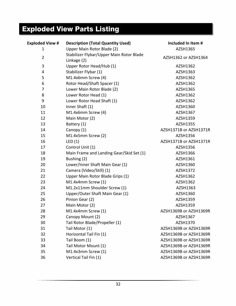
Exploded View # Description (Total Quantity Used) Included In Item # 1 Upper Main Rotor Blade (2) AZSH1365
2 Stabilizer Flybar/Upper Main Rotor Blade Linkage (2)
AZSH1362 or AZSH1364
3 Upper Rotor Head/Hub (1) AZSH1362 4 Stabilizer Flybar (1) AZSH1363 5 M1.4x6mm Screw (4) AZSH1362 6 Rotor Head/Shaft Spacer (1) AZSH1362 7 Lower Main Rotor Blade (2) AZSH1365 8 Lower Rotor Head (1) AZSH1362 9 Lower Rotor Head Shaft (1) AZSH1362 10 Inner Shaft (1) AZSH1360 11 M1.4x6mm Screw (4) AZSH1367 12 Main Motor (2) AZSH1359 13 Battery (1) AZSH1355 14 Canopy (1) AZSH1371B or AZSH1371R 15 M1.4x5mm Screw (2) AZSH1356 16 LED (1) AZSH1371B or AZSH1371R 17 Control Unit (1) AZSH1356 18 Main Frame and Landing Gear/Skid Set (1) AZSH1366 19 Bushing (2) AZSH1361 20 Lower/Inner Shaft Main Gear (1) AZSH1360 21 Camera (Video/Still) (1) AZSH1372 22 Upper Main Rotor Blade Grips (1) AZSH1362 23 M1.4x4mm Screw (1) AZSH1362 24 M1.2x11mm Shoulder Screw (1) AZSH1363 25 Upper/Outer Shaft Main Gear (1) AZSH1360 26 Pinion Gear (2) AZSH1359 27 Main Motor (2) AZSH1359 28 M1.4x4mm Screw (1) AZSH1369B or AZSH1369R 29 Canopy Mount (2) AZSH1367 30 Tail Rotor Blade/Propeller (1) AZSH1370 31 Tail Motor (1) AZSH1369B or AZSH1369R 32 Horizontal Tail Fin (1) AZSH1369B or AZSH1369R 33 Tail Boom (1) AZSH1369B or AZSH1369R 34 Tail Motor Mount (1) AZSH1369B or AZSH1369R 35 M1.4x3mm Screw (1) AZSH1369B or AZSH1369R 36 Vertical Tail Fin (1) AZSH1369B or AZSH1369R
Exploded View Parts Listing

33
Exploded View

34
____________________________________________________________________________________________________________________________________________________________________________________________________________________________________________________________________________________________________________________________________________________________________________________________________________________________________________________________________________________________________________________________________________________________________________________________________________________________________________________________________________________________________________________________________________________________________________________________________________________________________________________________________________________________________________________________________________________________________________________________________________________________________________________________________________________________________________________________________________________________________________________________________________________________________________________________________________________________________________________________________________________________________________________________________________________________________________________________________________________________________________________________________________________________________________________________________________________________________________________________________________________________________________________________________________________________________________________________________________________________________________________________________________________________________________________________________________________________________________________________________________________________________________________________________________________________________________________________________________________________________________________________________________________________________________________________________________________________________________________________________________________________________________________________________________________________________________________________________________________________________________________________________________________________________________________________________________ ____________________________________________________________________________ ____________________________________________________________________________ ____________________________________________________________________________ ____________________________________________________________________________
Notes

35
____________________________________________________________________________________________________________________________________________________________________________________________________________________________________________________________________________________________________________________________________________________________________________________________________________________________________________________________________________________________________________________________________________________________________________________________________________________________________________________________________________________________________________________________________________________________________________________________________________________________________________________________________________________________________________________________________________________________________________________________________________________________________________________________________________________________________________________________________________________________________________________________________________________________________________________________________________________________________________________________________________________________________________________________________________________________________________________________________________________________________________________________________________________________________________________________________________________________________________________________________________________________________________________________________________________________________________________________________________________________________________________________________________________________________________________________________________________________________________________________________________________________________________________________________________________________________________________________________________________________________________________________________________________________________________________________________________________________________________________________________________________________________________________________________________________________________________________________________________________________________________________________________________________________________________________________________________ ____________________________________________________________________________ ____________________________________________________________________________ ____________________________________________________________________________ ____________________________________________________________________________
Notes