ares gamma 370 rtf and rfr instruction manual...
TRANSCRIPT

1
Wingspan: 38.6 in (980mm) Length: 30.6 in (775mm) Weight with Battery: 16.0 oz (455g) Battery: 1000mAh 2S 7.4V LiPo (included with RTF, required for RFR) Charger: DC 2S 7.4V LiPo Balancing and AC adapter (included with
RTF, required for RFR) Transmitter: 6‐channel 2.4GHz (included with RTF, required for RFR) On‐Board Electronics: Receiver (installed in RTF, required for RFR), ESC and
2 servos (installed in RTF and RFR)
Specifications
Instruction Manual

2
Specifications ...................................................................................................................................... 1
Safety Precautions and Warnings ............................................................................................................. 3
FCC Information ........................................................................................................................................ 4
Gamma 370 RTF (Ready‐To‐Fly) Contents ................................................................................................ 5
Gamma 370 RFR (Ready‐For‐Receiver) Contents ..................................................................................... 5
Required to Complete............................................................................................................................... 6
Installing the Receiver (For RFR Version Only) ......................................................................................... 6
Before the First Flight Checklist (RTF Version Only) ................................................................................. 7
LiPo Battery Warnings and Usage Guidelines .......................................................................................... 8
Charging the LiPo Flight Battery ............................................................................................................. 10
Assembling the Wing .............................................................................................................................. 13
Installing the Horizontal and Vertical Tails ............................................................................................. 15
Installing the Landing Gear ..................................................................................................................... 16
Transmitter Details ................................................................................................................................. 17
Installing the Transmitter Batteries ........................................................................................................ 18
Installing the LiPo Flight Battery ............................................................................................................. 19
Centering the Control Surfaces .............................................................................................................. 20
Installing the Propeller/Prop Saver ........................................................................................................ 23
Attaching the Wing ................................................................................................................................. 27
Flight Controls and Trimming ................................................................................................................. 29
Selecting a Flying Area and Flying Conditions ........................................................................................ 32
ESC (Electronic Speed Control) Arming .................................................................................................. 33
Flight Checklist ........................................................................................................................................ 34
Flying ....................................................................................................................................................... 35
Transmitter and Receiver Binding/Linking ............................................................................................. 38
Optional Brushless Power System .......................................................................................................... 38
Optional Aileron (Aerobatic) Wing Set ................................................................................................... 45
Repairs .................................................................................................................................................... 51
Replacement Parts List ........................................................................................................................... 52
Warranty, Support and Service .............................................................................................................. 53
AMA National Model Aircraft Safety Code ............................................................................................. 53
Table of Contents

3
The Ares™ [air‐eez] Gamma 370 offers stability and durability perfect for first‐time pilots while also delivering the smooth and capable flight performance experienced sport flyers will enjoy. The advanced EPO foam airframe design is not only lightweight, durable and easy to repair, it also arrives factory‐assembled and nearly ready‐to‐fly right out of the box so you can be flying at a local park, schoolyard or flying field in almost no time at all. Also, unlike other similar class models that require significant modifications and expense to upgrade to brushless power systems or aileron control, the Gamma 370 is designed so it’s ready for both. The very affordable Brushless Power System Upgrade Combo (AZS1227) includes a brushless ESC plus a powerful 370 brushless motor and mount that install easily in minutes. And for full 4‐channel control and aerobatic capability the optional aileron‐equipped wing set (AZS1226) can be mounted in place of the standard wing without the need for any modifications. The Gamma 370 is available in RTF (Ready‐To‐Fly) and RFR (Ready‐For Receiver) versions that include a factory‐installed 370‐motor equipped power system, ESC and 9‐gram sub‐micro servos. The RFR version is ready for you to install a receiver compatible with your favorite transmitter while the RTF version includes everything needed to fly right out of the box. From AA batteries for the 6‐channel 2.4GHz transmitter and a 6‐channel receiver to the 1000mAh 2S 7.4V LiPo battery, DC balancing charger and AC adapter there’s nothing extra to buy!
And although the Gamma 370 is nearly ready‐to‐fly right out the box, please take the time to read through this manual for information about battery safety and charging, control checks and more before making your first flight. Please also visit our web site at www.Ares‐RC.com for additional information including product updates, bulletins, videos and more. Failure to use this product in the intended manner as described in the following instructions can result in damage and/or personal injury. A Radio Controlled (RC) airplane/helicopter is not a toy! If misused it can cause serious bodily harm and damage to property. Keep items that could become entangled in the propeller/rotor blades away from the propeller/rotor, including loose clothing, tools, etc. Be especially sure to keep your hands, face and other parts of your body away from the propeller/rotor blades.
Introduction
Safety Precautions and Warnings

4
As the user of this product you are solely and wholly responsible for operating it in a manner that does not endanger yourself and others or result in damage to the product or the property of others. This model is controlled by a radio signal that is subject to possible interference from a variety of sources outside your control. This interference can cause momentary loss of control so it is advisable to always keep a safe distance from objects and people in all directions around your model as this will help to avoid collisions and/or injury.
• Never operate your model if the voltage of the batteries in the transmitter is too low. • Always operate your model in an open area away from obstacles, people, vehicles,
buildings, etc. • Carefully follow the directions and warnings for this and any optional support
equipment (chargers, rechargeable batteries, etc.). • Keep all chemicals, small parts and all electronic components out of the reach of
children. • Moisture causes damage to electronic components. Avoid water exposure to all
electronic components, parts, etc. not specifically designed and protected for use in water.
• Never lick or place any portion of your model in your mouth as it could cause serious injury or even death.
This device complies with part 15 of the FCC rules. Operation is subject to the following two conditions: (1) This device may not cause harmful interference, and (2) this device must accept any interference received, including interference that may cause undesired operation. Caution: Changes or modifications not expressly approved by the party responsible for compliance could void the user’s authority to operate the equipment. This product contains a radio transmitter with wireless technology which has been tested and found to be compliant with the applicable regulations governing a radio transmitter in the 2.400GHz to 2.4835GHz frequency range. The associated regulatory agencies of the following countries recognize the noted certifications for this product as authorized for sale and use: USA
FCC Information

5
Item Description
Not Available Separately .... Gamma 370 RTF Airframe AZS1208AMD2 ................... 6HPA 6‐Channel HP Airplane Transmitter, Mode 2 Not Available Separately .... AA Batteries (8) AZSB10002S20T ................. 1000mAh 2‐Cell/2S 7.4V 20C LiPo Battery, Tamiya Connector AZSC205C ........................... 205C 2‐Cell/2S 7.4V LiPo, 0.5A DC Balancing Charger AZSC1205PS ....................... 1205PS 100‐120V AC to 12V DC Adapter, 0.5‐Amp Power Supply
Item Description
Not Available Separately .... Gamma 370 RFR Airframe
Gamma 370 RTF (Ready-To-Fly) Contents
Gamma 370 RFR (Ready-For-Receiver) Contents
6
The Gamma 370 RTF (Ready‐To‐Fly) version includes everything needed to fly right out of the box. There’s nothing extra to buy or provide! The Gamma 370 RFR (Ready‐For‐Receiver) version requires the following items:
3+ channel transmitter (with suitable range for a ‘park flyer’ class model)
3+ channel receiver (compatible with the transmitter that will be used)
2‐Cell/2S 7.4V 800–1300mAh LiPo battery (15+C continuous discharge rate capable)
LiPo battery charger (compatible with the battery that will be used)
Use the included adhesive‐backed ‘hook‐and‐loop’ material to install the receiver (not included with the RFR version) compatible with the transmitter you’ve chosen to use. Install the receiver on the side of the fuselage opposite of the ESC. Plug the 3‐wire lead from the ESC into the ‘throttle’ channel and the elevator servo lead into the ‘elevator’ channel on the receiver. NOTE: It’s important to ensure correct polarity when plugging the leads/connectors into the receiver. Refer to the markings on the receiver (or the manual for the receiver) to identify which pins accept the black color (negative/ground), red color (positive) and white color (signal) wire leads. Also, depending on the make/model of receiver it may be necessary to slightly ‘bevel’ the edges of the black color connectors so they fit easily into the case of the receiver. We recommend using a small file or sanding block and EXTREME CARE to bevel the appropriate edges of the connectors as needed. We also suggest plugging the rudder servo lead into the ‘aileron’ channel on the receiver. It’s typical to use the ‘aileron’ control stick/channel to control the rudder for ‘3‐channel’ models equipped with a rudder for primary ‘turning’ control. This helps to ensure an easier transition to controlling ‘4‐channel’ models equipped with ailerons later on.
Required to Complete
Installing the Receiver (For RFR Version Only)

7
PLEASE NOTE: This checklist is NOT intended to replace the content included in this instruction manual. Although it can be used as a quick start guide, we strongly suggest reading through this manual completely before proceeding.
Remove and inspect all contents
Begin charging the LiPo flight battery (connect it to the DC balancing charger)
Assemble/install the wing, tails and landing gear
Install the eight (8) AA batteries in the transmitter
Install the LiPo flight battery in the airplane (after it’s been fully charged)
Test the controls to confirm proper operation
Familiarize yourself with the controls
Install the propeller
Find a suitable area for flying
Before the First Flight Checklist (RTF Version Only)

8
IMPORTANT NOTE: Lithium Polymer (LiPo) batteries are significantly more volatile than the alkaline, NiCd and NiMH batteries also used in RC applications. All instructions and warnings must be followed exactly to prevent property damage and/or personal injury as mishandling of LiPo batteries can result in fire. By handling, charging or using the included LiPo battery you assume all risks associated with LiPo batteries. If you do not agree with these conditions, please return your complete product in new, unused condition to the place of purchase immediately. And although the 1000mAh 2‐Cell/2S 7.4V 20C LiPo Battery (AZSB10002S20T) included with the Gamma 370 RTF version is intended to be charged safely using the included 205C 2‐Cell/2S 7.4V LiPo, 0.5A DC Balancing Charger (AZSC205C), you must read the following safety instructions and warnings before handling, charging or using the LiPo battery.
• You must charge the LiPo battery in a safe area away from flammable materials.
• Never charge the LiPo battery unattended at any time. When charging the battery you should always remain in constant observation to monitor the charging process and react immediately to any potential problems that may occur.
• After flying/discharging the battery you must allow it to cool to ambient/room temperature before recharging. Also, it is NOT necessary or recommended to discharge the battery ‘completely’ before charging (LiPo batteries have no ‘memory’ and it’s safe to charge partially discharged batteries when using an appropriate charger and settings).
• To charge the battery you must use only the included 205C 2‐Cell/2S 7.4V LiPo, 0.5A DC Balancing Charger (AZSC205C) or a suitably compatible LiPo battery charger. Failure to do so may result in a fire causing property damage and/or personal injury. DO NOT use a NiCd or NiMH charger.
• If at any time during the charge or discharge process the battery begins to balloon or swell, discontinue charging or discharging immediately. Quickly and safely disconnect the battery then place it in a safe, open area away from flammable materials to observe it for at least 15 minutes. Continuing to charge or discharge a battery that has begun to balloon or swell can result in a fire. A battery that has ballooned or swollen even a small amount must be removed from service completely.
• Store the battery partially charged (approximately 50% charged/3.85V per cell), at room temperature (approximately 68–77° Fahrenheit [F]) and in a dry area for best results.
LiPo Battery Warnings and Usage Guidelines

9
• When transporting or temporarily storing the battery, the temperature range should be from approximately 40–100°F. Do not store the battery or model in a hot garage, car or direct sunlight whenever possible. If stored in a hot garage or car the battery can be damaged or even catch fire.
• Do not over‐discharge the LiPo flight battery. Discharging the LiPo flight battery to a voltage that is too low can cause damage to the battery resulting in reduced power, flight duration or failure of the battery entirely.
LiPo cells should not be discharged to below 3.0V each under load. In the case of the 2‐Cell/2S 7.4V LiPo battery used to power the Gamma 370 you will not want to allow the battery to fall below 6.0V during flight.
The included 20‐Amp Brushed Motor ESC (AZS1210) features a ‘soft’ low voltage cutoff (LVC) that smoothly reduces power to the motor (regardless of the power level you have set with the left‐hand/throttle stick) to let you know the voltage of the battery is close to the 6.0V minimum. However, even before this reduction in power, if you find that more than the typical amount of throttle/power is required to cruise or climb you should land the model and disconnect the battery immediately to prevent over‐discharge.
And while it is possible to continue flying the model after the soft LVC occurs, this is NOT recommended. Continued discharging can result in reaching the 5.0V ‘hard’ LVC which may cause permanent damage to the LiPo battery resulting in reduced power and flight duration during subsequent fights (or failure of the battery entirely which is not covered under warranty).
Also, it is not recommended that you fly to the soft LVC every time you fly. Instead you should be aware of the power level of the battery/airplane throughout the flight, and if at any time the airplane begins to require more throttle/power than typical to maintain cruise or climb you should land the airplane and disconnect the LiPo battery immediately. Constantly discharging the battery to the soft LVC can still cause permanent damage to the battery so it’s best to use a timer or stop‐watch to time the duration of your flights and to stop flying at a reasonable time before the soft LVC is reached.
IMPORTANT NOTE: DO NOT LEAVE THE LIPO BATTERY CONNECTED TO THE ESC UNLESS YOU ARE READY TO FLY. IF THE BATTERY IS LEFT CONNECTED TO THE ESC WHEN IT IS NOT IN USE THE LIPO BATTERY WILL BE OVER‐DISCHARGED BY THE

10
SMALL AMOUNT OF CURRENT THE ESC CONSUMES. It can sometimes take a few hours or even up to a few days to over‐discharge the battery this way but doing so will likely cause permanent damage to or failure of the battery entirely (which is not covered under warranty).
For the Gamma 370 RTF version you must charge the included 1000mAh 2‐Cell/2S 7.4V 20C LiPo Battery (AZSB10002S20T) using only the included 205C 2‐Cell/2S 7.4V LiPo, 0.5A DC Balancing Charger (AZSC205C) or a suitably compatible LiPo battery charger. Charging the LiPo battery using a non‐LiPo battery compatible charger (such as a NiCd or NiMH battery charger), or even a different LiPo battery charger with the incorrect settings, may result in damage to the battery or even fire resulting in property damage and/or personal injury.
Please follow these steps to charge the LiPo flight battery with the included charger:
Plug the included 1205PS 100‐120V AC to 12V DC Adapter, 0.5‐Amp Power Supply (AZSC1205PS) into a compatible 100‐120V AC outlet then connect the power output lead to the receptacle on the side of the 205C charger (NOTE: The 1205PS adapter/power supply is packed safely on the BOTTOM side of the foam insert inside the box). The adapter/power supply and charger are powered on when the red color LED indicator is glowing.
PLACE THE 205C CHARGER ON A FLAT, SMOOTH AND HEAT‐RESISTANT SURFACE.
It’s important that air is able to circulate through the charger during the charging process in order to keep it from over‐heating. It’s especially important that the vent openings on the bottom and sides of the charger are not blocked. DO NOT place the charger on carpeted or other similar surfaces that may block the vent openings. Also, DO NOT place the charger in direct sunlight before, during or after use.
Charging the LiPo Flight Battery

11
Connect the white 3‐pin connector from battery (also typically referred to as the ‘balance connector’) to the mating connector on the charger. YOU MUST BE CAREFUL TO ENSURE PROPER POLARITY BEFORE MAKING THE CONNECTION. This is accomplished by ensuring the black color negative/ground wire lead is oriented so it’s toward the right‐hand side of the charger when looking at the charger from above. And while the white connectors are ‘keyed’ to minimize the risk of a reverse polarity connection, if you force them it is possible to make connection with the incorrect polarity potentially causing damage to the battery and/or charger. When the connectors are properly aligned for correct polarity, connecting them should require only a moderate amount of pressure to achieve the ‘click’ that indicates a secure connection.
When the battery is connected to the charger securely and with the proper polarity both the red color and green color LED indicators will glow. The battery will be charging anytime the green LED indicator is glowing.
It will take approximately 1.5–2.5 hours to fully charge a mostly or fully discharged (not over‐discharged) battery (NOTE: See the following information in this section for more details regarding optional ‘fast’ charging that can reduce charge times to as little as 30‐45 minutes). And when the battery is fully charged the green LED indicator will stop glowing entirely. When the green LED indicator is no longer glowing you can disconnect the battery from the charger as it is now fully charged and ready for use.
NOTE: The LiPo battery included with your new model will arrive partially charged. For this reason the initial charge may only take approximately 1 hour.

12
IMPORTANT NOTE: DO NOT STORE THE LIPO FLIGHT BATTERY FULLY CHARGED. For improved safety and longevity of the LiPo battery it’s best to store it only partially charged for any length of time. Storing the LiPo battery at approximately 50% charged (which is approximately 3.85V per cell) is typically best, however it will take some careful management of the charge time and the use of a volt meter to achieve this voltage. If you have the equipment and skills to achieve the 50% charge level for storage it is recommended. If not, simply be sure to not store the battery fully charged whenever possible. In fact, as long as the battery will be stored at approximately room temperature and for no more than a few weeks before the next use, it may be best to store the battery in the discharged state after the last flight (as long as the battery was not over‐discharged on the last flight). Optional ‘Fast’ Charging The included 1000mAh 2‐Cell/2S 7.4V 20C LiPo Battery (AZSB10002S20T) can be ‘fast’ charged at rates up to 2C (2x the Capacity of the battery; 2 x 1000mAh = 2000mAh = 2.0A) when using approved and compatible LiPo battery chargers. It will take approximately 30‐45 minutes to fully charge a mostly or fully discharged (not over‐discharged) battery when charging at 2C. For ‘fast’ charging we recommend using the Radient™ Primal or Ascend chargers. Both chargers are capable of charging the included LiPo battery at rates up to 2C/2.0A and can also be used to charge other higher and lower capacity LiPo, NiCd and NiMH batteries. Both chargers also include connectors compatible with the ‘Tamiya‐style’ and JST‐XH (balance) connectors installed on the included LiPo battery and can be powered from a 100–240V AC outlet. The Ascend charger can also be powered from a 12–15V DC power source, such as a 12V ‘car’ battery, for quick and convenient charging at the field or beyond. You can find the Radient Primal and Ascend chargers at HobbyTown USA® stores and www.HobbyTown.com.

13
Parts/Tools Required:
Left and right wing panels
Plastic wing cover
Thin two‐sided tape (optional)
5–15 minute epoxy (optional)
To assemble the wing start by sliding the plywood ‘joiner’ that extends out of the right wing panel into the corresponding slot in the left wing panel. Carefully slide the panels together until they meet. OPTIONAL: For a more secure wing joint you can use thin two‐sided tape or 5–15 minute epoxy between the panels. Thick cyanoacrylate (CA) glue may also be used keeping in mind that the use of glue/epoxy will result in a more ‘permanent’ wing joint. Also, it’s important to ensure that the top and bottom sides of the wing panels are aligned properly, especially near the leading (front) and trailing (rear) edges, when joining the panels with tape or glue/epoxy. NOTE: Due to slight variations in the production of related parts it’s possible that the leading (front) and trailing (rear) edges of both wing panels will not align exactly when the panels are slid together. This OK and should have no discernible impact on the flight performance/characteristics of the model.
After sliding/joining the two wing panels together locate the plastic ‘wing cover’. This cover helps protect the top of the wing from the rubber bands used to attach it to the fuselage while also providing additional support for the wing joint. Before removing the backing material on the tape used to secure the cover to the wing check the fit of the cover on the wing. Line up the trailing (rear) edge of the cover with the trailing edge of the wing while also ‘centering’ the cover over the joint between the wing panels
Assembling the Wing

14
After confirming the cover fits correctly remove the backing material to expose the tape. Then, very carefully line up the trailing edge of the cover with the trailing edge of the wing and center the cover before pressing it down against the wing panels. Start from the trailing edge of the wing and slowly press the cover down with light pressure so it fits against the wing as closely as possible until you reach the leading (front) edge. Apply only light pressure so you can possibly remove and reinstall the cover if the fit/alignment is not correct. Then, after confirming the fit and alignment are good, apply more pressure to better secure the cover to the wing.
NOTE: In some cases it may not be possible for all edges of the cover to fit flush against the surface of the wing. This is not typically a problem as the rubber bands used to attach the wing to the fuselage will help hold the edges of the cover in place. However, depending on the fit of some parts it may be helpful to apply transparent ‘packing’ tape and/or cyanoacrylate (CA) glue (we recommend Medium/Gap‐Filling or Thick viscosity) to better secure the edges. However, keep in mind that the use of glue will result in a more ‘permanent’ installation of the wing cover.
The wing is now assembled and ready to attach to the fuselage in a later step.
15
Parts/Tools Required:
Fuselage
Horizontal and vertical tails
Plastic tail mount
2 x 8mm ‘button’ (small) head screw; 2pcs
2 x 8mm ‘pan’ (large) head screw; 1pc
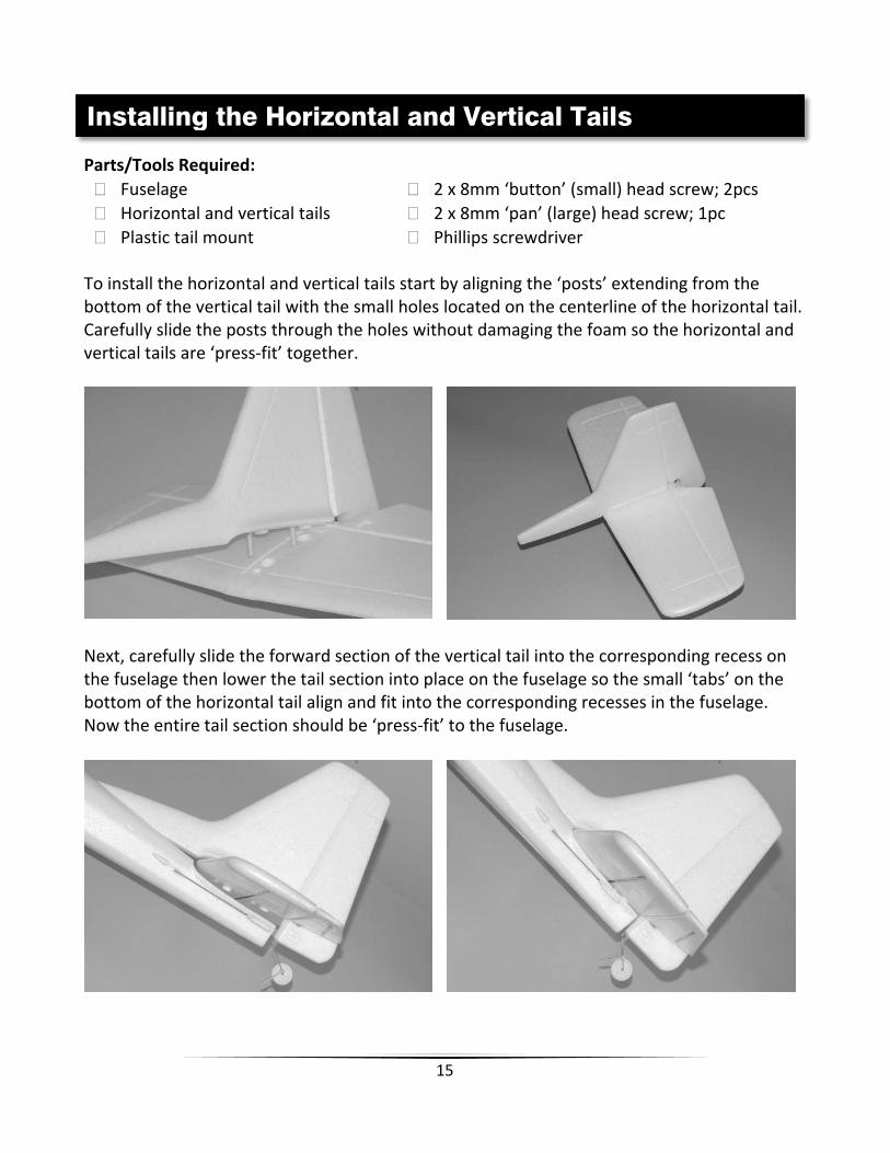
Phillips screwdriver To install the horizontal and vertical tails start by aligning the ‘posts’ extending from the bottom of the vertical tail with the small holes located on the centerline of the horizontal tail. Carefully slide the posts through the holes without damaging the foam so the horizontal and vertical tails are ‘press‐fit’ together.
Next, carefully slide the forward section of the vertical tail into the corresponding recess on the fuselage then lower the tail section into place on the fuselage so the small ‘tabs’ on the bottom of the horizontal tail align and fit into the corresponding recesses in the fuselage. Now the entire tail section should be ‘press‐fit’ to the fuselage.
Installing the Horizontal and Vertical Tails

16
Before installing the plastic tail mount be sure to align and place the tail wheel bracket/mount into the corresponding recess in the bottom of the fuselage. Then, carefully slide the posts extending from the tail mount into the holes in the fuselage. The posts extending from the tail mount must engage the posts that extend from the bottom of the vertical tail while also ‘capturing’ the tabs on the tail wheel bracket/mount. Take your time and carefully adjust the position of the tail section, tail wheel bracket/mount and tail mount until both posts and the tail wheel bracket/mount engage properly.
When engaged properly the tail mount should fit almost flush against the bottom of the fuselage. Now you can slide the two 2 x 8mm ‘button’ (small) head screws into the recessed openings in the mount and tighten them securely. Be careful when tightening these screws because tightening them too much can strip/break the plastic posts and/or damage the tails/fuselage. To complete the installation use the remaining 2 x 8mm ‘pan’ (large) head screw to secure the tail wheel bracket/mount in place.
Parts/Tools Required:
Main Landing Gear Assembly
Plastic Landing Gear Cover
2 x 8mm ‘button’ (small) head screw; 2pcs
Phillips screwdriver
The main landing gear is installed in the slot/opening located in the ‘Landing Gear Mount/Battery Hatch’ on the bottom of the fuselage. Use moderate pressure to ‘squeeze’ the landing gear legs together slightly then slide the landing gear into the slot (you can also remove the landing gear by doing the same). Be sure the landing gear is installed so it angles forward when viewing the airplane directly from the side.
Installing the Landing Gear

17
Slide the plastic landing gear cover into the slot/over the landing gear and carefully align the small pins on the cover with the holes in the mount. Press the cover into to place so it’s approximately flush with the mount/hatch then use two 2 x 8mm ‘button’ (small) head screws to secure the cover and landing gear in place.
The Gamma 370 RTF version includes a 6HPA 6‐Channel HP Airplane Transmitter equipped with 2.4GHz technology, trim levers, servo reversing switches and optional‐use ‘delta/elevon’ mixing (the RFR version requires a 3+ channel transmitter/receiver).
IMPORTANT NOTE: As is typical of most ‘3‐channel’ models that are equipped with a rudder for primary ‘turning’ control, the ‘aileron’ control stick/channel is used to control the rudder on the Gamma 370. This helps to ensure an easier transition to controlling ‘4‐channel’ models equipped with ailerons later on.
Transmitter Details

18
Low Battery Voltage/Power Indication When the AA battery voltage/power drops to a level that’s too low for safe continued operation, the red color LED indicator will begin flashing. DO NOT use the transmitter or fly when the red LED indicator is flashing and immediately install new AA batteries before using the transmitter or flying.
Antenna Position/Orientation The RF output signals transmit best/strongest from the shaft of the antenna rather than from the tip. As a result you should never point the tip of the antenna directly at the model. Also, the transmitter antenna can be rotated up to 180° and folded up to 90° so be sure to hold the transmitter and position the antenna as needed to ensure the best possible signal transmission.
Control/Servo Reversing The 6HPA transmitter features control/servo reversing functionality for the aileron, elevator, throttle and rudder channels. The control/servo directions were set correctly at the factory for the Gamma 370 RTF, however, in case the controls are operating in the wrong direction, or you use the electronics in other models later on, simply change the position of ‘Servo Reverse’ switch for the channel(s) as needed.
Delta/Elevon Mixing Located to the right of the ‘Servo Reverse’ switches is a switch that activates/deactivates the optional‐use ‘Delta/Elevon’ mixing. No such mixing is used for the Gamma 370 so please be sure this switch is in the OFF/lower position (failure to do so will result in improper control and the inability to fly the Gamma 370). However, if using this transmitter with ‘flying wing’, delta or other airplanes that ‘combine (mix)’ the elevator and aileron (often known as ‘elevon’) controls you can move the switch to the ON/upper position.
Install the eight (8) included AA batteries in the back of the transmitter by first removing the battery compartment cover/door. Ensure proper polarity of the batteries before installing them as noted by the markings molded into the battery compartment, then re‐install the compartment cover/door.
Check for proper operation of the transmitter by switching the power switch ON (slide it upward). The ‘POWER’ LED indicator should begin to glow solid green (indicating the transmitter is powered on) and the ‘RF OUTPUT’ LED indicator should begin to glow solid red shortly after (indicating the transmitter is outputting an RF signal). These indications confirm the transmitter is powered on and functioning correctly.
Installing the Transmitter Batteries

19
IMPORTANT NOTE: You must ALWAYS turn the transmitter on first AND have the left‐hand/throttle stick in the lowest possible position BEFORE connecting/installing the LiPo flight battery. And before proceeding with the following steps, please be sure the transmitter is powered on and the left‐hand/throttle stick is in the lowest possible position.
After the LiPo battery has been fully charged it’s ready to be installed in the airplane. To access the battery compartment on the bottom of the airplane, rotate the two latches until they’re out of the way of the hatch cover then remove the cover.
The LiPo flight battery will be secured inside the airplane using ‘hook‐and‐loop’ material. Use the included adhesive‐backed hook‐and‐loop material and apply the appropriate side inside the battery compartment and/or on the side of the battery opposite of the label.
Before installing the battery in the airplane you’ll need to connect it to the ESC (Electronic Speed Control). YOU MUST BE CAREFUL TO ENSURE PROPER POLARITY BEFORE CONNECTING THE BATTERY TO THE ESC. By orienting/aligning the wire leads of the battery and ESC so they’re ‘red to red’ and ‘black to black’ you’ll be able to make the connection with correct polarity.
Also, although the ‘Tamiya‐style’ connectors are ‘keyed’ to minimize the risk of a reverse polarity connection, if you force them it may be possible to make connection with incorrect polarity potentially causing damage to the ESC and/or battery. When the connectors are properly aligned for correct polarity, connecting the Tamiya‐style connectors should require only a minimal amount of pressure to achieve the light ‘click’ that indicates secure connection.
Installing the LiPo Flight Battery

20
After the LiPo battery is connected to the ESC you can insert it into the battery compartment then secure it with the hook‐and‐loop material. Carefully ‘tuck’ the wire leads and connectors inside the compartment ensuring they do not damage the battery or foam airframe while also allowing the hatch cover to be installed over the compartment opening. When the hatch cover is properly aligned and installed rotate the two latches until they secure the cover in place.
To remove the LiPo flight battery first remove the hatch cover and pull the wire leads and connectors out of the battery compartment. Then, carefully pull the battery out of the compartment by separating the hook‐and‐loop material mounted inside the fuselage and on the battery. To disconnect the battery from the ESC gently press down on the back of the latch molded into the male connector from the ESC so it disengages the female connector from the battery and then pull the connectors apart. DO NOT power off the transmitter until the LiPo flight battery is removed from the airplane and disconnected from the ESC. REMEMBER: The transmitter is always ON FIRST and always OFF LAST!
With the transmitter turned on and the LiPo flight battery connected to the ESC (and installed in the battery compartment) it’s now possible to connect the pushrods to the rudder and elevator control surfaces and to ‘center’ the surfaces accordingly.
First, be sure to center the elevator and rudder (aileron) trim levers. See the ‘Transmitter Details’ and ‘Flight Controls and Trimming’ sections of this manual for more information on the trim levers and their functions.
Centering the Control Surfaces

21
With the trim levers centered, carefully spread open each ‘clevis’ (the white color plastic part installed on the threaded end of the metal pushrod) so you can insert the pin in the OUTERMOST hole on each control horn. It may be helpful to insert a flat blade screwdriver (not included) into the clevis then carefully ‘twist’ it until it disengages the pin from the hole in the clevis. Also, it is not necessary to ‘snap’ the clevis back together until the centering adjustments are complete.
After connecting the clevises to the control horns view the vertical tail and rudder from directly above. The rudder should be ‘in line’ with the vertical tail when it’s properly ‘centered’. However, if the rudder is angled off to the right or left you can adjust the length/position of the pushrod/clevis so the surface is centered ‘mechanically’ while the trim lever on the transmitter is centered.
If the rudder is angled off to the left carefully remove the clevis from the control horn and screw it ‘in’ (clockwise) one half to one full turn then insert the pin back into the outermost hole in the control horn. Or, if the rudder is angled off to the right carefully remove the clevis from the control horn and screw it ‘out’ (counter‐clockwise) one half

22
to one full turn then insert the pin back into the outermost hole in the control horn. View the vertical tail and rudder from directly above again and continue adjusting the length/position of the pushrod/clevis until the rudder is centered appropriately.
NOTE: You should always rotate the clevis until the pin is perpendicular with the control horn to ensure the pin is not under any excessive load/pressure when inserted in the hole and during operation. In some cases it may not be possible to ‘exactly’ center the surface mechanically while properly aligning the pin. In these cases be sure the pin is properly aligned then adjust the position of the trim lever slightly as needed. Also, it will likely be necessary to make further adjustments to the position of the trim lever during flight as most surfaces do not end up in exactly the centered position when an airplane is trimmed properly for actual flight (but ‘centered’ is still the best starting point).
Follow the same steps outlined for centering the rudder to center the elevator as well.
Also, we strongly recommend installing the included ‘clevis keepers’ to provide added security for the clevises. Typically you can carefully slide the keepers over the clevises when they are not connected to the control horn. Then, after connecting the clevis to the control horn and ‘snapping’ the clevis together you can slide the keepers into a position that does not allow them to ‘bind’ against the control horn during movement of the surface.

23
IMPORTANT NOTE: Before installing the propeller you MUST disconnect the battery from the ESC. Failure to do so can result in serious bodily harm and/or damage to property!
There are two options available for installing the propeller on the Gamma 370. The first option is for ‘standard’ installation of the propeller and spinner while the second option is for installation of the ‘prop saver’. We recommend that first‐time and low‐time pilots install the prop saver as it helps to protect the propeller and gearbox propeller shaft from damage during some less than perfect takeoffs and landings.
IMPORTANT NOTE: The propeller must be installed in the correct direction in order for the airplane to fly! The front of the propeller is the side that is slightly curved/rounded ‘outward’. This side of the propeller must ALWAYS face forward on the Gamma 370 for proper operation and performance.
Standard Installation
Parts/Tools Required:
Propeller
Rubber Spinner
3mm (standard) hex nut; 2pcs
3mm flat washer; 1pc
Pliers, adjustable wrench or 5.5mm socket/wrench
Installing the Propeller/Prop Saver

24
For standard installation with the spinner start by threading the first (rear) 3mm hex nut onto the threaded portion of the gearbox propeller shaft until it stops at the end of the threads. Tighten this nut in place (do not over‐tighten!) then install the propeller on the shaft and rotate it as necessary until it lines up with, slides over and fully ‘engages’ the nut. Next, install the washer and remaining (front) hex nut then tighten the nut accordingly (do not over‐tighten!).
IMPORTANT NOTE: Before installing the spinner it will be helpful to proceed to the ‘ESC (Electronic Speed Control) Arming’ section of this manual and to carefully run the motor and ensure the propeller tips are ‘tracking’ properly. Due to possible variations in the ‘hub’ of the propeller, the hex nuts and threads on the gearbox propeller shaft sometimes the propeller will be ‘angled’ slightly when installed. If the prop is angled even slightly one tip will be ‘ahead’ of the other when spinning resulting in an ‘out‐of‐track’ condition that causes significant vibration and power loss.

25
Usually it’s possible to correct the angled/out‐of‐track condition by loosening the front hex nut until you can pull the propeller forward and rotate it to the next position in which it will engage the rear hex nut. Then tighten the font hex nut and run the motor again. If the tips are still out of track repeat this process until you find the position where the propeller tips track best. Or, in very rare cases, you may need to switch to a different rear hex nut and/or propeller to ensure optimal tracking and the smoothest possible operation.
After ensuring optimal tracking you can install the rubber spinner over the exposed end of the gearbox propeller shaft. Push the spinner onto the shaft after ensuring the shaft is aligned properly with the ‘hole’ in the spinner. Also, be sure the ‘cut outs’ in the spinner align properly with the blades of the propeller the push the spinner onto the shaft until it stops. Check to be sure the back edge of the spinner does not touch the cowl, and if it does you can carefully remove some of the material along the back edge until it no longer touches.
Installation With Prop Saver
Parts/Tools Required:
Propeller
Prop Saver
Small rubber band
3mm (standard) hex nut; 3pcs
3mm flat washer; 1pc
Ruler or calipers
Pliers or adjustable wrench
Additional pliers, adjustable wrench or 5.5mm socket/wrench
IMPORTANT NOTE: The prop saver does NOT prevent all damage to the propeller or gearbox propeller shaft! However, in some cases it can help to prevent breaking the propeller, bending the gearbox propeller shaft or damaging the gearbox/motor.
For installation of the prop saver start by threading the first (rear) 3mm hex nut onto the shaft then stop when 7/16” (11mm) of the shaft extends beyond it (DO NOT thread the nut onto the shaft any further otherwise the prop saver will not function correctly!).

26
Next, insert the second hex nut into the recess in the prop adapter and slide/thread both onto the shaft, with the recess/nut toward the front of the shaft, and until the prop saver stops against the rear nut. Hold the rear nut in place with pliers or an adjustable wrench then carefully tighten the prop saver and nut against it. Install the washer and remaining (front) hex nut on the end of the shaft then use pliers or an adjustable wrench to hold the rear nut in place while using additional pliers, an adjustable wrench or 5.5mm socket/wrench to tighten the front nut (do not over‐tighten!).
Measure to be sure no more than approximately 3/32” (2.5mm) of the shaft extends beyond the front hex nut. Otherwise adjust the position of all parts as needed so no more than approximately 3/32” (2.5mm) of the shaft extends beyond the nut. This is critical to ensuring the prop saver works correctly!
To install the propeller rotate it as necessary until it lines up with, slides over and fully ‘engages’ the front hex nut in a position as close to perpendicular (when viewed from the front) with the prop saver as possible. Then use a small rubber band to attach the propeller to the prop saver. Be sure to wrap the rubber band around the propeller and prop saver enough times to keep the propeller as secure as possible (while still allowing for some limited flexibility).

27
IMPORTANT NOTE: IT’S CRITICAL THAT THE RUBBER BAND IS NOT INSTALLED TOO LOOSELY OTHERWISE THE PROPELLER WILL COME OFF THE PROP SAVER/AIRPLANE DURING FLIGHT. Also, be sure to inspect the rubber band often, especially anytime you have even a minor ‘prop strike’, and to replace it as often as needed to ensure it does not break or come loose during flight. In some cases it may be a good idea to purchase enough suitable spare rubber bands from an office supply or other appropriate store so you can replace the rubber band before each flying session.
OPTIONAL: For improved appearance and protection of the gearbox propeller shaft you can cut down/shorten the shaft accordingly. However, note that if you shorten the shaft it will not be possible to switch to standard installation of the propeller and spinner without changing to a new gearbox propeller shaft (AZS1212) first.
We recommend using a high‐speed rotary tool with a suitable cut‐off wheel/disc to cut the shaft so only approximately 1/2” (13mm) of the threaded portion remains. Then follow the previous steps to install the prop saver and propeller accordingly.
IMPORTANT NOTE: You MUST wear appropriate eye protection and use extreme care when using a high‐speed rotary tool!
Parts/Tools Required:
Assembled wing
Fuselage
Large rubber bands; 4–6pcs
The wing is attached to the fuselage of the Gamma 370 using rubber bands. This makes it quick and easy to attach when you’re ready to fly and to remove for more convenient transport/storage. Rubber brands also allow the wing to ‘shift’ slightly on the fuselage to help reduce damage in the unfortunate event of a crash or less than perfect takeoff or landing.
To attach the wing start by setting it on the ’wing saddle’ area on top of the fuselage. Align the joint between the left and right wing panels with the centerline of the fuselage at both the leading (front) and trailing (rear) edges. Hold the wing against the fuselage with one hand then use the other hand to carefully take a rubber band and pull it around one of the rear dowel posts then across the wing to the front dowel post on the OPPOSITE side of the fuselage.
Attaching the Wing
28
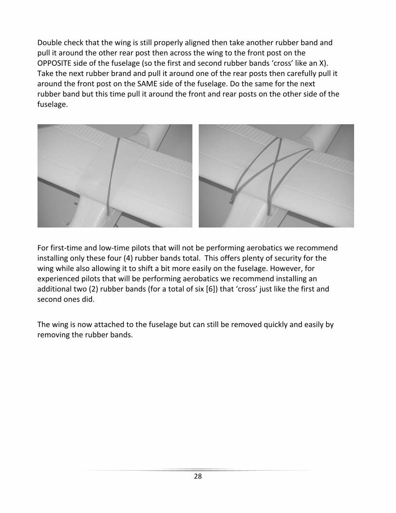
Double check that the wing is still properly aligned then take another rubber band and pull it around the other rear post then across the wing to the front post on the OPPOSITE side of the fuselage (so the first and second rubber bands ‘cross’ like an X). Take the next rubber brand and pull it around one of the rear posts then carefully pull it around the front post on the SAME side of the fuselage. Do the same for the next rubber band but this time pull it around the front and rear posts on the other side of the fuselage.
For first‐time and low‐time pilots that will not be performing aerobatics we recommend installing only these four (4) rubber bands total. This offers plenty of security for the wing while also allowing it to shift a bit more easily on the fuselage. However, for experienced pilots that will be performing aerobatics we recommend installing an additional two (2) rubber bands (for a total of six [6]) that ‘cross’ just like the first and second ones did.
The wing is now attached to the fuselage but can still be removed quickly and easily by removing the rubber bands.

29
In the event you are not familiar with the controls of your Gamma 370, please take the time to familiarize yourself with them as follows and before attempting your first flight.
The left‐hand stick on the transmitter controls the throttle. When the left‐hand stick (also known as the ‘throttle’ stick) is in the lowest possible position the motor will not run and the propeller will not spin.
Moving the stick upward will increase the speed/RPM of the propeller. Increasing the speed of the propeller increases the speed of the model and also provides the thrust needed to climb/increase altitude.
Decreasing the speed/RPM of the propeller by lowering the left‐hand stick will decrease the speed of the model and reduce thrust making it possible to descend/decrease altitude.
During flight you can adjust the throttle to a position, typically around the middle (also known as ‘half stick/power’), to maintain/cruise at a given altitude and increase flight duration.
IMPORTANT NOTE: As is typical of most ‘3‐channel’ models that are equipped with a rudder for primary ‘turning’ control, the ‘aileron’ control stick/channel is used to control the rudder on the Gamma 370. This helps to ensure an easier transition to controlling ‘4‐channel’ models equipped with ailerons later on.
Flight Controls and Trimming

30
The right‐hand stick controls both the elevator and the rudder. Pushing the stick forward/upward will lower the elevator and pitch the nose of the airplane downward to descend.
Pulling the stick backward/downward will raise the elevator and pitch the nose of the airplane upward to climb.
The elevator trim lever (located immediately to the left of the right‐hand stick) can be used to help keep the airplane from climbing or descending when in ‘cruise flight’ and with no right‐hand stick/elevator input. For example, if the airplane climbs when attempting to cruise and maintain a given altitude, add down elevator trim until the airplane flies as level as possible and maintains the desired altitude at cruise speed. Also, when you have the elevator ‘trimmed’ so the airplane maintains the desired altitude at cruise speed (typically around half stick/power) the airplane will then ‘climb’ steadily, without right stick/elevator input, at higher throttle stick positions/power settings (this is normal and preferred).

31
Moving the right‐hand stick to the left will move the rudder to the left. This will roll/turn the airplane to the left.
Moving the stick to the right will move the rudder to the right. This will roll/turn the airplane to the right.
The rudder (aileron) trim lever (located immediately below the right‐hand stick) can be used to help keep the airplane from drifting/turning left or right during flight with no right‐hand stick/rudder input. For example, if the airplane drifts to the right in flight, add left trim until the airplane flies as straight as possible without drifting. And once you’re familiar with the primary controls of the airplane you’re almost ready to fly!

32
Based on the size and weight of the Gamma 370 it’s typically considered to be a ‘park flyer’ class model. As a result it’s best to fly the Gamma 370 at a local park, schoolyard, flying field or other area that’s large enough and free of people and obstructions. We recommend an area the size of at least one football/soccer field, however, even larger areas are better suited and preferred especially when learning how to fly. DO NOT fly in parking lots, crowded neighborhood areas or in areas that are not free of people and obstructions. We also suggest flying over grass as it’s a much more forgiving surface that causes less damage in the unfortunate event of a crash. Short grass is better for takeoffs and landings as grass that is too long can cause the airplane to nose‐over/flip and be damaged. An ideal flying area allows for takeoffs and landings on a smoother surface (such as asphalt) and flying over grass. PLEASE NOTE: The Gamma 370 is designed to be flown outdoors only. Flying Conditions It’s typically best to fly on days that are calm with no wind, especially when learning how to fly. We strongly suggest flying only in calm conditions until you’re familiar with the controls and handling of the model. Even light winds can make it much more difficult to learn to fly, and in some cases can even carry the model beyond your line of sight. Also, if you are a first‐time or low‐time pilot we highly recommend allowing a more experienced pilot to test fly and properly trim the model before attempting your first flight. A proven flyable and properly trimmed model is significantly easier and more enjoyable to fly! Please contact your local hobby shop and/or flying club to find a more experienced pilot near you. After you’ve properly trimmed the airplane in calm conditions and become familiar with its handling/capabilities you’ll be able to fly in light winds, or, depending on your experience and comfort level, in winds up to 5–7 mph. DO NOT fly on days when significant moisture, such as rain or snow, is present.
Selecting a Flying Area and Flying Conditions

33
For added safety the 20‐Amp Brushed Motor ESC (AZS1210) installed in your Gamma 370 is equipped with an ‘arming’ switch/button. This checklist includes the steps you must follow to ensure safe and proper arming of the ESC:
Before each flight you must ALWAYS turn the transmitter on before connecting the LiPo flight battery to the ESC. Never connect the battery to the ESC before powering the transmitter on first. Also, after each flight you should always disconnect the battery from the ESC before powering off the transmitter.
With the transmitter powered on and the battery connected to the ESC you should have full control of the rudder and elevator servos/control surfaces. However, you will not have control of the throttle and motor, regardless of the position of the left‐hand/throttle stick, until the ESC is armed.
Also, although the ESC is not yet armed it is strongly recommended that you ALWAYS keep the left‐hand/throttle stick in the lowest possible position to ensure the motor/propeller do not spin until you are ready to fly. This is a very good habit to learn because most RC aircraft models are not equipped with an arming switch/button.
Position the airplane so you and all objects are clear of the propeller. We recommend positioning the airplane so the propeller is pointed away from you and you are able to hold on to the fuselage and/or wing securely.
Before pressing the arming button the left‐hand/throttle stick MUST be set to the lowest possible position OTHERWISE THE MOTOR/PROPELLER WILL BEGIN TO SPIN IMMEDIATELY AFTER THE BUTTON IS PRESSED!
ESC (Electronic Speed Control) Arming

34
When you’re ready to control the throttle and fly, and as long as the left‐hand/throttle stick is set to the lowest possible position, press the arming button located on the left‐side of the airplane. THE ESC WILL NOW BE ARMED SO USE EXTREME CAUTION AS THE PROPELLER WILL SPIN WHEN THE LEFT‐HAND/THROTTLE STICK IS RAISED ABOVE THE LOWEST POSSIBLE POSITION!
With all objects clear of the propeller, including in the plane of rotation and in front of it, hold on to the model securely to test operation of the throttle/power system. HOLD THE AIRPLANE SECURELY then slowly raise the left‐hand/throttle stick until it reaches the highest possible position and the power system is at ‘full power’. Then lower the stick to the lowest possible position to turn the power system off.
After confirming the ESC has armed and the power system is performing properly your Gamma 370 is ready to fly! However, please review the following section of the manual BEFORE proceeding with the first flight.
PLEASE NOTE: This checklist is NOT intended to replace the content included in this instruction manual. Although it can be used as a quick start guide, we strongly suggest reading through this manual completely before proceeding.
Always turn the transmitter on first
Plug the LiPo flight battery into the ESC and install it in the fuselage
Confirm the controls are operating properly then press the ESC arming button
Fly the model (hand‐launch or takeoff from a flat/level surface)
Land the model (land on a flat/level surface)
Unplug the LiPo flight battery from the ESC
Always turn the transmitter off last
Flight Checklist

35
Now that you’ve selected a suitable flying area and the ESC is armed, your Gamma 370 is ready to fly! And when making your first flights we suggest following these steps:
There are two ways to get the Gamma 370 into the air, the first way being to ‘hand‐launch’ the airplane. This is easy to accomplish by holding the bottom of the airplane (under the wing) in your hand with the wings level and with the nose pointed into any wind (ALWAYS HAND‐LAUNCH/TAKEOFF AND LAND WITH THE NOSE POINTED INTO ANY WIND!). Then, advance the left‐hand/throttle stick to the highest position/full power and throw’ the model forward with the nose level to or just slightly above the horizon. The airplane will be flying almost immediately after it leaves your hand allowing you to focus on keeping the wings level and the nose pointed into the wind while continuing to climb to a safe altitude.
IMPORTANT NOTE: DO NOT hand‐launch the airplane with the nose angled too high (more than 2–4 degrees) above the horizon. Also, do not attempt to climb/gain altitude with the nose of the airplane angled upward more than approximately 20–30 degrees above the horizon, or at less than full power, otherwise the airplane may lose lift, ‘stall’ and crash. This is one of the most common ways for first‐time and low‐time pilots to crash!
The second way to get the airplane into the air is to perform a Rise Off Ground (R.O.G.) takeoff from a smooth, level surface (such as asphalt or short grass). Set the airplane on the takeoff surface with the nose pointed into any wind then advance the throttle to full power. Keep the nose pointed into the wind by using rudder control, and when the airplane reaches flying speed it will slowly rise off the ground or you can pull back slightly on the right‐hand stick (‘up’ elevator) to help the model rise off the ground. And again, do not attempt to climb/gain altitude with the nose of the airplane angled more than approximately 20–30 degrees above the horizon, or at less than full power, otherwise the airplane may lose lift, stall and crash.
After hand‐launch/takeoff focus on keeping the rate of climb smooth and steady, the wings level and the nose pointed into any wind until reaching an altitude of approximately 150–250 feet high. Higher is even better as long as you can still see the airplane clearly. However, you want to be sure to keep the airplane at an altitude and distance that allows you time to react but also makes it possible to know the exact orientation of the airplane so you can always respond accordingly.
Flying

36
At the desired altitude you can level the airplane off by pushing forward slightly on the right‐hand stick (‘down’ elevator) until the airplane is flying level. Then, reduce the left‐hand/throttle stick position/power to approximately 1/2 to 2/3 for cruise flight.
You’ll find that it only takes relatively small/minor rudder inputs to change direction in flight. Remember to keep these inputs as minimal as possible as significant inputs, such as moving the stick all the way to the left or right (and holding it there), could result in over‐control, loss of orientation and/or a possible crash.
If you find the airplane constantly climbs, descends or drifts/turns left or right without any control input you’ll need to make adjustments to the trim settings using the trim levers on the transmitter (you can find more information regarding the location and function of the trim levers in the ‘Transmitter Details’ and ‘Flight Controls and Trimming’ sections of this manual):
o If the airplane is drifting/turning to the left or right adjust the trim for the rudder (using the aileron channel trim lever located immediately below the right‐hand stick).
o If the airplane is climbing at ‘cruise’ throttle/power, add down elevator trim (using the elevator channel trim lever located immediately to the left of the right‐hand stick) and/or reduce the throttle/power setting slightly.
o If the airplane is descending at cruise throttle/power, add up elevator trim
(using the elevator channel trim lever located immediately to the left of the right‐hand stick) and/or increase the throttle/power slightly.
It’s important to continue making trim adjustments as needed until the airplane maintains straight and level flight with very little to no control input. Also, if this is your first airplane model it may be best to enlist the help of an experienced airplane pilot to trim the model for you before making your first flight. A proven flyable and properly trimmed airplane is much easier to fly!
When the airplane is properly trimmed practice making shallow (approximately 5–15 degree bank) turns by using a small amount of rudder to roll the airplane then a small amount of ‘up’ elevator to keep the nose from dropping and to help ‘pull’ the airplane through the turn. Then apply rudder in the opposite direction to bring the wings back to level before starting the next turn.
Sharper turns (approximately 15+ degree bank) will require more rudder and elevator input. Try not to excessively bank the model beyond 30–45 degrees as doing so can cause the airplane to lose altitude very quickly.

37
If at any time during flight you feel like the airplane is drifting out of/beyond your control, simply release the elevator and rudder controls while maintaining approximately 1/2 to 2/3 power. In most cases, and with enough altitude and space, this will allow the airplane to return to nearly level flight on its own. Also, if the airplane is flying too high or too far away, lower the left‐hand stick/throttle completely to power off the motor and allow the airplane to descend to a more reasonable altitude or hopefully not beyond your line of sight.
At typical cruise throttle/power settings the Gamma 370 will fly for approximately 8–10+ minutes per charge (when starting the flight with a fully charged battery). However, we strongly recommend using a timer to keep track of your time in the air and to land after approximately 5–7 minutes to ensure you have plenty of power to practice landing approaches and to ‘go around’ if needed.
IMPORTANT NOTE: You can lose motor power abruptly and unexpectedly if the voltage of the battery drops too low!
Lowering the left‐hand/throttle stick and power to less than 1/2 to 1/3 will allow the airplane to enter a shallow descent. This is helpful if the airplane has climbed too high and when it’s time to set up for landing.
To land, point the nose directly into any wind at an altitude of approximately 100–150 feet above the ground and approximately 150‐300 feet away from the desired landing area. Reduce the throttle/power to 1/3 as you descend slowly to approximately 20‐30 feet, then lower the throttle/power to 1/4 or less. At approximately 2‐4 feet above the ground lower the throttle/turn off the power completely while allowing the airplane to descend naturally. Just before the airplane contacts the ground add a small amount of up elevator to bring the nose up and ‘flare’ for a smooth landing.
Later on you can practice landing with a small amount of throttle/power to help smooth out the approach and touchdown. However, you must be sure to lower the throttle/turn off the power completely if the prop comes into contact with the ground.
IN THE UNFORTUNATE EVENT OF A CRASH OR PROPELLER STRIKE, NO MATTER HOW MAJOR OR MINOR, YOU MUST LOWER THE LEFT‐HAND/THROTTLE STICK TO THE LOWEST POSSIBLE POSITION AS QUICKLY AS POSSIBLE TO PREVENT DAMAGE TO THE ESC!
If you do not lower the left‐hand/throttle stick to the lowest possible position in the event of a crash/propeller strike it can result in damage to the ESC which may require it to be replaced!
NOTE: Crash damage is not covered under warranty.

38
Binding/linking is the process of programming the receiver to recognize the Globally Unique Identifier (GUID) code of a single specific transmitter. These steps outline the binding/linking process of the 6HPA 6‐Channel HP Airplane Transmitter (AZS1208AMD2) and compatible 6‐Channel Park Flyer Receiver (AZS1206):
Switch the transmitter on and ensure that both the red (power) and green (RF output) color LED indicators are glowing.
Move the control sticks (and switches if using channels 5 and 6) to the positions you prefer to use as the ‘failsafe’ positions for each function in the event the receiver loses signal from the transmitter. WE STRONGLY RECOMMEND LOWERING THE LEFT‐HAND/THROTTLE STICK TO THE LOWEST POSSIBLE POSITION while also centering the rudder, elevator and aileron controls before proceeding with the binding/linking process.
Provide power to the receiver either through the ESC or directly using a 4.8–6.0V
battery or DC power source. DO NOT connect the 2‐Cell/2S 7.4V LiPo flight battery to the receiver directly as voltages above 6.0V can damage the receiver permanently.
If the receiver is not bound/linked to the transmitter the red LED indicator will blink
slowly. Press the bind/link button on the receiver and the LED indicator will begin to blink rapidly. This indicates the receiver has entered bind/link mode.
After approximately 10‐15 seconds the LED indicator will begin to glow solid red indicating the binding/linking process is complete. You should now have full control of the receiver/ESC/servos.
Brushless motors are typically more efficient and can deliver higher power‐to‐weight ratios than their brushed motor counterparts. This makes upgrading to the optional brushless power system an excellent choice for those interested in maximizing the flight duration, performance and/or aerobatic potential of their model.
Transmitter and Receiver Binding/Linking
Optional Brushless Power System

39
The Gamma 370 is designed for quick and easy installation of the optional 370 Brushless Power System Upgrade Combo (AZS1227) without the need for difficult or time consuming modifications. The very affordable Brushless Power System Upgrade Combo includes a powerful and efficient 370 brushless motor, mount and 18‐amp brushless ESC. All connectors are factory‐installed and the entire power system can be installed in a matter of minutes.
Here also is a list of the parts/tools and other components required for installation of the Brushless Power System Upgrade Combo:
Parts/Tools Required:
2 x 8mm ‘pan’ (large) head screw; 1pc
3mm hex ‘lock’ nut; 2pcs
3mm flat washer; 1pc
Hobby knife (with no. 11 blade or similar)
1.5mm hex driver/wrench
Phillips screwdriver
Pliers, adjustable wrench or 5.5mm socket/wrench
Small saw or high‐speed rotary tool with cut‐off wheel/disc (suitable for cutting plastic)
‘Blue’ thread locking compound (optional)

40
To install the Brushless Power System Upgrade Combo you’ll first need to remove the ‘stock’ brushed motor equipped power system. Start by removing the spinner and propeller from the gearbox propeller shaft. Next, use a sharp hobby knife (with a no. 11 blade or similar) to VERY CAREFULLY peel back or cut the decals that extend from the fuselage and onto the cowl on both the left and right sides. If cutting be sure to make a smooth cut that is ONLY deep enough to cut through the decal at the joint between the fuselage and the back edge of the cowl. Then, remove the three 2 x 8mm ‘pan’ (large) head screws that hold the cowl to the fuselage and carefully pull the cowl off of the fuselage entirely.
Disconnect the 20‐amp brushed motor ESC from the receiver and remove it from the hook‐and‐loop material used to hold it in place. Remove the hex nut and washer holding the ESC arming switch/button in the side of the fuselage, then push the button assembly into the fuselage. Pull the battery connector and lead out of the battery compartment and into the fuselage. Remove the 2 x 8mm ‘pan’ (large) head screw that secures the gearbox then carefully slide the gearbox and motor assembly off the mounting ‘stick’. You can now pull the gearbox and motor assembly, along with the ESC, away from/out of the fuselage.
IMPORTANT NOTE: IF YOU PROCEED TO ‘SHORTEN’ THE MOUNTING STICK IN ORDER TO INSTALL THE BRUSHLESS MOTOR AND MOUNT IT WILL NOT BE POSSIBLE TO CHANGE BACK TO USING THE STOCK BRUSHED MOTOR AND GEARBOX ASSEMBLY!
Use a small saw or high‐speed rotary tool with cut‐off wheel/disc (suitable for cutting plastic) to ‘shorten’ the mounting stick by cutting it at the ‘notch’. BE VERY CAREFUL TO NOT CUT ‘BEHIND’ THE NOTCH AS DOING SO COULD WEAKEN THE MOUNTING STICK.
IMPORTANT NOTE: You MUST wear appropriate eye protection and use extreme care when using a high‐speed rotary tool!

41
If not already assembled you’ll need to attach the aluminum ‘firewall’ mount for the motor to the black color plastic 370 Brushless Outrunner Motor Stick Mount. If necessary you’ll need to remove the aluminum firewall mount from the motor by using a 1.5mm hex driver/wrench to loosen the two 3 x 3mm set screws and slide it off the mounting shaft of the motor. Then, use two 2 x 6mm ‘button’ (small) head screws (included with the brushless motor/mount) to attach the firewall mount to the stick mount. NOTE: Although there are four holes only two screws are required for mounting as long as they are positioned at opposing ‘corners’.
After attaching the firewall mount to the stick mount you can install the motor in the firewall mount. Slide the mounting shaft at the rear of the motor into the firewall mount until the shoulder/step stops against the mount. Then, carefully rotate the motor in the mount until the wire leads are oriented toward the bottom of the black color plastic stick mount. Use a 1.5mm hex driver/wrench to tighten the two 3 x 3mm set screws on either side the firewall mount (do not over‐tighten the set screws!) to secure the motor. Also, although optional, we strongly recommend removing the set screws and applying ‘blue’ (non‐permanent) thread locking compound to the threads for maximum security (otherwise the set screws and motor may come loose, especially if vibration is present when the motor is in operation).

42
It’s easier to check and properly set the direction of rotation for the brushless motor BEFORE installing it and the brushless ESC. To check, start by connecting the three gold ‘bullet’ connectors from the motor leads to the mating connectors on the wire leads of the ESC. You can connect the leads/connectors in any order then temporarily plug the white/red/black 3‐wire lead from the ESC into the ‘THRO’ (throttle) channel of the receiver.
IMPORTANT NOTE: The 18‐Amp Brushless Motor ESC (AZS1230) DOES NOT include an arming switch/button. Also, this ESC automatically measures the position of the left‐hand/throttle stick and uses the ‘current’ position of the stick as the ‘zero’/starting point for throttle when the ESC is first powered on. As a result you must ALWAYS be sure the transmitter is turned on and the left‐hand/throttle stick is in the LOWEST POSSIBLE POSITION before connecting a battery to the ESC. YOU MUST ALSO EXERCISE EXTREME CAUTION AS THE BRUSHLESS MOTOR WILL SPIN ANYTIME THE LEFT‐HAND/THROTTLE STICK IS RAISED ABOVE THE LOWEST POSSIBLE POSITION!
Turn the transmitter on, lower the left‐hand/throttle stick to the lowest possible position then plug a 2‐cell/2S 7.4V or 3‐cell/3S 11.1V LiPo battery, with a compatible connector or adapter lead, into the ESC. As soon as you hear the ‘long tone’ generated by the motor the ESC will be armed so exercise extreme caution as the motor will now spin when the left‐hand/throttle stick is raised above the lowest possible position!
Hold on to the black color plastic stick mount securely with one hand then slowly raise the left‐hand/throttle stick just until the motor begins to spin smoothly. Note the direction of rotation of the motor/shaft when viewing it directly from the front. The motor/shaft MUST ROTATE COUNTER‐CLOCKWISE. After noting the direction of rotation, lower the left‐hand/throttle stick to the lowest possible position. If the motor/shaft were spinning in the correct COUNTER‐CLOCKWISE direction you are ready to move on to the next step.
Or, if the motor/shaft were spinning in the clockwise direction simply switch the connections for any TWO of the leads between the motor and ESC. This will ‘reverse’ the rotation of the motor/shaft, repeat the steps to check the direction of rotation and move on to the next step only after confirming the motor/shaft are spinning in the counter‐clockwise direction.

43
Disconnect the battery from the ESC, turn the transmitter off and unplug the brushless ESC from the receiver. Then, carefully insert/route the ESC and wire leads into the fuselage through the opening near the bottom of the firewall. Route the ESC and leads up and over the ‘floor’ of the radio compartment (where the receiver and servos are located) then slide the motor mount over the mounting stick and secure it using a 2 x 8mm ‘pan’ (large) head screw (do not over‐tighten!). Slide the cowl over the brushless motor/mount and onto the fuselage then install the cowl using three 2 x 8mm ‘pan’ (large) head screws. If you ‘cut’ the decals to remove the cowl before you should adjust the position of the cowl as needed to ensure the decals are properly aligned BEFORE tightening the screws. Or, if you only ‘peeled’ the decals away from the cowl you can press them back into place after securely installing the cowl and confirming proper alignment.
Use hook‐and‐loop material to mount the 18‐amp brushless motor ESC in approximately the same position the 20‐amp brushed motor ESC was in before it was removed. Route the battery leads and connector from the ESC into the battery compartment, then plug the white/red/black 3‐wire lead into the ‘THRO’ (throttle) channel of the receiver. This is also a good opportunity to double‐check that the direction of rotation for the motor/shaft is still correct as it will be more dangerous to check and difficult to change after the propeller is installed. With the brushless power system and cowl installed you can now install the propeller. We recommend installing the ‘stock’ 9 x 7 Slow Flyer Propeller (AZSP0970SF) for use with 2‐cell/2S 7.4V LiPo batteries, or the 8 x 6 Slow Flyer Propeller (AZSP0860SF; sold separately) for use with 3‐cell/3S 11.1V LiPo batteries. Additional recommendations and more details regarding performance with various batteries and prop sizes can be found on the Gamma 370 product page of our web site at www.Ares‐RC.com.

44
To install the propeller start by threading the first (rear) 3mm hex ‘lock’ nut (included with the 370 brushless motor) onto the threaded portion of the motor shaft, with the nylon insert/’lock’ oriented toward the BACK of the airplane, until it stops at the end of the threads. Tighten this nut in place (do not over‐tighten!) then install the propeller on the shaft and rotate it as necessary until it lines up with, slides over and fully ‘engages’ the nut. It may also be helpful to insert the nut into the back of the propeller hub, with the nylon insert/’lock’ oriented toward the BACK of the airplane, then to thread the nut and propeller onto the shaft at the same time.
Next, install the flat washer and remaining (front) hex ‘lock’ nut then tighten the nut accordingly (do not over‐tighten!).
IMPORTANT NOTE: Before installing the spinner it will be helpful to turn on the transmitter, connect the LiPo battery arm the ESC (as outlined earlier in this section) then carefully run the motor and ensure the propeller tips are ‘tracking’ properly up to ‘full’ power. Due to possible variations in the ‘hub’ of the propeller, the hex nuts and threads on the motor shaft sometimes the propeller will be ‘angled’ slightly when installed. If the prop is angled even slightly one tip will be ‘ahead’ of the other when spinning resulting in an ‘out‐of‐track’ condition that causes significant vibration and power loss.

45
Usually it’s possible to correct the angled/out‐of‐track condition by loosening the front hex nut until you can pull the propeller forward and rotate it to the next position in which it will engage the rear hex nut. Then tighten the font hex nut and run the motor again. If the tips are still out of track repeat this process until you find the position where the propeller tips track best. Or, in very rare cases, you may need to switch to a different rear hex nut and/or propeller to ensure optimal tracking and the smoothest possible operation.
After ensuring optimal tracking you can install the rubber spinner over the exposed end of the gearbox propeller shaft. Push the spinner onto the shaft after ensuring the shaft is aligned properly with the ‘hole’ in the spinner. Also, be sure the ‘cut outs’ in the spinner align properly with the blades of the propeller the push the spinner onto the shaft until it stops.
For full 4‐channel control and aerobatic capability, the optional Aileron (Aerobatic) Wing Set (AZS1226) can be mounted in place of the standard wing without the need for any modifications. The aileron‐equipped wing also features reduced dihedral and a different airfoil than the standard wing for improved maneuverability and aerobatic capability (especially in winds up to 10 mph).
Optional Aileron (Aerobatic) Wing Set
46
This list includes the parts/tools and other components required to complete and install the Aileron (Aerobatic) Wing Set:
Parts/Tools Required:
9‐gram sub‐micro servo with two‐sided servo arm; 1pc (AZS1207 or similar)
Clevis keeper; 2pcs (included with RTF/RFR airplanes, optional)
3” servo extension; 1pc (optional)
Decal sheet; 1pc (AZS1224, optional)
2 x 8mm ‘pan’ (large) head screw; 2pcs (or similar servo mounting screws)
Large rubber bands; 6pcs
Hobby knife (with no. 11 blade or similar) or pin vise/drill with 3/64” (1.2mm) drill bit
Phillips screwdriver
Medium/Gap‐Filling or Thick Cyanoacrylate (CA) glue (optional)
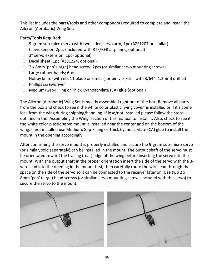
The Aileron (Aerobatic) Wing Set is mostly assembled right out of the box. Remove all parts from the box and check to see if the white color plastic ‘wing cover’ is installed or if it’s come lose from the wing during shipping/handling. If lose/not installed please follow the steps outlined in the ‘Assembling the Wing’ section of this manual to install it. Also, check to see if the white color plastic servo mount is installed near the center and on the bottom of the wing. If not installed use Medium/Gap‐Filling or Thick Cyanoacrylate (CA) glue to install the mount in the opening accordingly.
After confirming the servo mount is properly installed and secure the 9‐gram sub‐micro servo (or similar, sold separately) can be installed in the mount. The output shaft of the servo must be orientated toward the trailing (rear) edge of the wing before inserting the servo into the mount. With the output shaft in the proper orientation insert the side of the servo with the 3‐wire lead into the opening in the mount first, then carefully route the wire lead through the space on the side of the servo so it can be connected to the receiver later on. Use two 2 x 8mm ‘pan’ (large) head screws (or similar servo mounting screws included with the servo) to secure the servo to the mount.

47
Next, select a two‐sided servo arm that has holes at least 7/16”–1/2” (11–13mm) from the center on either side. USE EXTMREME CARE AND A HOBBY KNIFE WITH A SHARP NO.11 BLADE, OR A PIN VISE/DRILL WITH A 3/64” (1.2mm) DRILL BIT, TO VERY CAREFULLY ENLARGE THE HOLES IN THE POSITIONS YOU PLAN TO USE JUST ENOUGH SO THE ‘Z‐BENDS’ OF THE PUSHRODS CAN PASS THROUGH THEM. It’s very important that you DO NOT enlarge the holes more than necessary otherwise the pushrods will be too loose in the holes potentially resulting in ‘slop/play’ that may make it difficult to properly trim and control the ailerons in flight. Of course it’s also important that the pushrods are not installed too tightly in the holes (the pushrods should rotate freely but without slop/play).
After selecting and preparing a suitable servo arm, unplug the rudder servo 3‐wire lead from the ‘AILE’ (aileron) channel of the receiver then plug the lead/connector from the servo you installed in the wing into the AILE (aileron) channel instead. NOTE: You can install the optional ‘servo extension’ between the receiver and aileron servo lead to make it easier to connect/disconnect the servo now and when removing/installing the wing in the future. Turn the transmitter on, center the aileron trim lever (located immediately below the right‐hand stick) and connect the LiPo battery to the ESC to power on the receiver and servos. Check to be sure the ‘aileron’ servo responds to left and right control inputs correctly then center the right‐hand stick. IMPORTANT NOTE: If using the 6HPA transmitter included with the RTF version Gamma 370 and an Ares 9‐Gram Sub‐Micro Servo (AZS1207) for aileron control, be sure to move the ‘AILE’ (aileron) channel ‘SERVO REVERSE’ switch (located on the bottom front of the transmitter) to the ’NOR’ (normal) position before proceeding. This will ensure the aileron channel/servo is operating in the correct direction and centered properly before installing the servo arm. Also, for other brand transmitters and/or servos you’ll need to set the servo reversing as necessary to ensure the ailerons/aileron servo are responding correctly to control stick movements (as shown later in this section).

48
With the right‐hand stick and aileron trim lever centered the servo should also be centered. Now install the selected servo arm on the output shaft of the servo so it’s as close to perpendicular to the servo case as possible. It’s OK if the arm cannot be positioned exactly perpendicular to the case as long as it’s close. However, if the arm is more than 5–10 degrees away from perpendicular we suggest rotating the arm approximately 180‐degrees and/or checking other suitable servo arms until you find the one that fits with the best alignment overall.
After installing the servo arm on the output shaft in the position with the best possible alignment use one of the suitable screws included with the servo to secure the servo arm to the output shaft (do not over‐tighten!). With the servo arm installed and the right‐hand stick and aileron trim lever still centered carefully spread open each ‘clevis’ (the white plastic part installed on the threaded end of the metal pushrod) so you can insert the pin in the hole on each control horn/bracket attached to the ‘aileron torque rods’ installed in the wing. It may be helpful to insert a flat blade screwdriver (not included) into the clevis then carefully ‘twist’ it until it disengages the pin from the hole in the clevis. Also, it is not necessary to ‘snap’ the clevis back together until the centering adjustments are complete.

49
After connecting the clevises to the control horns/brackets view the trailing (rear) edge of the ailerons and wing from directly behind. The trailing edges of the ailerons should be ‘in line’ with the trailing edges of the wing when ailerons are properly ‘centered’. However, if the ailerons are ‘off center’ you can adjust the length/position of the pushrods/clevises as needed.
If either aileron is ‘above’ center carefully remove the clevis from the control horn/bracket and screw it ‘in’ (clockwise) one half to one full turn then insert the pin back into the control horn/bracket. Or, if either aileron is ‘below’ center screw the clevis ‘out’ (counter‐clockwise) one half to one full turn then insert the pin back into the control horn/bracket. View the trailing edges of the ailerons and wing from directly behind again and continue adjusting the length/position of the pushrod/clevis until both ailerons are centered appropriately.
NOTE: In some cases it may not be possible to exactly center the inboard and outboard portions of an aileron relative to the trailing edge of the wing. If you find this to be the case simply adjust the length/position of the pushrod/clevis to ‘split the difference’ between the inboard and outboard portions relative to the trailing edge of the wing.
NOTE: You should always rotate the clevis until the pin is perpendicular with the control horn to ensure the pin is not under any excessive load/pressure when inserted in the hole and during operation. In some cases it may not be possible to ‘exactly’ center the surface mechanically while properly aligning the pin. In these cases be sure the pin is properly aligned then adjust the position of the trim lever slightly as needed. Also, it will likely be necessary to make further adjustments to the position of the trim lever during flight as most surfaces do not end up in exactly the centered position when an airplane is trimmed properly for actual flight (but ‘centered’ is still the best starting point).
Also, we strongly recommend installing the included ‘clevis keepers’ to provide added security for the clevises. Typically you can carefully slide the keepers over the clevises when they are not connected to the control horn. Then, after connecting the clevis to the control horn and ‘snapping’ the clevis together you can slide the keepers into a position that does not allow them to ‘bind’ against the control horn/bracket during movement of the surface.

50
Attaching the Aileron (Aerobatic) Wing Before attaching the aileron (aerobatic) wing to the fuselage, plug the 3‐wire lead from the rudder servo (which was recently unplugged from the ‘AILE’ channel of the receiver), into the ‘RUDD’ (rudder) channel of the receiver. Confirm that the rudder is functioning correctly and moving in the right directions based on moving the left‐hand stick to the left (rudder should move to the left) and right (rudder should move to the right). IMPORTANT NOTE: If using the 6HPA transmitter included with the RTF version Gamma 370 be sure to move the ‘RUDD’ (rudder) channel ‘SERVO REVERSE’ switch (located on the bottom front of the transmitter) to the ’REV’ (reversed) position before proceeding. This will ensure the rudder channel/servo is operating in the correct direction. Use six (6) rubber bands to attach the aileron (aerobatic) wing to the fuselage. You can see more information regarding attaching the wing in the ‘Attaching the Wing’ section of this manual noting that you must now plug the 3‐wire lead for the aileron servo into the ‘AILE’ (aileron) channel of the receiver BEFORE attaching the wing. You must also keep the 3‐wire lead from coming into contact with/getting in the way of any moving parts or components inside the fuselage. With the wing attached to the fuselage orient the airframe so you can view the ailerons from behind. This will allow you to confirm that the ailerons are functioning correctly and moving in the right directions based on right‐hand/aileron control stick movements: Moving the right‐hand stick to the left will move the left aileron up and the right aileron down. This will roll/turn the airplane to the left.

51
Moving the stick to the right will move the right aileron up and the left aileron down. This will roll/turn the airplane to the right.
The aileron trim lever (located immediately below the right‐hand stick) can be used to help keep the airplane from rolling/turning left or right during flight with no right‐hand stick/aileron input. For example, if the airplane rolls/turns to the right in flight, add left aileron trim (by sliding the aileron trim lever to the left) until the airplane flies as straight as possible. After confirming the ailerons are functioning correctly and moving in the right directions based on right‐hand/aileron control stick movements you are ready to fly with the aileron (aerobatic) wing. Also, due to the differences in dihedral and airfoil, as well as the addition of ailerons, the airplane will indeed fly different with the aileron wing versus the standard wing installed. As a result you should treat the first flight with the aileron wing the same as the first flight of a new model.
The major airframe components (wing, fuselage and tails) of the Gamma 370 are molded from lightweight and durable EPO foam. Most damage can be repaired using transparent ‘packing’ tape and/or Cyanoacrylate (CA) glue. We recommend Medium/Gap‐Filling CA for most repairs, though Thin or even Thick viscosity can also be used for some others.
And in the unfortunate event that any part cannot be repaired, a full‐line of replacement parts is available separately. Please visit our web site at www.Ares‐RC.com, contact your local HobbyTown USA® store or visit www.HobbyTown.com for more information and to purchase replacement parts.
Repairs

52
Item Number Description AZSB10002S20T 1000mAh 2‐Cell/2S 7.4V 20C LiPo Battery, Tamiya Connector AZSC205C 205C 2‐Cell/2S 7.4V LiPo, 0.5A DC Balancing Charger AZSC1205PS 1205PS 100‐120V AC to 12V DC Adapter, 0.5‐Amp Power SupplyAZS1200 Gamma 370 RTF AZS1202 Gamma 370 RFR (Ready‐For‐Receiver)AZS1206 6‐Channel Park Flyer Receiver: Gamma 370AZS1207 9‐Gram Sub‐Micro Servo: Gamma 370AZS1207GS 9‐Gram Sub‐Micro Servo Gear Set: Gamma 370AZS1208AMD2 6HPA 6‐Channel HP Airplane Transmitter, Mode 2: Gamma 370 AZS1209 370 Motor w/Pinion Gear: Gamma 370AZS1210 20‐Amp Brushed Motor ESC: Gamma 370AZS1211 370 Gearbox w/Shaft: Gamma 370AZS1212 370 Gearbox Propeller Shaft w/Gear: Gamma 370AZS1213 Standard Wing Set: Gamma 370AZS1214 Tail Set: Gamma 370AZS1215 Fuselage Set: Gamma 370AZS1216 Main Landing Gear Set: Gamma 370AZS1217 Landing Gear Mount/Battery Hatch Set: Gamma 370 AZS1218 Tail Wheel Set: Gamma 370AZS1219 Pushrod Set: Gamma 370AZS1220 Control Horn Set: Gamma 370AZS1221 Cowl: Gamma 370AZS1222 Prop Saver: Gamma 370AZS1223 Spinner: Gamma 370AZS1224 Decal Sheet: Gamma 370AZS1225 Rubber Bands (8): Gamma 370AZS1226 Aileron (Aerobatic) Wing Set: Gamma 370AZS1227 370 Brushless Power System Upgrade Combo (Mount, Motor and ESC)AZS1228 370 Brushless Outrunner Motor Stick Mount: Gamma 370 AZS1229 370 Brushless Outrunner Motor, 1250Kv: Gamma 370 AZS1230 18‐Amp Brushless Motor ESC: Gamma 370AZSP0860SF 8 x 6 Slow Flyer Propeller: Gamma 370AZSP0970SF 9 x 7 Slow Flyer Propeller: Gamma 370
Replacement Parts List

53
30-Day Limited Warranty Term Period:We warranty that the Product(s) purchased (the “Product”) will be free from defects in materials and work¬manship when the product is new (before being used) for the limited warranty term period, 30 days, from the date of purchase by the Purchaser.If you believe a defect in material, workmanship, etc. was not apparent when the Product was new and only became evident after the Product was used, take the following steps. If you purchased the Product at a HobbyTown store, please contact your local HobbyTown store for warranty support and/or service. If you purchased the Product from the Firelands website, use the contact information found under the Support heading to contact Firelands directly.If you contact Firelands, you may be asked to send the product to Firelands, at your cost, for inspection. Provided the warranty conditions have been met within the warranty term period, the components that are found to be defective, incorrectly manufactured or assembled may be repaired or replaced, at the sole discretion of Firelands. Your warranty item will be returned to you at Firelands’ expense. In the event your product needs repair or a replacement part that is not covered by this warranty, your local HobbyTown store or Firelands can assist you with support and in obtaining the genuine replacement parts to repair your Prod¬uct. Firelands will charge $40.00 per hour plus the cost of replacement parts to service your vehicle if after contacting you, you so authorize such repairs. Your product will be returned to you at your expense.If you purchased your Product from a HobbyTown Internet site not affiliated with a local store, please consult that site for its support and service policies. You can also find more information at www.Hobbytown.com., by emailing [email protected] or call 800-205-6773
For more information regarding the Academy of Model Aeronautics (AMA) including the benefits of membership, insurance coverage and more, please visit www.ModelAircraft.org.
A. GENERAL: A model aircraft is a non‐human‐carrying aircraft capable of sustained flight in
the atmosphere. It may not exceed limitations of this code and is intended exclusively for sport, recreation and/or competition. All model flights must be conducted in accordance with this safety code and any additional rules specific to the flying site.
1. Model aircraft will not be flown:(a) In a careless or reckless manner.(b) At a location where model aircraft activities are prohibited.
Warranty, Support and Service
AMA National Model Aircraft Safety Code

54
2. Model aircraft pilots will: (a) Yield the right of way to all man carrying aircraft. (b) See and avoid all aircraft and a spotter must be used when appropriate. (AMA Document #540‐D‐See and Avoid Guidance.) (c) Not fly higher than approximately 400 feet above ground level within three (3) miles of an airport, without notifying the airport operator. (d) Not interfere with operations and traffic patterns at any airport, heliport or seaplane base except where there is a mixed use agreement. (e) Not exceed a takeoff weight, including fuel, of 55 pounds unless in compliance with the AMA Large Model Aircraft program. (AMA Document 520‐A) (f) Ensure the aircraft is identified with the name and address or AMA number of the owner on the inside or affixed to the outside of the model aircraft. (This does not apply to model aircraft flown indoors). (g) Not operate aircraft with metal‐blade propellers or with gaseous boosts except for helicopters operated under the provisions of AMA Document #555. (h) Not operate model aircraft while under the influence of alcohol or while using any drug which could adversely affect the pilot’s ability to safely control the model. (i) Not operate model aircraft carrying pyrotechnic devices which explode or burn, or any device which propels a projectile or drops any object that creates a hazard to persons or property.
Exceptions:
Free Flight fuses or devices that burn producing smoke and are securely attached to the model aircraft during flight.
Rocket motors (using solid propellant) up to a G‐series size may be used provided they remain attached to the model during flight. Model rockets may be flown in accordance with the National Model Rocketry Safety Code but may not be launched from model aircraft.
Officially designated AMA Air Show Teams (AST) are authorized to use devices and practices as defined within the Team AMA Program Document (AMA Document #718).
(j) Not operate a turbine‐powered aircraft, unless in compliance with the AMA turbine regulations. (AMA Document #510‐A).
3. Model aircraft will not be flown in AMA sanctioned events, air shows or model demonstrations unless: (a) The aircraft, control system and pilot skills have successfully demonstrated all maneuvers intended or anticipated prior to the specific event. (b) An inexperienced pilot is assisted by an experienced pilot.
4. When and where required by rule, helmets must be properly worn and fastened. They must be OSHA, DOT, ANSI, SNELL or NOCSAE approved or comply with comparable standards.
55
B. RADIO CONTROL (RC) 1. All pilots shall avoid flying directly over unprotected people, vessels, vehicles or
structures and shall avoid endangerment of life and property of others. 2. A successful radio equipment ground‐range check in accordance with manufacturer’s
recommendations will be completed before the first flight of a new or repaired model aircraft.
3. At all flying sites a safety line(s) must be established in front of which all flying takes place (AMA Document #706‐Recommended Field Layout): (a) Only personnel associated with flying the model aircraft are allowed at or in front of the safety line. (b) At air shows or demonstrations, a straight safety line must be established. (c) An area away from the safety line must be maintained for spectators. (d) Intentional flying behind the safety line is prohibited.
4. RC model aircraft must use the radio‐control frequencies currently allowed by the Federal Communications Commission (FCC). Only individuals properly licensed by the FCC are authorized to operate equipment on Amateur Band frequencies.
5. RC model aircraft will not operate within three (3) miles of any pre‐existing flying site without a frequency‐management agreement (AMA Documents #922‐ Testing for RF Interference; #923‐ Frequency Management Agreement)
6. With the exception of events flown under official AMA Competition Regulations, excluding takeoff and landing, no powered model may be flown outdoors closer than 25 feet to any individual, except for the pilot and the pilot's helper(s) located at the flight line.
7. Under no circumstances may a pilot or other person touch a model aircraft in flight while it is still under power, except to divert it from striking an individual. This does not apply to model aircraft flown indoors.
8. RC night flying requires a lighting system providing the pilot with a clear view of the model’s attitude and orientation at all times.
9. The pilot of a RC model aircraft shall: (a) Maintain control during the entire flight, maintaining visual contact without enhancement other than by corrective lenses prescribed for the pilot. (b) Fly using the assistance of a camera or First‐Person View (FPV) only in accordance with the procedures outlined in AMA Document #550.

56
www.Ares-RC.com
© 2012
Rev 04.22.12