ares ultra-micro trainer 100 rtf instruction manual 092011 · work or the use of glue and tape....
TRANSCRIPT
1
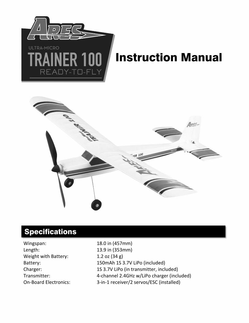
Wingspan: 18.0 in (457mm) Length: 13.9 in (353mm) Weight with Battery: 1.2 oz (34 g) Battery: 150mAh 1S 3.7V LiPo (included) Charger: 1S 3.7V LiPo (in transmitter, included) Transmitter: 4‐channel 2.4GHz w/LiPo charger (included) On‐Board Electronics: 3‐in‐1 receiver/2 servos/ESC (installed)
Specifications
Instruction Manual
2
Specifications ............................................................................................................................. 1
Introduction ............................................................................................................................... 3
Safety Precautions and Warnings .............................................................................................. 3
FCC Information ......................................................................................................................... 4
Ultra‐Micro Trainer 100 RTF Contents ....................................................................................... 5
Before the First Flight Checklist ................................................................................................. 6
Flight Checklist ........................................................................................................................... 6
Installing the Landing Gear ........................................................................................................ 7
Installing the Transmitter Batteries ........................................................................................... 7
Transmitter Details .................................................................................................................... 8
LiPo Battery Warnings and Usage Guidelines .......................................................................... 10
Charging the LiPo Flight Battery ............................................................................................... 12
Installing the LiPo Flight Battery .............................................................................................. 13
Control Unit Initialization and Arming ..................................................................................... 14
Flight Controls and Trimming ................................................................................................... 17
Selecting a Flying Area ............................................................................................................. 20
Flying ........................................................................................................................................ 20
Transmitter and Receiver Binding/Linking ............................................................................... 23
Removing/Installing the Wing .................................................................................................. 24
Repairs ..................................................................................................................................... 25
Replacement Parts List ............................................................................................................. 25
Warranty, Support and Service ................................................................................................ 26
Notes ........................................................................................................................................ 27
Table of Contents
3
The Ares™ [air‐eez] Ultra‐Micro Trainer 100 is perfect for first‐time pilots looking for an airplane with the size and stability that helps them learn to fly in less space and in less time than ever before. While you learn the basics of flying, the classic high‐wing trainer design will deliver confidence‐inspiring stability and easy control. The ultra‐micro size also allows you to fly in smaller outdoor spaces like a yard or park, or even indoors in a large gym. Plus, the durable and lightweight construction means you don’t always have to worry about damage after less than perfect landings. Another great feature of the Ultra‐Micro Trainer 100 includes a full‐airfoil wing design that allows for smooth and stable flying outdoors in light winds that would often ground other similar class models. The wing is also removable using an exclusive magnetic attachment design for more compact transport and is extremely easy to replace without time consuming work or the use of glue and tape. Best of all, the airframe is 100% factory‐assembled and ready‐to‐fly right out of the box – no tools required! The Ultra‐Micro Trainer 100 also includes AA batteries for the 4‐channel transmitter equipped with interference‐free 2.4GHz technology, digital trims and a built‐in LiPo battery charger. And the included 150mAh 1S 3.7V LiPo battery delivers long flight times of up to 20+ minutes per charge. That means there’s nothing extra to buy and you can be ready to fly within minutes of opening the box.
And although the Ultra‐Micro Trainer 100 is ready‐to‐fly right out the box, please take the time to read through this manual for more information about battery safety and charging, control checks and more before making your first flight. Please also visit our web site at www.Ares‐RC.com for additional information including product updates, bulletins, videos and more. Failure to use this product in the intended manner as described in the following instructions can result in damage and/or personal injury. An RC airplane is not a toy! If misused it can cause serious bodily harm and damage to property. Keep items that could become entangled in the propeller blades away from the propeller, including loose clothing, tools, etc. Be especially sure to keep your hands, face and other parts of your body away from the propeller blades.
Introduction
Safety Precautions and Warnings
4
As the user of this product you are solely and wholly responsible for operating it in a manner that does not endanger yourself and others or result in damage to the product or the property of others. This model is controlled by a radio signal that is subject to possible interference from a variety of sources outside your control. This interference can cause momentary loss of control so it is advisable to always keep a safe distance from objects and people in all directions around your model as this will help to avoid collisions and/or injury.
• Never operate your model if the voltage of the batteries in the transmitter is too low. • Always operate your model in an open area away from obstacles, people, vehicles,
buildings, etc. • Carefully follow the directions and warnings for this and any optional support
equipment (chargers, rechargeable batteries, etc.). • Keep all chemicals, small parts and all electronic components out of the reach of
children. • Moisture causes damage to electronic components. Avoid water exposure to all
electronic components, parts, etc. not specifically designed and protected for use in water.
• Never lick or place any portion of your model in your mouth as it could cause serious injury or even death.
This device complies with part 15 of the FCC rules. Operation is subject to the following two conditions: (1) This device may not cause harmful interference, and (2) this device must accept any interference received, including interference that may cause undesired operation. Caution: Changes or modifications not expressly approved by the party responsible for compliance could void the user’s authority to operate the equipment. This product contains a radio transmitter with wireless technology which has been tested and found to be compliant with the applicable regulations governing a radio transmitter in the 2.400GHz to 2.4835GHz frequency range. The associated regulatory agencies of the following countries recognize the noted certifications for this product as authorized for sale and use: USA
FCC Information
5
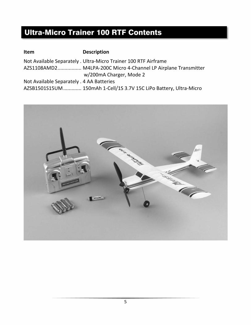
Item Description
Not Available Separately . Ultra‐Micro Trainer 100 RTF Airframe AZS1108AMD2 ................. M4LPA‐200C Micro 4‐Channel LP Airplane Transmitter w/200mA Charger, Mode 2 Not Available Separately . 4 AA Batteries AZSB1501S15UM ............. 150mAh 1‐Cell/1S 3.7V 15C LiPo Battery, Ultra‐Micro
Ultra-Micro Trainer 100 RTF Contents

6
PLEASE NOTE: This checklist is NOT intended to replace the content included in this instruction manual. Although it can be used as a quick start guide, we strongly suggest reading through this manual completely before proceeding.
Remove and inspect all contents
Install the four AA batteries in the transmitter
Begin charging the flight battery (connect it to the charger in the transmitter)
Install the flight battery in the airplane (after it’s been fully charged)
Test the controls to confirm proper operation
Familiarize yourself with the controls
Find a suitable area for flying
PLEASE NOTE: This checklist is NOT intended to replace the content included in this instruction manual. Although it can be used as a quick start guide, we strongly suggest reading through this manual completely before proceeding.
Always turn the transmitter on first
Plug the flight battery into the model
Allow the control unit to initialize and arm properly
Fly the model (hand‐launch or takeoff from a flat/level surface)
Land the model (land on a flat/level surface)
Unplug the flight battery from the model
Always turn the transmitter off last
Before the First Flight Checklist
Flight Checklist

7
The main landing gear is installed in the slot/opening located on the bottom of the fuselage and just behind the battery compartment. Use moderate pressure to ‘squeeze’ the landing gear legs together then slide the landing gear into the slot as shown (you can also remove the landing gear by doing the same). Also, be sure the landing gear is installed so it angles forward slightly when viewing the airplane directly from the side.
Install the four included AA batteries in the back of the transmitter by first removing the battery compartment cover/door. Ensure proper polarity of the batteries before installing them as noted by the markings molded into the battery compartment, then re‐install the compartment cover/door. Check for proper operation of the transmitter by switching the power switch on (slide it to the right). You should hear three beeps/tones from the transmitter while the LED indicator directly above the power switch begins to glow solid red. This indicates the transmitter is powered on and the AA batteries are installed correctly.
Installing the Transmitter Batteries
Installing the Landing Gear
8
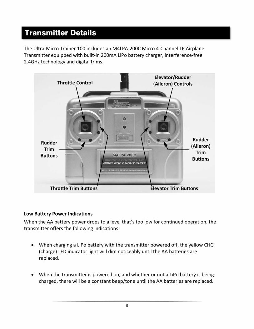
The Ultra‐Micro Trainer 100 includes an M4LPA‐200C Micro 4‐Channel LP Airplane Transmitter equipped with built‐in 200mA LiPo battery charger, interference‐free 2.4GHz technology and digital trims.
Low Battery Power Indications
When the AA battery power drops to a level that’s too low for continued operation, the transmitter offers the following indications:
When charging a LiPo battery with the transmitter powered off, the yellow CHG (charge) LED indicator light will dim noticeably until the AA batteries are replaced.
When the transmitter is powered on, and whether or not a LiPo battery is being charged, there will be a constant beep/tone until the AA batteries are replaced.
Transmitter Details

9
Antenna Position/Orientation
The RF output signals transmit best/strongest from the shaft of the antenna rather than from the tip. As a result you should never point the tip of the antenna directly at the model. Also, the transmitter antenna can be rotated and folded up to 90° so be sure to hold the transmitter and position the antenna as needed to ensure the best possible signal transmission.
Control/Servo Reversing
The M4LPA‐200C transmitter features control/servo reversing functionality for the rudder, elevator and aileron channels. The control/servo directions were set correctly at the factory for the Ultra‐Micro Trainer 100, however, in case you use the electronics in other models later on please follow these steps to change the control/servo directions as needed (complete all steps with the transmitter powered on):
Rudder Channel Control/Servo Reversing
Press and hold the right rudder trim button, then press the left rudder trim button. Release both buttons and the control/servo direction will be reversed.
Elevator Channel Control/Servo Reversing
Press and hold the right rudder trim button, then press the down elevator trim button. Release both buttons and the control/servo direction will be reversed.
Aileron Channel Control/Servo Reversing
Press and hold the right rudder trim button, then press the right aileron trim button. Release both buttons and the control/servo direction will be reversed.
NOTE: The aileron channel is used to control the rudder on the Ultra‐Micro Trainer 100 in order to ensure easier transition into 4‐channel models later on.
10
IMPORTANT NOTE: Lithium Polymer batteries are significantly more volatile than the alkaline, NiCd or NiMH batteries also used in RC applications. All instructions and warnings must be followed exactly to prevent property damage and/or personal injury as mishandling of LiPo batteries can result in fire. By handling, charging or using the included LiPo battery you assume all risks associated with LiPo batteries. If you do not agree with these conditions, please return your complete product in new, unused condition to the place of purchase immediately. And although the 150mAh 1‐Cell/1S 3.7V 15C LiPo Battery (AZSB1501S15UM) included with your Ares™ Ultra‐Micro Trainer 100 is intended to be charged safely using the LiPo battery charger built into the included M4LPA‐200C Micro 4‐Channel LP Airplane Transmitter w/200mA Charger (AZS1108AMD2), you must read the following safety instructions and warnings before handling, charging or using the LiPo battery.
• You must charge the LiPo battery in a safe area away from flammable materials.
• Never charge the LiPo battery unattended at any time. When charging the battery you should always remain in constant observation to monitor the charging process and react immediately to any potential problems that may occur.
• After flying/discharging the battery you must allow it to cool to ambient/room temperature before recharging.
• To charge the battery you must use only the LiPo battery charger built into the included M4LPA‐200C Micro 4‐Channel LP Airplane Transmitter w/200mA Charger (AZS1108AMD2) or a suitably compatible LiPo battery charger. Failure to do so may result in a fire causing property damage and/or personal injury. DO NOT use a NiCd or NiMH charger.
• If at any time during the charge or discharge process the battery begins to balloon or swell, discontinue charging or discharging immediately. Quickly and safely disconnect the battery, then place it in a safe, open area away from flammable materials to observe it for at least 15 minutes. Continuing to charge or discharge a battery that has begun to balloon or swell can result in a fire. A battery that has ballooned or swollen even a small amount must be removed from service completely.
• Store the battery at room temperature, approximately 68–77° Fahrenheit (F), and in a dry area for best results.
LiPo Battery Warnings and Usage Guidelines

11
• When transporting or temporarily storing the battery, the temperature range should be from approximately 40–100°F. Do not store the battery or model in a hot garage, car or direct sunlight whenever possible. If stored in a hot garage or car the battery can be damaged or even catch fire.
• Do not over‐discharge the LiPo flight battery. Discharging the LiPo flight battery too low can cause damage to the battery resulting in reduced power, flight duration or failure of the battery entirely.
LiPo cells should not be discharged to below 3.0V each under load. In the case of the 1‐Cell/1S 3.7V LiPo battery used to power the Ultra‐Micro Trainer 100 you will not want to allow the battery to fall below 3.0V during flight.
The 3‐in‐1 control unit features a soft low voltage cutoff (LVC) that smoothly reduces power to the motor/power system (regardless of the power level you have set with the left‐hand/throttle stick) to let you know the voltage of the battery is close to the 3.0V minimum. However, even before this reduction in power, if you find that more than the typical amount of throttle/power is required to cruise or climb you should land the model and disconnect the battery immediately to prevent over‐discharge.
And while it is possible to power the model up and fly again after the soft LVC occurs, this is NOT recommended. Continued discharging can result in reaching the hard LVC which may cause permanent damage to the LiPo battery resulting in lost power and flight duration during subsequent fights (or failure of the battery entirely).
Also, it is not recommended that you fly to the soft LVC every time you fly. Instead you should be aware of the power level of the battery/airplane throughout the flight, and if at any time the airplane begins to require more throttle/power than typical to maintain cruise or climb, you should land the airplane and disconnect the LiPo battery immediately. Constantly discharging the battery to the soft LVC can still cause permanent damage to the battery so it’s best to use a timer or stop‐watch to time the duration of your flights and to stop flying at a reasonable time before the soft LVC is reached.

12
You must charge the included 150mAh 1‐Cell/1S 3.7V 15C LiPo Battery (AZSB1501S15UM) using the LiPo battery charger built into the included M4LPA‐200C Micro 4‐Channel LP Airplane Transmitter w/200mA Charger (AZS1108AMD2) or a suitably compatible LiPo battery charger. Charging the LiPo battery using a non‐LiPo battery compatible charger (such as a NiCd or NiMH battery charger), or even a different LiPo battery charger with the incorrect settings, may result in damage to the battery or even fire resulting in property damage and/or personal injury.
Please follow these steps to charge the LiPo battery with the transmitter’s built‐in charger:
Carefully open the small hatch located near the bottom left corner of the transmitter and extend the charge lead outside of the transmitter case. You can leave the hatch open or close it by routing the charge lead through the small cutout/opening in the hatch door.
Connect the battery to the connector at the end of the charge lead extending from the transmitter. YOU MUST BE CAREFUL TO ENSURE PROPER POLARITY BEFORE MAKING THE CONNECTION by aligning the small red circle marking on the housing of the battery with the small red circle marking on the charge lead connector. While the white connectors are ‘keyed’ to minimize the risk of a reverse polarity connection, if you force them it is possible to make connection with the incorrect polarity potentially causing damage to the battery and/or charger (transmitter). When the circle markings are properly aligned for correct polarity, connecting the white connectors should require only a minimal amount of pressure to achieve the light ‘click’ that indicates a secure connection.
Charging the LiPo Flight Battery

13
When the battery is connected to the charge lead securely and with the proper polarity the CHG (charge) LED indicator on the charger will glow solid yellow. The battery will be charging anytime the LED indicator is glowing solid yellow and whether or not the transmitter is powered on.
It will take approximately 40‐60 minutes to charge a fully discharged (not over‐discharged) battery. And when the battery is fully charged the LED indicator will stop glowing yellow entirely. When the LED indicator is no longer glowing you can remove the battery from the charger as it is now fully charged and ready for use.
NOTE: The LiPo battery included with your model will arrive partially charged. For this reason the initial charge may only take approximately 20‐30 minutes. NOTE: It’s safer and better for the longevity of the battery to store it only partially charged for any length of time. Storing the battery at approximately 50% charged (which is approximately 3.85V per cell) is typically best, however, it will take some careful management of the charge time and the use of a volt meter to achieve this voltage. If you have the equipment and skills to achieve the 50% charge level for storage it is recommended. If not, simply be sure to not store the battery fully charged whenever possible. In fact, as long as the battery will be stored at approximately room temperature and for no more than a few weeks before the next use, it may be best to store the battery in the discharged state after the last flight (as long as the battery was not over‐discharged on the last flight).
NOTE: You must ALWAYS turn the transmitter on first, BEFORE installing/connecting the LiPo flight battery. And before proceeding with the following steps, please be sure the transmitter is powered on. After the LiPo battery has been fully charged it’s ready to be installed in the airplane. However, the first step before installing the battery is to connect it to the 3‐in‐1 control unit. ALSO, YOU MUST BE CAREFUL TO ENSURE PROPER POLARITY BEFORE CONNECTING THE BATTERY TO THE 3‐IN‐1 CONTROL UNIT CONNECTOR. By orienting/aligning the small red circle marking on the housing of the battery with the small red circle marking on the connector for the 3‐in‐1 control unit you’ll be able to make the connection with the correct polarity.
Installing the LiPo Flight Battery

14
Also, although the white connectors are ‘keyed’ to minimize the risk of a reverse polarity connection, if you force them it is possible to make connection with the incorrect polarity potentially causing damage to the 3‐in‐1 control unit and/or battery. When the red circle markings are properly aligned for correct polarity, connecting the white connectors should require only a minimal amount of pressure to achieve the light ‘click’ that indicates secure connection.
After the LiPo battery is connected to the 3‐in‐1 control unit the unique magnetic attachment design makes it quick and easy to install the battery. Simply place the side of the battery with the magnetic attachments against the magnets located in the battery compartment and the battery will be mounted securely in the airplane.
To remove the LiPo flight battery, lift it away from the magnets then disconnect it from the 3‐in‐1 control unit. DO NOT power off the transmitter until the LiPo flight battery is removed from the airplane and the 3‐in‐1 control unit is powered off. REMEMBER: The transmitter is always on first and always off last!
Your Ultra‐Micro Trainer 100 is equipped with a compact and advanced 3‐in‐1 control unit. The control unit is a lightweight combination of 2.4GHz receiver, two servos and an electronic speed control (ESC).
This checklist includes the steps you must follow to ensure proper initialization, arming and operation of the control unit:
Control Unit Initialization and Arming
15
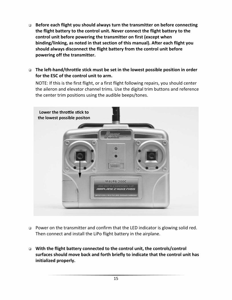
Before each flight you should always turn the transmitter on before connecting the flight battery to the control unit. Never connect the flight battery to the control unit before powering the transmitter on first (except when binding/linking, as noted in that section of this manual). After each flight you should always disconnect the flight battery from the control unit before powering off the transmitter.
The left‐hand/throttle stick must be set in the lowest possible position in order for the ESC of the control unit to arm.
NOTE: If this is the first flight, or a first flight following repairs, you should center the aileron and elevator channel trims. Use the digital trim buttons and reference the center trim positions using the audible beeps/tones.
Power on the transmitter and confirm that the LED indicator is glowing solid red. Then connect and install the LiPo flight battery in the airplane.
With the flight battery connected to the control unit, the controls/control surfaces should move back and forth briefly to indicate that the control unit has initialized properly.

16
As long as you had the left‐hand/throttle stick set to the lowest possible position during the initialization process the ESC/motor will now be armed. Use caution as the propeller will now spin with left‐hand/throttle stick input!
In case the controls/control surfaces do not move back and forth briefly:
• If the controls/control surfaces do not move back and forth briefly you do not have a positive radio frequency (RF) link between the transmitter and receiver of the control unit. First, check to be sure the transmitter is powered on and the LED indicator on the transmitter is glowing solid red. If the transmitter is powered on and functioning properly, disconnect the flight battery from the control unit. Then reconnect the flight battery and now the control unit should initialize and arm properly.
In case the controls/control surfaces move automatically but you have no control of the motor:
• If the controls/control surfaces move back and forth briefly but you do not have control of the motor, you have a positive RF link between the transmitter and receiver but the ESC/motor did not arm because the left‐hand/throttle stick may not be set to the correct position. Check to be sure the left‐hand/throttle stick is in the lowest possible position, and once in the correct position the ESC/motor will be armed.
After confirming the control unit is initialized and the ESC/motor has armed properly your Ultra‐Micro Trainer 100 is ready to fly. However, please review the following sections of the manual BEFORE proceeding with the first flight.

17
In the event you are not familiar with the controls of your Ultra‐Micro Trainer 100, please take the time to familiarize yourself with them as follows and before attempting your first flight. The left‐hand stick on the transmitter controls the throttle. When the left‐hand stick (also known as the ‘throttle’ stick) is in the lowest possible position the propeller will not spin.
Moving the stick upward will increase the speed/RPM of the propeller. Increasing the speed of the propeller increases the speed of the model and also provides the thrust needed to climb/increase altitude.
Decreasing the speed/RPM of the propeller by lowering the left‐hand stick will decrease the speed of the model and reduce thrust making it possible to descend/decrease altitude.
During flight you can also adjust the throttle to a position, typically between 1/3 and 2/3 power, to cruise at a given altitude and increase flight duration.
Flight Controls and Trimming
18
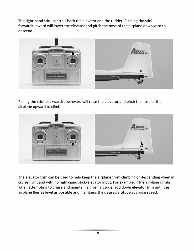
The right‐hand stick controls both the elevator and the rudder. Pushing the stick forward/upward will lower the elevator and pitch the nose of the airplane downward to descend.
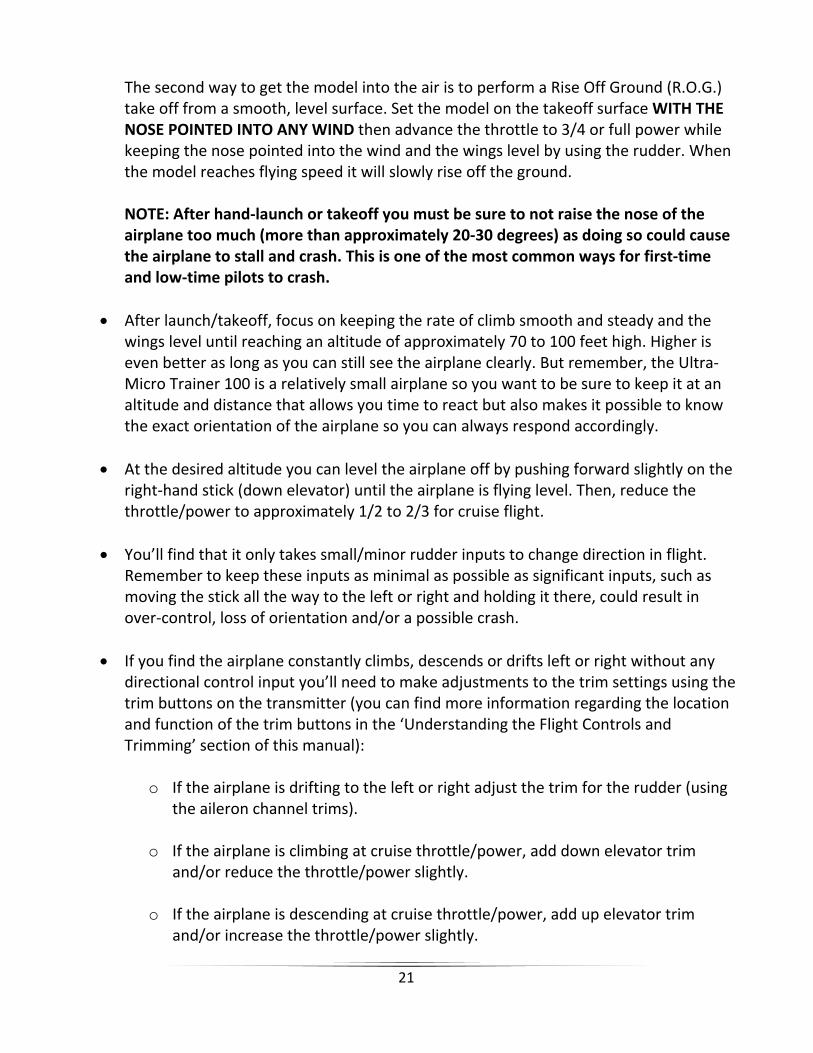
Pulling the stick backward/downward will raise the elevator and pitch the nose of the airplane upward to climb.
The elevator trim can be used to help keep the airplane from climbing or descending when in cruise flight and with no right‐hand stick/elevator input. For example, if the airplane climbs when attempting to cruise and maintain a given altitude, add down elevator trim until the airplane flies as level as possible and maintains the desired altitude at cruise speed.

19
Moving the stick to the left will move the rudder to the left. This will roll/turn the airplane to the left.
Moving the stick to the right will move the rudder to the right. This will roll/turn the airplane to the right.
The trim can be used to help keep the airplane from drifting/turning left or right during flight with no right‐hand stick/rudder input. For example, if the airplane drifts to the right in flight, add left trim until the airplane flies as straight as possible without drifting. And once you’re familiar with the primary controls of the airplane you’re almost ready to fly!

20
When you’re ready to make your first flights you’ll want to select an open outdoor area free of people and obstructions. We suggest an area approximately the size of a soccer field when making your first few flights. We also suggest flying over grass as it’s a much more forgiving surface that causes less damage in the unfortunate event of a crash. However, please note that when attempting to land on grass it can catch the landing gear, potentially causing the model to flip and become damaged. With this in mind, an ideal flying area allows for flying over grass and landing on a smoother surface such as asphalt or the dirt on a baseball field. Also, while the Ultra‐Micro Trainer 100’s full‐airfoil wing design helps make it possible to fly in light winds, we strongly suggest flying only in calm conditions until you’re familiar with the controls and handling of the model. Even light winds can make it much more difficult to learn to fly, and in some cases can even carry the model beyond your line of sight and the range of the transmitter signal. After you’ve properly trimmed the airplane in calm conditions and become familiar with its handling and capabilities, you’ll be able to fly in light winds and smaller outdoor areas. You’ll also be able to fly in larger indoor areas such as a basketball gym as your skills continue to improve. Now that you’ve selected a suitable flying area and the control unit is initialized and armed, your Ultra‐Micro Trainer 100 is ready to fly. And when making your first flights we suggest following these steps:
There are two ways to get the Ultra‐Micro Trainer 100 into the air. The first, and our suggested method for first‐time pilots, is to hand‐launch the model. This is easy to accomplish by holding the model in your hand with the wings level AND THE NOSE POINTED INTO ANY WIND. Then, advance the throttle to 3/4 or full power and gently ‘push’ the model forward with the nose level to or slightly above the horizon. The airplane will be flying almost immediately after it leaves your hand allowing you to focus on keeping the wings level while continuing to climb to a safe altitude.
Selecting a Flying Area
Flying
21
The second way to get the model into the air is to perform a Rise Off Ground (R.O.G.) take off from a smooth, level surface. Set the model on the takeoff surface WITH THE NOSE POINTED INTO ANY WIND then advance the throttle to 3/4 or full power while keeping the nose pointed into the wind and the wings level by using the rudder. When the model reaches flying speed it will slowly rise off the ground. NOTE: After hand‐launch or takeoff you must be sure to not raise the nose of the airplane too much (more than approximately 20‐30 degrees) as doing so could cause the airplane to stall and crash. This is one of the most common ways for first‐time and low‐time pilots to crash.
After launch/takeoff, focus on keeping the rate of climb smooth and steady and the wings level until reaching an altitude of approximately 70 to 100 feet high. Higher is even better as long as you can still see the airplane clearly. But remember, the Ultra‐Micro Trainer 100 is a relatively small airplane so you want to be sure to keep it at an altitude and distance that allows you time to react but also makes it possible to know the exact orientation of the airplane so you can always respond accordingly.
At the desired altitude you can level the airplane off by pushing forward slightly on the right‐hand stick (down elevator) until the airplane is flying level. Then, reduce the throttle/power to approximately 1/2 to 2/3 for cruise flight.
You’ll find that it only takes small/minor rudder inputs to change direction in flight. Remember to keep these inputs as minimal as possible as significant inputs, such as moving the stick all the way to the left or right and holding it there, could result in over‐control, loss of orientation and/or a possible crash.
If you find the airplane constantly climbs, descends or drifts left or right without any directional control input you’ll need to make adjustments to the trim settings using the trim buttons on the transmitter (you can find more information regarding the location and function of the trim buttons in the ‘Understanding the Flight Controls and Trimming’ section of this manual):
o If the airplane is drifting to the left or right adjust the trim for the rudder (using
the aileron channel trims).
o If the airplane is climbing at cruise throttle/power, add down elevator trim and/or reduce the throttle/power slightly.
o If the airplane is descending at cruise throttle/power, add up elevator trim
and/or increase the throttle/power slightly.

22
It’s important to continue making trim adjustments as needed until the airplane maintains straight and level flight with very little drifting or directional control input. Also, if this is your first airplane model it may be best to enlist the help of an experienced airplane pilot to trim the model for you before making your first flight. A properly trimmed airplane is much easier to fly!
When the airplane is properly trimmed practice making shallow (approximately 5‐15degree bank) turns by using a small amount of rudder to roll the airplane then a smallamount of elevator to keep the nose from dropping and to help ‘pull’ the airplanethrough the turn. Then apply the opposite direction rudder to bring the wing back tolevel before starting the next turn.
Sharper turns (approximately 15+ degree bank) will require more rudder and elevatorinput. Try not to excessively bank the model beyond 30‐45 degrees as doing so cancause the airplane to lose altitude very quickly.
If at any time during flight you feel like the airplane is drifting out of/beyond yourcontrol, simply release the elevator and rudder controls. In most cases this will allowthe airplane to return to nearly level flight on its own. Also, if the airplane is flyingtoo high or too far away, lower the throttle completely to power off the motor andallow the airplane to descend to a more reasonable altitude/position.
At typical cruise throttle/power settings the Ultra‐Micro Trainer 100 will fly for up to20+ minutes per charge. However, we strongly recommend using a timer to keep trackof your time in the air and to land after approximately 7‐10 minutes to ensure youhave plenty of power to practice landing approaches and to ‘go around’ if needed.
NOTE: You can lose all power abruptly if the voltage of the battery drops too low.
Reducing the throttle/power to less than 1/2 or 1/3 will allow the airplane to enter ashallow descent. This is helpful if the airplane has climbed too high and when it’s timeto set up for landing.
To land, point the nose directly into any wind at an altitude of approximately 50‐75feet above the ground and approximately 150‐300 feet away from the desired landingarea. Reduce the throttle/power to 1/3 as you descend slowly to approximately 20‐30feet, then lower the throttle/power to 1/4 or less. At approximately 2‐4 feet above theground lower the throttle/turn off the power completely while allowing the airplane todescend naturally. Just before the airplane contacts the ground add a small amount ofup elevator to bring the nose up and ‘flare’ for a smooth landing.
23
Later on you can practice landing with a small amount of throttle/power to help smooth out the approach and touchdown. However, you must be sure to lower the throttle/turn off the power completely if the prop comes into contact with the ground.
IN THE UNFORTUNATE EVENT OF A CRASH OR PROPELLER STRIKE, NO MATTER HOWMAJOR OR MINOR, YOU MUST LOWER THE LEFT‐HAND/THROTTLE STICK TO THELOWEST POSSIBLE POSITION AS QUICKLY AS POSSIBLE TO PREVENT DAMAGE TO THEESC OF THE CONTROL UNIT.
If you do not lower the left‐hand/throttle stick to the lowest possible position in the event of a crash/propeller strike it can result in damage to the ESC of the control unit which may require replacement of the control unit.
Note: Crash damage is not covered under warranty.
Once you’ve gained the experience and confidence in flying your airplane you canattempt more advanced maneuvers including:
Loops Stall Turns
Touch‐and‐Go’s Spot Landings
Binding/linking is the process of programming the receiver on the control unit to recognize the Globally Unique Identifier (GUID) code of a single specific transmitter. If you ever find it’s necessary to replace the transmitter or the receiver/control unit it will be necessary for you to bind/link the new transmitter or receiver/control unit accordingly for proper operation.
These steps outline the binding/linking process:
Switch the transmitter on and plug the flight battery to the control unit.
Simultaneously press the two throttle trim buttons (both the top and bottom buttonsto the right‐side of the left‐hand/throttle stick) and the transmitter will emit a series ofbeeps/tones indicating that it’s entered the binding/linking mode.
The binding/linking process is complete when the elevator and rudder controls/controlsurfaces move back and forth briefly and the transmitter stops emitting thebeeps/tones. You should now have full control of the airplane.
Transmitter and Receiver Binding/Linking
24
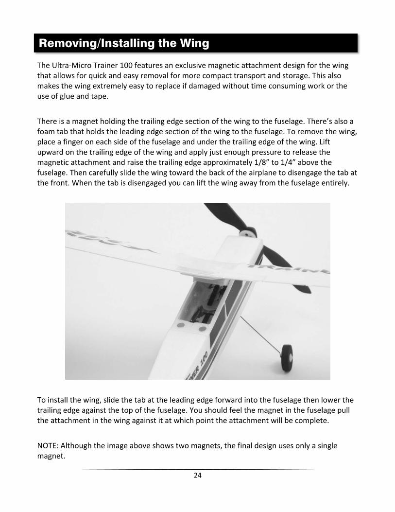
The Ultra‐Micro Trainer 100 features an exclusive magnetic attachment design for the wing that allows for quick and easy removal for more compact transport and storage. This also makes the wing extremely easy to replace if damaged without time consuming work or the use of glue and tape.
There is a magnet holding the trailing edge section of the wing to the fuselage. There’s also a foam tab that holds the leading edge section of the wing to the fuselage. To remove the wing, place a finger on each side of the fuselage and under the trailing edge of the wing. Lift upward on the trailing edge of the wing and apply just enough pressure to release the magnetic attachment and raise the trailing edge approximately 1/8” to 1/4” above the fuselage. Then carefully slide the wing toward the back of the airplane to disengage the tab at the front. When the tab is disengaged you can lift the wing away from the fuselage entirely.
To install the wing, slide the tab at the leading edge forward into the fuselage then lower the trailing edge against the top of the fuselage. You should feel the magnet in the fuselage pull the attachment in the wing against it at which point the attachment will be complete.
NOTE: Although the image above shows two magnets, the final design uses only a single magnet.
Removing/Installing the Wing

25
The major airframe components (wing, tails and fuselage) of the Ultra‐Micro Trainer 100 are molded from lightweight and durable EPS foam. Most damage can be repaired using Odorless, also known as ‘Foam‐Safe’, Cyanoacrylate (CA) glue. We recommend Medium/Gap‐Filling for most repairs, though Thin can also be used for some others. Also, if you use Accelerator, it must also be Foam‐Safe and compatible with your chosen CA glue.
And in the unfortunate event that any part cannot be repaired, a full‐line of replacement parts is available separately. Please visit our web site at www.Ares‐RC.com or contact your local HobbyTown USA® store for more information and to purchase replacement parts.
Item Number Description
AZSB1501S15UM 150mAh 1‐Cell/1S 3.7V 15C LiPo Battery, Ultra‐Micro
AZS1106 3‐Channel, 3‐in‐1 Control Unit; Rx/2 SXs/ESC: UMT
AZS1107 Replacement Rotary Servo Mechanics: UMT
AZS1108AMD2 M4LPA‐200C Micro 4‐Channel LP Airplane Transmitter w/200mA Charger, Mode 2: UMT
AZS1109 Motor w/Pinion Gear: UMT
AZS1110 Gearbox w/Motor: UMT
AZS1111 Gearbox w/Shaft: UMT
AZS1112 Propeller Shaft w/Gear: UMT
AZS1113 Wing w/Decals: UMT
AZS1114 Tail Set w/Decals and Hardware: UMT
AZS1115 Fuselage w/Decals: UMT
AZS1116 Main Landing Gear Set: UMT
AZS1117 Pushrod Set: UMT
AZS1118 Decal Sheet: UMT
AZSP0550275UM 5.5 x 2.75 (140 x 70mm) Ultra‐Micro Propeller w/Spinner: UMT
Replacement Parts List
Repairs

26
30-Day Limited Warranty Term Period:We warranty that the Product(s) purchased (the “Product”) will be free from defects in materials and work¬manship when the product is new (before being used) for the limited warranty term period, 30 days, from the date of purchase by the Purchaser.
If you believe a defect in material, workmanship, etc. was not apparent when the Product was new and only became evident after the Product was used, take the following steps. If you purchased the Product at a HobbyTown store, please contact your local HobbyTown store for warranty support and/or service. If you purchased the Product from the Firelands website, use the contact information found under the Support heading to contact Firelands directly.
If you contact Firelands, you may be asked to send the product to Firelands, at your cost, for inspection. Provided the warranty conditions have been met within the warranty term period, the components that are found to be defective, incorrectly manufactured or assembled may be repaired or replaced, at the sole discretion of Firelands. Your warranty item will be returned to you at Firelands’ expense. In the event your product needs repair or a replacement part that is not covered by this warranty, your local HobbyTown store or Firelands can assist you with support and in obtaining the genuine replacement parts to repair your Prod¬uct. Firelands will charge $40.00 per hour plus the cost of replacement parts to service your vehicle if after contacting you, you so authorize such repairs. Your product will be returned to you at your expense.
If you purchased your Product from a HobbyTown Internet site not affiliated with a local store, please consult that site for its support and service policies. You can also find more information at
www.Hobbytown.com., by emailing [email protected] or call 800-205-6773
Warranty, Support and Service

27
____________________________________________________________________________________________________________________________________________________________________________________________________________________________________________________________________________________________________________________________________________________________________________________________________________________________________________________________________________________________________________________________________________________________________________________________________________________________________________________________________________________________________________________________________________________________________________________________________________________________________________________________________________________________________________________________________________________________________________________________________________________________________________________________________________________________________________________________________________________________________________________________________________________________________________________________________________________________________________________________________________________________________________________________________________________________________________________________________________________________________________________________________________________________________________________________________________________________________________________________________________________________________________________________________________________________________________________________________________________________________________________________________________________________________________________________________________________________________________________________________________________________________________________________________________________________________________________________________________________________________________________________________________________________________________________________________________________________________________________________________________________________________________________________________________________________________________________________________________________________________________________________________________________________________________________________________________ ________________________________________________________________________________________________________________________________________________________________________________________________________________________________________________________________________________________________________________________________________________________________________________________________________________________________________________________________________
Notes

28
www.Ares-RC.com © 2011
Available Exclusively at HobbyTown USA®
www.HobbyTownUSA.com
Rev 09.20.11