institutionen för datavetenskap - retawprojects.comretawprojects.com/uploads/fulltext01_(2).pdf ·...
TRANSCRIPT
“report” — 2011/9/14 — 17:10 — page 1 — #1
Institutionen för datavetenskap Department of Computer and Information Science
Final Thesis
Lightweight M2M Solution on Android
Platform
by
Magnus Gustafsson
LIU-IDA/LITH-EX-A--11/031--SE
2011-09-14
Linköpings universitet
SE-581 83 Linköping, Sweden
Linköpings universitet
581 83 Linköping

“report” — 2011/9/14 — 17:10 — page 2 — #2
2
“report” — 2011/9/14 — 17:10 — page i — #3
Final thesis
Lightweight M2M Solution onAndroid Platform
by
Magnus Gustafsson
LIU-IDA/LITH-EX-A–11/031–SE
2011-09-14
Supervisor: Mikael Asplund (IDA)Daniel Pettersson (Attentec AB)
Examiner: Simin Nadjm-Tehrani

“report” — 2011/9/14 — 17:10 — page ii — #4

“report” — 2011/9/14 — 17:10 — page iii — #5
Abstract
Machine-to-machine communication (M2M) is a generic term for technolo-gies dealing with autonomous communication between machines. For thelast 10 years a wide range of business areas utilize a variety of differentM2M solutions for remote management of equipment. Common for almostall of those solutions is that they are expensive and require the infrastructureto be adapted to them. They are also usually built out of several differentsystems working together and thus there are several systems that requiremaintenance.
This thesis investigates the possibility to develop a lightweight alterna-tive to existing M2M solutions using only common devices and protocols.Lightweight here means that the system should be flexible, have a low costfor set-up and operation and that both ends should be mobile. By develop-ing a lightweight M2M architecture the technology may become available innew business areas and new types of services may arise.
In the thesis a prototype is implemented. The purpose of the prototypeis to practically verify whether a lightweight M2M solution is possible todevelop in this manner. The solution uses the Android platform for back-end and user interface and a Cinterion TC65T as slave device to which thesensors can be connected. The implemented system is limited in terms ofsecurity and performance but still acts as a proof of concept for this kind ofM2M solution.
iii

“report” — 2011/9/14 — 17:10 — page iv — #6
“report” — 2011/9/14 — 17:10 — page v — #7
Acknowledgements
This master thesis is performed at Attentec AB in Linkoping during March2011 to September 2011. It has been examined by Institutionen for Dataveten-skap (IDA), Linkopings Universitet.
I would like to thank my supervisor at Attentec AB, Daniel Pettersson,for his many ideas and Lars Lundberg for his commitment and aid in mywork. I would also like to thank my examiner, Simin Nadjm-Tehrani, andmy supervisor at IDA, Mikael Asplund, for their help with reviewing andimproving this report.

“report” — 2011/9/14 — 17:10 — page vi — #8

“report” — 2011/9/14 — 17:10 — page vii — #9
Glossary
ARM Advanced RISC Machine.ARM7 A generation of the ARM processor design.AT Commands Attention Commands. Command set often used
by modems and phones.
DIN rail Metal rail used to mount industrial equipment.
GPIO General Purpose Input/Output. May be Ana-log/Digital Converters, I2C, SPI, etc.
GPRS General Packet Radio Service. Set of standardsallowing data packets to be sent over GSM.GPRS is also known as 2.5G.
GSM Global System for Mobile Communications. Setof standards for the second generation mobilenetwork. GSM is also known as 2G.
GUI Graphical User Interface.
HTTP HyperText Transfer Protocol. Communicationprotocol used mainly to transfer web pages.
HTTPS HyperText Transfer Protocol Secure. A en-crypted version of HTTP.
I2C Inter-Integrated Circuit. A communication in-terface.
IEEE Institute of Electrical and Electronics Engi-neers.
IMEI International Mobile Equipment Identity.Unique number for each mobile device.
IMP-NG Information Module Profile - Next Generation.Profile for Java Micro Edition targeting deviceswithout display.
IP Internet Protocol.IPv4 Internet Protocol version 4. Uses 32-bit IP ad-
dresses (ex. 192.168.0.1).
vii

“report” — 2011/9/14 — 17:10 — page viii — #10
viii Glossary
IPv6 Internet Protocol version 6. Uses 128-bit IP ad-dresses (ex. 2001:db8:85a3:::8a2e:370:7334).
LAN Local Area Network.
M2M Machine-to-machine communication. Auto-nomic communication between machines. SeeSection 2.1 for details.
MAN Metropolitan Area NetworkMaster Server and user interface for the system. The
Android tablet in the implementation, see Sec-tion 3.4.
RISC Reduced Instruction Set Computer.RS232 Standard communications port. Also known as
COM-port.
SDK Software Development Kit.Slave Device physically connected to the monitored
sensors. The Cinterion TC65T device in the im-plementation, see Section 3.5.
SPI Serial Peripheral Interface. A communicationinterface.
SVN Subversion. Software for revision control andbackup.
TCP Transmission Control Protocol.
UI User Interface.Update session Event where the slave sends all sensor values
accumulated since the last update session to themaster (local concept only applicable for thisreport).
WLAN Wireless Local Area Network.
Zig-Bee Low power, low cost wireless network standard.
viii

“report” — 2011/9/14 — 17:10 — page ix — #11
Contents
1 Introduction 11.1 Background . . . . . . . . . . . . . . . . . . . . . . . . . . . . 11.2 Purpose and Objective . . . . . . . . . . . . . . . . . . . . . . 21.3 Limitations . . . . . . . . . . . . . . . . . . . . . . . . . . . . 31.4 Intended Audience . . . . . . . . . . . . . . . . . . . . . . . . 41.5 Thesis Overview . . . . . . . . . . . . . . . . . . . . . . . . . 4
2 Technologies 52.1 Machine-to-machine Communication . . . . . . . . . . . . . . 5
2.1.1 Definition . . . . . . . . . . . . . . . . . . . . . . . . . 52.1.2 Background . . . . . . . . . . . . . . . . . . . . . . . . 62.1.3 Current M2M Applications . . . . . . . . . . . . . . . 7
2.2 Communication Technologies . . . . . . . . . . . . . . . . . . 72.2.1 Network Standards . . . . . . . . . . . . . . . . . . . . 82.2.2 Communication Protocol . . . . . . . . . . . . . . . . 8
2.3 Cinterion TC65T . . . . . . . . . . . . . . . . . . . . . . . . . 82.3.1 Cinterion Wireless Modules GmbH . . . . . . . . . . . 92.3.2 Device Information . . . . . . . . . . . . . . . . . . . . 92.3.3 Internal Structure . . . . . . . . . . . . . . . . . . . . 9
2.4 Java Micro Edition . . . . . . . . . . . . . . . . . . . . . . . . 102.5 Android . . . . . . . . . . . . . . . . . . . . . . . . . . . . . . 11
2.5.1 History . . . . . . . . . . . . . . . . . . . . . . . . . . 112.5.2 Android for the Application Programmer . . . . . . . 12
3 Android-based M2M platform 153.1 Requirements . . . . . . . . . . . . . . . . . . . . . . . . . . . 15
3.1.1 Structure of Requirements . . . . . . . . . . . . . . . . 153.1.2 Functional Requirements . . . . . . . . . . . . . . . . 163.1.3 Non-functional Requirements . . . . . . . . . . . . . . 17
3.2 Major Design Choices . . . . . . . . . . . . . . . . . . . . . . 173.2.1 Android Platform . . . . . . . . . . . . . . . . . . . . 173.2.2 Terminal Module . . . . . . . . . . . . . . . . . . . . . 173.2.3 Communication Interface . . . . . . . . . . . . . . . . 18
3.3 System Overview . . . . . . . . . . . . . . . . . . . . . . . . . 19
ix
“report” — 2011/9/14 — 17:10 — page x — #12
x CONTENTS
3.3.1 Communication . . . . . . . . . . . . . . . . . . . . . . 193.4 Master Application . . . . . . . . . . . . . . . . . . . . . . . . 20
3.4.1 User Interface Activities . . . . . . . . . . . . . . . . . 223.4.2 Connection Service . . . . . . . . . . . . . . . . . . . . 253.4.3 SQLite Database . . . . . . . . . . . . . . . . . . . . . 253.4.4 Using the Master Application . . . . . . . . . . . . . . 26
3.5 Slave Application . . . . . . . . . . . . . . . . . . . . . . . . . 273.5.1 Structure of the Slave Application . . . . . . . . . . . 323.5.2 Using the Slave Application . . . . . . . . . . . . . . . 33
4 Evaluation 354.1 Requirement Verification . . . . . . . . . . . . . . . . . . . . . 354.2 System Viability . . . . . . . . . . . . . . . . . . . . . . . . . 384.3 Reliability . . . . . . . . . . . . . . . . . . . . . . . . . . . . . 394.4 Security . . . . . . . . . . . . . . . . . . . . . . . . . . . . . . 394.5 Performance . . . . . . . . . . . . . . . . . . . . . . . . . . . . 39
4.5.1 Performance Tests . . . . . . . . . . . . . . . . . . . . 404.6 Time-outs . . . . . . . . . . . . . . . . . . . . . . . . . . . . . 43
5 Summary and Conclusions 455.1 Future Work . . . . . . . . . . . . . . . . . . . . . . . . . . . 46
x

“report” — 2011/9/14 — 17:10 — page xi — #13
List of Tables
3.1 Requirements priority. . . . . . . . . . . . . . . . . . . . . . . 153.2 Functional requirements. . . . . . . . . . . . . . . . . . . . . . 163.3 Non-functional requirements. . . . . . . . . . . . . . . . . . . 173.4 Requirements affecting the communication interface. . . . . . 183.5 Fields in the database table for slave devices. . . . . . . . . . 253.6 Fields in the database table for sensor values. . . . . . . . . . 253.7 Value types for sensor values. . . . . . . . . . . . . . . . . . . 26
4.1 Functional requirements verification, part 1 of 2. . . . . . . . 364.2 Functional requirements verification, part 2 of 2. . . . . . . . 374.3 Non-functional requirements verification. . . . . . . . . . . . . 384.4 Theoretical number of devices the system can handle. . . . . 42
xi

“report” — 2011/9/14 — 17:10 — page xii — #14
xii LIST OF TABLES
xii

“report” — 2011/9/14 — 17:10 — page xiii — #15
List of Figures
1.1 Original M2M solution. . . . . . . . . . . . . . . . . . . . . . 21.2 Overview of the system. . . . . . . . . . . . . . . . . . . . . . 3
2.1 M2M Hierarchy. . . . . . . . . . . . . . . . . . . . . . . . . . 62.2 Cinterion TC65T. . . . . . . . . . . . . . . . . . . . . . . . . . 102.3 Internal structure of the Cinterion TC65T. . . . . . . . . . . 11
3.1 Architecture of the implemented system. . . . . . . . . . . . . 203.2 Communication between user, master and slave. . . . . . . . 213.3 Hierarchy of the master application. . . . . . . . . . . . . . . 223.4 Screenshots of M2MMasterActivity and ViewSlaveActivity. . 233.5 Screenshots of ViewSensorActivity and CreateSensorActivity. 243.6 Screenshot of the notification icon. . . . . . . . . . . . . . . . 263.7 Notifications in extended mode. . . . . . . . . . . . . . . . . . 273.8 Using LightweightM2M, steps 1 to 4 of 7. . . . . . . . . . . . 283.9 Using LightweightM2M, steps 5 to 7 of 7. . . . . . . . . . . . 293.10 Timeline for a typical use scenario. . . . . . . . . . . . . . . . 303.11 Flow chart of the slave application. . . . . . . . . . . . . . . . 31
4.1 Update session time, multiple sensors. . . . . . . . . . . . . . 414.2 Update session time, one sensor. . . . . . . . . . . . . . . . . 414.3 Update session time, 40-value sensors. . . . . . . . . . . . . . 42
xiii

“report” — 2011/9/14 — 17:10 — page xiv — #16
xiv LIST OF FIGURES
xiv
“report” — 2011/9/14 — 17:10 — page 1 — #17
Chapter 1
Introduction
This chapter is the introduction to a master thesis project (30 credit points)final report examined at the Department of Computer and Information Sci-ence (IDA) at Linkoping University. The thesis is the final part of a 5 yeardegree leading to a Master of Computer Science and Engineering.
The thesis work has been performed at Attentec AB in Linkoping. At-tentec AB is a software consultancy company with current focus on Inter-net, mobility and web. For further information about Attentec AB visitwww.attentec.se.
1.1 Background
Machine-to-machine communication (M2M) is a generic term for technolo-gies regarding autonomous communication between machines. It is used tomonitor and maintain remote equipment.
Commercial drivers are that remote management:
• Is more cost-efficient than management on location.
• Enables better availability of the equipment.
• Enables introduction of new services and functionality.
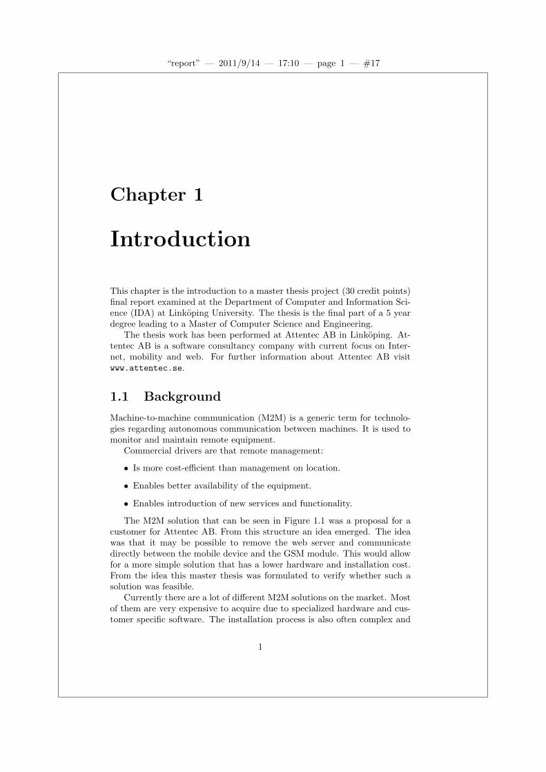
The M2M solution that can be seen in Figure 1.1 was a proposal for acustomer for Attentec AB. From this structure an idea emerged. The ideawas that it may be possible to remove the web server and communicatedirectly between the mobile device and the GSM module. This would allowfor a more simple solution that has a lower hardware and installation cost.From the idea this master thesis was formulated to verify whether such asolution was feasible.
Currently there are a lot of different M2M solutions on the market. Mostof them are very expensive to acquire due to specialized hardware and cus-tomer specific software. The installation process is also often complex and
1

“report” — 2011/9/14 — 17:10 — page 2 — #18
2 CHAPTER 1. INTRODUCTION
GSM
Module
PLC
Sensor 1
Sensor 2
Sensor 3
Valve 1
Valve 2
Valve 3
Web Server
Web
Interface
Figure 1.1: Original M2M solution. A PLC (Programmable Logic Con-troller) controls a set of valves and collects data from a set of sensors. ThePLC communicates with a web server via a GSM Module. The web serverthen communicates with both a web interface as well as a mobile device forrepresenting the values of the sensors and controlling the valves.
requires the infrastructure to be adopted to the system. This reduces thetarget group to large companies, and companies which heavily rely on M2Mto operate. By building more cost-efficient M2M architectures and imple-mentations new types of services may become available for new tiers ofequipment in new types of businesses. A further investigation of the con-cept of M2M can be found later in the report (in Section 2.1).
1.2 Purpose and Objective
By making M2M solutions more accessible with lower costs the amount offeasible applications using the technology will increase. Reducing the costalso expands the target group for M2M solutions since it will be less of aninvestment for the company. This will make more business areas able toutilize M2M and thus, in time, increase the need for the technology.
This thesis examines the possibility to develop a lightweight alternative toexisting M2M solutions using only common hardware devices and protocols.Here lightweight means that:
• It should have low cost for set-up and operation.
2

“report” — 2011/9/14 — 17:10 — page 3 — #19
1.3. LIMITATIONS 3
• It should be flexible so that the same core system may be used inseveral different application areas, with only minor adjustments.
• Both master and slave devices could potentially be mobile.
To accomplish this description of a lightweight system an Android tabletwill be used as both the back-end and user interface. The hardware for theslave device will be a Cinterion TC65T (see Section 2.3 for details). Thiswill satisfy all three criteria for a lightweight system. The choice of usingthese hardware devices was made before the thesis begun. An overview ofthe system can be seen in Figure 1.2.
Sensor-specific
interface3G/GPRS
User interface
UserAndroid tablet
Cinterion TC65T
Sensor
Cinterion TC65T
Sensor
Sensor
...
Figure 1.2: Overview of the system. The Cinterion TC65T devices (slaves)collects data from the connected sensors and forwards it to the Androidtablet (master). This allows the user to manage the sensors remotelythrough the tablet.
1.3 Limitations
Since this thesis does not focus on a specific use for M2M, application spe-cific design choices such as user interface, parameters and sensor-specificconfiguration is not considered. Energy consumption will also be of minorimportance for the implementation in this thesis. Performance and securityare aspects that have been considered to some extent but not as a primeconcern in the design and development stages.
3

“report” — 2011/9/14 — 17:10 — page 4 — #20
4 CHAPTER 1. INTRODUCTION
1.4 Intended Audience
This report is intended for an audience familiar with software developmentusing an object oriented language. Readers with a limited experience in soft-ware development may have trouble understanding the more complex partsof Chapter 2 (Technologies) and Chapter 3 (Android-based M2M platform).Anyone not familiar with software development will still be able to under-stand the main concepts of the thesis.
1.5 Thesis Overview
There are a total of five chapters in this thesis.Chapter 2 introduces the reader to the different technologies used in
this thesis. First off is M2M (Machine-to-machine communication), then thecommunication technologies used in the thesis. After that the used hardwareplatform (Cinterion TC65T), then Java ME (Micro Edition), and at last theAndroid platform.
Chapter 3 deals with the Android-based M2M platform implementedin the thesis. First the system requirements are listed. After that the majordesign choices of the design is discussed followed by an overview of thesystem. This chapter also describes the architecture of the implementedsystem and how both applications are used.
Chapter 4 contains the evaluation of the system described in Chapter3. The evaluation is based on several aspects such as reliability, security andperformance. An explanation of how the requirements are tested and whichof them that are fulfilled is also included.
Chapter 5 summarizes the thesis. It also discusses this thesis as wellas the future for this kind of M2M solution.
4
“report” — 2011/9/14 — 17:10 — page 5 — #21
Chapter 2
Technologies
2.1 Machine-to-machine Communication
This section aims to clarify the concept of machine-to-machine communica-tion (M2M).
2.1.1 Definition
M2M does not yet have a general definition, and therefore companies (andpeople) make up their own definitions which can be seen more as descriptionsuntil one standard definition is in place. The following description is, in myopinion, the most accurate. It is formulated by a company named Numerex[1]:
M2M communications consists of using a device (e.g., sensor,meter, etc.) to capture an ”event” (e.g., temperature, inven-tory level, location, environment status, etc.), relayed through anetwork (e.g., wireless, wired or hybrid) to an application (soft-ware program), translating the captured event into meaningfulinformation (e.g., there is a breach, corrosion requires attention,items need to be restocked, an accident has occurred, etc.).
Institute of Electrical and Electronics Engineers (IEEE) 802 LAN/MANStandards Committee has initiated a project for creating a standard forM2M [2]. This standard also includes definitions for commonly used con-cepts in the area. The latest revision (2011-06-30) for the M2M definitionis as follows:
Machine-to-Machine communication: This is informationexchange between user devices through a base station, or betweena device and a server in the core network through a Base Stationthat may be carried out without any human interaction.
5

“report” — 2011/9/14 — 17:10 — page 6 — #22
6 CHAPTER 2. TECHNOLOGIES
The European Telecommunications Standards Institute (ETSI) has alsostarted a Technical Committee in 2008 to develop standards for M2M [3, 4].
Even though the definitions differ they are all referring to the same corestructure where information is passed between a simple device such as asensor and a more competent back-end system over a network. Commonlythe information is collected in two or more layers to reduce the cost of thesimple devices. A general structure can be seen in Figure 2.1. The back-endsystem usually consists of a database, a user interface (like a web server)and a module for logic, control and data gathering. The data collectorscollect data from connected sensors and forward it to the back-end system.The sensors are usually connected to the data collectors using either someshort range wireless technology (WLAN, Bluetooth, Zig-Bee, etc.) or wiredconnection (LAN, I2C, analog, etc.). Communication between the back-end system and the data collectors are usually some long range wirelessconnection like GPRS, 3G or GSM.
Event-capturing sensors.
Data collection devices.
Database, logic and server for monitor
devices.
Screen, web interface, etc.
Monitor device(s)
Back-end system
Data collector 1
Sensor 1.1
Sensor 1.2
...
Data collector 2
Sensor 2.1
...
...
...
Figure 2.1: Hierarchy over a standard M2M solution.
Another interesting use of the M2M technology is to connect severaldifferent devices used in every-day life in a context-aware system. An genericexample of this has been implemented at a university in Zagreb, Croatia[5]. Their implementation uses the Android operating system for the clientdevices, but with the aim to extend support for other devices as well.
2.1.2 Background
Remote management of equipment has been around for a long time but theconcept of M2M was founded in late 1990:s with the idea of utilizing basestations instead of telephone lines for the communication. At that timehardware components were too expensive and neither the technology northe infrastructure were stable enough for such use. Today the needed tech-nologies are a lot more developed and costs for both hardware and mobilesubscriptions are at reasonable levels [4].
Mobile operators have a great interest in the development of M2M. The
6

“report” — 2011/9/14 — 17:10 — page 7 — #23
2.2. COMMUNICATION TECHNOLOGIES 7
market for phone subscriptions are getting saturated and machine commu-nication is a new opportunity for mobile operators [4]. For example, in2008 Telenor established a subsidiary called Telenor Connexion completelyfocusing on M2M [6].
2.1.3 Current M2M Applications
M2M is used in a lot of business areas to increase productivity and availabil-ity. There are essentially three common uses of the technology; production,monitoring and remote updates.
Production
Using M2M in production lets the manufacturers know when the construc-tion machines needs maintenance and/or a refill of parts [7]. The requestsmay be directed to either a person or a robot for refill and usually to a per-son for maintenance. For this application M2M can also be used to increaseor decrease the speed at which the machines are working. Most productionareas use M2M for said purposes. This increases efficiency and productivityof the production and the quality of the product.
Monitoring
Remote monitoring reduces the cost of maintenance and management a lotsince no person has to manually read the values from the devices or checkif they are working [7]. The monitored devices are also often spread outin a large area and/or in places difficult to reach. Thus utilizing M2M formonitoring is highly desirable since it removes the travelling time neededto check the devices. In 2009 a law was passed in Sweden saying that theelectricity meters in all housing has to be read on a monthly basis [8]. Tomake this feasible for electricity provider companies they use different M2Mtechnologies to acquire the data from the meters.
Updates
The use of electrical billboards has increased a lot for advertising purposes[9]. This is desirable since they can be updated to show different adver-tisements based on time of day and/or day of the week. It also allows forinstant updates of daily prices and offers.
2.2 Communication Technologies
This section gives a brief introduction in the communication protocols andstandards used in this thesis.
7

“report” — 2011/9/14 — 17:10 — page 8 — #24
8 CHAPTER 2. TECHNOLOGIES
2.2.1 Network Standards
The network standards describe the physical means for transferring mes-sages. In this thesis both GPRS and 3G are used for communication. GPRSis used by the slave device (Cinterion TC65T) to access the internet. 3Gis used in the master device for the same purpose. The reason why GPRSis used instead of 3G in the slave device is that Cinterion TC65T does notsupport 3G. In future versions of M2M-devices 3G will probably be used toincrease performance and decrease latency.
GPRS
General Packet Radio Service (GPRS) is an extension to Global System forMobile Communications (GSM) adding functionality for packet-switcheddata transfers [10]. GPRS is often called 2.5G.
3G
The third generation mobile telecommunications (3G) is a set of standardsused for telecommunications. Compared to GPRS it offers significantlyhigher bandwidth.
2.2.2 Communication Protocol
For the implemented system described in Chapter 3 the TCP/IP model isused for communication.
TCP/IP
The Transmission Control Protocol (TCP) and the Internet Protocol (IP)are usually used together along with a set of other protocols for communica-tion, forming a model. This model is often referred to as the TCP/IP model(or just TCP/IP) since these two protocols are the main protocols used.The model is based on four layers: Link Layer, Internet Layer, TransportLayer and Application Layer. Each layer will perform some actions on eachdata packet to send. For example the Internet Layer handles addressing,so it adds an IP header to each packet containing the IP address of thereceiver among other things. Most platforms supporting network communi-cation has built in support for the TCP/IP model which lets the applicationprogrammer focus on other aspects of the application.
2.3 Cinterion TC65T
This section describes the GSM module Cinterion TC65T used in the im-plementation.
8

“report” — 2011/9/14 — 17:10 — page 9 — #25
2.3. CINTERION TC65T 9
2.3.1 Cinterion Wireless Modules GmbH
Cinterion Wireless Modules GmbH is a supplier of M2M-capable deviceswith headquarters in Germany. Cinterion was the first company to providea M2M data module utilizing GSM in 1995. Since then they have beenone of the leading companies in the business of M2M devices with severalimportant innovations in the area. They have been the global market shareleader in cellular M2M devices every year since 2003. In 2009 they had aglobal market share of 26%, where the second largest had 23% [11].
2.3.2 Device Information
The TC65T module (Figure 2.2) is a GPRS capable M2M device. The actualmodel name is ”TC65”, and the ending ”T” means that it is mounted in aterminal. For the implementation part of this thesis the TC65T module isused as slave device.
The key features of the TC65: [12]
• Quad-band technology (850/900/1800/1900 MHz).
• High-speed data transfer using GPRS (class 12).
• JavaTMsupport, IMP-NG (see Section 2.4 for a description).
• Range of standard interfaces (I2Cbus, SPI bus, analogue-digital con-verter (ADC), serial, audio, 10 GPIOs and a SIM card interface).
• ARM7 processor.
• Integrated TCP/IP stack.
2.3.3 Internal Structure
The TC65T has mainly three modules; a Modem, a Java Machine and aRecordstore database. View Figure 2.3 for an overview.
Modem
The Modem module handles communication with the attached SIM card,GPIOs and the GSM network. The user may interact with the modemmodule with AT commands through the RS232 (COM) port.
Java Machine
The Java Machine in the TC65T supports the Java ME profile IMP-NG(Imformation Module Profile - Next Generation, see Section 2.4 for details).This allows for a relatively low development time for applications comparedto other devices utilizing C or Assembler for developing applications. AT
9

“report” — 2011/9/14 — 17:10 — page 10 — #26
10 CHAPTER 2. TECHNOLOGIES
Figure 2.2: Cinterion TC65T.
commands may be used to communicate with the Modem module. The JavaMachine implementation also has abstraction layers for common communi-cation channels like the RS232 port, Internet and GPIOs (General PurposeInputs/Outputs).
Recordstore Database
The Recordstore database is a very limited database used for its minimalspace requirement. It has an abstraction layer in the Java Machine thatonly supports storing arrays of bytes. This means that the application pro-grammer has to perform the conversion between the internal structures andbyte arrays.
2.4 Java Micro Edition
Java Micro Edition (ME) is a stripped down version of Java Standard Edi-tion (SE). It was originally created by Sun Microsystems (later acquired byOracle) to allow developers to make applications for small devices with lim-ited memory, display and power capacity [13]. Because of the wide spectrumof applications for Java ME it is divided into two base configurations andseveral profiles.
The two base configurations of Java ME are Connected Limited DeviceConfiguration (CLDC) which is intended for small limited devices and Con-nected Device Configuration (CDC) which is more versatile. Mobile Infor-
10

“report” — 2011/9/14 — 17:10 — page 11 — #27
2.5. ANDROID 11
Figure 2.3: Internal structure of the Cinterion TC65T. The Modem handlesthe SIM card and GSM/GPRS functionality. The Java Machine can runJava ME code and communicates with the modem through AT Commands.
mation Device Profile (MIDP) is an extended version of the CDLC used fordeveloping applications for mobile communication devices. MIDP is dividedinto three versions where 1.0 is CDLC extended with support for MIDletprogramming, GUI, persistent data storage, some network capability andsecurity. MIDP 2.0 extends MIDP 1.0 with the most important additionsbeing support for HTTPS, digital certificates and a small XML parser. Somefeatures added in the 3.0 version are IPv6, multiple network interfaces andauto-launch of MIDlets.
The profile used in Cinterion TC65T (Section 2.3) is Information ModuleProfile - Next Generation (IMP-NG) which is a strict subset of MIDP 2.0where all GUI components has been removed. This profiled is intended forsmall embedded network devices without display.
2.5 Android
The purpose of this section is to give the reader some basic understandingof the Android operating system.
Android is an operating system for smartphones and tablets. It is dis-tributed under an open license and is free to use. Some standard applicationslike SMS, mail, maps, contacts and calendar are shipped with the operat-ing system. Some manufacturers also include their own software in theirdevices. Application developers have access to the same APIs used by thestandard applications. Due to this, each application have the same priorityseen from the operating system:s point of view.
2.5.1 History
With the purpose to advance the open standards for hand held devices theOpen Handset Alliance (OHA) was formed in November 2007 by 34 compa-
11

“report” — 2011/9/14 — 17:10 — page 12 — #28
12 CHAPTER 2. TECHNOLOGIES
nies, led by Google. Along with the formation, OHA released Android, anoperating system targeting hand held devices. Android has been availablesince October 2008.
2.5.2 Android for the Application Programmer
Applications for Android is developed using the Java programming language.Instead of using the Java Virtual Machine (JVM) OHA created the DalvikVirtual Machine which works almost identical as the JVM. A plugin forEclipse [14] exists containing a lot of features to make developing for An-droid easier and more efficient. There are four application components forAndroid: activity, service, content provider and broadcast receiver. The fol-lowing descriptions for each of them are copied from the Android developerweb page [15].
Activity
An activity represents a single screen with a user interface. Forexample, an email application might have one activity that showsa list of new emails, another activity to compose an email, andanother activity for reading emails. Although the activities worktogether to form a cohesive user experience in the email applica-tion, each one is independent of the others. As such, a differentapplication can start any one of these activities (if the email ap-plication allows it). For example, a camera application can startthe activity in the email application that composes new mail, inorder for the user to share a picture.
Service
A service is a component that runs in the background to performlong-running operations or to perform work for remote processes.A service does not provide a user interface. For example, a ser-vice might play music in the background while the user is ina different application, or it might fetch data over the networkwithout blocking user interaction with an activity. Another com-ponent, such as an activity, can start the service and let it runor bind to it in order to interact with it.
Content provider
A content provider manages a shared set of application data.You can store the data in the file system, an SQLite database,on the web, or any other persistent storage location your appli-cation can access. Through the content provider, other applica-tions can query or even modify the data (if the content provider
12

“report” — 2011/9/14 — 17:10 — page 13 — #29
2.5. ANDROID 13
allows it). For example, the Android system provides a contentprovider that manages the user’s contact information. As such,any application with the proper permissions can query part ofthe content provider (such as ContactsContract.Data) to readand write information about a particular person.
Content providers are also useful for reading and writing datathat is private to your application and not shared.
Broadcast receiver
A broadcast receiver is a component that responds to system-wide broadcast announcements. Many broadcasts originate fromthe system-for example, a broadcast announcing that the screenhas turned off, the battery is low, or a picture was captured. Ap-plications can also initiate broadcasts-for example, to let otherapplications know that some data has been downloaded to thedevice and is available for them to use. Although broadcast re-ceivers don’t display a user interface, they may create a statusbar notification to alert the user when a broadcast event occurs.More commonly, though, a broadcast receiver is just a ”gate-way” to other components and is intended to do a very minimalamount of work. For instance, it might initiate a service to per-form some work based on the event.
13

“report” — 2011/9/14 — 17:10 — page 14 — #30
14 CHAPTER 2. TECHNOLOGIES
14

“report” — 2011/9/14 — 17:10 — page 15 — #31
Chapter 3
Android-based M2Mplatform
This chapter describes the design and implementation of the M2M systemdeveloped during this thesis. The system consists of a master device (toptwo layers in Figure 2.1) and a slave device (third layer in Figure 2.1).
3.1 Requirements
In this section all requirements on the implementation are listed. Since theimplementation is a ”Proof of Concept” the requirements are there to ensurethe right concepts are proven by the implemented system.
3.1.1 Structure of Requirements
Each requirement has a unique ID, an explanation and a priority. Thepriority will follow Table 3.1.
Table 3.1: Requirements priority.
Priority Description1 Main goal of the project. Has to be done.2 In the scope of the project but can be ignored if there is a risk
for them to interfere with fulfilling priority 1 requirements (e.g.for time reasons).
3 Not in the scope of the project and will be done after all priority1 and 2 requirements are fulfilled.
15

“report” — 2011/9/14 — 17:10 — page 16 — #32
16 CHAPTER 3. ANDROID-BASED M2M PLATFORM
3.1.2 Functional Requirements
All functional requirements for the implementation are listed in Table 3.2.
Table 3.2: Functional requirements.
ID Description Priority1 The system shall be implemented using a Master-Slave
architecture.1
2 The master can send messages to the slave when connec-tion is established.
1
3 The slave can send messages to the master when connec-tion is established.
1
4 Messages sent when connection is lost should be saved andsent when connection is reestablished.
1
5 The system shall be able to handle at least two slaves. 16 Slaves shall not contain master-specific software (IP ad-
dress et cetera).1
7 System shall be compatible with Android 2.2 or higher. 18 New slave shall be possible to add to the system without
updating master software.1
9 Communication between master and slave shall use GPRS. 110 Communication interface shall use IP. 111 The slaves shall support multiple connected sensors. 112 Restarting the master application should not remove mon-
itored slaves.2
13 The master application should have a simple user interface. 214 Slaves may be able to be updated remotely. 215 Slave parameters may be updated over the air. 216 Identified security issues shall be solved. 217 Communication interface may be compatible with >2.5G
networks.2
18 The android based master application shall be replaceablewith a PC based web server.
2
19 Slave parameters (sensor names, ranges, etc.) may be con-figurable via the server UI.
3
20 The master may be able to retrieve sensor values fromother sources (e.g. internet).
3
21 The master architecture shall provide a developer friendlyplatform for developing logic controlled events.
3
22 The slave may support sensors over I2Cbus. 323 The master application may be replaceable with a Google
based cloud service.3
24 The system shall be able to handle roaming networks. 3
16

“report” — 2011/9/14 — 17:10 — page 17 — #33
3.2. MAJOR DESIGN CHOICES 17
3.1.3 Non-functional Requirements
All non-functional requirements for the implementation are listed in Table3.3.
Table 3.3: Non-functional requirements.
ID Description Priority25 The slave software shall be developed using Eclipse. 126 All software shall be commented thoroughly and complex
design documented separately.1
27 All software developed shall be under revision control us-ing SVN, all releases shall be tagged and repository kepton Attentec AB’s servers.
1
28 Possible security issues identified during development shallbe documented.
1
3.2 Major Design Choices
In this section the major design choices are described. The implementa-tion aims to fulfil all priority 1 requirements while still being consideredlightweight as described in Section 1.2. Some priority 2 and 3 requirementswill be fulfilled if they do not risk the completion of more important tasks.
3.2.1 Android Platform
Even though the choice to use the Android platform was taken before thethesis started it is worth considering if this is indeed the most appropriatechoice for the system. The thesis is focused on a lightweight M2M solutionwith Android only as one of the possible options. Other options includeiOS on an iPad/iPhone and Windows/UNIX on a PC (with a web serverfor remote control).
Using a smartphone platform for the master device both ensures mobilityand allows the back-end and the user interface to be combined in one device.This greatly reduces the cost compared to using a stationary server witha web interface. It also requires less physical space and has less powerconsumption. The reason why Android was chosen over iOS is that it ismore accessible for developers as it requires no developer license.
Since the programming language for Android is Java, the code for theserver part of the master is easy to port to a PC if needed.
3.2.2 Terminal Module
To acquire a system fulfilling our description of lightweight, the terminalmodule need to be mobile and it needs to be as generic as possible in terms
17

“report” — 2011/9/14 — 17:10 — page 18 — #34
18 CHAPTER 3. ANDROID-BASED M2M PLATFORM
of possible applications. It should also preferably not be expensive and itshould be easy to develop to since that also lowers the cost. The CinterionTC65T module (see Section 2.3) fulfils all of these criteria and since it is alsoone of the most popular platforms for developing M2M solutions it has beenchosen as slave device in this thesis. Another reason for this choice is thatthe company at which the thesis work was done (Attentec AB) has a col-laboration with a distribution company for Cinterion called Acte SolutionsAB [16]. This made both the device and support for it easily accessible.
3.2.3 Communication Interface
For this implementation the communication protocol should be able to de-tect if messages are transferred properly, it should be a common protocoland it should be available on both platforms used. TCP/IP fulfils all ofthese criteria and since it is one of the most common protocols for datacommunication no other protocol is considered.
Since the communication between master and slave is a TCP/IP con-nection, using Java’s Socket class for handling the protocol is convenientsince it manages the protocol. This lets the application programmer focuson other aspects of the application. To establish connection between thetwo devices in the system one of them has to run as TCP/IP server. TheTCP/IP server waits for incoming connection from the TCP/IP client. Theclient device always has to initiate the connection. Either device may beTCP/IP server, and there are advantages and drawbacks with both setups.Low-cost subscription usually provide dynamic IP address and put the userbehind a firewall. This firewall blocks incoming connections which meansthat it cannot be the TCP/IP server. The dynamic IP address aspect is alsonot preferred for the TCP/IP server since that would make the IP addressable to change and the TCP/IP client has to connect to the new address.Requirements affecting the choice for communication interface are listed inTable 3.4.
Table 3.4: Requirements affecting the communication interface.
ID Description2 The master can send messages to the slave when connection is es-
tablished.3 The slave can send messages to the master when connection is es-
tablished.5 The system shall be able to handle at least two slaves.6 Slaves shall not contain master-specific software (IP address et
cetera).
18

“report” — 2011/9/14 — 17:10 — page 19 — #35
3.3. SYSTEM OVERVIEW 19
Advantages of Having the Master Device as TCP/IP Server
• Only the master device need to have a more expensive subscriptionwithout the operator’s firewall, and preferably with static IP.
• The slaves may send sensor updates at any time (assuming both de-vices are connecting to the network).
• No need for server to poll for sensor updates.
Advantages of Having the Slave Device as TCP/IP Server
• The master may send commands at any time (assuming both devicesare connecting to the network).
• Initial connection is a lot more simple since the user can enter the IPaddress to the slave device in the user interface.
Chosen Design
The slave device is the one usually sending updates and the best optionis therefore to let it be the TCP/IP client. Using the master device asTCP/IP server is also more beneficial for the user because only the masterdevice needs a more expensive subscription and the system is designed toallow several slaves to connect to the same master. The major drawback ofusing this design is that the slave needs to get the IP to the master in someway since the slave does not know the IP address to the master for the firstconnection. Some additional communication channel where the master canaddress the slave is needed. The TC65T has several wired inputs but sincethey are wired they do not fit the purpose. It also supports SMS which fitsperfectly since it is a long-range wireless technology where the master devicecan address the slave device.
3.3 System Overview
The system consists of one master application and one or more slave ap-plication(s). An overview with one slave can be seen in Figure 3.1. Moreslaves may be added and all slaves communicates with the same connectionservice in the master application (the system is only tested with a maximumof two slaves).
Figure 3.2 shows how the interaction between user, master and slave isdesigned to work.
3.3.1 Communication
As with all communication systems the communication has to be reliable.Messages should not be lost at any point. This is a bit tricky in this systemsince both devices are mobile and may lose connection at any time.
19

“report” — 2011/9/14 — 17:10 — page 20 — #36
20 CHAPTER 3. ANDROID-BASED M2M PLATFORM
Slave Application Master Application
UI Activities
SQLite
Database
Connection Service CommunicationAndControl
Sensor 1
Driver
Module
Database
Internal communication
Wireless channel
Sensor N
Driver
RecordStore
Database
AT-CommandListener
…
Sensor 1 Sensor N External module
Wired channel
…
Figure 3.1: Architecture of the implemented system. Sensor values arecaptured by the Sensor drivers and saved in the Recordstore. At each updatesession all saved sensor values are read by the Communication and Controland sent to the Connection Service using GPRS/IP and then stored in theSQLite database. The AT-Command Listener is used for capturing SMS-events and the UI Activities are used to interact with the user.
If connection is lost while a message is being sent both devices need to seethis and act accordingly to avoid losing messages. The system is designedto catch all losses of connection and save messages until the next time thedevice should send. The effect of this is that connections initialized whenconnection is absent will be skipped and all values saved. Losing connectionduring a message will have the same effect as not having connection at allfor the current message.
3.4 Master Application
The master application consists of three separate modules; a SQLite database,a section of user interface activities and a connection service. Most of thecommunication between the user interface activities and the connection ser-
20

“report” — 2011/9/14 — 17:10 — page 21 — #37
3.4. MASTER APPLICATION 21
Update session loop (repeating).
Master
applicatio
n
User
SMS with IP address to the master.
Initial connection request.
Notification that a slave has
connected.
Configuration (name and
update interval).
Configuration (name and
update interval).
Slave
applicatio
n
New slave added to
the list of slaves,
visible for the user.
Sensor updates (empty unless
sensor(s) has been added).
Configuration for new
sensors.
Configuration for a new
sensor. Can be sent any
number of times (even zero).
Can be sent at any time
during the update session
loop.
Wait for one update interval.
Figure 3.2: Communication between user, master and slave. When bothdevices are switched on, the slave is triggered by sending a SMS containingthe IP address to the master. The slave then tries to connect to that IPaddress. If the connection is successful the master will notify the user thata new slave has connected and the user may enter configuration informationfor it. The configuration information is sent to the slave which then entersthe update session loop. In the loop the slave sends all sensor values to themaster, then receives configuration for new sensors, and if transmission issuccessful it removes all sent sensor values.
21

“report” — 2011/9/14 — 17:10 — page 22 — #38
22 CHAPTER 3. ANDROID-BASED M2M PLATFORM
vice uses the database as channel. A hierarchy of the master applicationmay be seen in Figure 3.3.
The device used while developing is Samsung Galaxy Tab which is atablet running Android version 2.2.
UI Activities M2MMasterActivity
ViewSlaveActivity
CreateSensorActivity ViewSensorActivity
CreateSlaveActivity ConnectionService
SQLite database
Figure 3.3: Hierarchy of the master application.
3.4.1 User Interface Activities
Since the implementation is a proof-of-concept the user interface will onlysupport the required functional features and does not provide a high levelof usability.
M2MMasterActivity
M2MMasterActivity is the entrance activity and will therefore be startedwhen the application is started. When started, this activity also starts theConnection Service (see Section 3.4.2) and has menu options for stoppingand restarting the Connection Service. The activity shows the IP addressto the device it is running on since the user need to send that IP addressto the slave device as a SMS. A list with all connected slaves is presentedin the activity as well. If the user clicks on a slave the ViewSlaveActivitywill be started. A screenshot of M2MMasterActivity may be seen in Figure3.4a.
ViewSlaveActivity
When ViewSlaveActivity is started it requests the database row id of a slave.The slave description is fetched and all sensors associated with it are listed.Clicking on one of the sensors starts the ViewSensorActivity with currentslave’s IMEI (International Mobile Equipment Identity) and current sensors
22

“report” — 2011/9/14 — 17:10 — page 23 — #39
3.4. MASTER APPLICATION 23
name as parameters. A screenshot of ViewSlaveActivity may be seen inFigure 3.4b. The slave device represented in this screenshot has the nameSlave Device and has two connected sensors named Sensor 1 and Sensor2. The sensor type and update interval of each sensor may be seen as well.Clicking the menu button on the device brings up one menu option: Insertwhich starts the CreateSensorActivity.
(a) M2MMasterActivity. The top field isthe name of the application and below itis the IP to the device. The third fieldfrom the top is a list of all connected slaves.Each entry in the list has name and IMEIof the slave.
(b) ViewSlaveActivity. The top field is thename of the slave and below it is a list ofall sensors connected to that slave. Eachsensor has its name to the left and the typeof sensor and the update interval to theright.
Figure 3.4: Screenshots of M2MMasterActivity and ViewSlaveActivity.
ViewSensorActivity
ViewSensorActivity lists all values for the sensor with the input slave IMEIand sensor name. Each row in the list contains one value and the times-tamp at which time the value was sampled in the slave. A screenshot ofViewSensor-Activity may be seen in Figure 3.5a. The name of the sensorrepresented is Sensor 2 and it has logged 10 sensor values.
23

“report” — 2011/9/14 — 17:10 — page 24 — #40
24 CHAPTER 3. ANDROID-BASED M2M PLATFORM
(a) Screenshot of ViewSensorActivity. Thetop field is the name of the sensor and be-low is a list of all accumulated values forthat slave. Each value has a timestamp tothe left and a value to the right.
(b) CreateSensorActivity. Three fields forthe user to enter information and a confirmbutton.
Figure 3.5: Screenshots of ViewSensorActivity and CreateSensorActivity.
CreateSensorActivity
When creating a new sensor the user has to input information about it. Thefields are name, update interval and sensor type. These input parameters aresaved as an entry in the slave’s table in the SQLite database. The new entrygets a value in the ”Value type”-field for showing that it is the header-entryfor a new value. A screenshot may be seen in Figure 3.5b.
CreateSlaveActivity
The purpose of the CreateSlaveActivity is to set parameters for a new slaveconnected to the master. The parameters to set are name and update in-terval. These input parameters are saved as an entry in the table for sensorvalues in the SQLite database. The activity also shows a 60 seconds timerwhich begins when a new slave connects. The purpose of this timer is toallow the connection to time-out after that time and the slave does not have
24
“report” — 2011/9/14 — 17:10 — page 25 — #41
3.4. MASTER APPLICATION 25
to wait for an infinite time. This matter is further explained in Section 4.6.
3.4.2 Connection Service
The connection service is used for communicating with the slave devices. Itis initiated, and can be stopped, by the M2MMasterActivity. While running,the connection service holds a port open for incoming connection requests.When a slave connects, it handles all communication and performs differenttasks depending on the input from the slave and the state of the master.
3.4.3 SQLite Database
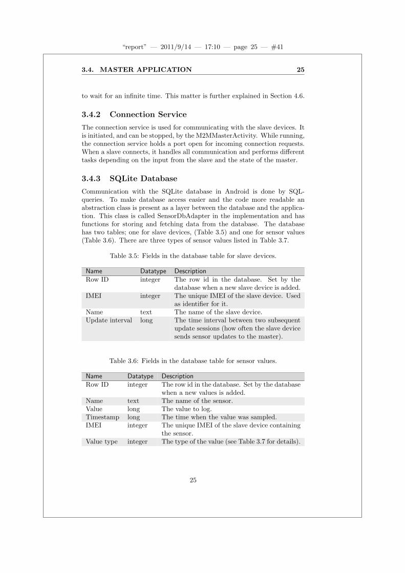
Communication with the SQLite database in Android is done by SQL-queries. To make database access easier and the code more readable anabstraction class is present as a layer between the database and the applica-tion. This class is called SensorDbAdapter in the implementation and hasfunctions for storing and fetching data from the database. The databasehas two tables; one for slave devices, (Table 3.5) and one for sensor values(Table 3.6). There are three types of sensor values listed in Table 3.7.
Table 3.5: Fields in the database table for slave devices.
Name Datatype DescriptionRow ID integer The row id in the database. Set by the
database when a new slave device is added.IMEI integer The unique IMEI of the slave device. Used
as identifier for it.Name text The name of the slave device.Update interval long The time interval between two subsequent
update sessions (how often the slave devicesends sensor updates to the master).
Table 3.6: Fields in the database table for sensor values.
Name Datatype DescriptionRow ID integer The row id in the database. Set by the database
when a new values is added.Name text The name of the sensor.Value long The value to log.Timestamp long The time when the value was sampled.IMEI integer The unique IMEI of the slave device containing
the sensor.Value type integer The type of the value (see Table 3.7 for details).
25
“report” — 2011/9/14 — 17:10 — page 26 — #42
26 CHAPTER 3. ANDROID-BASED M2M PLATFORM
Table 3.7: Value types for sensor values.
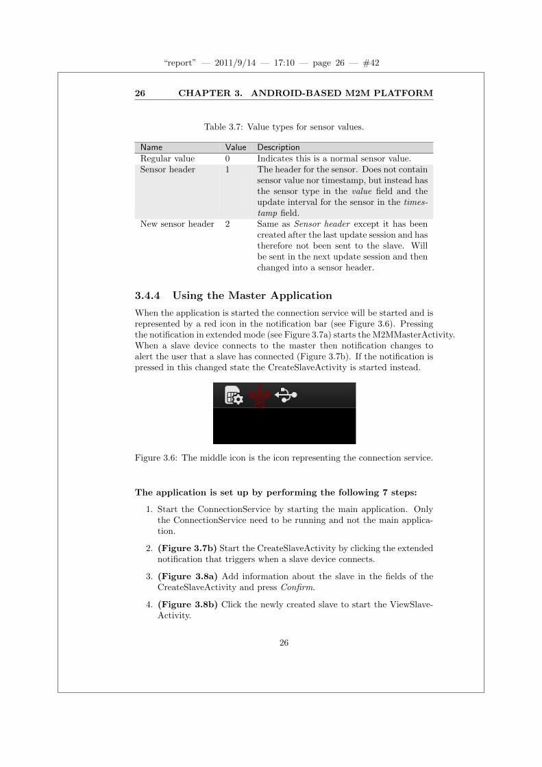
Name Value DescriptionRegular value 0 Indicates this is a normal sensor value.Sensor header 1 The header for the sensor. Does not contain
sensor value nor timestamp, but instead hasthe sensor type in the value field and theupdate interval for the sensor in the times-tamp field.
New sensor header 2 Same as Sensor header except it has beencreated after the last update session and hastherefore not been sent to the slave. Willbe sent in the next update session and thenchanged into a sensor header.
3.4.4 Using the Master Application
When the application is started the connection service will be started and isrepresented by a red icon in the notification bar (see Figure 3.6). Pressingthe notification in extended mode (see Figure 3.7a) starts the M2MMasterActivity.When a slave device connects to the master then notification changes toalert the user that a slave has connected (Figure 3.7b). If the notification ispressed in this changed state the CreateSlaveActivity is started instead.
Figure 3.6: The middle icon is the icon representing the connection service.
The application is set up by performing the following 7 steps:
1. Start the ConnectionService by starting the main application. Onlythe ConnectionService need to be running and not the main applica-tion.
2. (Figure 3.7b) Start the CreateSlaveActivity by clicking the extendednotification that triggers when a slave device connects.
3. (Figure 3.8a) Add information about the slave in the fields of theCreateSlaveActivity and press Confirm.
4. (Figure 3.8b) Click the newly created slave to start the ViewSlave-Activity.
26

“report” — 2011/9/14 — 17:10 — page 27 — #43
3.5. SLAVE APPLICATION 27
5. (Figure 3.8c) Press the menu button to bring up the menu optionInsert and press it to start the CreateSensorActivity and insert a newsensor.
6. (Figure 3.8d) Fill in the fields for the new sensor and click Confirmto create the sensor and return to the ViewSlaveActivity.
7. (Figure 3.9a) The new sensor may now be seen in the ViewSlave-Activity. Clicking the sensor will show the log of values for it (Figure3.9b and 3.9c).
(a) Standard (b) Slave connected
Figure 3.7: Notifications in extended mode. The field just below the ”Noti-fications” field is representing the LightweightM2M application. In Figure3.7a the standard notification is shown and in Figure 3.7b a client has con-nected which changes the notification, and the IP to the slave is shown.
3.5 Slave Application
The tasks of the slave application is to collect and log values from all con-nected and configured sensors and send them to the master. The datacollection rate can be set individually for each sensor and is either decidedby the implemented driver for that sensor type or by the user. All valueslogged are sent to the master with an interval decided by the user (the up-date interval set in the CreateSlaveActivity) and then deleted at the slave
27

“report” — 2011/9/14 — 17:10 — page 28 — #44
28 CHAPTER 3. ANDROID-BASED M2M PLATFORM
(a) CreateSlaveActivity. The number inthe top (here 25 seconds) is a countdowntimer showing how long the user has toenter the fields and confirm. Below it is thetwo fields for name and update interval,and lastly a confirm button.
(b) M2MMasterActivity with one slave de-vice added. The top field is the name ofthe application and below it is the IP tothe device. The third field from the top isa list of all connected slaves. Each entry inthe list has name and IMEI of the slave.
(c) ViewSlaveActivity with no sensorsadded for the slave. Only the name ofthe slave is shown and the list of sensorsis empty.
(d) CreateSensorActivity. Three fields forthe user to enter information and a confirmbutton.
Figure 3.8: Using LightweightM2M, steps 1 to 4 of 7.
28

“report” — 2011/9/14 — 17:10 — page 29 — #45
3.5. SLAVE APPLICATION 29
(a) ViewSlaveActivity with one sensor inthe list of sensors.
(b) ViewSensorActivity with two sensorvalues.
(c) ViewSensorActivity with ten sensorvalues.
Figure 3.9: Using LightweightM2M, steps 5 to 7 of 7.
29

“report” — 2011/9/14 — 17:10 — page 30 — #46
30 CHAPTER 3. ANDROID-BASED M2M PLATFORM
end. This means that only the values since the last successful transmissionare stored locally at the slave. If no transmission is successful, all values willbe stored in the slave. The storing of values when the connection is downis limited to the memory of the slave device. There are currently no errorhandling if the memory is not sufficient, but that should only happen invery rare cases. A time diagram example of this where no connection erroroccurs may be seen in Figure 3.10.
Time S1 (3s) S2 (4s) Slave database Update session (10s)
0 0 0 S1:0, S2:0 Send the sensors configuration to slave
1 S1:0, S2:0
2 S1:0, S2:0
3 1 S1:0, S2:0, S1:1
4 1 S1:0, S2:0, S1:1, S2:1
5 S1:0, S2:0, S1:1, S2:1
6 2 S1:0, S2:0, S1:1, S2:1, S1:2
7 S1:0, S2:0, S1:1, S2:1, S1:2
8 2 S1:0, S2:0, S1:1, S2:1, S1:2, S2:2
9 3 S1:0, S2:0, S1:1, S2:1, S1:2, S2:2, S1:3
10 Send: S1:0, S2:0, S1:1, S2:1, S1:2, S2:2, S1:3
11
12 4 3 S1:4, S2:3
13 S1:4, S2:3
14 S1:4, S2:3
15 5 S1:4, S2:3, S1:5
16 4 S1:4, S2:3, S1:5, S2:4
17 S1:4, S2:3, S1:5, S2:4
18 6 S1:4, S2:3, S1:5, S2:4, S1:6
19 S1:4, S2:3, S1:5, S2:4, S1:6
20 5 S2:5 Send: S1:4, S2:3, S1:5, S2:4, S1:6
Figure 3.10: Timeline for a typical use scenario. S1 and S2 are sensors andfor demonstration purposes they are represented by counters, increasingtheir value each time they are read.
At start up, the application fetches configuration information (such asIP address to the master) from the Recordstore database. The applicationthen enters the update session loop which is the state where the applicationgathers data from the sensors and sends it to the master at a given interval.If no configuration information is found in the Recordstore database theapplication waits for a SMS containing a valid IP address. When such aSMS is received it connects to that IP address (which should be the addressof the master device) to fetch configuration and if configuration informationis received it enters the update session loop. A received SMS containing thetext ”reset” will reset the application, deleting all records in the database.The application will then wait for a SMS containing an IP address again. Aflow chart of the events may be seen in Figure 3.11.
30
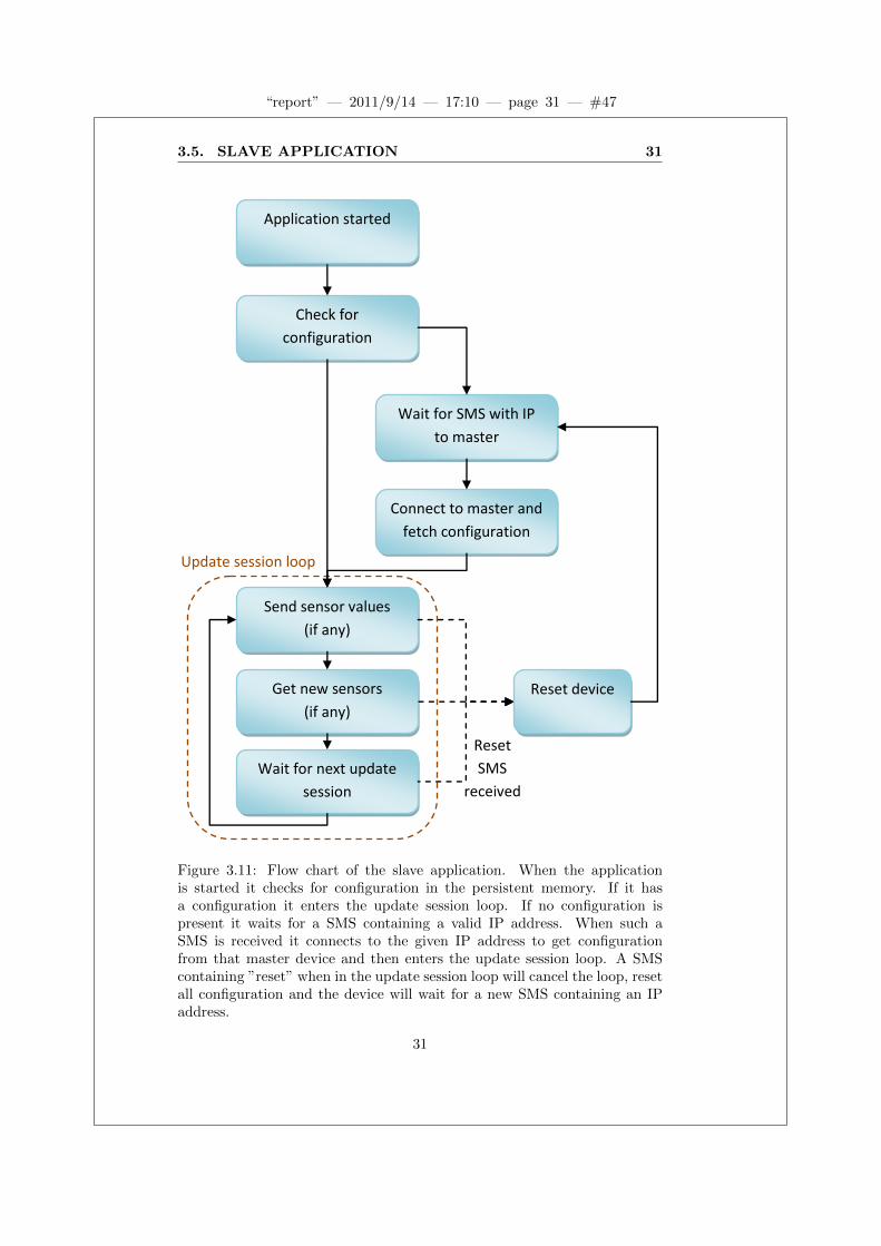
“report” — 2011/9/14 — 17:10 — page 31 — #47
3.5. SLAVE APPLICATION 31
Check for
configuration
Connect to master and
fetch configuration
Wait for SMS with IP
to master
Send sensor values
(if any)
Get new sensors
(if any)
Wait for next update
session
Reset
SMS
received
Reset device
Application started
Update session loop
Figure 3.11: Flow chart of the slave application. When the applicationis started it checks for configuration in the persistent memory. If it hasa configuration it enters the update session loop. If no configuration ispresent it waits for a SMS containing a valid IP address. When such aSMS is received it connects to the given IP address to get configurationfrom that master device and then enters the update session loop. A SMScontaining ”reset” when in the update session loop will cancel the loop, resetall configuration and the device will wait for a new SMS containing an IPaddress.
31
“report” — 2011/9/14 — 17:10 — page 32 — #48
32 CHAPTER 3. ANDROID-BASED M2M PLATFORM
3.5.1 Structure of the Slave Application
The classes in the slave application are described here. The architecture ofthe system can be seen in Figure 3.1.
CommunicationAndControl
This is the entry class for the slave application. It handles the flow ofevents in the application and all GPRS communication with the master.The CommunicationAndControl class extends MIDlet which lets the oper-ating system control the application through some standard methods thathave to be present, namely startApp(), destroyApp() and pauseApp().The startApp() method is called when the operating system starts the ap-plication, and likewise the destroyApp() is called when the application isshut down. These methods contain code for initiating the application andcleaning up for shut down, respectively. The pauseApp() method is notused in this implementation.
When called, the startApp() method creates a new instance of the Com-municationAndControl class and starts it in a new thread. This is possiblesince the class implements the Runnable interface which is a standard Javainterface supplying the run() method. This enables the class to be started,performing the run() method either in the same thread as the caller or ina new thread. The reason for starting the CommunicationAndControl classin a new thread is to not steal the calling thread from the operating system.By doing this the operating system is still able to call the other standardmethods if necessary.
The class also implements the BearerControlListener interface whichgives methods for observing the GPRS state of the device.
ATCommandListener
AT Commands are used to access features of the Cinterion TC65 not sup-ported by the Java ME implementation. In this application AT Commandsare used to handle the SMS functionality.
RecordStoreManager
Java ME has a class used for persistent storage called RecordStore. TheRecordStore can only handle byte[] and therefore an abstraction layerabove it is useful. The RecordStoreManager is that abstraction layer andprovides store and fetch functions useful for the slave application.
AbstractSensor
The AbstractSensor class is a class helping the developing of other sensordriver classes. New sensor classes should inherit from it and only overridethe method for fetching data from the physical sensor. The superclass is
32

“report” — 2011/9/14 — 17:10 — page 33 — #49
3.5. SLAVE APPLICATION 33
integrated in the application, so new subclasses of it are treated in the sameway and no modifications in other classes are needed.
3.5.2 Using the Slave Application
Since the application is running in an embedded system without any externalway of interacting with it except for some standard communication portsthe slave application has no interfaces for direct interaction. All interactionis through the master device. There are two communication channels; SMSand IP. SMS is used to receive the IP address to the master and to reset thedevice. These two commands are the only two available. Interaction usingIP is done by the master device. The user can only interact with the masterdevice which then communicates with the slave to perform the requestedactions.
33

“report” — 2011/9/14 — 17:10 — page 34 — #50
34 CHAPTER 3. ANDROID-BASED M2M PLATFORM
34

“report” — 2011/9/14 — 17:10 — page 35 — #51
Chapter 4
Evaluation
In this chapter the implementation is evaluated.
4.1 Requirement Verification
To see if the implemented system matches the intended requirements werevisit each requirement from Chapter 3 in Table 4.1, Table 4.2 and Table4.3.
The following list contains the tests for each requirement. Each test isinitiated by starting both devices and then sending a SMS containing themaster’s IP address to the slave. The slave then connects to the master anddummy values for each configuration field is entered, along with a dummysensor. The system in this state is here called running.
• Test 1 (requirement 2, 3, 15 and 19): Verify that the masterapplication gets updates from the slave device while the system isrunning.
• Test 2 (requirement 4): Tested by shutting down the Connection-Service in the master while the system is running. This makes theslave device unable to connect to the master since it does not acceptincoming connections. Restarting the ConnectionService lets the de-vices communicate again. Verify that all expected values are presentin the master after one successful update session.
• Test 3 (requirement 5, 8): When the system is running, a SMSwith the master’s IP is sent to a second slave device. The rest of theinitiation process is done for this second device as well. Verify that allexpected values are present in the master.
• Test 4 (requirement 6): The system is initiated with another deviceas master device. Verify that the system behaves as expected.
35

“report” — 2011/9/14 — 17:10 — page 36 — #52
36 CHAPTER 4. EVALUATION
Table 4.1: Functional requirements verification, part 1 of 2.
ID Description PriorityComment Fulfilled
1 The system shall be implemented using a Master-Slavearchitecture.
1
Fulfilled by the chosen design. Yes2 The master can send messages to the slave when connec-
tion is established.1
Tested and working. Yes3 The slave can send messages to the master when connec-
tion is established.1
Tested and working. Yes4 Messages sent when connection is lost should be saved and
sent when connection is restored.1
Tested and working. Yes5 The system shall be able to handle at least two slaves. 1
Tested with 1 and 2 slaves and working. Yes6 Slaves shall not contain master-specific software (IP ad-
dress et cetera).1
A slave can be connected to any master. Tested with twodifferent master devices and should work with any otherin theory.
Yes
7 System shall be compatible with Android 2.2 or higher. 1System is designed for Android 2.1 and tested with An-droid 2.1 and 2.2. The system should work with laterversions of Android as well since Android is backwardscompatible, this is not tested though.
Yes
8 New slave shall be possible to add to the system withoutupdating master software.
1
Tested and working. Yes9 Communication between master and slave shall use
GPRS.1
Slaves use GPRS for communication. Yes10 Communication interface shall use IP. 1
IP is the used protocol. Yes11 The slaves shall support multiple connected sensors. 1
Tested with 0 to 8 virtual sensors and working. Yes12 Restarting the master application should not remove mon-
itored slaves.2
The master application uses the SQLite database in An-droid which is persistent so a restart will not remove data.Tested and working.
Yes
36

“report” — 2011/9/14 — 17:10 — page 37 — #53
4.1. REQUIREMENT VERIFICATION 37
Table 4.2: Functional requirements verification, part 2 of 2.
ID Description PriorityComment Fulfilled
13 The master application should have a simple user inter-face.
2
A simple user interface supporting the functionality ispresent.
Yes
14 Slaves may be able to be updated remotely. 2The slave software cannot be updated remotely in thecurrent version.
No
15 Slave parameters may be updated over the air. 2IP is sent as SMS. Slave name, update interval andsensor parameters are set from the master device usingGPRS.
Yes
16 Identified security issues shall be solved. 2Security has not been considered during development. No
17 Communication interface may be compatible with>2.5G networks.
2
Not tested due to lack of compatible hardware. Shouldwork in theory since Java’s abstraction layers for IP-communication is used.
Probably
18 The android based master application shall be replace-able with a PC based web server.
2
A new master application using the same communica-tion interface for communicating with the slave(s) maybe implemented and should work. Not tested.
Probably
19 Slave parameters (sensor names, ranges, etc.) may beconfigurable via the server UI.
3
Tested and working. Yes20 The master may be able to retrieve sensor values from
other sources (e.g. internet).3
Not implemented. No21 The master architecture shall provide a developer
friendly platform for developing logic controlled events.3
Not implemented. No22 The slave may support sensors over I2Cbus. 3
Should work but not tested due to lack of hardware.Requires a new sensor driver to be added in the slave.
Probably
23 The master application may be replaceable with aGoogle based cloud service.
3
No support implemented. No24 The system shall be able to handle roaming networks. 3
Roaming networks are handled in lower abstraction lay-ers in the devices and should not affect the implementedsystem. Not tested.
Probably
37

“report” — 2011/9/14 — 17:10 — page 38 — #54
38 CHAPTER 4. EVALUATION
• Test 5 (requirement 11): More dummy sensors are added, one ata time up to 8 sensors, when the system is running. Verify that allvalues for all sensors are present in the master.
• Test 6 (requirement 12): Restarting the device running the masterapplication when the system is running. Verify that all sensor valuescaptured during the restart time is stored in the slave device andtransferred during the following successful update session.
Requirement 1, 7, 9, 10 and 13 are fulfilled but not connected to a specifictest. Their description is enough for verification. Requirements that are notfulfilled are not tested since the software does not intend to support any ofthem.
Table 4.3: Non-functional requirements verification.
ID Description PriorityComment Fulfilled
25 The slave software shall be developed using Eclipse. 1Eclipse has been used. Yes
26 All software shall be commented thoroughly and complexdesign documented separately.
1
Code is commented and design is documented in this re-port.
Yes
27 All software developed shall be under revision control us-ing SVN, all releases shall be tagged and repository kepton Attentec AB’s servers.
1
Mecurical has been used instead of SVN, but for the samepurpose and with the same result so this requirement isconsidered fulfilled.
Yes
28 Possible security issues identified during developmentshall be documented.
1
Security issues are documented in Section 4.4 of this re-port.
Yes
4.2 System Viability
The objective of this thesis work is to examine the possibility of develop-ing a lightweight alternative to existing M2M solutions using only commondevices and protocols. A system with desired properties has been imple-mented and therefore the short answer to the initial question is: Yes, it ispossible. The implemented system is though very limited in several respects(mainly security and performance). Due to this it can not give a practicalverification whether more advanced applications such as security- and/ortime-critical systems can be built in the same manner. It can, however,
38

“report” — 2011/9/14 — 17:10 — page 39 — #55
4.3. RELIABILITY 39
serve as a practical base that can be studied and potentially extended withmore advanced aspects.
4.3 Reliability
As described in Section 3.3.1, the system is designed to handle loss of com-munication. This is one of the main aspects for this thesis. In testing,the implemented functionality for storing lost messages and resending themworks fine. Whenever connection is lost, both devices simply discards allmessages received during the current transmission. The master device thenreturns to the state for waiting for connections and the slave device will waitfor the next time it is supposed to send.
4.4 Security
The implemented system is only intended for verifying some basic func-tionality of a lightweight M2M solution in a protected environment andtherefore does not consider security issues. If a similar system should bedeveloped for a real application then security will probably (depending onthe application) be of very high priority. Both the TC65T and the Androidplatform supports HTTPS, which is a secure version of HTTP, which inturn is an abstraction of TCP/IP. Since TCP/IP is the used protocol forthis implementation a further development of the system using HTTPS forcommunication between master and slave(s) should be quite feasible.
In its current state security can be breached in numerous ways. For ex-ample any device may connect to the master. If the communication interfaceis known the connected device may pretend to be a slave device and starvethe real slave devices by flooding the master.
Other than the GPRS/IP communication the system does also have asecurity issue with the SMS functionality. The slave is designed to onlylisten to two different SMS commands: ”reset” and valid IPv4 addresses.Since the slave does not check who sent the SMS and no authentication isdone, a SMS sent from anywhere containing a valid IP address will make theslave connect to that IP, and likewise a SMS containing ”reset” will resetthe device. The only thing required to breach security in this way is thetelephone number to the slave and a device that is able to send SMS.
4.5 Performance
The system is tested with two slave devices but the architecture is designedto work with arbitrary number of slaves. There is no theoretical maximumfor this other than the memory limitations on the master device and thebandwidth offered by the GPRS connection. In the same way there is notheoretical limit on the number of sensors connected to a slave. The number
39

“report” — 2011/9/14 — 17:10 — page 40 — #56
40 CHAPTER 4. EVALUATION
of input ports is limited, but a port may be shared by several sensors if someexternal device collects data from each of those sensors and forwards it tothe slave device through a single port. The limit of the system is insteadthat only one slave at a time may be connected to the master since all slavesconnect to the same TCP port. This means that the limiting factor is thefrequency and length of the messages.
4.5.1 Performance Tests
A set of tests has been done to measure the time for each update session,where a update session is the event of preparing and transmitting all sensorvalues collected since the last successful update session. For the test 30update sessions for each configuration are measured and the average of themis presented. Virtual sensors are used during testing. The virtual sensorsare separate threads that give dummy values at a fixed frequency.
In Figure 4.1 each test has a different number of virtual sensors accordingto their X-axis. When no sensor values are sent only some bytes for synchro-nizing are sent between the master and the slave. This means that for theconfiguration without sensor values (test 0 in Figure 4.1) the only timingoverhead is the time it takes for GPRS to connect. The figure shows thatmessages with values up to 8 sensor values take about the same amount oftime to send. This indicates that also for those configurations the majorityof the time is the set-up time of the GPRS connection.
Tests were also done with only a single virtual sensor giving all sensorvalues. The update session time for these tests can be seen in Figure 4.2.The difference between 1 and 8 sensor values is insignificant compared tothe difference for higher values. One explanation for this behaviour is thatfor larger messages the connection may be interrupted a lot by the threadrunning the virtual sensor and therefore the time for the update sessionsincreases. Another interesting observation is that 8 values takes about thesame amount of time with 1 and with 8 virtual sensors. This means thatthe extra 7 threads does not slow the system down. Here the test with morethreads does have a higher performance, but this is probably due to havingtoo few test samples.
To see the scaling for even higher number of values Figure 4.3 showsthe update session time for 1 sensor giving 40 values and also the updatesession time if another similar sensor is added. This shows almost a doublingin time, and considering earlier observations that the GPRS connection timeis pretty constant at 6-7 seconds the time for the actual data handling andtransfer is more than doubled.
The virtual sensors used in this test to measure the time for 25, 40 and80 values update their values every second while the other configurationsuse longer time intervals. This is for practical reasons (the test would taketoo long to perform for higher values). The sensor frequency may affect theresults since a higher frequency of the sensor may interfere more with the
40

“report” — 2011/9/14 — 17:10 — page 41 — #57
4.5. PERFORMANCE 41
5000
6000
7000
8000
9000
10000
0 1 2 3 4 8
Tim
e in
mill
ise
con
ds
Number of sensors giving one value per update session each
Update session time, multiple sensors
Figure 4.1: Update session time, multiple sensors. The X-axis representseach measured configuration and the Y-axis the average time for one updatesession in milliseconds. The tests are performed with one virtual sensor pervalue (so test 3 has three virtual sensors giving one value each per updatesession).
0
2000
4000
6000
8000
10000
12000
14000
16000
18000
1 8 15 25 40
Tim
e in
mill
ise
con
ds
Number of sensor values per update session
Update session time, one sensor
Figure 4.2: Update session time, one sensor. The X-axis represents eachmeasured configuration and the Y-axis the average time for one updatesession in milliseconds. Each test uses a single virtual sensor for all sensorvalues.
41

“report” — 2011/9/14 — 17:10 — page 42 — #58
42 CHAPTER 4. EVALUATION
0
5000
10000
15000
20000
25000
30000
35000
1 2
Tim
e in
mill
ise
con
ds
Number of sensors giving 40 values per update session each
Update session time, 40-value sensors
Figure 4.3: Update session time, 40-value sensors. The X-axis representseach measured configuration and the Y-axis the average time for one updatesession in milliseconds.
thread handling the update session.In Table 4.4 some examples of what the system should manage can be
seen. These values are a theoretical interpretation of the test values fromprevious tests. The purpose of them is to give an estimate of the perfor-mance. The values have some margin compared to the theoretical maxcomputed from the tests to allow for some practical variations.
Table 4.4: Theoretical number of devices the system can handle based ontesting. The first column represent the number of sensors connected toeach slave. The second column represent the frequency at which the sensorsare read. The third column represent the number of slaves connected tothe master. The fourth column represents three frequency of the updatesessions.
Sensors per slave Sensor update interval Slaves Slave update interval1 1 second 1 9 seconds5 30 seconds 10 2 minutes2 2 minutes 180 30 minutes10 30 minutes 100 17 minutes
Optimizations can probably be done to decrease the time for longer mes-sages but the time for GPRS to connect can not be neglected. Future appli-cations using this core structure may utilize 3G instead of GPRS to greatly
42

“report” — 2011/9/14 — 17:10 — page 43 — #59
4.6. TIME-OUTS 43
decrease the time to connect and send messages.
4.6 Time-outs
When the slave connects to the master it cannot know whether it will geta response or not. The IP address may be false or the master may be shutdown. This problem exists for most (maybe all) client-server connections.The common solution, which is also used here, is to have a time-out addedto the connection request. When the time-out is reached the client stopswaiting for a response and continues its execution. The master has a similartime-out since connection may also be lost during an update session. Thereare two different time-outs used for the connection.
• First connection time-out is used in the slave when it does nothave any configuration and connects to the master. The purpose ofthis time-out is to give the user time to enter the name and the updateinterval for the slave. The time-out is set to 65 seconds. If no responsefrom the master is received in time the slave will wait for 60 secondsand then try to connect again.
• Regular connection time-out is 15 seconds and is used for all con-nection occasions in the master and all except for the first in the slave.
Common for both time-outs are that no effort is put into finding theperfect values for them simply because the implementation in this thesisdoes not target a specific application. In a real application these values willprobably make a significant difference and the regular connection time-outmay be split into several different time-outs.
43

“report” — 2011/9/14 — 17:10 — page 44 — #60
44 CHAPTER 4. EVALUATION
44
“report” — 2011/9/14 — 17:10 — page 45 — #61
Chapter 5
Summary and Conclusions
M2M is a fast growing technology and many businesses are utilizing it forremote management of equipment. By developing a more cost-efficient M2Marchitecture the technology may become available in new business areas andnew types of services may arise. Added mobility also increases the numberof possibilities with the technology.
This thesis examines the possibilities for a new M2M architecture us-ing an Android platform as both back-end server and user interface. Thisarchitecture greatly increases the cost-effectiveness and mobility while lim-iting the performance. The architecture developed is intended as a generalarchitecture to be used as a core when designing application-specific M2Msystems and therefore takes no account of application-specific parameters.
The developed system is not suitable for large scale applications wherelots of nodes should be monitored. Instead the intention is that this ar-chitecture should be used to enable new services that require small-scalemonitoring and/or control.
The hardware platforms used in this thesis has been chosen before thethesis started. Due to this there is a risk that the implementation has beenaffected by the functionality of these platforms. The use of requirements hasreduced this risk since they were listed before any development had started(and therefore the knowledge about the platforms were limited in terms ofprogramming). However, since not all of the priority 2 and 3 requirementsare fulfilled the platforms may affect the possible implementation of someof these.
Most systems developed today have security as a high priority and there-fore it may have been better to consider security, leading to some choices inthe implementation. If the communication between master and slave usedthe HTTPS protocol instead of standard TCP/IP, an added level of secu-rity would have been present. This would probably have been more timeconsuming and would probably mean that some other part of the imple-mentation would have been left out but the results may have been of more
45

“report” — 2011/9/14 — 17:10 — page 46 — #62
46 CHAPTER 5. SUMMARY AND CONCLUSIONS
interest.The system implemented in this thesis is working and gives a practi-
cal indication that it is possible to develop M2M applications using onlycommon hardware devices and protocols. It also demonstrates that such asystem can be developed in a reasonable time. The use of general-purposeslave devices makes this system possible to use in a lot of different applica-tion areas and the mobility of the Android platform even further increasesthe possibilities.
5.1 Future Work
There are a lot of features that can be added to a system like the onedescribed in this thesis. The most important ones regard security and relia-bility since those are probably the most critical if a system like this shouldbe used in a real application. The protocol used for communication needsto be revisited as well. This thesis only aims to prove that a system thatmeets the requirements for a lightweight M2M solution can be implemented.
Performance will be increased without any effort from the developer since3G/4G will soon be standard for the kind of hardware platforms used. Thetablets will have increased performance as well. Using a standard platformfor the master device (Android, iOS, Windows Phone, et cetra) gives alot of possibilities for the user interface so that should never have to be alimiting factor for an application. Currently there are standard componentsfor different graphical views, like diagrams and map views.
46

“report” — 2011/9/14 — 17:10 — page 47 — #63
Bibliography
[1] Numerex. Numerex homepage. http://www.numerex.com/, accessedJune 2011.
[2] Hanan Ahmed and Erik Colban. Proposal for M2M device defini-tion on SRD. Technical report, IEEE 802.16’s Machine-to-Machine(M2M) Task Group, http://www.ieee802.org/16/m2m/index.html,June 2011.
[3] ETSI. Machine to Machine Communications. http://www.etsi.org/website/technologies/m2m.aspx, accessed June 2011.
[4] Mattias Wide and Urban Wicklander. M2M redo for genombrott. InElektroniktidningen, volume 2, pages 24–25. http://etn.se/, 2010.
[5] Matko Kuna, Hrvoje Kolaric, Iva Bojic, Mario Kusek and Gordan Jezic.Android/OSGi-based Machine-to-Machine Context-Aware System. InTelecommunications (ConTEL), Proceedings of the 2011 11th Interna-tional Conference, pages 95–102, Graz, Austria, June 2011. IEEE.
[6] Telenor Connexion. About Telenor Connexion. http://www.
telenorconnexion.com/about-us, accessed June 2011.
[7] Ephraim Schwartz. When Machines Speak. In InfoWorld, volume 43,page 20. InfoWorld Media Group, Inc., http://books.google.com/
books?id=2TkEAAAAMBAJ&pg=PA20&dq=#v=onepage&q&f=false, 2003.
[8] Maingate. Automatic Meter Reading. http://www.maingate.se/
automatic-meter-reading.aspx, accessed August 2011.
[9] Commitva Technology. Billboard Monitoring. http://corp.
commtiva.com/Solutions.aspx?ItemID=175, accessed August 2011.
[10] ETSI. GPRS. http://www.etsi.org/WebSite/Technologies/gprs.
aspx, accessed September 2011.
[11] Cinterion Wireless Modules GmbH. Cinterion Company History. http://www.cinterion.com/company/history.html, accessed June 2011.
47

“report” — 2011/9/14 — 17:10 — page 48 — #64
48 BIBLIOGRAPHY
[12] Cinterion Wireless Modules GmbH. Cinterion TC65T. http:
//www.cinterion.com/products/terminals/tc65t.html, accessedJune 2011.
[13] Oracle. About Java ME. http://www.oracle.com/technetwork/
java/javame/about-java-me-395899.html, accessed June 2011.
[14] The Eclipse Foundation. Eclipse homepage. http://www.eclipse.
org/, accessed September 2011.
[15] Android Developers. What is Android? Google, http://developer.android.com/guide/basics/what-is-android.html, accessed June2011.
[16] Acte Solutions AB. Homepage. http://www.actesolutions.se/
index.php, accessed June 2011.
48

“report” — 2011/9/14 — 17:10 — page 49 — #65
På svenska
Detta dokument hålls tillgängligt på Internet – eller dess framtida ersättare –
under en längre tid från publiceringsdatum under förutsättning att inga extra-
ordinära omständigheter uppstår.
Tillgång till dokumentet innebär tillstånd för var och en att läsa, ladda ner,
skriva ut enstaka kopior för enskilt bruk och att använda det oförändrat för
ickekommersiell forskning och för undervisning. Överföring av upphovsrätten
vid en senare tidpunkt kan inte upphäva detta tillstånd. All annan användning av
dokumentet kräver upphovsmannens medgivande. För att garantera äktheten,
säkerheten och tillgängligheten finns det lösningar av teknisk och administrativ
art.
Upphovsmannens ideella rätt innefattar rätt att bli nämnd som upphovsman i
den omfattning som god sed kräver vid användning av dokumentet på ovan
beskrivna sätt samt skydd mot att dokumentet ändras eller presenteras i sådan
form eller i sådant sammanhang som är kränkande för upphovsmannens litterära
eller konstnärliga anseende eller egenart.
För ytterligare information om Linköping University Electronic Press se
förlagets hemsida http://www.ep.liu.se/
In English
The publishers will keep this document online on the Internet - or its possible
replacement - for a considerable time from the date of publication barring
exceptional circumstances.
The online availability of the document implies a permanent permission for
anyone to read, to download, to print out single copies for your own use and to
use it unchanged for any non-commercial research and educational purpose.
Subsequent transfers of copyright cannot revoke this permission. All other uses
of the document are conditional on the consent of the copyright owner. The
publisher has taken technical and administrative measures to assure authenticity,
security and accessibility.
According to intellectual property law the author has the right to be
mentioned when his/her work is accessed as described above and to be protected
against infringement.
For additional information about the Linköping University Electronic Press
and its procedures for publication and for assurance of document integrity,
please refer to its WWW home page: http://www.ep.liu.se/
© Magnus Gustafsson

“report” — 2011/9/14 — 17:10 — page 50 — #66
50 BIBLIOGRAPHY
50

“report” — 2011/9/14 — 17:10 — page 51 — #67
Avdelning, InstitutionDivision, Department
DatumDate
Sprak
Language
� Svenska/Swedish
� Engelska/English
�
RapporttypReport category
� Licentiatavhandling
� Examensarbete
� C-uppsats
� D-uppsats
� Ovrig rapport
�
URL for elektronisk version
ISBN
ISRN
Serietitel och serienummerTitle of series, numbering
ISSN
Linkoping Studies in Science and Technology
Thesis No. LIU-IDA/LITH-EX-A–11/031–SE
TitelTitle
ForfattareAuthor
SammanfattningAbstract
NyckelordKeywords
Machine-to-machine communication (M2M) is a generic term for technolo-gies dealing with autonomous communication between machines. For the last10 years a wide range of business areas utilize a variety of different M2Msolutions for remote management of equipment. Common for almost all ofthose solutions is that they are expensive and require the infrastructure to beadapted to them. They are also usually built out of several different systemsworking together and thus there are several systems that require maintenance.
This thesis investigates the possibility to develop a lightweight alterna-tive to existing M2M solutions using only common devices and protocols.Lightweight here means that the system should be flexible, have a low costfor set-up and operation and that both ends should be mobile. By developinga lightweight M2M architecture the technology may become available in newbusiness areas and new types of services may arise.
In the thesis a prototype is implemented. The purpose of the proto-type is to practically verify whether a lightweight M2M solution is possible todevelop in this manner. The solution uses the Android platform for back-endand user interface and a Cinterion TC65T as slave device to which the sensorscan be connected. The implemented system is limited in terms of securityand performance but still acts as a proof of concept for this kind of M2Msolution.
RTSLAB,Dept. of Computer and Information Science581 83 Linkoping
2011-09-14
LiU-Tek-Lic–2011:2011
-
http://www.ep.liu.se
2011-09-14
Lightweight M2M Solution on Android Platform
Magnus Gustafsson
××
M2M, Machine-to-machine, Android, Cinterion TC65T