institutionen för datavetenskap -...
TRANSCRIPT

1
Institutionen för datavetenskap Department of Computer and Information Science
Final thesis
Automated Validation of User Equipment Connection States
by
Abdul Qudus
LIU-IDA/LITH-EX-A--14/065--SE
2014-12-01
Linköpings universitet SE-581 83 Linköping, Sweden
Linköpings universitet 581 83 Linköping


Final Thesis
Automated Validation of
User Equipment Connection States by
Abdul Qudus
LIU-IDA/LITH-EX-A--14/065--SE
2014-12-01 Supervisor: Erhan Ozurk Examiners: Kristian Sandahl, Johan Åberg

i
ABSTRACT
Telecom today has become an essence of life. Everywhere we see people using their smart phones for calling, checking email or accessing internet. To handle all these kinds of services without any intrusion is a very challenging task. This study deals with software testing which helps to ensure the quality of service to the end user. Software testing is an essential part in the software development process. Software development for telecom domain might not look as safety critical as of an airplane or nuclear reactor but it is arguably more complex. The main focus of this study is to provide automation to the unit testing of different types of radio connections that can be assigned to the end user based on the requested service and capacity of the 3G network. This research is sponsored by Ericsson to improve the testing of User Equipment Radio Connection Handling system that controls multiple possible radio connection configurations. This research attempts to identify and test all possible transitions between radio connection states. This will improve the existing manual state testing system, where changes in connection states cause dramatic impacts on test fixtures. As a solution, an automatic test case executor is proposed that generates possible transitions, which are later executed and verified automatically.
ii
ACKNOWLEDGEMENTS
First of all I am very thankful to my parents and my wife for their constant support in every part of life and during my studies, without their support completion of this work would not have be possible. Research and implementation is not an easy task and cannot be done without the support of others in which I would highly appreciate the effort of my examiners Kristian Sandahl and Johan Åberg who were always there to assist me even with their busy schedules. Efforts of my supervisor Erhan Oztuk cannot be ignored for his continuous support to me in clarifying ambiguities and guiding me when I felt a bit lost. My team at Ericsson helped me a lot in providing me feedback especially Antonio Fiallos. Special thanks to Philip Frick & Johan Sjöberg who helped me in realizing the state transition table generator. Finally I would like to pay sincere regards to my Managers for been flexible with my work so I can dedicate more time to this research.
iii
TERMINOLGIES AND CONVENTIONS
Following conventions have been used throughout the report:
1. Term “RNC Connection Handler” will be widely used throughout the report, which only refers to the part of software that handles the connection configuration and transition of connection states.
2. Initial state, start state and source state are used interchangeably. 3. Final state, end state and target state are used interchangeably. 4. RAB is a widely used term especially in Chapter 6, 7 and 8 which stands for Radio Access
Bearer. 5. RAB Establish, RAB_EST and RE used interchangeably. 6. RAB Release, RAB_REL and RR used interchangeably. 7. Channel Switch, CH_SW and CSW used interchangeably.

iv
TABLE OF CONTENTS
Abstract .................................................................................................................................................................................... i Acknowledgements ........................................................................................................................................................... ii Terminolgies and Conventions ................................................................................................................................... iii 1 Introduction .................................................................................................................................................................. 1 1.1 Motivation ............................................................................................................................................................. 1 1.2 Research overview ............................................................................................................................................ 1 1.3 System Under Test (SUT) ............................................................................................................................... 3 1.4 Research Questions ........................................................................................................................................... 5
2 State machines ............................................................................................................................................................. 6 2.1 Finite State machine (FSM) ........................................................................................................................... 6 2.2 States and transitions ...................................................................................................................................... 6 2.3 State Explosion Problem ................................................................................................................................. 7
3 Software testing ........................................................................................................................................................ 11 3.1 Manual Testing ................................................................................................................................................. 12 3.2 Automated testing ........................................................................................................................................... 13 3.2.1 Symbolic Execution and test cases generation ........................................................................... 13 3.2.2 Model-‐based testing ............................................................................................................................... 15 3.2.3 Data Driven Testing ................................................................................................................................ 17
4 UMTS overview ......................................................................................................................................................... 18 4.1 UMTS Architecture .......................................................................................................................................... 18 4.2 RAB and RAB combinations (UeRcs) ...................................................................................................... 19 4.2.1 Radio Access Bearer (RAB) ................................................................................................................. 19 4.2.2 RAB Combinations (UeRcs) ................................................................................................................ 22
5 Methodology ............................................................................................................................................................... 23 5.1 Analysis ................................................................................................................................................................ 23 5.2 Design ................................................................................................................................................................... 23 5.3 Evaluation ........................................................................................................................................................... 24
6 Problem Description ............................................................................................................................................... 25 7 Solution sketch and Implementation ............................................................................................................... 28 7.1 Data Extraction and Transition table Generation .............................................................................. 29 7.1.1 Establishment and Release Group ................................................................................................... 31 7.1.2 Channel Switching Group .................................................................................................................... 32 7.1.3 Implementation of Transition Table Generator ......................................................................... 34
7.2 Automated test case Executor .................................................................................................................... 36 7.2.1 Simulator .................................................................................................................................................... 36 7.2.2 Executor ...................................................................................................................................................... 40
v
7.2.3 Working of Test Case Executor ......................................................................................................... 41 8 Research Outcomes and Evaluation ................................................................................................................. 43 8.1 Main Outcomes ................................................................................................................................................. 43 8.1.1 In depth study of the problem. .......................................................................................................... 43 8.1.2 Implement the sketched solution on a small scale. .................................................................. 43 8.1.3 Effectiveness of the Proposed solution. ......................................................................................... 45
8.2 Evaluation ........................................................................................................................................................... 47 8.2.1 Output Validation .................................................................................................................................... 47 8.2.2 Implementation Complexity ............................................................................................................... 47 8.2.3 Maintainability Overhead .................................................................................................................... 48
9 Discussion .................................................................................................................................................................... 52 9.1 Reflections .......................................................................................................................................................... 52 9.2 Limitations .......................................................................................................................................................... 53 9.3 Future Work ....................................................................................................................................................... 53 9.4 Ethical Aspects .................................................................................................................................................. 53 9.5 Environmental Aspects ................................................................................................................................. 53
10 Conclusions ............................................................................................................................................................... 55 11 Bibliography ............................................................................................................................................................. 57 12 Glossary ...................................................................................................................................................................... 59 13 List of Figures .......................................................................................................................................................... 60 14 List of Tables ............................................................................................................................................................ 61 Appendix -‐ A ....................................................................................................................................................................... 63 A-‐1 Tools and Languages ..................................................................................................................................... 63 A-‐2 UeRc Refernce file ........................................................................................................................................... 63 A-‐3 Java Code ............................................................................................................................................................. 66 3-‐a. State and Rabs.java ................................................................................................................................... 66 3-‐b. Transition Analysis.java ......................................................................................................................... 68

1
1 INTRODUCTION
This chapter contains the motivation, basic overview of the whole study. It will give a glance of what the problem is, how it will be dealt with and what are the goals of this research.
1.1 MOTIVATION
Information Technology and Computer systems are playing a vital role in day-‐to-‐day life. Technology around us is incorporated with computers in one way or the other and this has increased day by day as new technology enters the market. Thousands of hardware and software applications are involved in everyday activities like cars, air planes, traffic control systems, medical & health care equipment, power plants and many more. Most of these applications are safety critical and failure in such an application can be catastrophic. Hence proper functioning of these applications is not only to secure business interests but also to keep the environment secure for others. [1]
1.2 RESEARCH OVERVIEW
This research is to improve the basic test framework of Radio Network Controller (RNC), which is one of the most complex network elements in UMTS (Universal Mobile Telecommunication System). The purpose of this research is to ensure that all the transitions among connection states are tested properly. RNC is a central unit that controls multiple Radio Base Stations (RBS). For companies like Ericsson product shipment is time critical while keeping the quality of the product at its best very little margin to leave faults in the software. To make it possible, a lot of effort is required to develop working RNC software based on the market trends. But how can it be assured that the developed software is performing exactly what it has been designed for? Has the software been tested enough before release? Have the different sets of configuration been tested? These are the questions that are related to software testing which is one of the biggest dilemmas in the software development process. [2] [3]
Regardless how effectively and intelligently any software has been designed and implemented; there will always be unforeseen defects present. These defects will appear once the software is put into practical application. Even though some of the defects were removed during coding while other were fixed during formal testing. It is not possible to overcome all the errors as they are not visible with limited scope of any testing setup [2].
Kanglin mentioned in [2] “In April 1999, a software defect caused the failure of the Cape Canaveral launch of a $1.2 billion military satellite. This has perhaps been the most expensive software failure in the history of the software industry. It subsequently triggered a complete military and industry review of the U.S. space launch programs, including software integration and testing processes.”
The author further highlighted the event that happened at NASA in [2] “You may still remember the loss of the NASA Mars Climate Orbiter in space in October 1999. That was due to the failure of a part of the software to translate English units of measurement into metric units. In 2002, I developed a module for an optical test instrument that validated there would be no mixture of such measurement units. If the Mars Climate Orbiter had developed such a module, the spacecraft would have been in orbit to this day.”

2
Reading the above failure cases, one can understand the reason that the software which usually fails after release contains numerous bugs which were not identified properly during the development. The reason might not only be that the software development process was chosen poorly or not implemented properly. But it could have happened due to the lack of required amount of testing which is a key component. Testing is indispensable for software development but is expensive both in terms of cost and time as the authors says in [3] [4] that it can often take more than 50% of development cost. Organizations like Ericsson, Motorola, IBM, Microsoft, Apple are willing to put much of their development effort on testing the software; still there is not guaranty that the software will be defect free.
One common misconception to make certain that the software is thoroughly tested is code coverage. Higher code coverage indicates a better tested software as most of its decision branches are covered. This is true up to some extent but not in all the cases. Sometimes code coverage is very high even close to 100%, but it is does not mean that everything is tested and ready for release. Software may have all the branches and decisions covered but there can be some special cases, when using different set of inputs, code covers the same branches but behaves abnormally. e.g.
In the above example 100% code coverage can ensure that all the conditions are tested. What if property X and property Z are mutually exclusive so only one can be active at a time? This can end up in a critical system error even though there is full code coverage.
Another point is manually adding testing cases is a laborious task [5]. This is a basic approach that is used when there is no automated way of generating test cases. The problem here is only basic functionally can be tested as it is a laborious task for the developer to manually add test cases to cover all possible combinations of input especially when the size of the input has polynomial increase on possible outputs.
Based on the inputs to any function the outputs may vary. It gets troublesome for the developer to cover all the logic when there is a large combination of inputs. One solution is to automate the task; that is to parse all the inputs, to generate all possible combinations of test cases. However this can be complicated. Determining the right combination of inputs might not be as simple as it sounds, especially when multiple constraints must be considered. Test case generation is a very demanding task and requires most of the effort among other testing activities; it has a very critical impact on the effectiveness and efficiency of the testing process [3].
Element element();
if(Condition1 == A) { element.addProperty(X); }
if(Condition2 == B) { element.addProperty(Y); }
if(Condition2 == C) { element.addProperty(Z) }

3
1.3 SYSTEM UNDER TEST (SUT)
This research is sponsored by Ericsson. The system which is under analysis is an RNC software block which handles the connection states of the UE (User Equipment). It will be referred as “RNC Connection State Handler” in this research. The UE can be either in Idle or Active state. In Idle state, the UE is not transmitting or receiving any data, whereas when active it can be in any of the states with either voice or internet or both services are used. The UE can transit between these states based on its activity. The primary goal is to reduce the complexity of a test suite by using test automation technique. The system is described using state machines where there is a set of states and a number of events that triggers transitions from one state to another. The problem with the system is that it suffers path/state explosion. Based on the inputs triggers, there can be several outputs transitions; i.e. from one state there is a possibility to go to many other states.
Figure 1-‐1 shows an example of a very basic state machine, which consists of only 3 states. The circles are the states and the arrows represent transitions and each transition is triggered by an input event or trigger (Chapter 2).
FIGURE 1-‐1: SIMPLE STATE MACHINE
Even a small state machine can be complicated considering the possibility of going from one state to all other states with certain exception.
S0 S1
S2

4
FIGURE 1-‐2: 3-‐STATES STATE MACHINE
Consider adding one more state in this system with the possibility that transitions to and from the new states is possible to all other states, the state machine will become something as shown in Figure 1-‐3;
FIGURE 1-‐3: 4-‐STATES STATEMACHINE
The above figures illustrate the increased complexity of the system just by adding a new state. This is called the state/path explosion problem. The RNC Connection State handler consists of more than hundred states (Chapter 6) so the number of possible transitions within the system become very large. To test these transitions with manually written test cases will be tedious and time wasting, thus requires some smart automation for testing.
S0 S1
S2
5
1.4 RESEARCH QUESTIONS
A basic approach to understand the problem in hand is to identify the questions that need to be answered during this research. The problem has been briefly explained in the previous section, detailed problem description is given in Chapter 6.
This research comprises of the following questions:
• Is it possible to automate the basic test framework to traverse maximum possible transitions?
• Can the automated test framework adapt to the changes in the system, such as addition or removal of states?
• Will this automation be effective both in terms of time and cost?

6
2 STATE MACHINES
This chapter gives some basic understanding of state machines and state explosion problem that is required for this research.
2.1 FINITE STATE MACHINE (FSM)
Finite state machine (FSM) is widely used in a number of daily life applications: turnstiles, garage doors, coffee machines, coin-‐operated machines, traffic signal controllers etc. All these are examples of practical implementation of FSM. Beside this FSM is widely used in software development to parse formal languages for example: an application that can search and determine if one string is a sub-‐string of another. [6]
A basic consists of following elements
• States • Transition • Transition Table
2.2 STATES AND TRANSITIONS
FIGURE 2-‐1: STATE MACHINE OF TURNSTILE
Figure 2-‐1 is an example of a very simple state machine of a turnstile [6]. The round ovals are the states and there are two states in this machine;
• Locked • Unlocked
Locked is the start state whereas unlocked is an intermediate state. At each state there are two possible events/triggers
• Push • Token
Both the triggers give different outcomes based on the state that the trigger is originated. At the locked state, if a person tries to push the turnstile, it will stay locked no matter how many times it is pushed but if a token is entered to the turnstile it will go to unlocked state.
locked unlocked
token
push
push
token
7
At the unlock state if a person enters another token, it will still stay on the unlock state but if the turnstile is pushed and the person walk through, the turnstile will to back to locked state.
All these transitions can be represented in a form of a table known as state transition table or state/event table.
TABLE 2-‐1: TRNSITION TABLE OF TURNSTILE [6]
Current State Trigger/Event Next State Locked Token Unlocked Locked Push -‐-‐-‐-‐ Unlocked Token -‐-‐-‐-‐ Unlocked Push Locked
2.3 STATE EXPLOSION PROBLEM
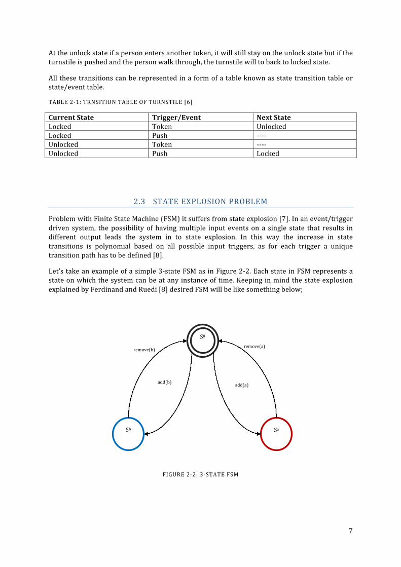
Problem with Finite State Machine (FSM) it suffers from state explosion [7]. In an event/trigger driven system, the possibility of having multiple input events on a single state that results in different output leads the system in to state explosion. In this way the increase in state transitions is polynomial based on all possible input triggers, as for each trigger a unique transition path has to be defined [8].
Let’s take an example of a simple 3-‐state FSM as in Figure 2-‐2. Each state in FSM represents a state on which the system can be at any instance of time. Keeping in mind the state explosion explained by Ferdinand and Ruedi [8] desired FSM will be like something below;
FIGURE 2-‐2: 3-‐STATE FSM
S0
Sa Sb
add(a) add(b)
remove(a) remove(b)

8
TABLE 2-‐2: TRANSITION TABLE FOR 3-‐STATE FSM
S0 is the start state in this FSM, on event add(a) the FSM is now in state Sa. From this point only possibility is remove(a) which will take the machine back to S0. Same case goes for state Sb. Now adding one more state Sab as shown in Figure 2-‐3. Transition from Sab is possible to both Sa and Sb.
FIGURE 2-‐3: 4-‐STATE FSM
TABLE 2-‐3: TRANSITION TABLE FOR 4-‐STATE FSM
Current State Trigger/Event Next State S0 Add(a) Sa S0 Add(b) Sb S0 Remove(a) -‐-‐-‐-‐ S0 Remove(b) -‐-‐-‐-‐
Current State Trigger/Event Next State S0 Add(a) Sa S0 Add(b) Sb S0 Remove(a) -‐-‐-‐-‐ S0 Remove(b) -‐-‐-‐-‐ Sa Add(b) -‐-‐-‐-‐ Sa Add(a) -‐-‐-‐-‐ Sa Remove(b) -‐-‐-‐-‐ Sa Remove(a) S0 Sb Add(a) -‐-‐-‐-‐ Sb Add(b) -‐-‐-‐-‐ Sb Remove(a) -‐-‐-‐-‐ Sb Remove(b) S0
S0
Sa Sb
add(a) add(b)
remove(a)
remove(b)
Sab
add(a) add(b)
remove(a) remove(b)
9
Sa Add(b) Sab Sa Add(a) -‐-‐-‐-‐ Sa Remove(b) -‐-‐-‐-‐ Sa Remove(a) S0 Sb Add(a) Sab Sb Add(b) -‐-‐-‐-‐ Sb Remove(a) -‐-‐-‐-‐ Sb Remove(b) S0 Sab Add(a) -‐-‐-‐-‐ Sab Add(b) -‐-‐-‐-‐ Sab Remove(a) Sb Sab Remove(b) Sa
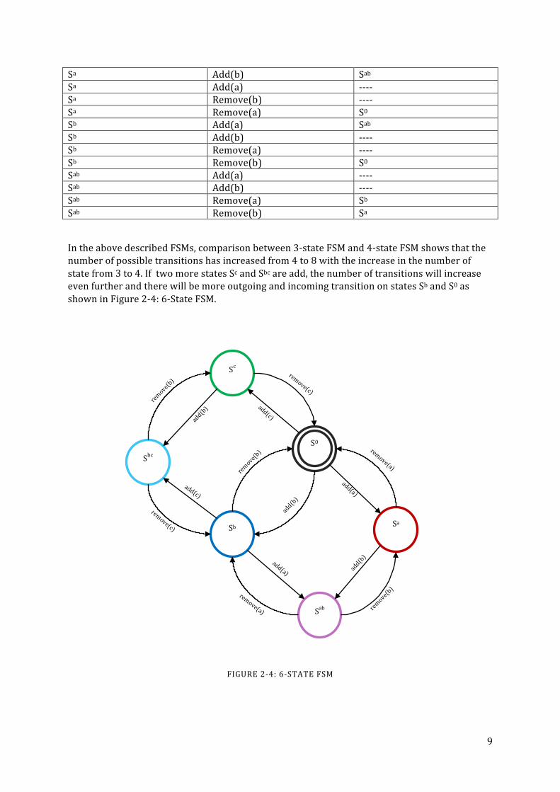
In the above described FSMs, comparison between 3-‐state FSM and 4-‐state FSM shows that the number of possible transitions has increased from 4 to 8 with the increase in the number of state from 3 to 4. If two more states Sc and Sbc are add, the number of transitions will increase even further and there will be more outgoing and incoming transition on states Sb and S0 as shown in Figure 2-‐4: 6-‐State FSM.
FIGURE 2-‐4: 6-‐STATE FSM
S0
Sa Sb
add(a)
add(b)
remove(a) remove(b)
Sab
add(a) add(b)
remove(a) remove(b)
Sc
Sbc
add(c)
remove(b) remove(c)
add(b)
add(c) remove(c)

10
TABLE 2-‐4: TRANSITION TABLE FOR 6-‐STATE FSM1
Current State Trigger/Event Next State S0 Add(a) Sa S0 Add(b) Sb S0 Add(c) Sc Sa Add(b) Sab Sa Remove(a) S0 Sb Add(a) Sab Sb Add(c) Sbc Sb Remove(b) S0 Sc Add(b) Sbc Sc Remove(c) S0 Sab Remove(a) Sb Sab Remove(b) Sa Sbc Remove(b) Sc Sbc Remove(c) Sb
From the above table, it can be observed that increase in number of states increases the number of transition in the system. But there are also other factors like number of events/triggers possible on the state. Each event leads to a new transition, so more event on each state, more possible outgoing transitions.
Similar is the case with the RNC Connection State Handler in which there are more than 100 states and a large number of transitions are possible in between those states. Detailed explanation for the problem is given in Chapter 6.
1 Only valid transitions are shown in this table.

11
3 SOFTWARE TESTING
Software testing is the process to check any software whether it works according to the requirements and while doing so does it show an abnormal behavior. IEEE Standard Glossary of Software Engineering Terminology defines Testing as:
“The process of operating a system or component under specific conditions, observing or recording the results, and making an evaluation of some aspects of the system or components” [9]
This is one of the major fields in Software industry which is indispensable for software development process [3]. Untested software will not only work in an incorrect manner but will also affect customer satisfaction and trust towards the software and its developer.
Software testing is a very vast field and cannot be covered in one chapter, only a brief overview of some aspects like types and levels of testing is explained.
One of the methods of software testing is the boxed methods, and there are three types of boxed methods of testing [9]
1. Black box: It is done solely based on the requirements and specifications of the software, no implementation details are needed.
2. White box: It is based on the internal path structures and how is the software implemented. This compliments the black box testing and required programming skills to implement.
3. Grey box: This is a hybrid type of black box testing in which only we peek in to the box to get the basic understanding of implementation so that effective black box testing can be performed.
Regardless to what every method is selected for testing, there are different levels a software can be tested, most commonly used are [9];
1. Unit: Unit is the smallest possible piece of code in the software that is doing some action. In Java or C++ unit can be class or a function.
2. Integration: Units are integrated together to perform some specific task. Units as individual might be working correctly but when integration is done there might be some faults introduced that are captured on integration level testing.
3. System: System is the highest level of integration in which all the part of software are bundled and are tested on the target hardware. This includes functional tests, usability, availability etc. types of tests.
4. Acceptance: This is similar with the system testing but is done by the customer on the site where the behavior of the software is tested in real environment.
Among all the activities in testing, test case generation is one of the most demanding task and is also the crucial as the testing process is totally dependent on the quality of test cases [10] [11].
12
3.1 MANUAL TESTING
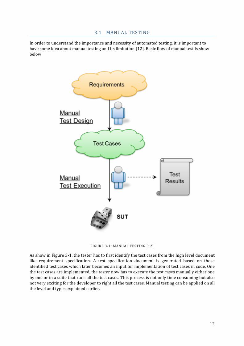
In order to understand the importance and necessity of automated testing, it is important to have some idea about manual testing and its limitation [12]. Basic flow of manual test is show below
FIGURE 3-‐1: MANUAL TESTING [12]
As show in Figure 3-‐1, the tester has to first identify the test cases from the high level document like requirement specification. A test specification document is generated based on those identified test cases which later becomes an input for implementation of test cases in code. One the test cases are implemented, the tester now has to execute the test cases manually either one by one or in a suite that runs all the test cases. This process is not only time consuming but also not very exciting for the developer to right all the test cases. Manual testing can be applied on all the level and types explained earlier.

13
3.2 AUTOMATED TESTING
Types and levels explained before are ways of testing that can be executed both manual and automatic. Best approach is to combine both automated and manual testing to get the best results. This research is related to automated test case generation and execution. It is very important to understand what test automation actually means. As author explains in [13] that the meaning of automated testing is different from person to person depending on their backgrounds and nature of software they are working with. For some it might be Test Driven development TTD for others it might be Data driven Testing DDT or it might be scripted testing.
Test automation has become a key part of software development now a days. It is too expensive to do manual testing as the magnitude of the applications are increasing with a lot of new functionalities. It is hard to keep test coverage and risk reductions to a satisfactory level according to [14].
In simple words, Test automation can be defined as “A software that is designed to test another software.”
In the recent years, a great amount of work has been done in order to generate test cases automatically. Numerous frameworks has been introduced in the market to generate test cases based of different input artifacts such as program source code, software specification and models, input/output data space etc. Although these techniques provide quite good test case generation methods yet there is always a gap between what the software is expected to do and what it actually does. Reason behind this is the increasing complexity of the software by having multi-‐vendor components and running on different platforms [3].
Test automation is a fulltime task not just a sideline job as described by Nagle in [14]. Some useful strategy is also defined in the mention source that help in making automation successful. As the test cases can be generated using different types of input artifacts a few of the techniques has been discussed in this research;
1. Symbolic Execution 2. Model-‐based 3. Data Driven Testing
3.2.1 SYMBOLIC EXECUTION AND TEST CASES GENERATION
According to Saswat and Mary [3], “Symbolic execution is a program analysis technique that analyzes a program‘s code to automatically generate test data for the program.” This is white box testing technique which performs a complete walkthrough of code, explores all the branches. As King mentioned in [15] that symbolic execution uses symbolic values as program inputs and program internal variables are represented as symbolic expressions. A symbolic execution at any point includes;
1. Symbolic values: These are the symbolic expressions that represent the program values. 2. Path Constrains (PC): It is a Boolean formula which applies of the inputs meaning the
inputs must fulfill a certain criteria in order for a specific path to execute. a. True: the path will continue. b. False: path will not continue
3. Program Counter: This holds the pointer to the next statement that needs to be executed.
14
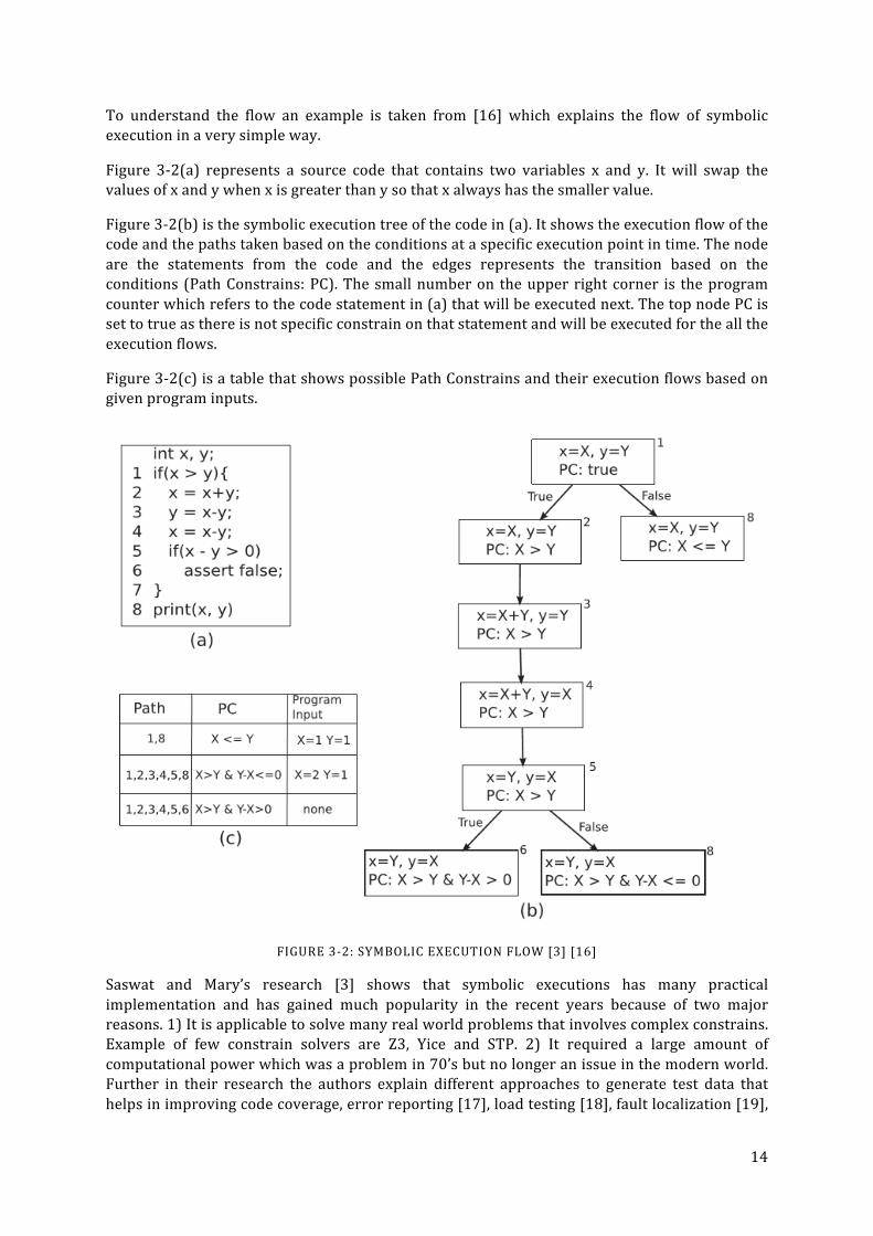
To understand the flow an example is taken from [16] which explains the flow of symbolic execution in a very simple way.
Figure 3-‐2(a) represents a source code that contains two variables x and y. It will swap the values of x and y when x is greater than y so that x always has the smaller value.
Figure 3-‐2(b) is the symbolic execution tree of the code in (a). It shows the execution flow of the code and the paths taken based on the conditions at a specific execution point in time. The node are the statements from the code and the edges represents the transition based on the conditions (Path Constrains: PC). The small number on the upper right corner is the program counter which refers to the code statement in (a) that will be executed next. The top node PC is set to true as there is not specific constrain on that statement and will be executed for the all the execution flows.
Figure 3-‐2(c) is a table that shows possible Path Constrains and their execution flows based on given program inputs.
FIGURE 3-‐2: SYMBOLIC EXECUTION FLOW [3] [16]
Saswat and Mary’s research [3] shows that symbolic executions has many practical implementation and has gained much popularity in the recent years because of two major reasons. 1) It is applicable to solve many real world problems that involves complex constrains. Example of few constrain solvers are Z3, Yice and STP. 2) It required a large amount of computational power which was a problem in 70’s but no longer an issue in the modern world. Further in their research the authors explain different approaches to generate test data that helps in improving code coverage, error reporting [17], load testing [18], fault localization [19],

15
regressing testing [20] and many more. But like all other approaches, symbolic executions suffer from three major issues [3];
1. Path Explosion 2. Path Divergence 3. Complex Constrains
3.2.2 MODEL-‐BASED TESTING
Model-‐based testing (MBT) is a methods to generate test cases from the software model. In this generation method, the insight of the system under test (SUT) is gathered using the formal models and test cases are generated based on the gathered information. According to Wolfgang in [3], there are three approaches which are widely considered for MBT;
1. Axiomatic approach 2. Finite state machine (FSM) approach 3. Labeled transition system (LTS) approach
There are several other approaches which are also being used in the market as explained in [12] a few of them are
• Graphical test modeling approach • Environment model driven approach • System model driven approach
The purpose of all the MBT approaches is the same and that is to generated test cases from the model based documentation [12]. All of these approaches are not discussed in the scope of this research in order to keep it simple.
3.2.2.1 AXIOMATIC APPROACH
According to [3] Axiomatic approach is based on logic calculus. The author referred to existing studies in the domain with the example of a conditional equation.
𝑝 𝑥 → 𝑓1(𝑓2 𝑥 , 𝑐) = 𝑓3(𝑥)
In the above equation f1, f2 and f3 are the internal function of SUT c is a constant p is a predicate x is a variable
The goal here is to find the values of x so that the given equation (SUT) can be tested in detail [21].
3.2.2.2 FSM APPROACH
FSM approach treats the SUT as a state machine where the inputs and outputs are paired up to formulate the transition table and selected transition from the table are executed to test the coverage of the SUT functionality. All this information is extracted from the model of SUT so this approach is prone to failure for incomplete modelled system or system with non-‐deterministic state machine. Once the transition table has been generated from the mode, the tester (system that is testing the SUT) considers the SUT as a black-‐box and injects series of inputs to the SUT and validates the output generated for each input [3].

16
3.2.2.3 LTS APPROACH
According to in [4] Labeled transition system (LTS) consists of following
• Set of states • Set of labels • Transition relation • Initial state • Quiescence (special state)
Where states model the system states and labelled transitions model the actions. The example explained in [4] is about a Candy machine LTS. Figure 3-‐3 represent the LTE of the candy machine where the interaction are but is the button interaction, choc and liq are labels for chocolate and liquor candy respectively. This is the graph representation of transition system with node as states and edges as transition. The states p0, q0, r0, u0, v0 are the start states with arrows coming from nowhere.
FIGURE 3-‐3: CANDY MACHINE LTS [4]
Quiescence is a special state in the system which is applicable in the situation when the SUT is stuck at certain state and no output is generated. This is a special state which is like timeout where the system can be continue the test process without handing. This give LTS an edge so it can work also with non-‐deterministic machines. A set of inputs and expected outputs are specified based on the system model of SUT. A criteria is defined based on which tests are executed on the SUT. As SUT can be non-‐deterministic, some of the output may end up in special quiescence cases but the system is already aware of that.At the end the system checks the union of all the output from SUT with the set of expected outputs generated from model. If the SUT outputs are a sub-‐set of Model output, the test is considered success.
3.2.2.4 TOOLS FOR MBT
There are many MBT tool available in the market both commercial and open source. These tool might use the above mentioned MBT approaches or they can have their own implementations. Wolfgang has mentioned about several tools in his research [3] but here only one will be discussed that is Conformiq Designer.
Conformiq Designer, formally known as QTronic is one of the most popular MBT tool in the market. It has been in the market since 2007 and is widely used in may industrial projects. Conformiq designer has a custom implementation of LTS approach that makes it a very power full tool for test selection procedure [3]. It can design test cases based on Use Case, Requirement coverage, state chart coverage, activity diagram, control flow, statement coverage, all-‐path

17
coverage and more [22]. In can design test cases for various programming languages, TTCN-‐3 (The Testing and Test Control Notation Version 3) and manual test instructions [3]
3.2.3 DATA DRIVEN TESTING
Data Driven Testing (DDT) or Keyword driven testing is one of the most commonly used automation technique as it is simple to implement and execute. But the overhead associated with it is maintainability which is the difficult task [14].
FIGURE 3-‐4: DDT EXECUTION FLOW
As in Figure 3-‐4 DDT is based on some input data which triggers the code and generates the required output. Input data can be an excel file with table of values or can be a simple text file with input keywords. The tested system takes the input, performs the desired action and compares the actual output with expected output to decide pass and failure cases. As the test data is stored in files the scripts running the test can be reused with multiple SUTs and different test data files [12].
All the above mentioned techniques of automation can be using individually or they can be combined with each other in order to suit the requirements. In this research more focus is on DDT combined with FSM approach of model-‐based testing.
Input Action Expected Output
Take Input and perform Action
Actual Output
Actual vs. Expected
Result : pass/fail

18
4 UMTS OVERVIEW
UMTS stands for Universal Mobile Telecommunication System that is the 3rd generation of mobile communication system which is originally based on 2G (GSM) system. [23] UMTS uses Wideband Code Division Multiple Access (WCDMA) whereas GSM uses Time Division Multiple Access (TDMA) radio scheme. WCDMA is spectral efficient both in term of performance and capacity than TDMA. In WCDMA each user is assigned a specific code while transmitting and receiving data over the air interface.
4.1 UMTS ARCHITECTURE
UMTS architecture is based on three major components.
1. User Equipment (UE) 2. Access Network (AN/UTRAN) 3. Core Network (CN)
FIGURE 4-‐1: UMTS OVERVIEW
User Equipment (UE)
The device or Equipment that is used to access the network is called User Equipment (UE). UE can be any device that needs to access to network to get desired service. Services include internet connection, voice call or both. UE is consist of two logical parts
19
1. Universal Subscriber Identity Module (USIM): It is a module that contains a unique identifier for the UE so the network can easily identify the User bases on it. This is called International Mobile Subscriber's Identity (IMSI).
2. Mobile Equipment (ME): ME is the hardware manufactured by the mobile manufacturing company like Samsung, Apple or Nokia etc. which provides interface to use the networks services besides other functionalities.
Access Network (AN or UTRAN)
Access network (AN) is a bridge that allows the UE to connect to the CN and access the services. In UMTS the AN is called Universal Terrestrial Radio Access Network (UTRAN) as shown in Figure 4-‐1. UTRAN consists of set of NodeBs and RNCs, NodeBs are connected with the RNC using Iub2 interface whereas two RNCs are connected with each other using Iur3 interface.
Core Netwrok
Core Network (CN) is another network element in the system that can be connected to all types of ANs 2G, 3G and 4G. The purpose of the CN is to provide speech or data services to the UE using the AN. CN is connected to AN using Iu-‐PS or Iu-‐CS4 depending on the type of CN. The Iu interface ends up at RNC in the AN.
4.2 RAB AND RAB COMBINATIONS (UERCS)
4.2.1 RADIO ACCESS BEARER (RAB)
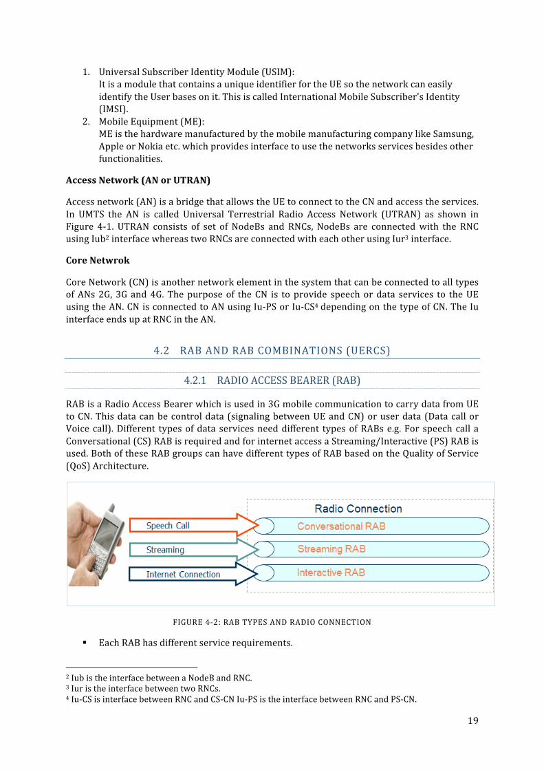
RAB is a Radio Access Bearer which is used in 3G mobile communication to carry data from UE to CN. This data can be control data (signaling between UE and CN) or user data (Data call or Voice call). Different types of data services need different types of RABs e.g. For speech call a Conversational (CS) RAB is required and for internet access a Streaming/Interactive (PS) RAB is used. Both of these RAB groups can have different types of RAB based on the Quality of Service (QoS) Architecture.
FIGURE 4-‐2: RAB TYPES AND RADIO CONNECTION
§ Each RAB has different service requirements.
2 Iub is the interface between a NodeB and RNC. 3 Iur is the interface between two RNCs. 4 Iu-‐CS is interface between RNC and CS-‐CN Iu-‐PS is the interface between RNC and PS-‐CN.

20
§ Some with Guaranteed bit rate (GBR) and some with non GBR.
§ Low delay for conversational.
§ Efficient usage of radio resources for interactive.
§ Different priority for each RAB.
According to 3GPP QoS standards, UMTS Bearer consists of RAB and CN Bearer, the RAB itself is based on Radio Bearer (RB) and Iu-‐Bearer [24]
TE MT UTRAN CN IuEDGENODE
CNGateway
TE
UMTS
End-to-End Service
TE/MT LocalBearer Service
UMTS Bearer Service External BearerService
UMTS Bearer Service
Radio Access Bearer Service CN BearerService
BackboneBearer Service
Iu BearerService
Radio BearerService
UTRAFDD/TDD
Service
PhysicalBearer Service
FIGURE 4-‐3: UMTS QOS ARCHITECTURE [24]
Each RAB consists of a number of attributes like;
1. Traffic Class 2. Maximum bit rate 3. Guaranteed bit rate 4. Transfer Delay etc.
In this research only two of the above attributes will be used Traffic Class, Maximum bit rate. These two parameters are sufficient enough to make the decision which RAB class is required by the user. The remaining parameters are used by the network system to control the traffic.
21
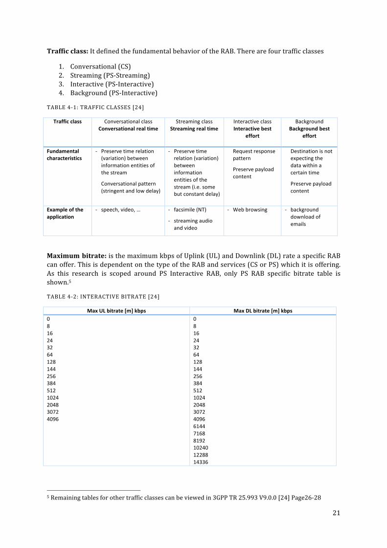
Traffic class: It defined the fundamental behavior of the RAB. There are four traffic classes
1. Conversational (CS) 2. Streaming (PS-‐Streaming) 3. Interactive (PS-‐Interactive) 4. Background (PS-‐Interactive)
TABLE 4-‐1: TRAFFIC CLASSES [24]
Traffic class Conversational class Conversational real time
Streaming class Streaming real time
Interactive class Interactive best
effort
Background Background best
effort
Fundamental characteristics
-‐ Preserve time relation (variation) between information entities of the stream
Conversational pattern (stringent and low delay)
-‐ Preserve time relation (variation) between information entities of the stream (i.e. some but constant delay)
Request response pattern
Preserve payload content
Destination is not expecting the data within a certain time
Preserve payload content
Example of the application
-‐ speech, video, … -‐ facsimile (NT)
-‐ streaming audio and video
-‐ Web browsing -‐ background download of emails
Maximum bitrate: is the maximum kbps of Uplink (UL) and Downlink (DL) rate a specific RAB can offer. This is dependent on the type of the RAB and services (CS or PS) which it is offering. As this research is scoped around PS Interactive RAB, only PS RAB specific bitrate table is shown.5
TABLE 4-‐2: INTERACTIVE BITRATE [24]
Max UL bitrate [m] kbps Max DL bitrate [m] kbps 0 8 16 24 32 64 128 144 256 384 512 1024 2048 3072 4096
0 8 16 24 32 64 128 144 256 384 512 1024 2048 3072 4096 6144 7168 8192 10240 12288 14336
5 Remaining tables for other traffic classes can be viewed in 3GPP TR 25.993 V9.0.0 [24] Page26-‐28

22
4.2.2 RAB COMBINATIONS (UERCS)
Any number of the above mentions RABs can be combined to formulate RAB combinations. Depending on each RAB or RAB combination selected for a connection, the RNC configures the required parameters and selects appropriate RBs [24]. In this research, RAB combinations are represented as UeRcs (User Equipment Radio Connection) thus each RAB Combination or UeRc represent a unique state. Some example UeRcs in Table 4-‐3.
UeRc:0 #[Idle]
UeRc:2 #[Conversational CS Speech (12.2/12.2)] UeRc:5 #[Interactive PS (64/64)] UeRc:6 #[Interactive PS (64/128)]
UeRc:10 #[Conversational CS Speech (12.2/12.2) + Interactive PS (64/64)]
UeRc:15 #[Interactive PS (64/HS)] UeRc:19 #[Conversational CS Speech (12.2/12.2) + Interactive PS (64/HS)]
UeRc:21 #[Interactive PS (URA/URA)]
UeRc:25 #[Interactive PS (EUL/HS)]
UeRc:26 #[Interactive PS (64/64) + Interactive PS (64/64)]
UeRc:27 #[Conversational CS Speech (12.2/12.2) + Interactive PS (64/64) + Interactive PS (64/64)]
UeRc:54 #[Interactive PS (64/HS) + Interactive PS (64/HS)]
UeRc:123 #[Conversational CS Speech (12.2/12.2) + Interactive PS (EUL/HS)]
UeRc:124 #[Conversational CS Speech (12.2/12.2) + Interactive PS (EUL/HS) + Interactive PS (EUL/HS)]
UeRc:125 #[Conversational CS Speech (12.2/12.2) + Interactive PS (EUL/HS) + Interactive PS (EUL/HS) + Interactive PS (EUL/HS)] UeRc:128 #[Interactive PS (EUL/HS) + Interactive PS (EUL/HS) + Interactive PS (EUL/HS)]
TABLE 4-‐3: UERC LIST
Each UeRc state has a state number and it consists of one or more RABs. For example UeRc:6 has one PS interactive RAB with 64Kbps Uplink and 128Kbps Downlink speed. Above mentioned states are just a subset of UeRc States those exist in the system6. These states will be the input to the test system that will generate a possible transition table based on the different RABs in each state.
6 Complete List of UeRcs can be viewed in Appendix A-‐2

23
5 METHODOLOGY
To find the solution to the problem, simple software analysis, design and evaluation methodologies are used.
5.1 ANALYSIS
First step is the analysis, a detailed study of the RNC Connection State Handler is conducted to identify the key problems and following observations were made;
1. What the system is actually doing? 2. How complex is the system? 3. What is already being tested and how? 4. What is not tested and why?
The analysis of the RNC Connection State handler is done using the following sources as input:
1. 3GPP specification for RAB Combinations [24]. 2. System documentation of the implemented system. 3. Code walkthrough. 4. Discussion with system engineers who were experts in the area.
Reading the 3GPP specification for RAB combination helped in understanding what are RABs and RAB combinations and how they should be implemented in order to provide voice or data services. This provided information of what to expect from the system and what to test.
System documentation and code walkthrough were done in order to understand the RNC connection state handler implementation. The system from the production perspective is implemented in a sophisticated way so that it fulfills the requirements of 3GPP specification. From test perspective however, it was not so flexible when in come to add or remove RAB combinations. Details about the actual system are not in the scope of this research and will not be covered here. Some explanation about the behavior of SUT is explained with the explanation of simulator in chapter 7.2.1
5.2 DESIGN
Based on the outcome of the system analysis, the problem is then broken down into two parts for simplified handling.
1. Transition Table Generator 2. Test Executor
o Executor o Simulator
Based on the connection states existing in the system, the first thing targeted was to generate a transition table for the states that exist. For this the input used was connection states (RAB combinations according to 3GPP) that has been implementation within the SUT. A program was then sketched in order to parse the input states and generate a transition table. The states where represented as logical sets. Each state can contain a number of RABs. This sketch was later implemented as Java program which is independent of the actual SUT itself. Only a subset of states have been considered to minimize the scope and complexity of this research.
24
Once the transition table generator was in place, came the next phase of using the generated table. The goal here was to take the transition table and feed it to the SUT in a way that all the transition in the transition table are executed and then validated. To make this possible, Executor was designed which is written in C++. To verify the behavior and execution of the executor on the real system was a challenge. The real system can only be run under Ericsson specific environment. So the decision was made to implement a Simulator that will behave like a stub and will give limited but similar output as the original SUT. Implementation details for both executor and simulator are provided in chapter 7.2.
5.3 EVALUATION
For any decision a company makes, there is always a cost benefit analysis (CBA) performed. Similarly is the case with this study is to see if implementing such an improvement will ultimately provide any benefit or not. In this study a multi objective multi criteria (MOMC) method has been chosen for qualitative evaluation. Following three criteria are considered;
1. Output validity. 2. Implementation complexity. 3. Maintenance overhead.
Output based evaluation is done on the output generated by the developed script compared to the excepted outcomes that has been manually calculated by the system engineer based on the inputs. For this evaluation a small subset of inputs were taken to generate the respective output. Similar subset of inputs where given to the system engineer to calculate the desired outputs. Then a comparison is done between the outputs provided by the system engineer and the script generated outputs. There is no other way to do evaluation as this is how the previous test cases were updated, a system engineer used to write down possible important transitions from the newly added states and those where many added in the SUT to execute.
Second evaluation done is based on implementation complexity. This is to check how complex and difficult it is to implement the proposed solution in the actual test environment. For this decoupling of the proposed solution with the SUT and test framework was evaluated.
Third evaluation is related to maintainability of the scripts and executor code. This is done by guessing what types of changing or updates can occur in the system and how will they effect the proposed solution. As proposed by the authors in [25] there are many metrics to calculate the maintenance efforts. Few of them are Maintainability Index (MI), Structure Measurements (SM) and Code Smells
In this study we use Maintainability Index as a metric just to show some measurement effort. To make work easy a 3rd party tool JHawk5 is used to measure the MI. However there are several issue with the MI explained in [26] and the authors also suggest a maintenance model they have proposed. The model uses five difference metrics Volume, Complexity per unit, Duplication, Unit size and Unit testing. We will also consider volume i.e. line of code (LOC) metric.
25
6 PROBLEM DESCRIPTION
The problem under consideration is a well-‐known issue in state machines where there are a large number of states and the number of transitions in between them grow polynomial. This makes the system very huge and difficult to test all possible combinations.
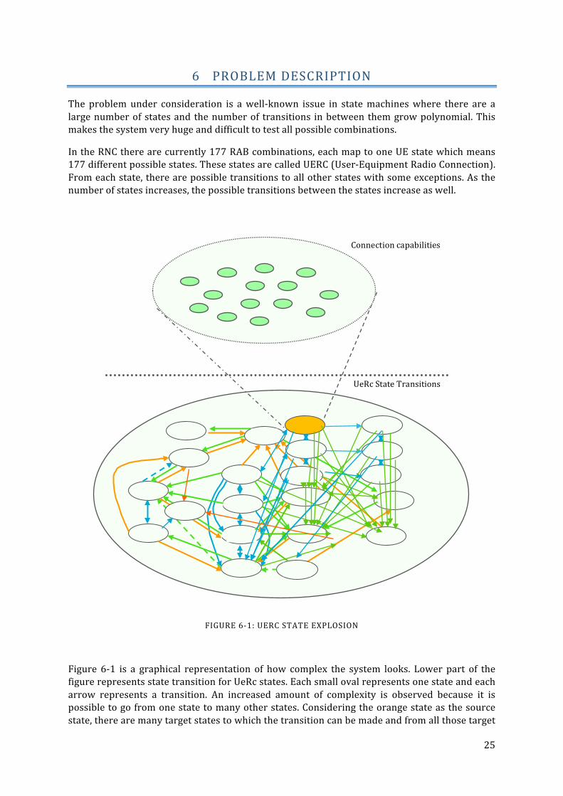
In the RNC there are currently 177 RAB combinations, each map to one UE state which means 177 different possible states. These states are called UERC (User-‐Equipment Radio Connection). From each state, there are possible transitions to all other states with some exceptions. As the number of states increases, the possible transitions between the states increase as well.
FIGURE 6-‐1: UERC STATE EXPLOSION
Figure 6-‐1 is a graphical representation of how complex the system looks. Lower part of the figure represents state transition for UeRc states. Each small oval represents one state and each arrow represents a transition. An increased amount of complexity is observed because it is possible to go from one state to many other states. Considering the orange state as the source state, there are many target states to which the transition can be made and from all those target
Connection capabilities
UeRc State Transitions
26
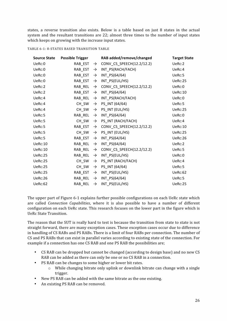
states, a reverse transition also exists. Below is a table based on just 8 states in the actual system and the resultant transitions are 22; almost three times to the number of input states which keeps on growing with the increase input states.
TABLE 6-‐1: 8-‐STATES BASED TRANSITION TABLE
Source State Possible Trigger
RAB added/remove/changed Target State UeRc:0 RAB_EST → CONV_CS_SPEECH(12.2/12.2) UeRc:2 UeRc:0 RAB_EST → INT_PS(RACH/FACH) UeRc:4 UeRc:0 RAB_EST → INT_PS(64/64) UeRc:5 UeRc:0 RAB_EST → INT_PS(EUL/HS) UeRc:25 UeRc:2 RAB_REL → CONV_CS_SPEECH(12.2/12.2) UeRc:0 UeRc:2 RAB_EST → INT_PS(64/64) UeRc:10 UeRc:4 RAB_REL → INT_PS(RACH/FACH) UeRc:0 UeRc:4 CH_SW → PS_INT (64/64) UeRc:5 UeRc:4 CH_SW → PS_INT (EUL/HS) UeRc:25 UeRc:5 RAB_REL → INT_PS(64/64) UeRc:0 UeRc:5 CH_SW → PS_INT (RACH/FACH) UeRc:4 UeRc:5 RAB_EST → CONV_CS_SPEECH(12.2/12.2) UeRc:10 UeRc:5 CH_SW → PS_INT (EUL/HS) UeRc:25 UeRc:5 RAB_EST → INT_PS(64/64) UeRc:26 UeRc:10 RAB_REL → INT_PS(64/64) UeRc:2 UeRc:10 RAB_REL → CONV_CS_SPEECH(12.2/12.2) UeRc:5 UeRc:25 RAB_REL → INT_PS(EUL/HS) UeRc:0 UeRc:25 CH_SW → PS_INT (RACH/FACH) UeRc:4 UeRc:25 CH_SW → PS_INT (64/64) UeRc:5 UeRc:25 RAB_EST → INT_PS(EUL/HS) UeRc:62 UeRc:26 RAB_REL → INT_PS(64/64) UeRc:5 UeRc:62 RAB_REL → INT_PS(EUL/HS) UeRc:25
The upper part of Figure 6-‐1 explains further possible configurations on each UeRc state which are called Connection Capabilities, where it is also possible to have a number of different configuration on each UeRc state. This research focuses on the lower part in the figure which is UeRc State Transition.
The reason that the SUT is really hard to test is because the transition from state to state is not straight forward, there are many exception cases. These exception cases occur due to difference in handling of CS RABs and PS RABs. There is a limit of four RABs per connection. The number of CS and PS RABs that can exist in parallel varies according to existing state of the connection. For example if a connection has one CS RAB and one PS RAB the possibilities are;
• CS RAB can be dropped but cannot be changed (according to design base) and no new CS RAB can be added as there can only be one or no CS RAB in a connection.
• PS RAB can be changes to some higher or lower bit rates. o While changing bitrate only uplink or downlink bitrate can change with a single
trigger. • New PS RAB can be added with the same bitrate as the one existing. • An existing PS RAB can be removed.

27
Keeping in mind that there are different kinds of CS and PS RABs, the above mentioned rules apply to all of them which makes the testing more difficult. It depends on the input trigger at a given state that what will be the next state. But there are some cases in which not all the triggers are applicable.
Triggers are the condition which invoke the state transition. There are 3 types of triggers,
1. RAB Establish -‐ Adding a new RAB to current connection. 2. RAB Release -‐ Removing existing RAB from current connection. 3. Channel Switching -‐ Changing data rate of existing PS RAB(s)
RAB Establish trigger comes with the RAB that need to be added to the current connection. It can be a CS or PS RAB, but will be based on the current connection states as if there is already existing CS RAB there can’t be a RAB Establish trigger with CS RAB indicator. A PS RAB however can be added based on following conditions.
1. If there is not PS RAB already existing then add the PS RAB 2. If there exist a PS RAB already in the connection only add if the PS RAB indicated in the
RAB Establish triggers matches the existing one.
RAB Release trigger is simple as the trigger comes with the RAB that needs to be removed. If the CS or PS RAB mentioned in the trigger exists, the specific RAB will be removed from the connection.
Channel switching trigger can only occur for PS RABs as no rate changing support of CS RABs. This trigger contains two type of RAB information, the affected RAB ID and the new rates.
Each transition has guard conditions, these conditions are based on the input trigger, and the resultant action depends the number of RABs in that state and data rate of each RAB that will be affected by the trigger. These are described earlier as exception cases.
In the RNC Connection State Handler, there is a test framework that is performing some basic tests. The problem with it is that the input transition has to be provided manually. So the designer or tester has to manually write down which transition that needs to be tested. The test framework then executes the desired transitions. At the end it just reports if the transition passed or failed. Adding to the problem is that if the tester wants to test 10 new transitions and the transition number 6 fails for some reason, the framework will skip the remaining and will report failure. The problem with this approach is even if the failed test case is fixed, it is not certain that all the remaining test cases will pass. If one of them fails, then same correction process is repeated until all the test cases pass.
Another drawback with the existing testing approach is only certain states and transitions are tested. This leads the system prone to errors which can cause serious problems and can be really difficult to troubleshoot. Exploratory testing is too expensive if done manually. Automating it can provide a stable solution to the problem.
In addition to the complexity of the system is the connection capabilities on each state. It is possible that the connection is on the same states (same RAB combination) but then with different connection capabilities. To keep it simple based on limited time and resources for this research connection capability handling will not be included.

28
7 SOLUTION SKETCH AND IMPLEMENTATION
In this research, SUT is RNC connection state handler is a sub-‐system of RNC. This sub-‐system handles all the activities related to UEs. i.e. connection establishment, connection release and mobility etc. It also keeps track of all RAB states for each user and handles state changes centrally in a generic way. This makes the system very flexible when new states are added or existing states are removed. Test suites for this sub-‐system however are not as generic, where addition and removal of states have to be updated manually.
FIGURE 7-‐1: SOLUTION BREAKDOWN

29
The core focus of this research is to find a solution that automatically determine and validate new transitions upon addition of new states. The problem as described in the previous chapter is whenever a new state is added to the system, the incoming and outgoing transitions should be manually added in the transition table and then specific test cases should be written. This is not only time consuming but also a hectic task for the developer just to test as many transitions as possible.
In this research, a Java based program to automate test case generation is used. The solution consists of two steps;
1. Extracting information from the RAB combination table using a script and generating a state transition table from it.
2. Automatic test case execution from the state transition table.
7.1 DATA EXTRACTION AND TRANSITION TABLE GENERATION
In the first step the input file containing the UeRc states is parsed. This is a plain text file which contains all the states that are used in the system. The parsed information is then handled using String Class in Java that provides a vast majority of string operations and container that will help in filtering the data. The input file data looks as follow;
UeRc:5 #[Interact. PS (64/64) + SRB(3.4/3.4)]
UeRc:10 #[Conv. CS speech (12.2/12.2) + Interact PS (64/64) + SRB (3.4/3.4)]
UeRc:15 #[Interact. PS (64/HS) + SRB(3.4/3.4)]
UeRc:25 #[Interact. PS (EUL/HS) + SRB(EUL/3.4)]
TABLE 7-‐1: INITIAL INPUT DATA
Table 7-‐1 shows information is extracted from the RAB state definition class where for each UeRc there is a lot of information and definition part but also a plain text (as above) which is always in this format. It explains what the UeRc consists of. e.g. for state UeRc:10 we can see it is a multi-‐RAB state. First RAB is Conversational CS Speech with 12.2 Kbps uplink and 12.2 Kbps downlink speed. The second RAB is an Interactive PS Packet 64 Kbps uplink and 64 Kbps downlink speed. This information is extracted and stored in a separate file which is used as an input file. SRB is the Signaling Radio Bearer which is used for control signal between RNC and UE. This has been removed during the extraction of data as it is basic part for all the states and will always be there by default. Final input data is as shown in Table 7-‐2.
UeRc:5 #[Interact. PS (64/64)]
UeRc:10 #[Conv. CS speech (12.2/12.2) + Interact PS (64/64)]
UeRc:15 #[Interact. PS (64/HS)]
UeRc:25 #[Interact. PS (EUL/HS)]
TABLE 7-‐2: ACTUAL INPUT DATA (NO SRB)
To handle the problem in a more mathematical approach, each state is represented as a Set which consists of zero to more RAB elements. Let's take a few examples

30
EXAMPLE OF STATE SETS.
Representing the states in the form of sets makes it easy to find relationships between states and it gets simpler to apply different conditions to compare the states. This helps to identify if the transition from a state to another state is possible and if so what would be the trigger.
For Example
From the above example we can see transition from A (UeRc:10) to B (UeRc:2) is possible with the Establishment Trigger for r2 (Interact. PS [64/64]).
Dividing the problem in two different groups those lead to state changing,
1. Establish and Release In this cases either a new RAB is established or an existing RAB is removed. So the number of RABs in source and target states will always be different.
2. Channel Switching UL/DL Rates of any exiting RAB is changed. So the number of RAB(s) are same in source and target states.
UeRc:0 = {}
where: {} is empty set also denoted as Ø
UeRc:10 = {r1,r2}
where: r1 = Conv. CS speech (12.2/12.2) r2 = Interact. PS (64/64)
UeRc:2 = {r1}
where: r1 = Conv. CS speech (12.2/12.2)
A = UeRc:10 = {r1,r2} B = UeRc:2 = {r1} where |A| = 2 and |B| = 1 therefore A/B = {r2}
So B->A transition is possible with addition of r2 B + {r2} = A

31
7.1.1 ESTABLISHMENT AND RELEASE GROUP
Establishment and release group contains all the state transitions which are triggered based on RAB Establishment or RAB Release.
Establish and Release triggers are applicable where there is a difference in number of RABs between the source and target states. The difference should be of one. e.g.
No.of RABs in UeRc:0 = n0 = 0 No.of RABs in UeRc:2 = n2 = 1 (CS) No.of RABs in UeRc:5 = n5 = 1 (PS) No.of RABs in UeRc:10 = n10 = 2 (CS + PS)
As illustrated in Figure 7-‐2 Transition from UeRc:0 to UeRc:2 and UeRc:5 is possible and vice versa as difference of no.of RABs is 1 whereas no transition is possible in between UeRc:2 and UeRc:5.
n2 - n0 = 1 n5 - n0 = 1 n2 - n5 = 0 (transition not possible)
Similarly from UeRc:2 and UeRc:5 to UeRc:10 the transition is possible and vice versa. Whereas transition in between UeRc:0 to UeRc:10 is not possible (in one step)
n10 - n2 = 1 n10 - n5 = 1 n10 - n0 = 2 (transition possible in two step)
In UeRc:10 to UeRc:0 case, the transition is still possible but in two step which will not be considered here as the two single step transitions will be covered by two individual transitions.
The rule to find transition between states where RAB Establish and RAB release triggers are applicable is as follow:
UeRc:2 #RAB = 1
UeRc:10 #RAB = 2
UeRc:5 #RAB = 1
UeRc:0 #RAB = 0
RE: CS(12.2/12.2)
RE: PS(64/64)
RR: CS(12.2/12.2)
RR: PS(64/64)
RE: PS(64/64)
RR: PS(64/64)
RE: CS(12.2/12.2)
RR: CS(12.2/12.2)
FIGURE 7-‐2: ESTABLISH AND RELEASE STATE MACHINE

32
Algorithm that will handle establishment and release cases (Algorithm 1):
ALGORITHM 1: ESTABLISH AND RELEASE
This Group handles all the transition where Source and Target States has different number of RAB and both source and target states has similar RABs except one. This also covers all the transition From and To Idle State (UeRc:0)
7.1.2 CHANNEL SWITCHING GROUP
This group handles transitions based on channel switching which means changing an existing RAB. Channel Switching is possible only if the Source and Target states have same number of RAB provided that one of the RAB not common in both. There are some additional conditions on the uncommon RAB in order to trigger channel switching.
Special RAB diff Criteria (RDC) that should be fulfilled by the uncommon RABs;
A = {r1, r2} |A| = 2 B = {r1} |B| = 1
So:
B ⊂ A (B is the sub-set of A) |A| - |B| = 1 (mean Rab Establish and Release Trigger possible)
Therefore: A / B = {r2}
So B ⇾ A transition is possible with RAB Establish {r2} B + {r2} = A and A ⇾ B transition is possible with Release {r2} A/{r2} = B
Loop-1 For each state A in states
nA = no. of Rabs in A state
Loop-2 For each state B in states
nB = no.of Rabs in B state if nB equals nA +1 AND B.subset(A) = true
r’ = diff(B, A) update transition table with A ⇾ B; Establish; r’ B ⇾ A; Release; r’
end if
end Loop-2
end Loop-1

33
1. Change should be in either uplink or downlink rate at a time. 2. The rate change should be only one step up or down.
e.g. PS(64/64) to PS(64/128) 3. Channel switch to and from any PS RAB to PS RACH/FACH is possible. 4. Channel switch to and from any PS RAB to PS EUL/HS is possible. 5. Channel switch to and from any single PS RAB state to URA/URA is possible.
The rule to find Channel Switching transition between two states can be explained as;
Algorithm that will handle channel switching cases (Algorithm 2):
A = {r1, r2, r3} |A| = 3 B = {r1, r2, r4} |B| = 3
So:
A ∩ B = B ∩ A = {r1, r2} B / A = {r4} A / B = {r3} |A| - |B| = 0
Note: r3 and r4 should fulfil the criteria mention above.
Therefore: A ⇾ B = (A ∩ B) ∪ (B / A) B ⇾ A = (A ∩ B) ∪ (A / B)
UeRc:6 #RAB = 1
UeRc:7 #RAB = 1
UeRc:5 #RAB = 1
CSW: PS(64/64) PS(64/128)
UeRc:25 #RAB = 1
CSW: PS(64/128) PS(64/64)
CSW: PS(64/128) PS(EUL/HS)
CSW: PS(EUL/HS) PS(64/128)
CSW: PS(64/64) PS(EUL/HS)
CSW: PS(EUL/HS) PS(64/64)
CSW: PS(64/128) PS(64/384)
CSW: PS(EUL/HS) PS(64/384)
CSW: PS(64/384) PS(EUL/HS)
CSW: PS(64/384) PS(64/128)
FIGURE 7-‐3: CHANNEL SWITCING STATE MACHINE

34
ALGORITHM 2: CHANNEL SWITCH
7.1.3 IMPLEMENTATION OF TRANSITION TABLE GENERATOR
Transition table generator is implemented in Java, The code is divided into two main classes, First class named as StateNamesAndRabs (see AppendixAppendix -‐ A3-‐a) takes in the input file, it parses the file and store the file UeRc names along with RAB names and RAB Rates in ArrayList of String type. This is a simple class and just behaves as a container for the data which makes it easy to parse the data. This class contains two data members;
nameOfState(ArrayList of String): which store the name for each state like UeRc:5, UeRc :10 etc.
stateRabs(ArrayList of ArrayList of String): contains RABs for each state e.g. for UeRc:5 RAB is Single-‐RAB which is Interactive PS (64/64) whereas UeRc:10 is a Multi-‐RAB so it will store both Conversational CS Speech 7(12.2/12.2) Interactive PS (64/64)7.
Once the extracted data is stored in the container class, now comes the complicated part to generate the transition table from stored data. This action is done by the second class TransitionAnalysis in Java code (see Appendix Appendix -‐ A3-‐b). The parsing of transitions are done in steps;
First task is to handle all the transition from Idle state (UeRc:0) to all other states with single-‐RAB UeRc using Algorithm 1. It always possible from Idle state to establish a new RAB. Also handle reverse transition from all the single-‐RAB UeRc to Idle state as it is always possible to release the existing RAB and go to Idle state. The main function is listOfTransitions which handles the basic flow. This flow is quite simple it is only to loop through UeRc list and for each UeRc which has single-‐RAB there is a to and from transition to Idle State (UeRc:0). This case is executed and handles within listOfTransitions method.
7 The SRB part of the UeRc is ignored in this case as it does not really matters for the current scope and is not really involved in state changing.
Loop-1 For each state A in states
nA = no. of Rabs in A state
Loop-2 For each state B in states
nB = no.of Rabs in B state if nB equals nA r’ = diff(A, B) r” = diff(B, A) if r’ and r” passes criteria RDC A ⇾ B; Channel Switch; r’ to r” B ⇾ A; Channel Switch; r” to r’
end if
end if
end Loop-2
end Loop-1
where RDC = RAB Diff criteria mentioned at the start of 7.1.2

35
Continuation to this is handling Establish and Release triggers which also done by using Algorithm 1. Logic is same as mentioned in the algorithm, loop through all the states and check the condition of RAB difference equals to one. If this is true it is possible to have RAB Establishment to go from lower state to higher state and vice versa. States which pass the first criteria are passed on to the method findPossibleTransitions which filters out if the transition is possible within the two states. If filter comes with a positive result, the transition is added to the transition table.
Then comes the Channel Switching part which is handled using Algorithm 2. As defined by the algorithm, channel switching can only be done if the number of RABs are equal on both states. Also it only possible for PS RABs. A call to checkIfTransitionIsPossible is given in order to identify the RAB difference criteria fulfills and the transition is logged into the transition table.
The output generated by this script is a text file which contains the source states, target states, input trigger and the effected RAB, all of these printed separated by semi colon “;”.
TABLE 7-‐3: OUTPUT FORMAT OF SCRIPT
UeRc:0;UeRc:2;RAB_EST;CONV_CS_SPEECH(12.2/12.2) UeRc:2;UeRc:0;RAB_REL;CONV_CS_SPEECH(12.2/12.2) UeRc:5;UeRc:6;CW_SW;PS_INT (64/128) UeRc:5;UeRc:10;RAB_EST;CONV_CS_SPEECH(12.2/12.2) UeRc:10;UeRc:5;RAB_REL;CONV_CS_SPEECH(12.2/12.2) UeRc:25;UeRc:5;CW_SW;PS_INT (64/64)

36
7.2 AUTOMATED TEST CASE EXECUTOR
The Transition table generator program has performed its part and has generated the transition table as per requirement. The next step is to use that as input for the testing system. As mentioned in the problem description in Chapter 6, there already exists a test environment in SUT but the transitions have to be added manually to the system in order to run the test. Based on the static state transition input, the test environment is designed in a way to call the specific sets of functions that will execute the state transition. The test environment is capable of running the tests if it is told which transition to perform. But it has its limitations as the input is manual.
The original code source cannot be used in this study as is because of two major reasons.
1. It is complicated and cannot be executed outside company’s environment. 2. It is Ericsson proprietary code that can note be published.
To overcome the above obstacles, a state transition simulator has been written in C++ so that the transition table generated by the Java based script could be tested. This simulator along with the test executor that reads the transition table and triggers the test cases. In this way the test cases are automatically executed and verified.
The C++ project RabStateHandler consists of two parts
1. Simulator, which behaves as the Ericsson RAB handler change states based on triggers. 2. Executor, which executes the test cases by parsing the input transition table file and
triggering each state transition in the Simulator.
7.2.1 SIMULATOR
Simulator consists of the classes and functions that allow the program to behave as Ericsson’s Connection state handling logic which is the SUT. What happens in the actual SUT is the UE is connected to the system in any state. At this a trigger is generated that requires the change in current state. The triggers can be generated for following reasons;
1. UE related: a. Requesting a new service. b. Terminating an existing service.
2. RNC related: a. Changing the service based on amount of data being transmitted or received. b. Dropping the service due to inactivity.
3. CN related: a. Incoming service request for a specific UE (receiving an incoming call). b. Services being terminated from the remote side (call ended from remote side).
All the above generated triggers are handled by RNC’s Connection state handler. Once the trigger is received, the SUT makes the evaluation or the trigger in correspondence to the type of UE and its capabilities. It also checks capacity of the current system based on system load and several other factors. Once all internal checks are passed, a decision is made to process the trigger and change the state of the connection. The new state must correspond to the UeRc reference states supported by the system (See Appendix A-‐2). The important checks on which this research focuses are;

37
• Generated input trigger (Transition table generator). • Performing the transition based on trigger (Simulator). • Validating generated output (Executor).
The purpose of the simulator is to function as the RAB state handler but avoid all the complex logic involved in the actual system. The actual RAB state handler is very complex and is tightly coupled with other software components of RNC which makes it almost impossible to isolate the code for this research. For this reason the simulator is created which just behaves as a stub. The simulator is controlled by the executor (explained later 7.2.2) which reads the transition table generated by the Transition table generator (explained earlier 7.1) and feeds it to the simulator. The simulator contains a UeRcState class which represents the current state of a connection. On receiving the trigger and RAB parameters from executor, the simulator adds, removes or changes a RAB and transits to a new state which conforms the UeRc state reference (Appendix A-‐2). If the trigger or the RAB parameters are incorrect, simulator will go to an invalid state. Which will indicate that the requested transition is invalid. The UeRc state reference file is a part of the simulator and a set of support functions in the common library ensure that the new state is correct or not. When the simulator is replaced by the actually RAB state handler, these check are removed from the executor as those are done by the system itself. If system establishes a wrong state this will indicate a fault in the system and test framework will catch it.
The simulator section has the following code components: (+ public and -‐ private)
Class Rab: contains the basic properties of a RAB, which includes
• Parameters o -‐ _type:rabType o -‐ _ul:ulRate o -‐ _dl:dlRate
• Functions o + Rab(int id, string name, rabType type, ulRate ul, dlRate dl) o + ~Rab() o + getId():int o + getName():string o + getType():rabType o + getUl():ulRate o + getDl():dlRate o + trace()
Class UeRcState: is a container class for RAB. It has a unique ID which is the UeRc number and can store up to 4 RABs (1 CS and 3 PS). Implements basic operations like addition or deletion of RABs and getter/setter operations.
• Parameters o -‐ _ueRcId:Id o -‐ _noPsRab:int o -‐ _noCsRab:int o -‐ _csRab:*Rab o -‐ _psRab:*Rab[MAXPSRAB]
• Functions o + UeRcState() o + ~UeRcState()

38
o + getId():Id o + setId(UeRc::Id) o + addRab(Rab*)::bool o + deleteRab(Rab*):bool o + deleteAllRabs() o + deletePsRabs() o + deleteCsRab() o + getCsRab():Rab* o + getPsRab(int):Rab* o + getPsRabs():Rab** o + getNoOfRabs():int o + getNoOfPsRabs():int o + getNoOfCsRabs():int o + hasCsRab():bool o + hasCsRab(int id):bool o + hasPsRab(int id):bool o + trace()
Constants Library: library defines some system level constant like MAXPSRAB or MAXCSRAB, Also defines some enumerations that are used by above classes;
• Constants o MAXCSRAB: Max number of CS RABs a state can have. o MAXPSRAB: Max number of PS RABs a state can have.
• Class TriggerType: enumeration for trigger types o type
• Class RabInfo: enumeration for RAB types, uplink rates, downlink rates. o rabType o ulRate o dlRate
• Class UeRc: enumeration for UeRc IDs o Id
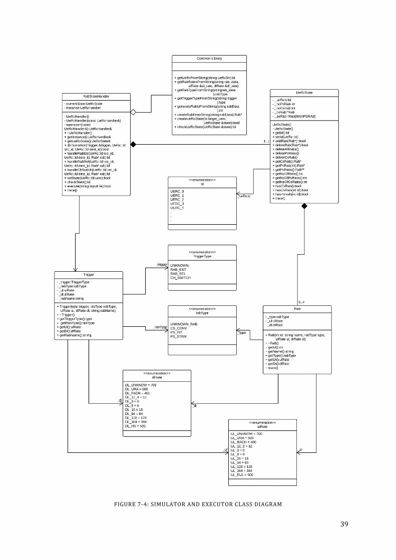
39
FIGURE 7-‐4: SIMULATOR AND EXECUTOR CLASS DIAGRAM

40
7.2.2 EXECUTOR
Executor is a Class which handles the state transitions by adding, deleting or changing an existing RAB. The executor code majorly lies in the following components: (+ public and -‐ private)
Class UeRcHandler: is a class which contains one UeRcState type attribute and few functions that assist in the handling of the state link doTranstion, handleRabEst, handleChSwitch etc.
• Data items o -‐ currentState:UeRcState o -‐ instance:UeRcHandler
• Member functions o -‐ UeRcHandler() o -‐ UeRcHandler(const UeRcHandler&) o -‐ operator=(const UeRcHandler&):UeRcHandler& o + ~UeRcHandler() o + getInstance():UeRcHandler& o + getUeRcState():UeRcState& o + doTransition(Trigger &trigger, UeRc::Id src_id, UeRc::Id dest_id):bool o + handleRabEst(UeRc::Id src_id, UeRc::Id dest_id, Rab* rab):Id o + handleRabRel(UeRc::Id src_id, UeRc::Id dest_id, Rab* rab):Id o + handleChSwitch(UeRc::Id src_id, UeRc::Id dest_id, Rab* rab):Id o + setState(UeRc::Id uerc):bool o + checkState():Id o + execute(string inputFile):bool o + trace()
Class Trigger: contains trigger type (Establish, Release and Channel Switch), along with the affected RAB Parameters (Type, Uplink, Downlink).
• Data items o -‐ _trigger:type o -‐ _rabType:rabType o -‐ _ul:ulRate o -‐ _dl:dlRate o -‐ _rabName:string
• Member Functions o -‐ Trigger() o + Trigger(type trigger, rabType rabType, ulRate ul, dlRate dl, string rabName) o + ~Trigger() o + getTriggerType():type o + getRabType():rabType o + getUl():ulRate o + getDl():dlRate o + getRabName():string
Common Library: is a library that contains some general functionality which is used commonly by the executor to manipulate the data extracted from the input UeRc transition table file.

41
• Function List (static/global functions) o getUeRcFromString(string ueRcStr):Id o getRabRatesFromString(string rab_data, ulRate &ul_rate, dlRate &dl_rate) o getRabTypeFromString(string rab_data):rabType o getTriggerTypeFromString(string trigger):type o generateRabIdFromString(string rabData):int o createRabFromString(string rabData):Rab* o createUeRcState(Id target_uerc, UeRcState &state):bool O checkUeRcState(UeRcState &state):Id
7.2.3 WORKING OF TEST CASE EXECUTOR
Despite the technical complexities of the implementation of the test case executor, the working of test cases executor is kept simple so running the test suite should not be problematic. The behavior of executor is to take in the transition table generated by the transition table generator script as input. Then the transition is parsed line by line. Each line contains the following information
• Source/Current State • Target State • Triggers • Affected RAB
UeRc:0;UeRc:2;RAB_EST;CONV_CS_SPEECH(12.2/12.2)
The UeRcHandler class reads this input and splits it in to four parameters in the execute method
• Source State = UERC0 • TargetState = UERC2 • TriggerType = RAB_EST • RAB
o Type = CONV_CS_SPEECH o Ul = 12.2 o Dl = 12.2
Helper functions are used to convert the text in to enums and integer values. Once this is done a function call is invoked to doTransition method which perform the desired transition by creating a specific trigger and passing it to the simulator classes. When simulator finishes its execution, a check is made to verify if the transition was successful or not. This method further invokes three other possible methods
• handleRabEst: to handle the RAB establish cases. • handleRabRel: to handle the RAB release cases. • handleChSwitch: to handle the Channel switching cases.
All of the above methods invoke different functionalities of the simulator to perform the transition. The simulator in this term behaves like the actual system and will only do the transition if possible. Each of the methods returns the resultant UeRc state which is then compared with the TargetState parameters extracted from the transition table. This validation is done in doTransition method as mentioned before.
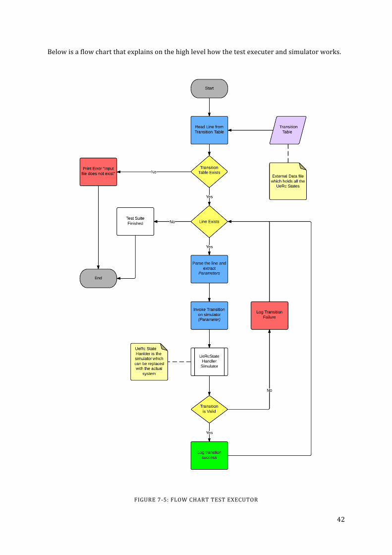
42
Below is a flow chart that explains on the high level how the test executer and simulator works.
FIGURE 7-‐5: FLOW CHART TEST EXECUTOR

43
8 RESEARCH OUTCOMES AND EVALUATION
This chapter gives some answers to the research question mentioned in 1.4 and gives feedback on the outcome of this research.
8.1 MAIN OUTCOMES
The purpose of this research was purely to find a solution to the highlighted problem. Based on the problem description and detailed system analysis, these are the outcomes from this research.
8.1.1 IN DEPTH STUDY OF THE PROBLEM.
First step was to have a detailed insight of the system under analysis and identify the major problem. This has been done by reading system documentation and performing detailed code walkthrough of the system (the test framework currently running). As described in chapter 6, the problem under study is state explosion in the existing FSM based SUT which makes it very difficult to perform manual testing of different possible transitions. There is no good way to avoid this problem as the system logic is designed in this way and this is the expected behavior from the system. It is the test framework that needs some automation so that it can identify different possible transitions by itself and try to execute them to make sure that these transitions work properly.
In section 7 a solution sketch is provided to this problem. The problem has been split in two parts where the first part takes in all the system states as input. It identifies possible outgoing transitions from each state and finally stores them in an output file. The second part takes the output generated by the previous stage as input and performs all those transitions. It behaves both like a simulator and a test executor, which ensures each transition in the transition table works.
This is the answer to the very first research question “Is it possible to automate the test suite to traverse all possible transition?” The provided solution handles the RAB Establish and RAB Release cases as expected. No matter how many states are added or removed the algorithm produces correct number of test cases. There is a minor complication in the Channel Switch cases where it gets complex in handling all possible combinations especially like; switching to the common channels (RACH/FACH), switching to high speed channels (EUL/HS) or going to sleep mode (URA/URA) states. However, the solution sketch is still valid; it is only the implementation of Transition table generator to handle the special cases.
8.1.2 IMPLEMENT THE SKETCHED SOLUTION ON A SMALL SCALE.
Once the solution is sketched and the algorithms are developed while answering the first question, next phase is to implement the design. Implementation of first part is done in Java (see 7.1.3 for details).
Implementation of second phase, the test cases executor, is done in C++. It contains further two sections:
• One is the simulator behaving as the actual system (see 7.2.1). • Other is executor which executes all the transition from the transition table generated
by Java code (see 7.2.2).

44
The solution is sketched for the whole problem whereas the implementation is only done for a smaller sample of data. This is done to reduce the implementation complexity and still check the effectiveness of the solution (which is explained later) before applying it on a large scale.
The second outcome helps in answering the second research question “Can the automated test suite adapt to the changes in the system by addition or removal of states?” after implementation of the solution on a smaller scale sample data. It can be observed that the system is behaving as it is expected to do.
TABLE 8-‐1: EXPECTED VS. GENERATED NO.OF TRANSITION TABLE
Input States No.of States No.of expected transitions
(theoretically)
No.of transition generated by script
UeRc:0 UeRc:2
2 2 2
UeRc:0 UeRc:2 UeRc:5
3 4 4
UeRc:0 UeRc:2 UeRc:5 UeRC:10
4 8 8
UeRc:0 UeRc:2 UeRc:4 UeRc:5 UeRc:10
5 12 12
UeRc:0 UeRc:2 UeRc:4 UeRc:5 UeRc:10 UeRc:25
6 18 18
UeRc:0 UeRc:2 UeRc:4 UeRc:5 UeRc:10 UeRc:25 UeRc:26
7 20 20
UeRc:0 UeRc:2 UeRc:4 UeRc:5 UeRc:10 UeRc:25 UeRc:26 UeRc:62
8 22 22
In Table 8-‐1, based on the input (states and number of states) 3rd column is expected outcome that has been calculated using theoretical calculation8 which is then compared to the 4th column 8 Expected outputs are the transitions that are calculated based on the system behavior that what is expect from the system. Some of these are used in the currently implemented manual test framework.

45
that is outcome generated by the implemented solution. Equality in between these two columns demonstrates that the script is producing the expected output. Some of the outputs are explained in the next sections. The simulator used in the test executor takes the generated transition as input and do the transitions as specified by adding, removing or channel switching. The new achieved state is then matched with the reference UeRc file (same file that is used to generate the table) to see if the achieved state really exists which verifies the correctness of the generated transition table. If any of the generated states does not exist in the reference UeRc file, this will be a bug in the transition table generator script but so far nothing has been observed with the currently provided input set.
8.1.3 EFFECTIVENESS OF THE PROPOSED SOLUTION.
To verify the effectiveness of the solution, the outputs need to be evaluated. As seen in Table 8-‐1, test script is already generating desired number of transition based on the input. Looking in to some of the input vs output comparison below;
TABLE 8-‐2: 3-‐STATE BASE TRANSITION TABLE
Input
3-‐States
UeRc:0 #[Idle] UeRc:2 #[Conversational CS Speech (12.2/12.2)] UeRc:5 #[Interactive PS (64/64)]
Output
Source Target Trigger Affected RAB UeRc:0 UeRc:2 RAB_EST CONV_CS_SPEECH(12.2/12.2) UeRc:0 UeRc:5 RAB_EST INT_PS(64/64) UeRc:2 UeRc:0 RAB_REL CONV_CS_SPEECH(12.2/12.2) UeRc:5 UeRc:0 RAB_REL INT_PS(64/64)
TABLE 8-‐3: 5-‐STATE BASE TRANSITION TABLE
Input
5-‐States UeRc:0 #[Idle] UeRc:2 #[Conversational CS Speech (12.2/12.2)] UeRc:4 #[Interactive PS (RACH/FACH)] UeRc:5 #[Interactive PS (64/64)] UeRc:10 #[Conversational CS Speech (12.2/12.2) + Interactive PS (64/64)]
Output Source Target Trigger Affected RAB UeRc:0 UeRc:2 RAB_EST CONV_CS_SPEECH(12.2/12.2) UeRc:0 UeRc:4 RAB_EST INT_PS(RACH/FACH) UeRc:0 UeRc:5 RAB_EST INT_PS(64/64) UeRc:2 UeRc:0 RAB_REL CONV_CS_SPEECH(12.2/12.2) UeRc:2 UeRc:10 RAB_EST INT_PS(64/64) UeRc:4 UeRc:0 RAB_REL INT_PS(RACH/FACH) UeRc:4 UeRc:5 CH_SW PS_INT (64/64) UeRc:5 UeRc:0 RAB_REL INT_PS(64/64)

46
UeRc:5 UeRc:4 CH_SW PS_INT (RACH/FACH) UeRc:5 UeRc:10 RAB_EST CONV_CS_SPEECH(12.2/12.2) UeRc:10 UeRc:2 RAB_REL INT_PS(64/64) UeRc:10 UeRc:5 RAB_REL CONV_CS_SPEECH(12.2/12.2)
TABLE 8-‐4: 8-‐STATE BASE TRANSITION TABLE
Input
8-‐States UeRc:0 #[Idle] UeRc:2 #[Conversational CS Speech (12.2/12.2)] UeRc:4 #[Interactive PS (RACH/FACH)] UeRc:5 #[Interactive PS (64/64)] UeRc:10 #[Conversational CS Speech (12.2/12.2) + Interactive PS (64/64)] UeRc:25 #[Interactive PS (EUL/HS)] UeRc:26 #[Interactive PS (64/64) + Interactive PS (64/64)] UeRc:62 #[Interactive PS (EUL/HS) + Interactive PS (EUL/HS)]
Output
Source Target Trigger Affected RAB UeRc:0 UeRc:2 RAB_EST CONV_CS_SPEECH(12.2/12.2) UeRc:0 UeRc:4 RAB_EST INT_PS(RACH/FACH) UeRc:0 UeRc:5 RAB_EST INT_PS(64/64) UeRc:0 UeRc:25 RAB_EST INT_PS(EUL/HS) UeRc:2 UeRc:0 RAB_REL CONV_CS_SPEECH(12.2/12.2) UeRc:2 UeRc:10 RAB_EST INT_PS(64/64) UeRc:4 UeRc:0 RAB_REL INT_PS(RACH/FACH) UeRc:4 UeRc:5 CH_SW PS_INT (64/64) UeRc:4 UeRc:25 CH_SW PS_INT (EUL/HS) UeRc:5 UeRc:0 RAB_REL INT_PS(64/64) UeRc:5 UeRc:4 CH_SW PS_INT (RACH/FACH) UeRc:5 UeRc:10 RAB_EST CONV_CS_SPEECH(12.2/12.2) UeRc:5 UeRc:25 CH_SW PS_INT (EUL/HS) UeRc:5 UeRc:26 RAB_EST INT_PS(64/64) UeRc:10 UeRc:2 RAB_REL INT_PS(64/64) UeRc:10 UeRc:5 RAB_REL CONV_CS_SPEECH(12.2/12.2) UeRc:25 UeRc:0 RAB_REL INT_PS(EUL/HS) UeRc:25 UeRc:4 CH_SW PS_INT (RACH/FACH) UeRc:25 UeRc:5 CH_SW PS_INT (64/64) UeRc:25 UeRc:62 RAB_EST INT_PS(EUL/HS) UeRc:26 UeRc:5 RAB_REL INT_PS(64/64) UeRc:62 UeRc:25 RAB_REL INT_PS(EUL/HS)
The information in Table 8-‐2, Table 8-‐3 and Table 8-‐4 are the generated transition tables from the script developed during this research. This is just a small sample of information showing input vs. output with 3, 5 and 8 states respectively. According to Algorithm 1 and Algorithm 2 defined in 7.1.1 and 7.1.2, the above generated outputs are as expected which shows the

47
accurate behavior of the transition generator script. Table 8-‐4 contains the transition for UeRc:25. These can be categorized in two types, incoming transition and outgoing transition.
Incoming Transitions are the one in which UeRc:25 is the target state and are highlighted as blue in the table.
1. From UeRc:0 it is possible to go to any single state RAB and UeRc:25 fulfills the criteria. 2. UeRc:4 it is possible to go to any state containing only one PS RAB using Channel
Switching and UeRc:25 has it. 3. From any states having only PS RAB can channel switch to UeRc:25, so UeRc:5 to
UeRc:25 is valid transition. 4. Finally UeRc:62 has two PS(EUL/HS ) RABs and UeRc:25 has one PS(EUL/HS)RAB so
releasing one RAB at UeRc:62 will make it UeRc:25.
Outgoing transition are the one in which UeRc:25 is the source state and are highlighted as green in the table. All the reverse transitions are possible.
1. From any single RAB states it is possible to go to Idle (UeRc:0). 2. From UeRc:25 Channel Switching to any states with only one PS RAB is possible so
transition to UeRc:4 and UeRc:5 is valid. 3. UeRc:25 has one PS(EUL/HS) RAB, RAB establish with one more PS(EUL/HS) will result
in UeRc:62.
All the above transitions are valid and have been verified by the system engineers by manually generating outputs. Only for UeRc:25 the incoming and outgoing transitions have been explained.
8.2 EVALUATION
Evaluation is the part where it is decide how much of the requirement have been fulfilled. MOMC based evaluation is performed in this research. Three main evaluation factors are taken into consideration.
8.2.1 OUTPUT VALIDATION
Here the output generated from the script is compared with the expected outputs. Looking through the tables Table 8-‐1, Table 8-‐2, Table 8-‐3 and Table 8-‐4 it can be observed that the generated output has same number of output transition as theoretically calculated. Secondly the output is valid because all the generated transitions result in to a valid states that are defined in the system. The simulator is developed in a way to only perform the transition if it ends up in a valid state. If any input transition leads to a state that does not exist in the systems valid state table (the states input file), the simulator will go to an invalid state which will be a failure. So the simulator itself behaves as the validator of the transition table generated by the script.
8.2.2 IMPLEMENTATION COMPLEXITY
Complexity of the implementation depends on how much coupling is there between the generated solution and SUT. The advantage with the implementation in this research is that it provides the code for executor that runs transition tests. It also provides the simulator code which has some improvements that can be implemented in the test environment to improve its usability.

48
There are three part of implementation
1. Transition Table Generator (Java) 2. Simulator (C++) 3. Executor (C++)
The transition table generator is independent of any existing implementation of RAB State Handler used in the current system. It does not use any existing implementation except of the input UeRc State file. The purpose of this script is to generate the transition table based on the input file which can be used for any purpose including testing of states transition. This is completely isolated script so there is no additional implementation cost in this case only the output generated transition table file is needed for testing. However the transition table generator script has been implemented on a small set of input values. It needs update to handle the remaining UeRcs which contains PS Streaming RAB.
Simulator is just the C++ code that is intended to behave as the actual system. During the implementation of this described solution in the RAB State Handler, the Simulator part shall be replaced with the official RAB State Handler which will actually execute the production code on the system and do the state transition which then will be verified by the test system. Simulator part is coded because the actual RAB State Handler is very complex, contains thousands of lines of code and it is Ericsson proprietary. But the simulator also behaves as a validator for the generated transition table as mentioned in 8.2.1.
Executor is the part that needs to be implemented in the RAB States Handler test environment so that the system will be able to take the transition table as input file, then one by one feed this to the RAB States handler (instead of Simulator) and verifies the expected outcome. Implementation should be straight forward and can be done with steps.
1. Copy the code of the Executor (UeRcHandler Class) in the RAB State Handlers test package.
2. Update the inclusion from simulated classes (UeRc States, RAB) to the actual classes.
8.2.3 MAINTAINABILITY OVERHEAD
Finally comes the maintainability overhead which is the estimate of how much work needs to be done in order to keep the proposed solution update to date. The only thing that effects the proposed solution is addition of new state. There can be two reasons for that;
1. New RAB Combination (State) introduced. 2. New RAB introduced which will create new RAB Combinations (States).
Addition or removal of states does not require any maintenance as the script will automatically handle the new state input file and the transition table will be generated accordingly. On the other hand for second case when a new RAB is introduced to the system e.g. a new Packet RAB with higher bit rates, this will require update in the script as the RAB information is stored in the script itself. The new RAB and associated rules should be added in the script in order to handle transitions to possible states. These kind of changes come from 3GPP and most likely these do not happen very often because most standards are already defined. Still there are possibilities and updates are required accordingly. Figure 8-‐1 shows the maintenance overview of the system. On addition of a new RAB in the system, on impact will be on the TransitionAnalysis class in the Transition Table Generator. Whereas there is no impact on the executor at all. However as the SUT has been updated there will be minor changes in the RAB
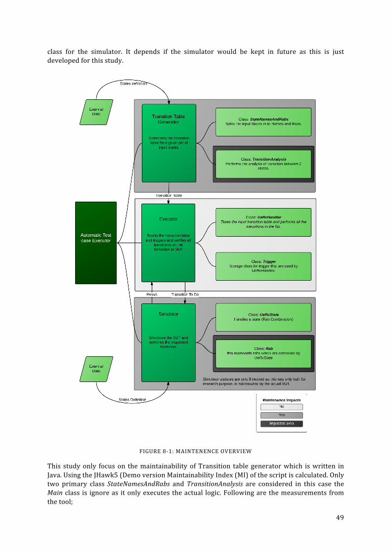
49
class for the simulator. It depends if the simulator would be kept in future as this is just developed for this study.
FIGURE 8-‐1: MAINTENENCE OVERVIEW
This study only focus on the maintainability of Transition table generator which is written in Java. Using the JHawk5 (Demo version Maintainability Index (MI) of the script is calculated. Only two primary class StateNamesAndRabs and TransitionAnalysis are considered in this case the Main class is ignore as it only executes the actual logic. Following are the measurements from the tool;
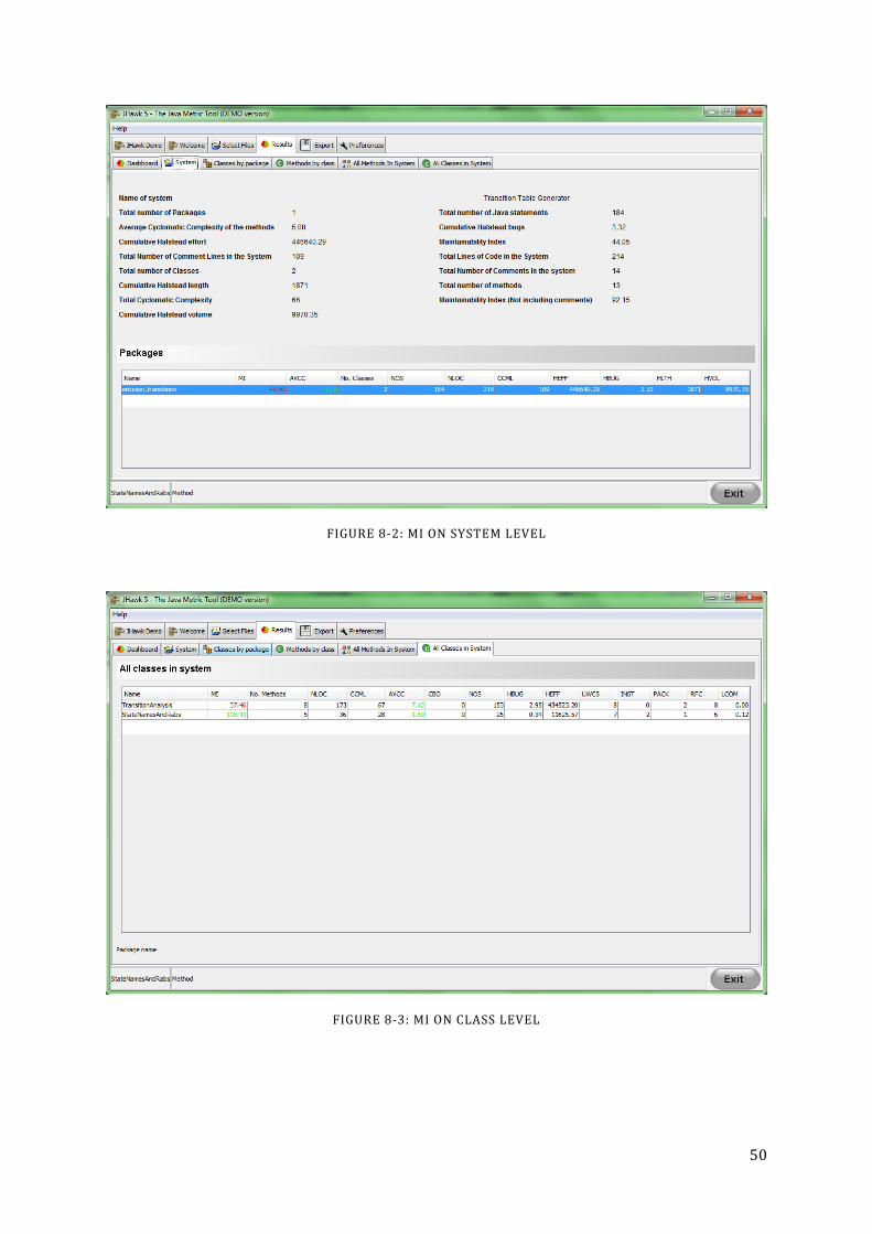
50
FIGURE 8-‐2: MI ON SYSTEM LEVEL
FIGURE 8-‐3: MI ON CLASS LEVEL

51
FIGURE 8-‐4: COMPLEXITY ON METHOD LEVEL
Figure 8-‐2, Figure 8-‐3 and Figure 8-‐4 shows that the MI is 44.05 which is quite low due to the reason of high complexity in TransitionAnalysis class. Methods checkIfTransitionIsPossible, listOfTransition and fixOutput are the most complex ones. The method checkIfTransitionIsPossible is the one making most of the decisions and checking if a transition between two states is valid or not.
Other metric that we considered is the volume that is LOC. From Figure 8-‐2 we can see there the total LOC is 214 which is quite small.
FIGURE 8-‐5: RANKING SCHEME VS LOC [26]
In Figure 8-‐5 KLOC is Kilo Line of code, MY is Man Years, rank is how much code is maintainable based on LOC. ++ is the best and -‐-‐ is the worst [26]. As Transition table generator is writing in Java with only 214 LOC. It lies on the top of the list giving it a ++ which gives a fairly good idea about maintainability effort.

52
9 DISCUSSION
This chapter will give some idea to future researcher how to continue this research to the next step and will highlight some limitation.
9.1 REFLECTIONS
Methodology used in this research is a basic divide and concur approach. As this research is not just a theoretical study of the 3G RNC UeRc State Handler but also implementation is involved for proposed solution. The information available in the product documentation is highly coupled with other aspects which are not part of this research. Both documentation and code review is done in order to understand the system and associated problem. Also a few meetings were carried out with the area experts including the research supervisor in order to get a clear picture. The divide and concur approach made it a lot easy in breaking down the problems into smaller units. So the focus can be set to one issue at a time.
FIGURE 9-‐1: PROBLEM BREAKDOWN
References used in the research are mostly to understand and clarify the theoretical background. Ericsson internal documents and code that is used to understand the problem are not mentioned in the references section. These documents were only used to understand the system and underlying problem which is described in more generic format using state machines. The references can be categorized in four groups based on the theoretical sections in which they are used.
1. State Machines and State Explosion Problem. 2. Logic and Discrete Mathematics. 3. Software testing and Test Automation. 4. WCDMA Networks.
All these references in the reference list are to support reader’s understanding of the theoretical sections and make the background more clear so the problem description and solution specification can be easily understood. As this problem is specific to Ericsson’s network, it was not possible to find some similar research that would exactly fit this case. Few other thesis reports were read related to automated test cases generation from software documentation but were not used. This solution is designed from scratch so there are no references for the solution section.

53
9.2 LIMITATIONS
This study has the following limitations and future improvements.
1. This research is based on a very specific tests system at Ericsson but this solution can provide good guide lines to similar issues which involves state machines.
2. The solution provided in this research is based on a small sample extracted from the actual data that is represented in a simulated system but with some extra effort the solution can scaled to the whole system (See 8.2.2).
3. Most of the information handled in this research is Ericsson Confidential and cannot be shared publicly that is why some data samples and mostly open standards like 3GPP are used to represent the problem and its solution.
4. To reduce the complexity and time required for the research Connection Capabilities handling has been left out of this research with agreement of Ericsson.
5. Transition table generator script helps a lot in generating the transition table which is very useful for testing but the script needs maintenance and need to be updated if a new type of RAB is introduced.
6. Maintainability Index has been calculated using the third party tool. Accuracy of that tool has not been verified.
9.3 FUTURE WORK
For future updates once the proposed solution is completely implemented, the next step would be to target connection capabilities on each state. Each state with a PS RAB has a possibility to have several connection capabilities like MIMO (Multiple input multiple output) and a few others. It would be a beneficial improvement if the test system can be extended to the next level handling these connection capabilities.
Transition table generator has high complexity.
9.4 ETHICAL ASPECTS
This research is purely technical and provides solution that can be implemented in the test framework which already exists. The purpose of this research is to make life easy for developer not to put too much effort in writing manual test cases instead he/she can put more focus on the production code that is profitable for the company.
Data used for analysis which is Ericsson proprietary has first been translated according to 3GPP standards so it can be represented as generic information which is common for all WCDMA and 3G technology. No Ericsson internal or confidential data and documents has been exposed to external reader but has been referred as 3GPP standards.
9.5 ENVIRONMENTAL ASPECTS
There are no negative environmental aspects as the solution provided by this research will be implemented as a part of existing system. Theoretically is should decrease the time of implementing manual test cases by automatically executing expected scenarios which will not have any impact on the environment.
From safety and security point of view there can be one possible impact that the emergency call RAB/RAB Combination gets miss handled if the testing is not done properly. So it is

54
recommended that emergency call test cases should be handled with extra care and it would be better to add few more test cases for this scenario.
55
10 CONCLUSIONS
The research’s main focus was to sketch a solution to the testing of different states in Ericsson’s RAB state handler. During the research two main components were developed;
1. Transition Table Generator. 2. Automated Executor,
a. Simulator. b. Executor.
Now let’s have look at the research question that should be answered with the outcomes of this research
• Is it possible to automate the basic test framework to traverse maximum possible transitions?
In this research a limited number of states and RABs associated with have been taken. The transition table generator needs to know about the RAB types those are involved in any state in order to perform the transition. The current implementation covers roughly 70% of the possible transition. As the PS Streaming RAB has been excluded from this research for simplification, adding that in the system will make the transition table generator script work for the complete system. So implementation and evaluation results supports that it is possible to make a script that can traverse all the states and generate a transition table that can be used for test input.
• Can the automated test framework adapt to the changes in the system, such as addition or removal of states?
Second question is about adoptability for changes. From the outcomes section 8.1.2 it can observed that the script is generating right number of output transition and from 8.1.3 it can be further seen that script is able to adopt automatically as the states are being added to the system. As far as the new state is added with the RAB types which already exist, script will handle those automatically. The script only needs to be updated when there is a new RAB type introduced.
• Will this automation be effective both in terms of time and cost?
Looking through the research outcome it can be observed that this research has fulfilled most of the requirements,
1. There is a script generation possible transition table. 2. There is an executor part that can work with both the simulator and the actual SUT to
executes the transition and verify them.
But there are a few things that impact the feasibly of implementation and maintainability of the solution on the actual SUT. Transition table generator need update to handle all possible RAB type that can add extra work in order to test the complete system. Even though the MI is low which means high maintenance effort still the LOC is very few which makes it simple to maintain. Overall the solution is accepted by the development team. It will require at least two developer a minimal dedicated time of two months in order to complete the left over parts and make it fully functional for all possible UeRc states. Once the solution is completely implemented there is a small cost of maintaining the transition table generator only if a new UeRc state is added with a new type of RAB, with existing type of RABs, the solution will work without any change.

56

57
11 BIBLIOGRAPHY
[1] Shilei Liu and B. Eng., "Generating Test Cases From Software Documentation," Department of Electrical and Computer Engineering, McMaster University, Hamilton, Ontario, Thesis Report 2001.
[2] Menqi Wu Kanglin Li, Effective Software Test Automation: Developing an Automated Software Testing Tool. Chicago: Sybex, 2004.
[3] Anand Saswat et al., "An orchestrated survey of methodologies for automated software test case generation," Journal of Systems and Software, vol. 86, pp. 1978-‐2001, August 2013.
[4] Jan Tretmans, "Model Based Testing with Labelled Transition Systems," in Formal Methods and Testing.: Springer Berlin Heidelberg, 2008, vol. 4949, pp. 1-‐38. [Online]. http://dx.doi.org/10.1007/978-‐3-‐540-‐78917-‐8_1
[5] Robert Binder, Testing Object-‐oriented Software Testing: Models, Patterns, and Tools.: Addison-‐Wesley, 1999.
[6] Thomas Koshy, Discrete Mathematics With Applications.: Elsevier Academic Press, 2004.
[7] Patrick R. Schaumont, A Practical Introduction to Hardware/Software Codesign, 2nd ed. New York: Springer, 2013.
[8] Wagner Ferdinand, Schmuki Ruedi, Wagner Thomas, and Wolstenholme Peter, Modeling Software with Finite State Machines: A Practical Approach.: CRC Press, 2006, vol. 0.
[9] Lee Copeland, A Practitioner's Guide to Software Test Design. London: Arech House, 2004.
[10] Hong Zhu, Patrick A. V. Hall, and John H. R. May, "Software unit test coverage and adequacy," ACM Computing Surveys, vol. 29, no. 4, pp. 366–427, December 1997. [Online]. http://doi.acm.org/10.1145/267580.267590
[11] Bertolino and Antonia, "Software Testing Research: Achievements, Challenges, Dreams," in Future of Software Engineering, FOSE '07, Minneapolis, 2007, pp. 85 -‐ 103. [Online]. http://ieeexplore.ieee.org/stamp/stamp.jsp?tp=&arnumber=4221614&isnumber=4221601
[12] Conformiq. (2013) Why Automate Test Design?. [Online]. http://www.conformiq.com/cqwp-‐atd.pdf
[13] Elfriede Dustin, Thom Garrett, and Bernie Gauf, Implementing Automated Software Testing: How To Save Time and Lower Costs While Rasising Quality. Massachusetts: Pearson Education, 2009.
[14] Carl J. Nagle. (2012, August) Test Automation Frameworks. [Online]. http://safsdev.sourceforge.net/FRAMESDataDrivenTestAutomationFrameworks.htm
[15] King James C., "A new approach to program testing," Proceedings of the international conference on Reliable software, vol. 10, no. 6, pp. 228-‐233, June 1975. [Online].

58
http://doi.acm.org/10.1145/800027.808444
[16] S. Khurshid, C. Pasareanu, and W. Visser, "Generalized Symbolic Execution for Model Checking and Testing," in Tools and Algorithms for the Construction and Analysis of Systems, Hubert Garavel and John Hatcliff, Eds. Warsaw, Poland: Springer Berlin Heidelberg, 2003, vol. 2619, pp. 553-‐568. [Online]. http://dx.doi.org/10.1007/3-‐540-‐36577-‐X_40
[17] Castro Miguel, Costa Manuel, and Martin Jean-‐Philippe, "Better bug reporting with better privacy," in Architectural support for programming languages and operating systems (ASPLOS XIII), New York, 2008, pp. 319-‐328. [Online]. http://doi.acm.org/10.1145/1346281.1346322
[18] P. Zhang, S. Elbaum, and M.B. Dwyer, "Automatic generation of load tests," in Automated Software Engineering (ASE), 2011, pp. 43,52. [Online]. http://ieeexplore.ieee.org/stamp/stamp.jsp?tp=&arnumber=6100093&isnumber=6100039
[19] Qi Dawei, Roychoudhury Abhik, Liang Zhenkai, and Vaswani Kapil, "Darwin: an approach for debugging evolving programs," in The foundations of software engineering (ESEC/FSE '09), New York, 2009, pp. 33-‐42. [Online]. http://doi.acm.org/10.1145/1595696.1595704
[20] R. Santelices, P.K. Chittimalli, T. Apiwattanapong, A Orso, and M.J. Harrold, "Test-‐Suite Augmentation for Evolving Software," in Automated Software Engineering, 2008. ASE 2008. 23rd IEEE/ACM International Conference, L'Aquila, 2008, pp. 218-‐227. [Online]. http://ieeexplore.ieee.org/stamp/stamp.jsp?tp=&arnumber=4639325&isnumber=4639293
[21] Marie-‐Claude Gaudel, "Testing can be formal, too," in Theory and Practice of Software Development. Orsay: Springer Berlin Heidelberg, 1995, vol. 915, pp. 82-‐96. [Online]. http://dx.doi.org/10.1007/3-‐540-‐59293-‐8_188
[22] Conformiq. http://www.conformiq.com/. [Online]. http://www.conformiq.com/products/feature-‐specifications/
[23] Sumit Kasera and Nishit Narang, 3G Mobile Networks. United States of America: McGraw-‐Hill, 2005.
[24] 3GPP, "Typical examples of RABs and RBs supported by UTRA," Technical Report 2009. [Online]. http://www.3gpp.org/DynaReport/25993.htm
[25] D.I.K. Sjoberg, B. Anda, and A. Mockus, "Questioning software maintenance metrics: A comparative case study," in Empirical Software Engineering and Measurement, Lund, 2012 , pp. 107-‐110.
[26] I. Heitlager, T. Kuipers, and J. Visser, "A Practical Model for Measuring Maintainability," in Quality of Information and Communications Technology, Lisbon, 2007, pp. 30-‐39.

59
12 GLOSSARY
Here is the list of abbreviations used in this research;
AN Access Network CBA Cost Benefit Analysis CH_SW Channel Switch (Trigger) CN Core Network CS Circuit Switched EUL Enhanced Uplink DDT Data-‐Driven Testing FSM Finite State Machine GBR Guaranteed Bit Rate HS High Speed (Downlink) LOC Lines of Code LTS Labelled Transition System MBR Maximum Bit Rate MBT Model Based Testing MI Maintainability Index MIMO Multiple Input Multiple Output MOMC Multi Objective Multi Criteria PS Packet Switch QoS Quality of Service RAB Radio Access Bearer RAB_EST RAB Establish (Trigger) RAB_REL RAB Release (Trigger) RDC RAB Difference Criteria RNC Radio Network Controller SM Structure Measurements SUT System Under Test TDD Test-‐Driven Development TDMA Time Division Multiple Access UE User Equipment Iub Interface between NodeB and RNC Iur Interface between RNC and RNC Iu Interface between RNC and CN IuPS Interface between RNC and CN with PS service IuCS Interface between RNC and CN with CS service UE User Equipment UeRc User Equipment Radio Connection UMTS Universal Mobile Telecommunication System WCDMA Wideband Code Division Multiple Access

60
13 LIST OF FIGURES
Figure 1-‐1: Simple State machine ............................................................................................................................... 3 Figure 1-‐2: 3-‐States State machine ............................................................................................................................. 4 Figure 1-‐3: 4-‐States Statemachine .............................................................................................................................. 4 Figure 2-‐1: State Machine of Turnstile ..................................................................................................................... 6 Figure 2-‐2: 3-‐State FSM ................................................................................................................................................... 7 Figure 2-‐3: 4-‐State FSM ................................................................................................................................................... 8 Figure 2-‐4: 6-‐State FSM ................................................................................................................................................... 9 Figure 3-‐1: Manual Testing [12] ................................................................................................................................ 12 Figure 3-‐2: Symbolic Execution Flow [3] [16] ..................................................................................................... 14 Figure 3-‐3: Candy Machine LTS [4] .......................................................................................................................... 16 Figure 3-‐4: DDT execution Flow ................................................................................................................................ 17 Figure 4-‐1: Umts Overview .......................................................................................................................................... 18 Figure 4-‐2: RAB Types and Radio Connection ..................................................................................................... 19 Figure 4-‐3: UMTS QoS Architecture [24] ............................................................................................................... 20 Figure 6-‐1: UeRc State Explosion .............................................................................................................................. 25 Figure 7-‐1: Solution Breakdown ............................................................................................................................... 28 Figure 7-‐2: Establish and Release State machine ............................................................................................... 31 Figure 7-‐3: Channel Switcing State machine ........................................................................................................ 33 Figure 7-‐4: Simulator and Executor Class Diagram .......................................................................................... 39 Figure 7-‐5: Flow Chart Test Executor ..................................................................................................................... 42 Figure 8-‐1: Maintenence Overview .......................................................................................................................... 49 Figure 8-‐2: MI on System Level .................................................................................................................................. 50 Figure 8-‐3: MI on Class level ....................................................................................................................................... 50 Figure 8-‐4: Complexity on Method Level ............................................................................................................... 51 Figure 8-‐5: Ranking Scheme VS LOC [26] .............................................................................................................. 51 Figure 9-‐1: Problem Breakdown ............................................................................................................................... 52

61
14 LIST OF TABLES
Table 2-‐1: Trnsition Table of Turnstile [6] ............................................................................................................. 7 Table 2-‐2: Transition Table for 3-‐State FSM .......................................................................................................... 8 Table 2-‐3: Transition Table for 4-‐State FSM .......................................................................................................... 8 Table 2-‐4: Transition Table for 6-‐State FSM ........................................................................................................ 10 Table 4-‐1: Traffic Classes [24] .................................................................................................................................... 21 Table 4-‐2: Interactive bitrate [24] ............................................................................................................................ 21 Table 4-‐3: UeRc List ........................................................................................................................................................ 22 Table 6-‐1: 8-‐States Based Transition Table .......................................................................................................... 26 Table 7-‐1: Initial Input Data ........................................................................................................................................ 29 Table 7-‐2: Actual Input Data (No SRB) ................................................................................................................... 29 Table 7-‐3: Output format of Script ........................................................................................................................... 35 Table 8-‐1: Expected Vs. Generated No.Of Transition Table ........................................................................... 44 Table 8-‐2: 3-‐State Base Transition Table ............................................................................................................... 45 Table 8-‐3: 5-‐State Base Transition Table ............................................................................................................... 45 Table 8-‐4: 8-‐State Base Transition Table ............................................................................................................... 46

62

63
APPENDIX -‐ A
A-‐1 TOOLS AND LANGUAGES
Tools and languages used to support this research.
• Eclipse • Notepad++ • Java • C++ • JHawk5 (Demo Version)
A-‐2 UERC REFERNCE FILE
Below is the list of UeRcs (RAB Combinations) currently used by the system for which this research is conducted. This is a unique representation of each RAB Combination as a state for easy handling.
UeRc:0 #[Idle]
UeRc:1 #[SRB (13.6/13.6)]
UeRc:2 #[Conversational CS Speech (12.2/12.2)]
UeRc:3 #[Conversational CS Unknown (64/64)]
UeRc:4 #[Interactive PS (RACH/FACH)]
UeRc:5 #[Interactive PS (64/64)]
UeRc:6 #[Interactive PS (64/128)]
UeRc:7 #[Interactive PS (64/384)]
UeRc:8 #[Streaming CS Unknown (57.6/57.6)]
UeRc:9 #[Conversational CS Speech (12.2/12.2) + Interactive PS (0/0)]
UeRc:10 #[Conversational CS Speech (12.2/12.2) + Interactive PS (64/64)]
UeRc:11 #[SRB (13.6/13.6), Preconfigured]
UeRc:12 #[Conversational CS Speech (12.2/12.2), Preconfigured]
UeRc:13 #[Streaming PS Unknown (16/64) + Interactive PS (8/8)]
UeRc:14 #[Conversational CS Unknown (64/64) + Interactive PS (8/8)]
UeRc:15 #[Interactive PS (64/HS)]
UeRc:16 #[Interactive PS (384/HS)] //Increased due to PS (16/HS)
UeRc:17 #[Streaming PS Unknown (16/128) + Interactive PS (8/8)]
UeRc:18 #[Interactive PS (128/128)]
UeRc:19 #[Conversational CS Speech (12.2/12.2) + Interactive PS (64/HS)]
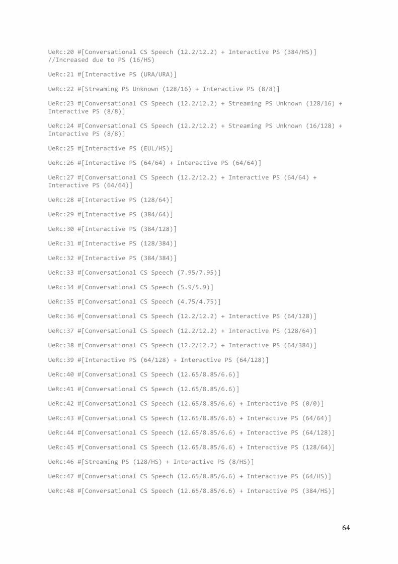
64
UeRc:20 #[Conversational CS Speech (12.2/12.2) + Interactive PS (384/HS)] //Increased due to PS (16/HS)
UeRc:21 #[Interactive PS (URA/URA)]
UeRc:22 #[Streaming PS Unknown (128/16) + Interactive PS (8/8)]
UeRc:23 #[Conversational CS Speech (12.2/12.2) + Streaming PS Unknown (128/16) + Interactive PS (8/8)]
UeRc:24 #[Conversational CS Speech (12.2/12.2) + Streaming PS Unknown (16/128) + Interactive PS (8/8)]
UeRc:25 #[Interactive PS (EUL/HS)]
UeRc:26 #[Interactive PS (64/64) + Interactive PS (64/64)]
UeRc:27 #[Conversational CS Speech (12.2/12.2) + Interactive PS (64/64) + Interactive PS (64/64)]
UeRc:28 #[Interactive PS (128/64)]
UeRc:29 #[Interactive PS (384/64)]
UeRc:30 #[Interactive PS (384/128)]
UeRc:31 #[Interactive PS (128/384)]
UeRc:32 #[Interactive PS (384/384)]
UeRc:33 #[Conversational CS Speech (7.95/7.95)]
UeRc:34 #[Conversational CS Speech (5.9/5.9)]
UeRc:35 #[Conversational CS Speech (4.75/4.75)]
UeRc:36 #[Conversational CS Speech (12.2/12.2) + Interactive PS (64/128)]
UeRc:37 #[Conversational CS Speech (12.2/12.2) + Interactive PS (128/64)]
UeRc:38 #[Conversational CS Speech (12.2/12.2) + Interactive PS (64/384)]
UeRc:39 #[Interactive PS (64/128) + Interactive PS (64/128)]
UeRc:40 #[Conversational CS Speech (12.65/8.85/6.6)]
UeRc:41 #[Conversational CS Speech (12.65/8.85/6.6)]
UeRc:42 #[Conversational CS Speech (12.65/8.85/6.6) + Interactive PS (0/0)]
UeRc:43 #[Conversational CS Speech (12.65/8.85/6.6) + Interactive PS (64/64)]
UeRc:44 #[Conversational CS Speech (12.65/8.85/6.6) + Interactive PS (64/128)]
UeRc:45 #[Conversational CS Speech (12.65/8.85/6.6) + Interactive PS (128/64)]
UeRc:46 #[Streaming PS (128/HS) + Interactive PS (8/HS)]
UeRc:47 #[Conversational CS Speech (12.65/8.85/6.6) + Interactive PS (64/HS)]
UeRc:48 #[Conversational CS Speech (12.65/8.85/6.6) + Interactive PS (384/HS)]
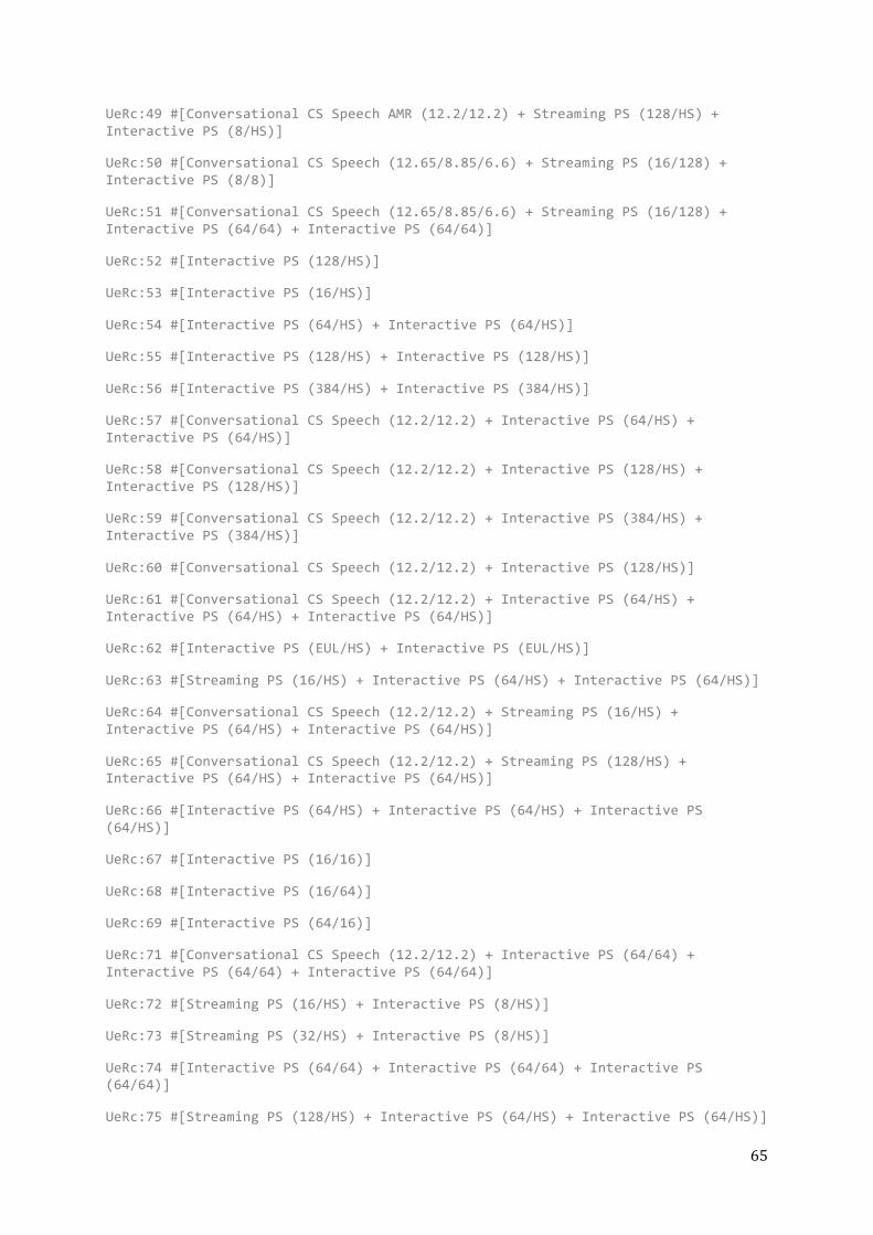
65
UeRc:49 #[Conversational CS Speech AMR (12.2/12.2) + Streaming PS (128/HS) + Interactive PS (8/HS)]
UeRc:50 #[Conversational CS Speech (12.65/8.85/6.6) + Streaming PS (16/128) + Interactive PS (8/8)]
UeRc:51 #[Conversational CS Speech (12.65/8.85/6.6) + Streaming PS (16/128) + Interactive PS (64/64) + Interactive PS (64/64)]
UeRc:52 #[Interactive PS (128/HS)]
UeRc:53 #[Interactive PS (16/HS)]
UeRc:54 #[Interactive PS (64/HS) + Interactive PS (64/HS)]
UeRc:55 #[Interactive PS (128/HS) + Interactive PS (128/HS)]
UeRc:56 #[Interactive PS (384/HS) + Interactive PS (384/HS)]
UeRc:57 #[Conversational CS Speech (12.2/12.2) + Interactive PS (64/HS) + Interactive PS (64/HS)]
UeRc:58 #[Conversational CS Speech (12.2/12.2) + Interactive PS (128/HS) + Interactive PS (128/HS)]
UeRc:59 #[Conversational CS Speech (12.2/12.2) + Interactive PS (384/HS) + Interactive PS (384/HS)]
UeRc:60 #[Conversational CS Speech (12.2/12.2) + Interactive PS (128/HS)]
UeRc:61 #[Conversational CS Speech (12.2/12.2) + Interactive PS (64/HS) + Interactive PS (64/HS) + Interactive PS (64/HS)]
UeRc:62 #[Interactive PS (EUL/HS) + Interactive PS (EUL/HS)]
UeRc:63 #[Streaming PS (16/HS) + Interactive PS (64/HS) + Interactive PS (64/HS)]
UeRc:64 #[Conversational CS Speech (12.2/12.2) + Streaming PS (16/HS) + Interactive PS (64/HS) + Interactive PS (64/HS)]
UeRc:65 #[Conversational CS Speech (12.2/12.2) + Streaming PS (128/HS) + Interactive PS (64/HS) + Interactive PS (64/HS)]
UeRc:66 #[Interactive PS (64/HS) + Interactive PS (64/HS) + Interactive PS (64/HS)]
UeRc:67 #[Interactive PS (16/16)]
UeRc:68 #[Interactive PS (16/64)]
UeRc:69 #[Interactive PS (64/16)]
UeRc:71 #[Conversational CS Speech (12.2/12.2) + Interactive PS (64/64) + Interactive PS (64/64) + Interactive PS (64/64)]
UeRc:72 #[Streaming PS (16/HS) + Interactive PS (8/HS)]
UeRc:73 #[Streaming PS (32/HS) + Interactive PS (8/HS)]
UeRc:74 #[Interactive PS (64/64) + Interactive PS (64/64) + Interactive PS (64/64)]
UeRc:75 #[Streaming PS (128/HS) + Interactive PS (64/HS) + Interactive PS (64/HS)]
66
UeRc:76 #[Conversational CS Speech (12.2/12.2) + Interactive PS (128/128) + Interactive PS (128/128)]
UeRc:77 #[Conversational CS Speech (12.2/12.2) + Streaming PS (16/HS) + Interactive PS (8/HS)]
UeRc:78 #[Conversational CS Speech (12.2/12.2) + Streaming PS (32/HS) + Interactive PS (8/HS)]
UeRc:79 #[Conversational CS Speech (5.9,4.75/5.9,4.75)]
UeRc:80 #[Conversational CS Speech (5.9,4.75/5.9,4.75) + Interactive PS (0/0)]
UeRc:94 #[SRB (3.4/3.4)]
UeRc:95 #[SRB (3.4/3.4), Preconfigured]
UeRc:113 #[AMR NB + (16/HS) + Conversational CS Speech (12.2/12.2) + (16/HS)]
UeRc:123 #[Conversational CS Speech (12.2/12.2) + Interactive PS (EUL/HS)]
UeRc:124 #[Conversational CS Speech (12.2/12.2) + Interactive PS (EUL/HS) + Interactive PS (EUL/HS)]
UeRc:125 #[Conversational CS Speech (12.2/12.2) + Interactive PS (EUL/HS) + Interactive PS (EUL/HS) + Interactive PS (EUL/HS)]
UeRc:126 #[Set to Dummy Values Conversational PS Speech/Unknown (EUL/HS) + Interactive PS (EUL/HS)]
UeRc:127 #[Set to Dummy Values Conversational PS Speech/Unknown (EUL/HS) + Interactive PS (EUL/HS)]
UeRc:128 #[Interactive PS (EUL/HS) + Interactive PS (EUL/HS) + Interactive PS (EUL/HS)]
UeRc:176 #[Conversational CS Speech (5.9,4.75/5.9,4.75) + Interactive PS (EUL/HS)]
A-‐3 JAVA CODE
3-‐A. STATE AND RABS.JAVA
//=========================================================================== // Name : StateNamesAndRabs.java // Author : Abdul Qudus, Philip Frick & Johan Sjšberg // Version : 1.0 // Copyright : Ericsson /// // Description : State Explosion Problem - Java //=========================================================================== package ericsson.transitions; import java.util.*; public class StateNamesAndRabs {

67
private ArrayList<String> nameOfState = new ArrayList<String>(); private ArrayList<ArrayList<String>> stateRabs = new ArrayList<ArrayList<String>>(); // Methods used within this class //=========================================================================== /** * This method creates a substring containing the first word of a line, which in this case is the state name. * @param singleLine * @return A String */ private static String extractNameOfState (String singleLine) { String nameOfState = singleLine.substring(0, singleLine.indexOf(" ")); return nameOfState; } //=========================================================================== /** * This method divides a states RAB combination into single RABs. * @param singleLine * @return An ArrayList containing String elements */ private ArrayList<String> splitRabs (String singleLine) { String stringOfRabs = singleLine.substring(singleLine.indexOf('[') + 1, singleLine.indexOf(']')); ArrayList<String> arrayOfRabs = new ArrayList<String>(); if (stringOfRabs.contains("+")) { for (String rab: stringOfRabs.split(" \\+ ")) { arrayOfRabs.add(rab); } } else { arrayOfRabs.add(stringOfRabs); } return arrayOfRabs; } // Methods other classes will call on //=========================================================================== /** * This method collects data from a specified file and stores the information in variables. * @param inputFile * @return void */ public void collectData (Scanner inputFile) {

68
while (inputFile.hasNextLine()) { String line = inputFile.nextLine(); nameOfState.add(extractNameOfState(line)); stateRabs.add(splitRabs(line)); } } //=========================================================================== /** * This method returns the all state names. * @return An ArrayList containing String elements */ public ArrayList<String> getStateNames() { return nameOfState; } //=========================================================================== /** * This method returns all the states RAB combinations. * @return An ArrayList containing ArrayLists with String elements */ public ArrayList<ArrayList<String>> getStateRabs() { return stateRabs; } }
3-‐B. TRANSITION ANALYSIS.JAVA
//=========================================================================== // Name : TransitionAnalysis.java // Author : Abdul Qudus, Philip Frick & Johan Sjšberg // Version : 1.0 // Copyright : Ericsson /// // Description : State Explosion Problem - Java //=========================================================================== package ericsson.transitions; import java.io.PrintWriter; import java.util.*; public class TransitionAnalysis { // Method to print a trigger in the correct way //============================================= /** * This method prints a trigger in a proper way. * @param rab * @return A String */ public static String fixOutput(String rab) {

69
if(rab.contains("Idle")) { return rab; } String text = rab.substring(0, rab.indexOf("(")).toLowerCase(); String rate = rab.substring(rab.indexOf("("), rab.indexOf(")")+1); int i = 0; if(text.contains("conversational cs speech")) {i = 1;} else if(text.contains("conversational cs unknown")) {i = 2;} else if(text.contains("streaming cs unknown")) {i = 3;} else if(text.contains("interactive ps")) {i = 4;} else if(text.contains("streaming ps")) {i = 5;} switch(i) { case 0 : text = rab; break; case 1 : text = "CONV_CS_SPEECH" + rate; break; case 2 : text = "CONV_CS_UNK" + rate; break; case 3 : text = "STR_CS_UNK" + rate; break; case 4 : text = "INT_PS" + rate; break; case 5 : text = "STR_PS" + rate; break; default : System.out.println("Somthing wrong with the method \"fixOutput\""); break; } return text; } // Release and Establish Methods //============================================================ /** * This method compares two state and returns the RAB difference. * @param firstState * @param secondState * @return An ArrayList containing String elements */ public static ArrayList<String> findPossibleTransitions(ArrayList<String> firstState, ArrayList<String> secondState) { ArrayList<String> transitions = new ArrayList<String>(); if(firstState.size() > secondState.size()) { transitions.addAll(firstState); for(int i = 0; i < secondState.size(); i++) { if(transitions.indexOf(secondState.get(i)) >= 0) { transitions.remove(transitions.indexOf(secondState.get(i))); } } } else {

70
transitions.addAll(secondState); for(int i = 0; i < firstState.size(); i++) { if(transitions.indexOf(firstState.get(i)) >= 0) { transitions.remove(transitions.indexOf(firstState.get(i))); } } } return transitions; } /** * This method returns one of the two possible actions, Release or establish. * @param firstState * @param secondState * @return A String */ public static String establishOrRelease(ArrayList<String> firstState, ArrayList<String> secondState) { if(firstState.size() > secondState.size()) { return "RAB_REL"; } else { return "RAB_EST"; } } // Channel switching methods //================================================================ /** * This method extracts the "Interactive PS" RAB rates. * @param state * @return An ArrayList containing String elements */ public static ArrayList<String> extractRabRate(ArrayList<String> state) { ArrayList<String> rabAndRate = new ArrayList<String>(); ArrayList<String> rabRates = new ArrayList<String>(); for(int i = 0; i < state.size(); i++) { if(state.get(i).contains("Interactive PS")) { for(String rab: state.get(i).split("\\(|\\)")) { rabAndRate.add(rab); } state.remove(i); for(String singleRate: rabAndRate.get(1).split("\\/")) { rabRates.add(singleRate); } break; } } return rabRates; }

71
/** * This method checks if the only difference between two states are the "Interactive PS" RAB rates. * @param firstState * @param secondState * @return An ArrayList containing ArrayLists with String elements */ public static ArrayList<ArrayList<String>> findPossibleRateTransition(ArrayList<String> firstState, ArrayList<String> secondState) { ArrayList<ArrayList<String>> noPossibleTransition = new ArrayList<ArrayList<String>>(); ArrayList<String> firstStateCopy = new ArrayList<String>(); ArrayList<String> secondStateCopy = new ArrayList<String>(); firstStateCopy.addAll(firstState); secondStateCopy.addAll(secondState); ArrayList<ArrayList<String>> rabRates = new ArrayList<ArrayList<String>>(); rabRates.add(extractRabRate(firstStateCopy)); rabRates.add(extractRabRate(secondStateCopy)); if (firstStateCopy.containsAll(secondStateCopy) && secondStateCopy.containsAll(firstStateCopy) && (rabRates.get(0).size() > 0 && rabRates.get(1).size() > 0)) { return rabRates; } else { return noPossibleTransition; } } /** * This method checks if one rate is equal to another. * @param a * @param b * @param c * @param expected * @return A boolean with the value true or false */ public static boolean checkIfEqual(String a, String b, String c, String expected) { return (a.equals(expected) || b.equals(expected) || c.equals(expected)); } /** * This method returns the possible rate transition if there is one. * @param rabRates * @return A String */ public static String checkIfTransitionIsPossible (ArrayList<ArrayList<String>> rabRates) {

72
String [] upLinkRates = {"","URA","RACH","0","8","16","64","128","384","EUL",""}; String [] downLinkRates = {"","URA","FACH","0","8","16","64","128","384","HS",""}; String [] rateTransition = new String [2]; if(rabRates.size() > 1) { for(int i = 1; i < upLinkRates.length - 1; i++) { if(upLinkRates[i].equals(rabRates.get(0).get(0))) { if(checkIfEqual(upLinkRates[i - 1], upLinkRates[i], upLinkRates[i + 1], rabRates.get(1).get(0))) { rateTransition[0] = rabRates.get(1).get(0); } //URA (URA/URA) and RACH (RACH/FACH) can go to any other states in one transition if(i == 1 || i == 2) { rateTransition[0] = rabRates.get(1).get(0); } //All states can in turn switch to RACH (RACH/FACH) in one transition if(rabRates.get(1).get(0) == "RACH") { rateTransition[0] = "RACH"; } //EUL (EUL/HS) can go to any other states in one transition if(upLinkRates[i] == "EUL") { rateTransition[0] = rabRates.get(1).get(0); } } if(downLinkRates[i].equals(rabRates.get(0).get(1))) { if(checkIfEqual(downLinkRates[i - 1], downLinkRates[i], downLinkRates[i + 1], rabRates.get(1).get(1))) { rateTransition[1] = rabRates.get(1).get(1); } //URA (URA/URA) and FACH (RACH/FACH) can go to any other states in one transition if(i == 1 || i == 2) { rateTransition[1] = rabRates.get(1).get(1); } //All states can in turn switch to FACH (RACH/FACH) in one transition if(rabRates.get(1).get(1) == "FACH") { rateTransition[1] = "FACH"; } //HS (EUL/HS) can go to any other states in one transition if(upLinkRates[i] == "EUL") { rateTransition[1] = rabRates.get(1).get(1); } } } }

73
//Uplink rate URA can only be combined with downlink rate URA if((rateTransition[0] == "URA" && rateTransition[1] != "URA") || (rateTransition[1] == "URA" && rateTransition[0] != "URA")) { return ""; } //Uplink rate EUL can only be combined with downlink rate HS else if(rateTransition[0] == "EUL" && rateTransition[1] != "HS") { return ""; } //Uplink rate RACH can only be combined with downlink rate FACH else if((rateTransition[0] == "RACH" && rateTransition[1] != "FACH") || (rateTransition[1] == "FACH" && rateTransition[0] != "RACH")) { return ""; } else { return rateTransition[0] + "/" + rateTransition[1]; } } // Types the possible transitions //=========================================================== /** * This method compares all the states with each other and prints out the possible transitions. * @param nameOfState * @param rabsOfState * @param outputfile * @return void */ public static void listOfTransitions (ArrayList<String> nameOfState, ArrayList<ArrayList<String>> rabsOfState, PrintWriter outputfile) { String rates = ""; ArrayList<ArrayList<String>> rateTransition = new ArrayList<ArrayList<String>>(); for(int i = 0; i < nameOfState.size(); i++) { for(int j = 0; j < nameOfState.size(); j++) { //Checks the possible transitions from idle if(nameOfState.get(i).contains("UeRc:0") && !nameOfState.get(j).contains("UeRc:0") && rabsOfState.get(j).size() == 1) { outputfile.println(nameOfState.get(i) + ";" + nameOfState.get(j) + ";RAB_EST;" + fixOutput(rabsOfState.get(j).get(0))); } //Checks the possible transitions to idle else if(nameOfState.get(j).contains("UeRc:0") && !nameOfState.get(i).contains("UeRc:0") && rabsOfState.get(i).size() == 1) { outputfile.println(nameOfState.get(i) + ";" + nameOfState.get(j) + ";RAB_REL;" + fixOutput(rabsOfState.get(i).get(0))); } //Check the possible Release or establish transitions
74
if(Math.abs(rabsOfState.get(i).size() - rabsOfState.get(j).size()) == 1) { ArrayList<String> transitions = TransitionAnalysis.findPossibleTransitions(rabsOfState.get(i), rabsOfState.get(j)); if(transitions.size() == 1) { outputfile.println(nameOfState.get(i) + ";" + nameOfState.get(j) + ";" + TransitionAnalysis.establishOrRelease(rabsOfState.get(i), rabsOfState.get(j)) + ";" + fixOutput(transitions.get(0))); } } //Check the possible channel switch transitions if(rabsOfState.get(i).size() == rabsOfState.get(j).size() && i != j) { rateTransition = findPossibleRateTransition(rabsOfState.get(i), rabsOfState.get(j)); rates = checkIfTransitionIsPossible(rateTransition); if(rates.length() > 0 && rates.indexOf("null") < 0) { outputfile.println(nameOfState.get(i) + ";" + nameOfState.get(j) + ";CH_SW;PS_INT " + "(" + rates + ")"); //outputfile.println(nameOfState.get(i) + ";" + nameOfState.get(j) + ";CH_SW; " + fixOutput(rabsOfState.get(i).toString()) + " " + fixOutput(rabsOfState.get(j).toString()) ); } } } } } }

På svenska
Detta dokument hålls tillgängligt på Internet – eller dess framtida ersättare – under en längre tid från publiceringsdatum under förutsättning att inga extra-‐ordinära omständigheter uppstår.
Tillgång till dokumentet innebär tillstånd för var och en att läsa, ladda ner, skriva ut enstaka kopior för enskilt bruk och att använda det oförändrat för ickekommersiell forskning och för undervisning. Överföring av upphovsrätten vid en senare tidpunkt kan inte upphäva detta tillstånd. All annan användning av dokumentet kräver upphovsmannens medgivande. För att garantera äktheten, säkerheten och tillgängligheten finns det lösningar av teknisk och administrativ art.
Upphovsmannens ideella rätt innefattar rätt att bli nämnd som upphovsman i den omfattning som god sed kräver vid användning av dokumentet på ovan beskrivna sätt samt skydd mot att dokumentet ändras eller presenteras i sådan form eller i sådant sammanhang som är kränkande för upphovsmannens litterära eller konstnärliga anseende eller egenart.
För ytterligare information om Linköping University Electronic Press se förlagets hemsida http://www.ep.liu.se/
In English
The publishers will keep this document online on the Internet -‐ or its possible replacement -‐ for a considerable time from the date of publication barring exceptional circumstances.
The online availability of the document implies a permanent permission for anyone to read, to download, to print out single copies for your own use and to use it unchanged for any non-‐commercial research and educational purpose. Subsequent transfers of copyright cannot revoke this permission. All other uses of the document are conditional on the consent of the copyright owner. The publisher has taken technical and administrative measures to assure authenticity, security and accessibility.
According to intellectual property law the author has the right to be mentioned when his/her work is accessed as described above and to be protected against infringement.
For additional information about the Linköping University Electronic Press and its procedures for publication and for assurance of document integrity, please refer to its WWW home page: http://www.ep.liu.se/