institutional training report ee 3rd semester
TRANSCRIPT
7/27/2019 Institutional Training Report EE 3rd semester
http://slidepdf.com/reader/full/institutional-training-report-ee-3rd-semester 1/14
INSTITUTIONAL TRAINING REPORT
ON
TRANSFORMER ANS DC MACHINE
WINDING
Submitted as a part of course curriculum for Bachelor of Technology
In
Electrical Engineering
Year 2012
Submitted To: Submitted By:Er. Gagandeep Singh name:Aditya raj
Assistant Professor B.Tech (EE)
Coordinator, EE Roll No:-1155487
SWTC, Surya World, Rajpura
SURYA WORLD TECHNICAL CAMPUS

7/27/2019 Institutional Training Report EE 3rd semester
http://slidepdf.com/reader/full/institutional-training-report-ee-3rd-semester 2/14
ACKNOWLEDGEMENTS
I would like to express the deepest appreciation to my practical, Asst. Professor Er.
Gagandeep Singh, who has the attitude and the substance of a genius. He continually and
convincingly conveyed a spirit of adventure in regard to research and scholarship, and an
excitement in regard to teaching. Without his guidance and persistent help this dissertation
would not have been possible. I would like to thank my committee members, whose work
demonstrated to me that concern for global affairs supported by an ―engagement‖ in
comparative literature and modern technology should always transcend academia and provide a
quest for our times.
In addition, a thank you to Asst. Professor Er. Gagandeep Singh, who introduced me to
Linguistics, and whose enthusiasm for the ―underlying structures‖ had lasting effect.
I thank the SWTC Press for permission to include copyrighted photographs as part of my
thesis/dissertation. I also thank Springer director for permission to include Chapter Five of my
dissertation, which was originally published in Linguistics Journal. Financial support was
provided by the PTU, Irvine, fellowship in International Peace and Security granted by theSocial Science Research Council.

7/27/2019 Institutional Training Report EE 3rd semester
http://slidepdf.com/reader/full/institutional-training-report-ee-3rd-semester 3/14
Preface
The primary aim of presenting this report to complete our institutional training in our
course in SWTC colleges affiliated to Punjab technical university. The practical matter has
been presented in an easy comprehensive manner, logical sequence using practical and to
give detailed exposition of the practical
The report consists of two practical provided comprehensive coverage of course as
prescribed by Punjab technical university for electrical students. A large number of tips of
practical using theoretical portion with the help of practical all of degree slandered using
standard value have been include in the report.
A large numbers of questions make during practical. These questions have been designed to
bring out the hidden aspects and also to test the knowledge, understanding and application
aspects of learning. These practical will certainly help the students to score better in their
regular as well as competitive examination.
7/27/2019 Institutional Training Report EE 3rd semester
http://slidepdf.com/reader/full/institutional-training-report-ee-3rd-semester 4/14
Contents
1. Introduction of transformer.........................2. A constant-voltage transformer 3. Transformer terminology4. Transformer cores5. Cooling of transformers6. The oil used in transformers7. Insulation between windings9. Built of transformer 10. Application of three-phase transformers
11. Transformer ratios12. The regulation of a transformer 13. The efficiency of a transformer 14. The copper loss of a transformer 15. The iron loss of a transformer 16. Transformer ratings17. Various types of transformer..17. Introduction of dc machines......................
18. D.C. Motor Principle
19. Working of D.C. Motor 20. Back or Counter E.M.F.
21. Significance of Back E.M.F.
22. Voltage Equation of D.C. Motor
23. Power Equation
24. Limitations25. Types of D.C. Motors
26. Types of windings.
7/27/2019 Institutional Training Report EE 3rd semester
http://slidepdf.com/reader/full/institutional-training-report-ee-3rd-semester 5/14
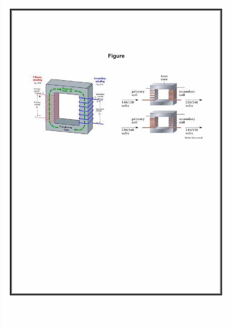
Figure
7/27/2019 Institutional Training Report EE 3rd semester
http://slidepdf.com/reader/full/institutional-training-report-ee-3rd-semester 6/14
UNIT -1
To study the transformer
1. Introduction: - A transformer is an apparatus for converting electrical power in an ac
system at one voltage or current into electrical power at some other voltage or current without
the use of rotating parts.
2. A constant-voltage transformer: - consists essentially of three parts: the primary
coil which carries the alternating current from the supply lines, the core of magnetic material
in which is produced an alternating magnetic flux, and the secondary coil in which is
generated an emf by the change of magnetism in the core which it surrounds.
3. Transformer terminology: - The primary winding is the winding of the transformer
which is connected to the source of power. It may be either the high- or the low voltage
winding, depending upon the application of the transformer.
4. Transformer cores:- Until recently, all transformer cores were made up of stacks of
sheet-steel punching firmly clamped together. One method of assembly and clamping of the
sheets is shown in Sometimes the laminations are coated with a thin varnish.

7/27/2019 Institutional Training Report EE 3rd semester
http://slidepdf.com/reader/full/institutional-training-report-ee-3rd-semester 7/14
5. Cooling of transformers:- A certain amount of the electrical energy delivered
a transformer is transformed into heat energy because of the resistance of its windings andthe
hysteresis and eddy currents in the iron core. Means must be provided for removing this heat
energy from the transformer and dissipating it into the surrounding air.
6. The oil used in transformers:- (Standard Handbook for Electrical Engineers)
performs two important functions. It serves to insulate the various coils from each other and
from the core, and it conducts the heat from the coils and core to some cooler surfaces, whereit is either dissipated in the surrounding air or transferred to some cooling medium. It is
evident that the oil should be free from any conducting material, it should be sufficiently thin
to circulate rapidly when subjected to differences of temperatures at different places, and it
should not be ignitable until its temperature has been raised to a very highis excessive. The
oil is subsequently passed through a dry-sand filter to remove any traces
7. Insulation between windings: - The great majority of transformers are constructed
with two or more windings which are electrically insulated from each other. In some cases asingle winding is employed, parts of the winding functioning as both primary and secondary.
These transformers are called autotransformers. They are frequently used when the voltage
ratio is small. Autotransformers should never be used for high voltage ratios, as the low-
voltage winding is not insulated from the high-voltage one, so that in case of trouble it would
be dangerous to both life and equipment. Refer to Sec. 32 for further discussion.

7/27/2019 Institutional Training Report EE 3rd semester
http://slidepdf.com/reader/full/institutional-training-report-ee-3rd-semester 8/14
8. Transformer insulation:- The type of insulation used in dry-type – transformer
design and construction has a definite bearing on the size and operating temperature of the
unit. Currently four classes of insulation, each having a separate NEMA specification and
temperature limit, are being used. A look at these will facilitate selection of the proper unitto
meet prescribed installation and operating conditions.
9. Transformers are built in both single- and polyphase units: - A polyphase
transformer consists of separate insulated electric windings for the different phases wound
upon a single core structure, certain portions of which are common to the different phases.
Three-Phase Transformers:- (Standard Handbook for Electrical Engineers). Although there
are numerous possible arrangements of the coils and cores in constructing a polyphase
transformer, it can be stated that a polyphase transformer generally consists of several
onephase transformers with separate electric circuits but having certain magnetic circuits in
common. A three-phase transformer is illustrated in Fig. 5.14, together with the component
one-phase transformer. It will be observed that a three-phase transformer requires 3 times as
much copper as the one-phase component transformer but less than 3 times as much iron.
Thus in comparison with three individual transformers, the three-phase unit is somewhat
lighter and more efficient. Each component transformer operates as though the others were
not present, the flux of one transformer combining with that of an adjacent transformer to
produce a resultant flux exactly equal to that of each one alone.
of a Westinghouse three-phase transformer.
10. Application of three-phase transformers:- (A. D. Fishel). For central stations
of medium size, three-phase transformers are rarely superior to single-phase, except when the
large sizes can be applied, in which case the transformers are normally installed in
substations or central stations. The chief reason for this is the no flexibility of a three-phase
Transformer. It is usually purchased for a particular size and type of load, and if service

7/27/2019 Institutional Training Report EE 3rd semester
http://slidepdf.com/reader/full/institutional-training-report-ee-3rd-semester 9/14
more than the failure of one single-phase transformer in a bank of three is of little importance
because of the comparatively few failures of modern transformers.
11. Transformer ratios: - The voltage ratio of a constant-voltage transformer, i.e.,
thecratio of primary to secondary voltage, depends primarily upon the ratio of the primary tothe secondary turns. The voltage ratio will vary slightly with the amount and power factor of
the load. For general work the voltage ratio can be taken as equal to the turn ratio of the
windings.
The current ratio of a constant-voltage transformer will be approximately equal to the inverse
ratio of the turns in the two windings. For example, for transforming or ―stepping down‖
from 2400 to 120 V the ratio of the turns in the windings will be show.
12. The regulation of a transformer:-is the change in secondary voltage from noload to full load. It is generally expressed as a percentage of the full-load secondary voltage:
The regulation depends upon the design of the transformer and the power factor of the load.
Although with a no inductive load such as incandescent lamps, the regulation of transformers
is within about 3 percent, with an inductive load the drop in voltage between no load and full
load increases to possibly about 5 percent. If the motor load is large and fluctuating and close
lamp regulation is important, it is desirable to use separate transformersfor the motors.
13. The efficiency of a transformer:- is, as with any other device, the ratio of theoutput to input or, in other words, the ratio of the output to the output plus the losses. As a
formula it can be expressed thus: Average efficiencies of transformers are given in Secs.
14. The copper loss of a transformer:- is determined by the resistances of the
hightensionand low-tension windings and of the leads. It is equal to the sum of the watts of I
2 R losses in these components at the load for which it is desired to compute the efficiency.
15. The iron loss of a transformer:- is equal to the sum of the losses in the iron core.
These losses consist of eddy- or Foucault-current losses and hysteresis losses. Eddy-current
losses are due to currents generated by the alternating flux circulating within each lamination
composing the core, and they are minimized by using thin laminations and by insulating
adjacent laminations with insulating varnish. Hysteresis losses are due to the power required
to reverse the magnetism of the iron core at each alternation and are determined by the
amount and the grade of iron used for the laminations for the core.
16. Transformer ratings: - Transformers are rated at their kilovolt-ampere (kVA)
outputs. If the load to be supplied by a transformer is at 100 percent power factor (pf), the
7/27/2019 Institutional Training Report EE 3rd semester
http://slidepdf.com/reader/full/institutional-training-report-ee-3rd-semester 10/14
kilowatt (kW) output will be the same as the kilovolt-ampere (kVA) output. If the load has a
lesser power factor, the kW output will be less than the kVA output proportionally as the
.

7/27/2019 Institutional Training Report EE 3rd semester
http://slidepdf.com/reader/full/institutional-training-report-ee-3rd-semester 11/14
To study the winding of dc machines
17. Introduction:- D.C. motors are seldom used in ordinary applications because all
electric supply companies furnish alternating current However, for special applications such
as in steel mills, mines and electric trains, it is advantageous to convert alternating current
into direct current in order to use d.c. motors. The reason is that speed/torque characteristicsof d.c. motors are much more superior to that of a.c. motors. Therefore, it is not surprising to
note that for industrial drives, d.c. motors are as popular as 3-phase induction motors. Like
d.c. generators, d.c. motors are also of three types viz., series-wound, shunt-wound and
compound wound. The use of a particular motor depends upon the mechanical load it has to
drive.
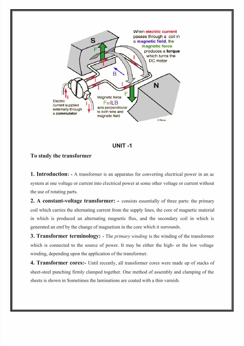
D.C. Motor Principle
A machine that converts d.c. power into mechanical power is known as a d.c.
motor. Its operation is based on the principle that when a current carrying
conductor is placed in a magnetic field, the conductor experiences a mechanical
force. The direction of this force is given by Fleming’s left hand rule andmagnitude is given by;
Basically, there is no constructional difference between a d.c. motor and a d.c.generator. The samed.c. machine can be run as a generator or motor.
Working of D.C. Motor
Consider a part of a multipolar d.c. motor as shown in Fig. (4.1). When the
terminals of the motor are connected to an external source of d.c. supply:
(i) the field magnets are excited developing alternate N and S poles;
(ii) the armature conductors carry ^currents. All conductors under N-pole
carry currents in one direction while all the conductors under S-polecarry currents in the opposite
direction.Suppose the conductors under N-pole carry currents into the plane of the paperand those

7/27/2019 Institutional Training Report EE 3rd semester
http://slidepdf.com/reader/full/institutional-training-report-ee-3rd-semester 12/14
under S-pole carry currents out of the plane of the paper as shown in . Since each armature
conductor is carrying current and is placed in the
Back or Counter E.M.F. When the armature of a d.c. motor rotates under the influence
of the driving torque, the armature conductors move through the magnetic field and hencee.m.f. is induced in them as in a generator The induced e.m.f. acts in opposite direction to the
applied voltage V(Lenz’s law) and in known as back or counter e.m.f. Eb. The back e.m.f. is
always less than the applied voltage V, although this difference is small when the motor is
running under normal conditions.
Significance of Back E.M.F.
The presence of back e.m.f. makes the d.c. motor a self-regulating machine i.e.,
it makes the motor to draw as much armature current as is just sufficient todevelop the torque required by the load.
Voltage Equation of D.C. Motor
Let in a d.c. motor
V = applied voltage
Eb = back e.m.f.
Ra = armature resistance
Ia = armature currentSince back e.m.f. Eb acts in opposition to the
applied voltage V, the net voltage across the armature circuit is V. The armature current Ia is
given by; This is known as voltage equation of the d.c. motor.
Power Equation
If Eq.(i) above is multiplied by ly throughout, we get, This is known as power equation of the
d.c. motor. VIa = electric power supplied to armature (armature input) EbIa = power
developed by armature (armature output) I R = electric power wasted in armature (armatureCu loss) Thus out of the armature input, a small portion (about 5%) is wasted as a and the
remaining portion EbIa is converted into mechanical power within the armature.
24.Limitations
In practice, we never aim at achieving maximum power due to the following
reasons:
(i) The armature current under this condition is very large — much excess of
rated current of the machine.
(ii) Half of the input power is wasted in the armature circuit. In fact, if we
7/27/2019 Institutional Training Report EE 3rd semester
http://slidepdf.com/reader/full/institutional-training-report-ee-3rd-semester 13/14
take into account other losses (iron and mechanical), the efficiency will
be well below 50%.
Types of D.C. Motors
Like generators, there are three types of d.c. motors characterized by theconnections of field winding in relation to the armature viz.:
(i) Shunt-wound motor in which the field winding is connected in parallel
(ii) with the armature [See Fig. 4.4]. The current through the shunt field
winding is not the same as the armature current. Shunt field windings are designed to produce
the necessary m.m.f. by means of a relatively large number of turns of wire having high
resistance. Therefore, shunt field current is relatively small compared with the armature
current.
(ii) Series-wound motor in which the field winding is connected in series with the armature.
Therefore, series field winding carries the armature current. Since the current passing through
a series field winding is the same as the armature current, series field windings must be
designed with much fewer turns than shunt field windings for the same m.m.f. Therefore, a
series field winding has a relatively small number of turns of thick wire and, therefore, will
possess a low resistance.
(iii) Compound-wound motor which has two field windings; one connected in
parallel with the armature and the other in series with it. There are two types of compound
motor connections (like generators). When the shunt field winding is directly connected
across the armature terminals . it is called short-shunt connection. When the shunt winding is
so
connected that it shunts the series combination of armature and series field
[See Fig. 4.7], it is called long-shunt connection.
The compound machines (generators or motors) are always designed so that the

7/27/2019 Institutional Training Report EE 3rd semester
http://slidepdf.com/reader/full/institutional-training-report-ee-3rd-semester 14/14