installation & service 101 · • components of the hfc network • advantages of the hfc...
TRANSCRIPT

Installation & Service 101Installation & Service 101

Overview

What to Learn
• CATV History
• How we receive the signals
• Components of the HFC Network
• Advantages of the HFC Network
• FTTx & Fiber Deep networks

Where It All Started
A few years after World War II, John Walson, a
Pennsylvania appliance store owner, placed an antenna on top of a local mountain and ran a cable down to his store and to a few of his customers’homes. By doing this, he created North America’s first CATV – Community Antenna Television.

Where We Get the Signals
• Over-the-Air
Broadcasts
• Local Feed
• Microwave
• Satellite
The Hybrid Fiber Coax Network• This system replaces the trunk lines and
amplifiers of the Tree and Branch Network with fiber optic cables and optical receivers
• The HFC system makes two directional signal flow possible which allows us to provide our customers with digital video, high-speed internet, and digital telephone services.

Fiber Components
Power Supply
Enclosure
Node
Snowshoe
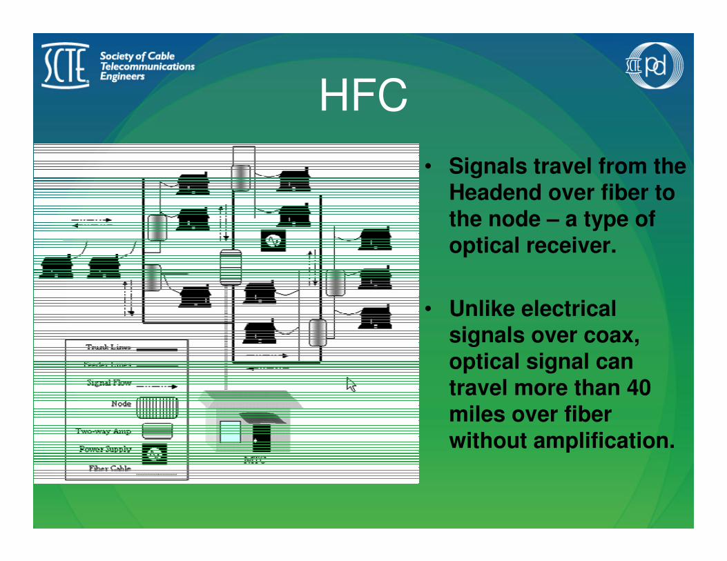
HFC
• Signals travel from the Headend over fiber to the node – a type of optical receiver.
• Unlike electrical signals over coax, optical signal can travel more than 40 miles over fiber without amplification.

The Node
• The node acts as a
translator – it converts
optical energy into electrical
energy in the downstream
direction and electrical
energy into optical energy in
the upstream direction.

Redundancy• One way to increase
security and reliability in the HFC network is to create a redundant ring, sometimes called ring-in-ring architecture.
• A redundant ring can ensure uninterrupted service to all customers if there is a break in the fiber.

Fiber Deep

FTTH
Fiber To The Home – Fiber optic
network extends all the way to the
side of the home. It still converts
from Fiber to Coax at the NIU
location.

Passive &
Active DevicesBasic Electrical Concepts in Cable

• Active Device: Anything that requires electricity in order to operate.
Node – Line Extender – House Amp
• Passive Device: Anything that does not require electricity in order to operate.
Tap – Directional Coupler – Splitter

Drop Amplifier Overview
• Common Drop Amplifier configurations:
– Single output, 15 dB gain
– Two output, 11 dB effective gain
– Four output, 7 dB effective gain
– Eight output, 4 dB effective gain
• Do Not use to compensate for a cable
fault. Input range: 3 – 8 dBmV

Drop Amplifier
Single Output
+15 dB
Return Path Loss = MinimalForward Gain = 15 dB

Drop Amplifier
Without Power Inserter
DC Input
RF Input
RF
OU
T
/DC
IN
7.5dB
7.5dB1
7.5dB2
7.5dB3
SUBSCRIBER
AMPLIFER
AC ADAPTER
– +

Drop Power Inserter
•Inserts power onto the drop to power the drop
amplifier . . .

Drop Amplifier
With Power Inserter
DC Input
RF Input
RF
OU
T
/DC
IN
7.5dB
7.5dB1
7.5dB2
7.5dB3
SUBSCRIBER
AMPLIFER
IN TV
POWERIN
AC ADAPTER
– +
DC Power
RF Signal
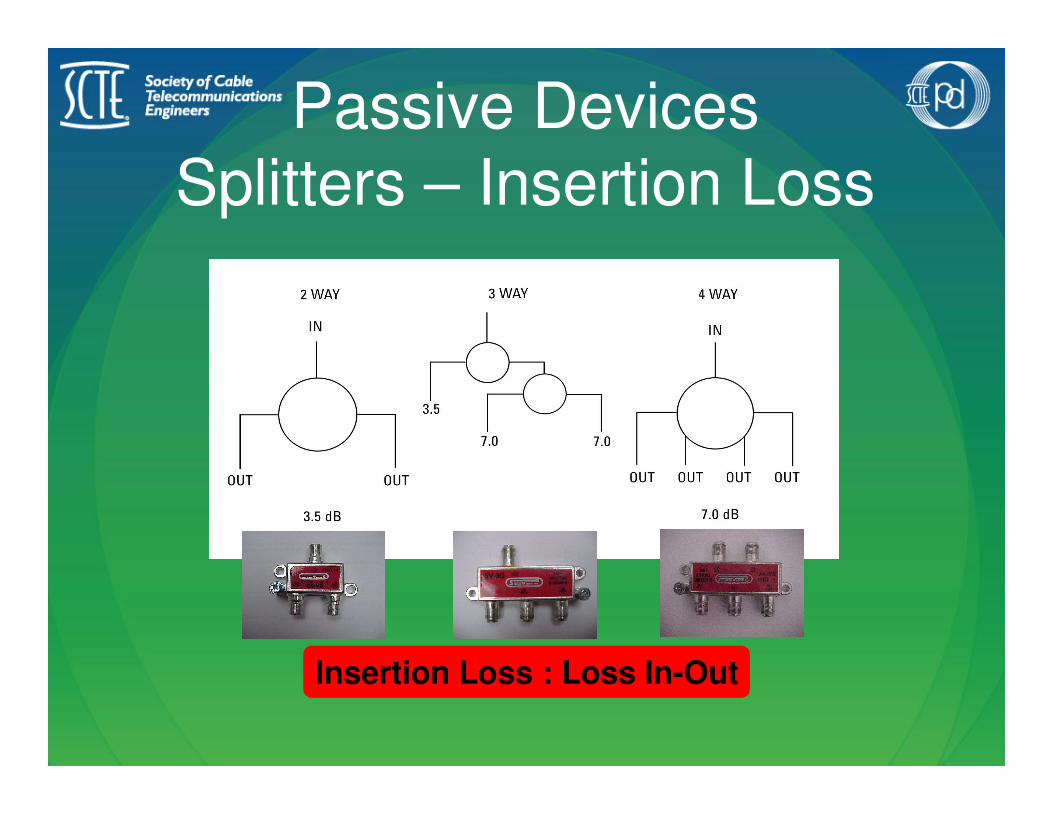
Passive Devices
Splitters – Insertion Loss
Insertion Loss : Loss In-Out
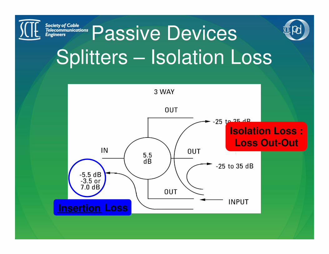
Passive Devices
Splitters – Isolation Loss
Isolation Loss :Loss Out-Out
________ LossInsertion

Backwards Splitter

Passive Devices
Directional Couplers – Tap
Loss
Tap Loss : Loss In-Tap

Passive Devices
DC – Isolation Loss
Isolation Loss :Loss Tap-Out
Insertion Loss :Loss In-Out
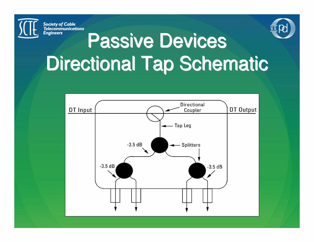
Passive Devices
Directional Tap Schematic
Passive Devices
Directional Tap Schematic

Passive Devices
DT – Insertion Loss
Passive Devices
DT – Insertion Loss

Passive Devices
DT – Isolation Loss
Passive Devices
DT – Isolation Loss
Isolation Loss :Tap port-Tap port
& Tap port-Out

Passive Devices
DT – Tap Loss
Passive Devices
DT – Tap Loss

DT Plant Design

30
The Aerial
DropConnecting the House to the Plant

Designing the Drop
• Drop Components
– The Tap
– The Drop
– The Demarc
• Where to Locate the Drop
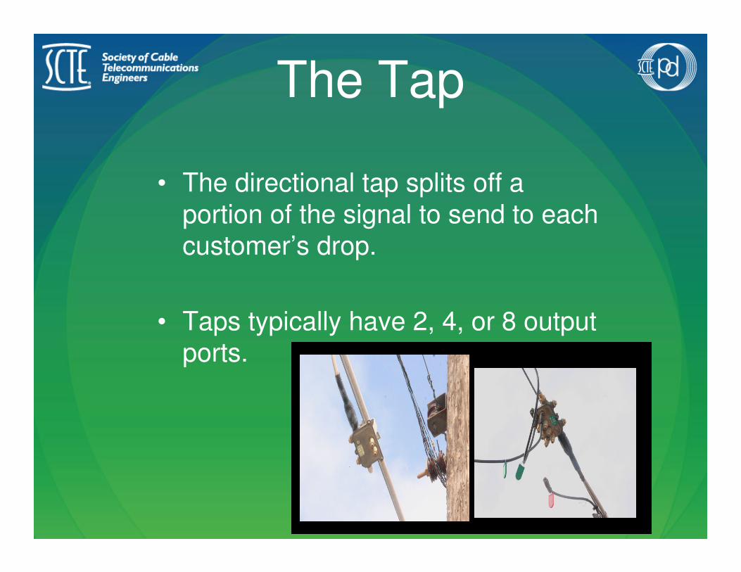
The Tap
• The directional tap splits off a
portion of the signal to send to each
customer’s drop.
• Taps typically have 2, 4, or 8 output
ports.

Hardware at the Tap
Directional Tap
Span Clamp
J-Hook
ID
Tags
Locking Terminators

Hardware for the Drop
RG6 Fitting RG59 Fitting
Grommet Silicon Grease
Zip Tie

Hardware for the Demarc
Grounding Splitters Ground Blocks
Grounding Hardware P-Hook

Design Factors to
Consider• Trespass
• Clearance
• Other Utilities
• Plants/Trees
• Storage Buildings
• Outlet Location
• Grounding
• Swimming Pools
• Appearance
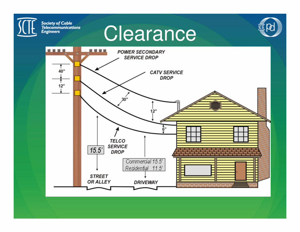
Clearance

Spacing at the Tap
• Climbing SpaceMaintain 30” climbing space
for all utility technicians.
• Distance from PoleSpan clamps must be at
least 24” from pole center.
•
Maintain
30”
Climbing
Space
at the Pole
Span Clamps
Must Be at Least
24”From Pole
Center

Mid-Span• Uses:
• to avoid obstructions
• to maintain proper clearances
• to avoid crossing other utility lines
• to avoid property trespass
• Always use two span clamps when running a mid-span drop.
• The mid-span requires four 3-3-5 wraps:
– One at the tap
– Two at “mid” span
– One at the house
Start your mid-span at the tap.Never start at the house!

Trespass
Always use
a mid-span
drop to
avoid
crossing
property
lines

A J-Hook can be used to gain extra height
or to clear an obstruction.
• Hammer the J-Hook into the utility pole until 1
1/2” is exposed – there should be no thread showing.
• Be careful not to obstruct the 30” climbing space.
• Always attach loose cable to the utility pole using
clips or staples.
• Never use a P-Hook in place of a J-Hook
J-Hook
Installing
the
Drop
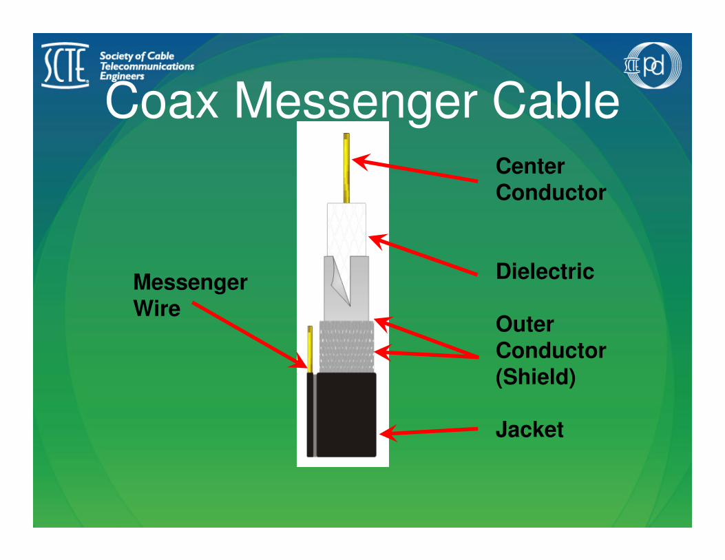
Coax Messenger CableCenter Conductor
Dielectric
Outer Conductor (Shield)
Jacket
Messenger Wire

Installing F-Connectors
Make sure dielectric is flush with base of fitting before compressing.
Make sure there is no dielectric or braid clinging to the center conductor.
Do not scrape center conductor with any metal objects.
Leave stinger 1/16” to 1/8”beyond the end of the fitting –do not cut flush.

Weatherproofing• Use a grommet and silicone grease on
every outdoor connection.
• Make drip loops and service loops.
No grease should touch the
center conductor or the
dielectric.

Steps for Mid-Span
Attachment1. Cut the messenger wire – be
careful not to cut into the jacket.
2. Peel back messenger wire in both directions.
3. Starting with tap end, install
drop hanger and place on the
span clamp.
4. Roll up a service loop with a 4-
6” diameter.
5. Place zip ties on the service loop at 10, 2, and 6 o’clock.
6. Install another drop hanger on the house end.
Connect to Tap
Connect Mid-Span
Connect to House

Avoiding “the Bite”Cable TV Installer Killed After Falling 21’
From a Ladder
The victim had not reset the ladder and was
not wearing fall protection as required by the
company. The co-worker started to tell him to
put on the safety belt when the victim cut the
cable leading away from the junction box. As
the tension from the cable was released, the
main cable and strand swung backwards,
whipping the ladder attached to it. Although
the ladder did not come off the strand, the
movement threw the victim off the ladder to
the asphalt road. The co-worker ran to the
house and called the police who responded
with the first aid squad. The victim was
transported to the local hospital where he
was pronounced dead.

Proper SlackTwo considerations for proper drop slack:
•Six inches of slack for every 50 feet of drop – even with a mid-span
•Try to keep drop parallel with other utility drops
50’
6”

Attachment to the House
The P-Hook should attach through the fascia board
into the supporting stud.
This supporting stud can be located by finding the nails
that hold the fascia board in
place.
No threads should show.
The tail of the P-Hook
should point to the ground.
Never use a J-Hook in place of a P-Hook.

Evaluating
an
ExistingDrop
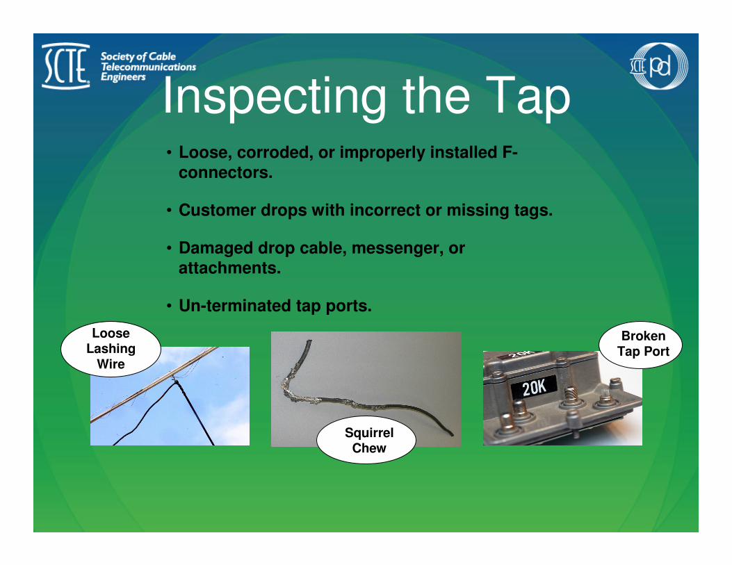
Inspecting the Tap
Broken Tap Port
Squirrel Chew
Loose Lashing
Wire
• Loose, corroded, or improperly installed F-
connectors.
• Customer drops with incorrect or missing tags.
• Damaged drop cable, messenger, or
attachments.
• Un-terminated tap ports.

Checking Signal LevelIn order to save troubleshooting time and to prevent unnecessary trips up the ladder, always check signal level in three places on every job:
•The Tap•The Demarc•The Outlet
Low, middle, and high analog
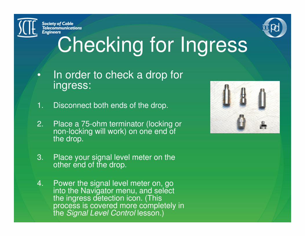
Checking for Ingress
• In order to check a drop for ingress:
1. Disconnect both ends of the drop.
2. Place a 75-ohm terminator (locking or non-locking will work) on one end of the drop.
3. Place your signal level meter on the other end of the drop.
4. Power the signal level meter on, go into the Navigator menu, and select the ingress detection icon. (This process is covered more completely in the Signal Level Control lesson.)

Upgrading the DemarcReplace all painted or
corroded splitters, ground
blocks, fittings, and
grounding hardware.
Replace any
aftermarket splitters
with company-issued
splitters that
accommodate 5-
1000mHz.
Make sure that all
grounding hardware is
shiny – replace any old or
corroded hardware.

Grounding

- Grounding -
The National Electric Code
The NEC provides a set of standards for
the electrical and communications wiring
in homes.
The basic NEC requirement is for a common ground.• We accomplish this by bonding together our serviceat the power ground location.

Purpose of a Ground• Protects people from electric shock.
• Protects equipment from damage
caused by a surge of electricity.
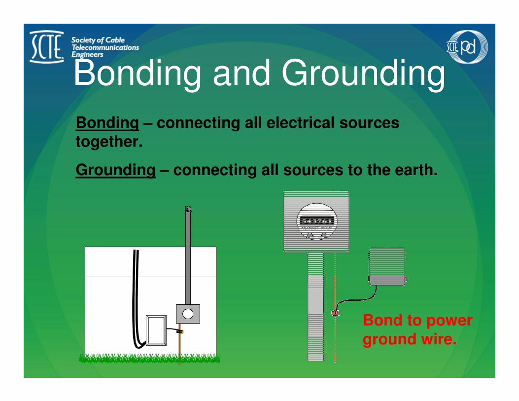
Bonding and Grounding
Bonding – connecting all electrical sources together.
Grounding – connecting all sources to the earth.
Bond to power ground wire.

Grounding
Use #12 wire – do not use messenger wire!
Ground wire should not exceed 10’ or the distance to the nearest outlet –whichever is shorter.
The key to a good ground is co-bonding with the existing power ground.
Replace any corroded connections.
Splitters/ground blocks must be mounted horizontally (left and right).

Hazards of Improper
Grounding
Signal
Levels

Signal Levels
• Identify the unit measuring signal strength.
• List the factors that effect signal strength.
• Calculate cable loss.

The Decibel-Millivolt• dBmV is the standard unit to measure
signal strength.
• It was derived from Alexander Graham Bell’s experiments of sound intensity.
• 0dBmV = 1 mV across 75 Ω
4 mV+12 dBmV
2 mV+6 dBmV
1 mV0 dBmV
.5 mV-6 dBmV
.25 mV-12 dBmV
Voltage EquivalentSignal Level
Reference
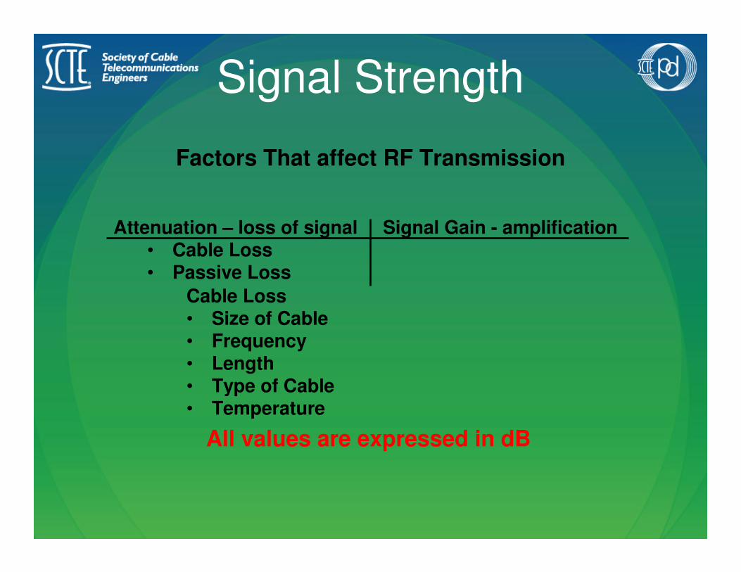
Signal Strength
Factors That affect RF Transmission
Attenuation – loss of signal Signal Gain - amplification• Cable Loss• Passive Loss
Cable Loss• Size of Cable• Frequency• Length• Type of Cable• Temperature
All values are expressed in dB

Cable Loss
Size of Cable• Drop cables are identified by RG (radio grade)
• Plant distribution cables are identified by their diameter in decimal inches.
Frequency• Commonly measured in MHz• “Skin Effect”

Cable Loss (cont.)Length
• All cable loss charts are shown in dB / 100 ft.
Type of Cable• This corresponds to the manufacturer and
the application.
Temperature
• The higher the temperature the more cable attenuation.
• For all practical purpose, we can ignore this effect in the drop system.

Cable Loss Calculations
7.526.975.955.104.451.951.510.86RG-59
6.105.654.904.153.551.531.190.58RG-6
3.983.653.042.602.250.920.740.38RG-11
865
MHz
750
MHz
550
MHz
400
MHz
300
MHz50 MHz32 MHz5 MHz
Cable
Size
Values in dB / 100 ft
Example:
100 ft of RG-6 has 5.65 dB of attenuation at 750 MHz
The same cable will attenuate 0.58 dB at 5 MHz.
What is the loss of 250 ft of RG-6 at 865 MHz?
The formula for calculating cable loss:
footage XdB of Loss
100 ft
x250 ft
1
6.10 dB
100 ft= 15.25 dB
Signifies loss

Signal TransmissionSignal Transmission
Signal Transmission
• Define tilt.
• Identify coaxial cable impedance.
• List causes of impedance mismatch.
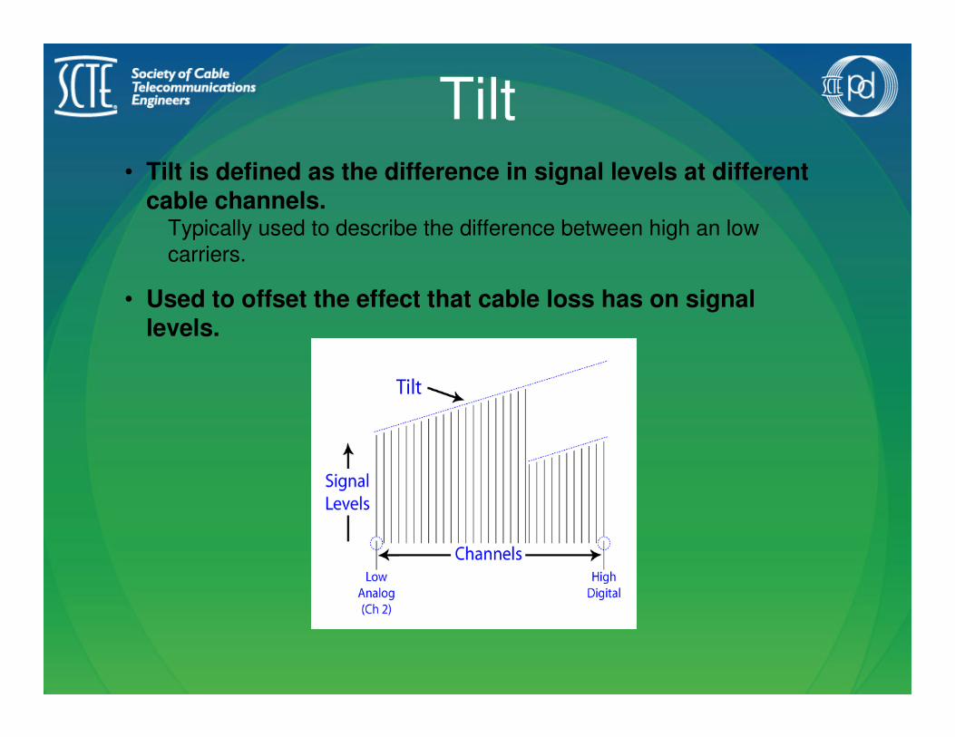
Tilt• Tilt is defined as the difference in signal levels at different
cable channels.Typically used to describe the difference between high an low
carriers.
• Used to offset the effect that cable loss has on signal levels.

Signal Distribution
• As signals travel down the distribution lines, the higher channels will eventually have lower signal levels than the lower channels.
Think back to our discussion on “skin effect”.
• This is why you will see different tap values in the CATV plant.
The closer a tap is to an amplifier, the higher the tap value.

Cable ImpedanceCable Impedance
Impedance is the apparent RF resistance between the center conductor and the outer conductor.
Changing the characteristic impedance can affect the cables’ transmission quality.
The characteristic impedance is 75 ΩΩΩΩ

Impedance FactorsImpedance Factors
3 Factors that determine cable impedance
• Ratio of the center conductor to outer conductor
• Distance from the center conductor to outer conductor
• Type of dielectric material used

Group ActivityGroup Activity
List some things that can cause the cable impedance to change.
List some things you can do to prevent impedance mismatch.(a loss of signal energy do to a change in the cables’impedance)

FrequencyFrequency
Frequency
• Identify commonly used term for frequency.
• Define modulation.
• Identify forward and return channel allocations.
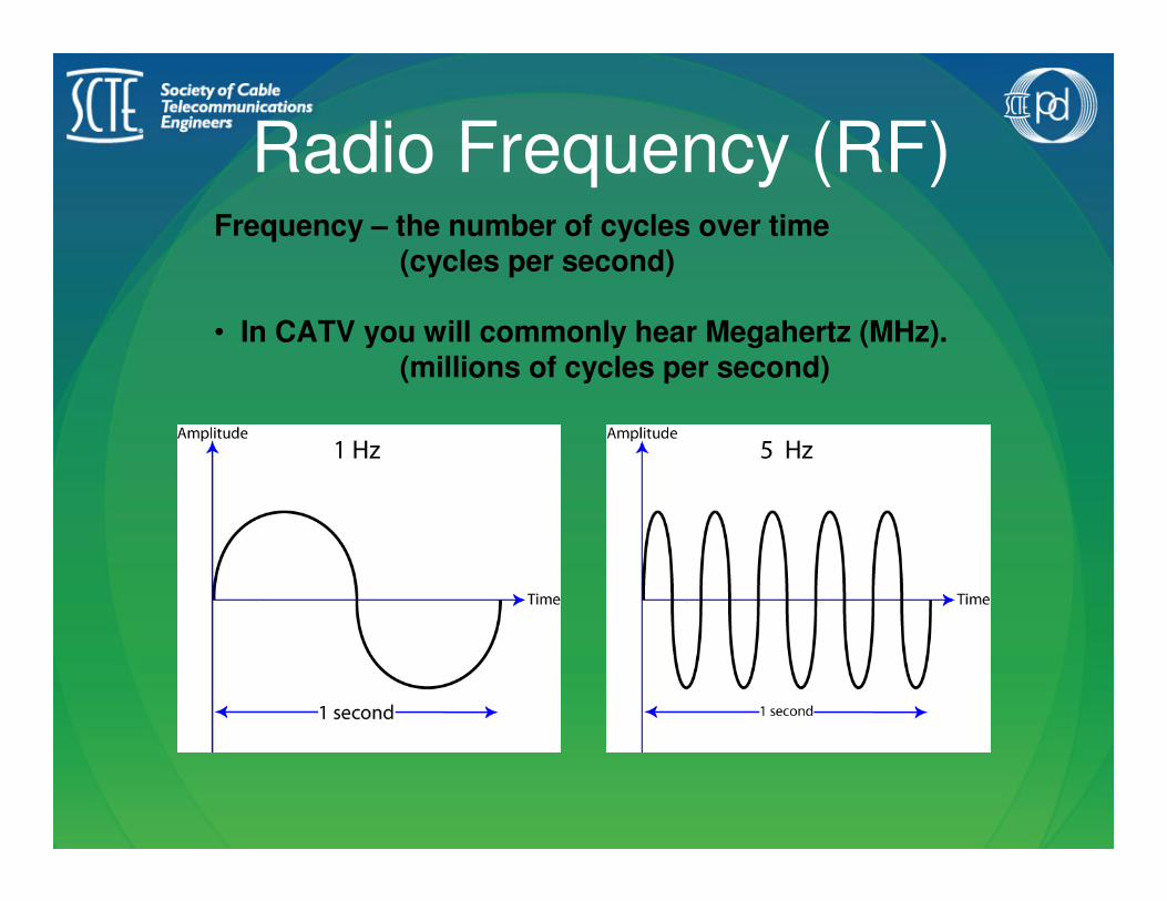
Radio Frequency (RF)Frequency – the number of cycles over time
(cycles per second)
• In CATV you will commonly hear Megahertz (MHz).(millions of cycles per second)

TV Channels
Modulation – placing intelligent information onto a radio frequency (RF) carrier wave
• The information is allocated a 6 MHz space called a channel.

Channel Allocation
Typical System Channel AllocationOff-Air Allocation

Signal
Level
Meter

Signal Level Meter
• State the purpose of a Signal Level Meter.
• Maintain your SLM.
• Measure signal levels on the cable plant.
Signal Level Meter (SLM)
A SLM is basically a frequency tuned
voltmeter.
The main uses for a Tech are:• Measure cable signals
• Locate non-CATV signals on the cable line.

Preventative MaintenanceThe “key” to accurate measurements
and long time usage of any meter is
proper care and maintenance.
Change jumpers regularly
Replace all F-81’s frequently
Calibrate noise floor once a month or if dropped
Protect from the elements
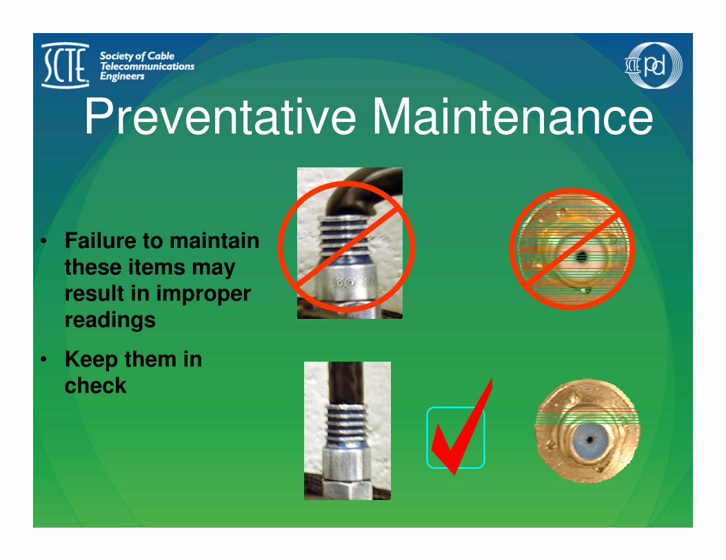
Preventative Maintenance
• Failure to maintain these items may result in improper readings
• Keep them in check

Preventative MaintenanceProtect meter from extreme moisture.
Do not expose LCD to direct sunlight for prolonged periods.
Keep LCD from freezing, store inside when not in use.

Signal Signal
LeakageLeakage

Signal Leakage
• Explain how signal leakage can occur.
• Define egress and ingress.
• State the FCC Rules for signal leakage.
• Identify common sources of signal leakage.
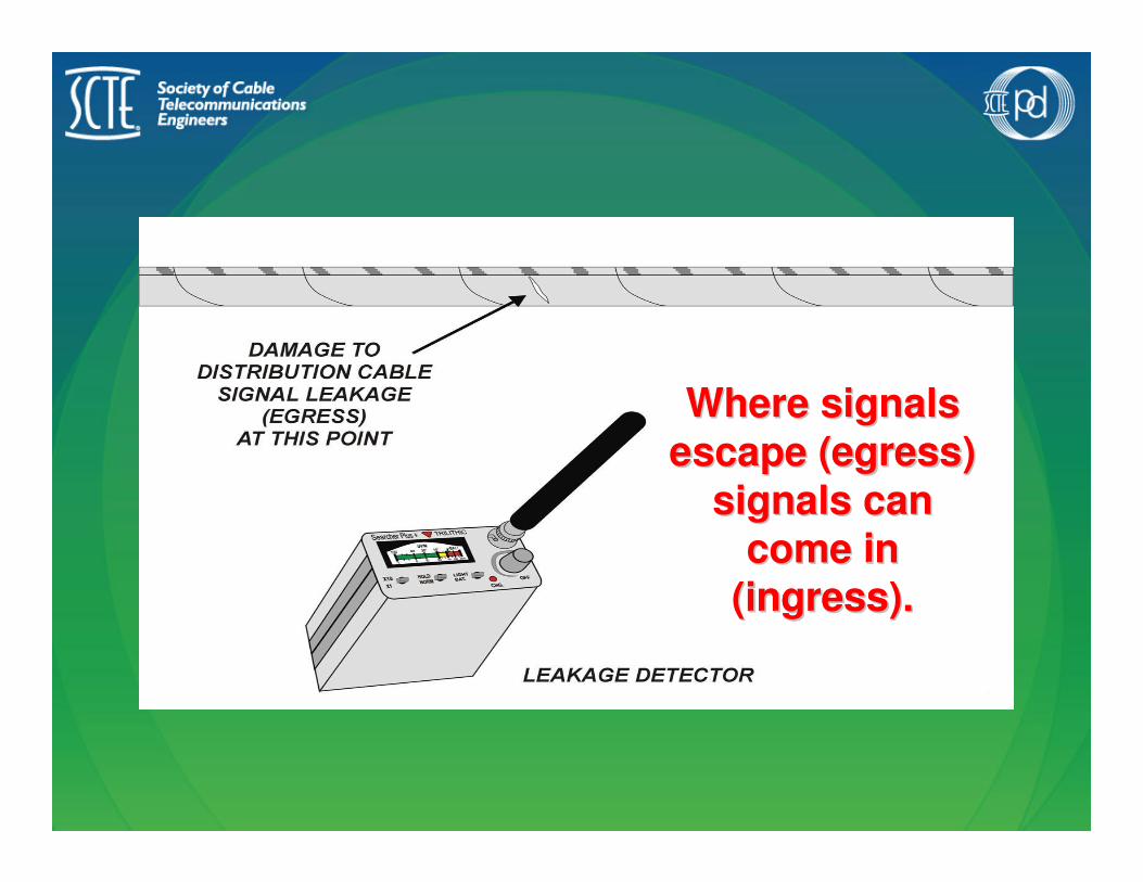
Where signals Where signals
escape (egress) escape (egress)
signals can signals can
come in come in
(ingress).(ingress).
ee
ii
egressegress
ingressingress

The Federal Communications Commission
govern the maximum strength of signals
that can be leaked from the cable system.
The amount of leakage that is measured
and repaired within a CATV system is
known as Cumulative Leakage Index (CLI).
If signal leakage is left unchecked the leak
can interfere with other operating
frequencies, including the aeronautical
band.
The FCC

Common Causes• Animal chews
• Poor quality cable/construction
• Customer installs
• Un-terminated tap ports
• Poorly installed connectors
• Signal Theft
90% of all signal leakage occurs in the cable drop 90% of all signal leakage occurs in the cable drop
and/or its related fittings.and/or its related fittings.
75% of all service calls are signal leakage related.75% of all service calls are signal leakage related.
Troubleshooting
Video ProblemsDivide and Conquer!
Steps for Troubleshooting
1. Analyze
2. Isolate
3. Fix
4. Verify
• Remember the basics.
• Always know what you expect your signal levels should be before you measure them.
Know how the system
works
Know how the system
works
Distinguish the symptoms1. Interview the customer
• How many TV’s?
• Is problem on all TV’s?
• How many outlets?
• When did problem start?
• What other symptoms have they noticed?
• Any recent work on house or yard?
• Is data/phone service having problems?
2. Verify symptoms• Verify picture, color and sound on all channels
• Verify local ingress channels
• Check that all digital services are available
Verify Everything
• Check signal levels at:
– Tap
– Demarc
– Outlet
• Check for quality components
– Jumpers
– Fittings
– 5-1000 MHz Splitters
– RG6 Cable

Verify Everything
• Check for leakage
• Verify proper splitter configuration
• Verify proper grounding and demarc layout

Signal
Level
Issues

Possible Signal Level Issues
• Signal level too low
• Signal level too high
• Improper frequency response
• Outages
Symptoms of Low Signal
Level• Analog Channels:• Snowy picture
• Digital Channels:• Tiling
• Freeze Frame
• No Picture/Temporarily Off Air

Signal Level Too Low
• Verify signals at tap
• Verify appropriate attenuation through drops and
passive devices
• Verify proper splitter configuration
Signal Level Too High
• Check for unnecessary amp
• Line issue
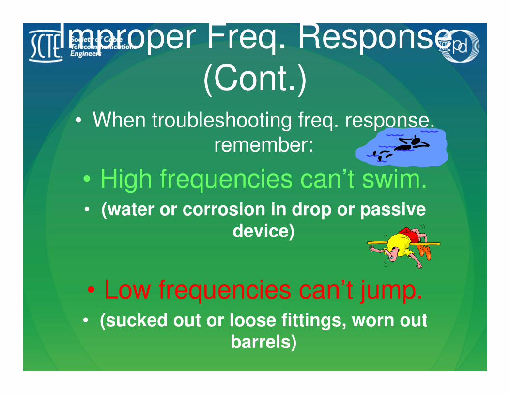
Improper Freq. Response
(Cont.)• When troubleshooting freq. response,
remember:
• High frequencies can’t swim.• (water or corrosion in drop or passive
device)
• Low frequencies can’t jump.• (sucked out or loose fittings, worn out
barrels)
Outages• If you suspect on outage, check signal levels at
the tap first and work back toward the outlet.
• If outage exists at tap, consult supervisor for
maintenance workstart. (Remember to check
multiple tap ports.)
• If outage exists only at demarc and outlet,
troubleshoot the drop and demarc.
• If outage exists only at the outlet, troubleshoot
from the demarc to the outlet.

Ingress
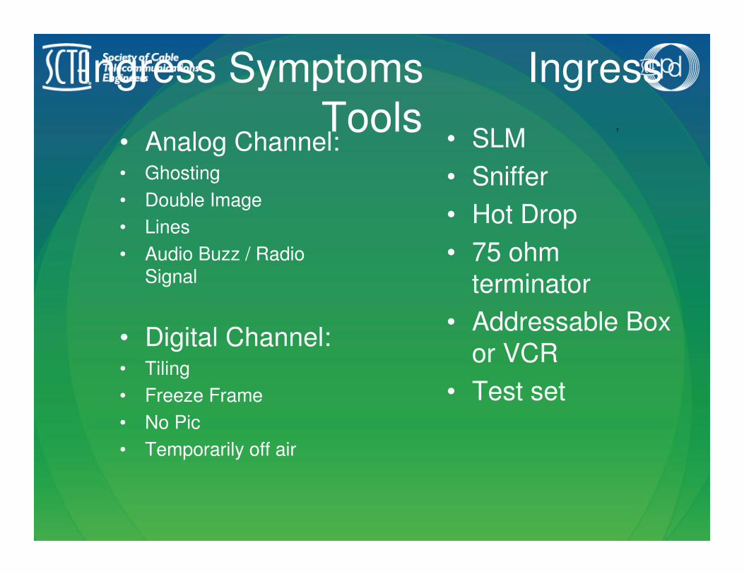
Ingress Symptoms Ingress
Tools• Analog Channel:• Ghosting
• Double Image
• Lines
• Audio Buzz / Radio Signal
• Digital Channel:• Tiling
• Freeze Frame
• No Pic
• Temporarily off air
T
• SLM
• Sniffer
• Hot Drop
• 75 ohm
terminator
• Addressable Box
or VCR
• Test set

Ingress Causes
• Damaged cable
• Bad fitting
• Loose fitting
• Push-on jumpers
• Damaged CPE
• Customer theft devices
• Damaged tap
• Damaged network
• Leakage in vicinity

Ingress Troubleshooting• The key to ingress repair is isolating the
problem.
• Quickly look the system over for obvious problems – push on jumpers, loose fittings, animal chew. Check for Leakage!
• If there is no obvious problem, use a hot drop or an SLM to isolate the problem.– Tap to TV
– Tap to demarc
– Demarc to TV

Ingress Troubleshooting• If you suspect ingress from the television:
• Place a non-locking 75 ohm terminator on the TV’s
cable input – if you have color, picture, or sound on any
local ingress channel, the TV has direct ingress.
• Disconnect the television and place a test set in its place – if the ingress disappears, the customer’s TV has
direct ingress.
• To detect ingress on Digital Channels:• Check the box’s diagnostic menu.

Common Digital Box Problems
• Yes/No on hit (usually a return path issue)• High pass filter on line – (upgrades or failed self-
installs)
• Pulled out or loose fitting
• Defective passive device
• No Data/Guide Problems (usually signal level issue)
• Check signal levels.
• Check diagnostic menu
(See DCT manual for specific errors)
•

Common Digital Box
Problems• Tiling/Freeze Frame/No Picture/Temporarily Off
Air
• Low signal level
• Low SNR
• Ingress
• Missing Channels/Premiums
• Low signal level
• Low SNR Ingress
• Back Office issue (Call dispatch.)