installation, operation & h maintenance instructions i
TRANSCRIPT
UM
IF
ID
ED
IIC
AT
ON
&
HAT
RY
E R
EC
OVE
I N TAL L T I , OPERA ION & S A ON TMA IN ENANC NS TRU T IONST E I C
HEAT
PES
PI
QA/IOM/47 Issue 3 - Heat pipes

Contents: Page
1. General introduction 1
2. Safety Issues 2
3. Installation 3
3.1 General 3
3.2 Enhanced Dehumidification Units 3
3.2.1 Horseshoe Unit 3
3.2.2 Heat pipe/ Cooling Coil ‘Combi’ Unit 4
3.3 Heat or Coolth Recovery 5
3.3.1 Horizontal Heat Recovery 5
3.3.2 Vertical Heat Recovery 5
4. Operation 6
4.1 Enhanced Dehumidification 6
4.1.1 Horseshoe/ ‘Combi’ Unit 6
4.2 Heat or Coolth Recovery 6
4.2.1 Horizontal Heat Recovery 6
4.2.2 Vertical Heat Recovery 6
5. Maintenance 6
5.1 Maintenance Schedule 7
5.2 Recovery 7
5.3 Corrective Maintenance 8
5.4 Spares List 8
QA/IOM/47 Issue 3 - Heat pipes

1. GENERAL INTRODUCTION
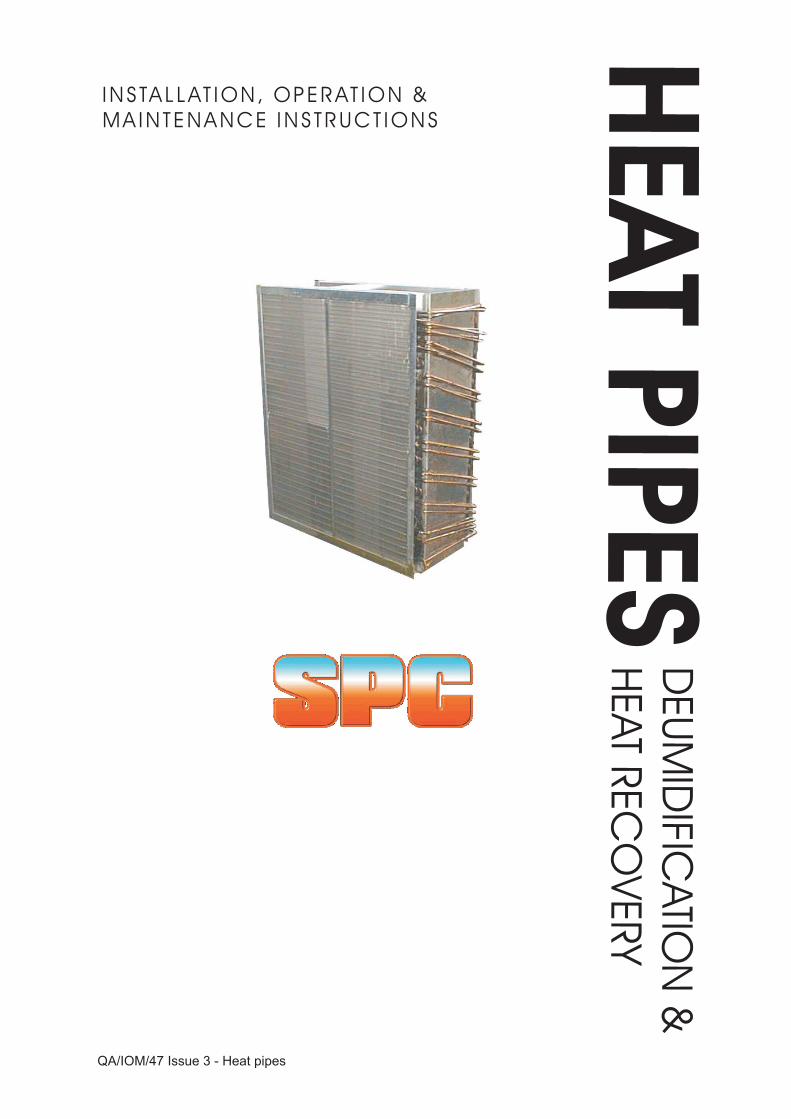
Heat pipe installations are generally used in either AHU or duct mounted applications. In the form in which they are manufactured by SPC, they have a similar construction to conventional heat exchanger coils, and the majority of installation and maintenance issues are identical to those for coils.
Operational aspects of heat pipe applications are different from normal heat exchangers, and are briefly outlined below.
An individual heat pipe is an evacuated tube, charged with a working fluid designed to operate across the range of temperatures of interest. A temperature difference from one end to the other causes evaporation of the fluid, taking with it a quantity of latent heat.
The fluid condenses at a cooler portion of the heat pipe, giving up the latent heat. The condensed fluid is returned from whence it came under gravity.
SPC manufacture heat pipe assemblies with multiple tube, serpentine, gravitationally driven heat pipes. The assemblies are designed to operate in the following applications:
a) Enhanced DehumidificationHorseshoe unit: wrap-around heat pipe (HP) assemblyCombi unit: wraparound HP assembly + cooling coil
b) Heat or coolth RecoveryHorizontal: side by side ductsVertical: straddled airflows, one over the other.
The heat pipe coils comprise one or more matrices of copper tubes supported in tube end plates and associated casing work. The tube matrix carries thin continuous fins, regularly spaced, at right angles to the tube matrix.
The fin arrays are designed to provide an enlarged airside surface and to optimise heat transfer for the design air conditions, whilst minimising the resultant airside pressure drop.
Should a chilled water cooling coil be included in a Combi type Heat pipe then the cooling coil tubes are fed via a flow header which distributes the fluid into a series of circuits designed to provide optimum in-tube fluid velocity.
In this case a return header and connection collect the fluid after it has passed through the coil. If the cooling coil uses refrigerant i.e. a DX evaporator then the inlet to the coil is via a distributor assembly and capillary tubes to ensure proper liquid distribution.
All coil blocks are tested to 22-bar air under water unless otherwise agreed. Heat pipe blocks are subsequently vacuum tested and charged with a working fluid and leak tested. DX coils are evacuated to remove any moisture prior to being sealed and filled with a holding charge of nitrogen.
Page 3QA/IOM/47 Issue 3 - Heat pipes

2. SAFETY ISSUES
If work is to be carried out on site, before any operational or maintenance work is undertaken, the plant must be in a safe state for work to proceed, and all operations must therefore be covered by local working regulations.
The Health and Safety at Work Act places a duty upon employers to provide such information, instruction, training and supervision as is necessary to ensure, as far as is reasonably practicable, the health and safety at work of their employees.
The Act also places a duty upon every employee to co-operate with his employer on matters affecting health and safety and to take reasonable care for the health and safety of himself and others who may be affected by his acts or omissions at work.
All instructions and procedures should comply with all site Health and Safety standards and conform to the following:
! Management of Health and Safety at Work (1992)
! Health and Safety at Work Act (1974)
! The Site Licence
! The Factories Act
! Health and Safety Regulations
! I.E.E. Regulations (16th Edition)
! Electricity at Work Regulations (1989)
Warnings
Before commencing work, obtain, read and ensure you understand the relevant safety documentation.
Prior to commencing maintenance work, ensure that all electrical supplies are isolated and cannot be switched on by others. Where the maintenance work or test sequence necessitates live operation, particular care must be exercised.
Wear a safety harness when working in areas above ground where no handrails or similar safety provisions apply.
Warning notices are to be prominently displayed in the vicinity of operations whenmaintenance work is in progress. They should be displayed at other locations where inadvertent operation of equipment will place maintenance staff at risk.
Page 4QA/IOM/47 Issue 3 - Heat pipes

3. INSTALLATION
3.1. GENERAL
During installation, lift heat pipe assemblies by holding the casing and not headers or connections. Larger coils may have specific provision for eyebolts or similar lifting arrangements.
Casework should be securely fixed prior to pipework flanges being made up.
3.2. ENHANCED DEHUMIDIFICATION UNITS
3.2.1. HORSESHOE UNIT
The assembly consists of 2 heat exchanger coil blocks mounted within a single sheet metal framework for ease of installation, either in retrofit or new build.
The assembly is U-shaped, with identically sized front and rear coil blocks, which constitute precool and reheat sections of the heat pipe assembly respectively. The separation between the coil blocks is sufficient to provide clearance on either side of the cooling coil, and is handed to suit the installation.
Normally baffle pieces to ensure sealing of the duct will be provisioned for by either installer or supplier, although it is the installer's responsibility to ensure that sealing is carried out correctly.
The heat pipe sections have interconnecting pipework linking them together on the opposite side of the coil from the cooling coil connections. These are encased in a rigid box to provide stiffness and to protect the pipework during installation.
The units are entirely passive, and no supply or return pipework is required for installation and operation.
Bolting up of the framework should be carried out as required to ensure support and sealing.
Sealing with mastic or similar to suit the application is the responsibility of the installer.
Condensate drainage provision is the responsibility of the installer.
Retrofit: Access through the AHU casing for installation of the assembly around the cooling coil should be from the opposite end to the cooling coil connections. The Horseshoe Unit is introduced around the cooling coil. Upon installation the contractor must ensure no air bypass within the cabinet, and proper sealing and insulation to make good the installation.
New: The dimensions of the AHU must provide for inclusion of the Horseshoe Unit interconnecting pipework section around the cooling coil. Upon installation the manufacturer must ensure no air bypass within the cabinet, and proper sealing and insulation to make good the installation
Page 5QA/IOM/47 Issue 3 - Heat pipes

3.2.2 HEAT PIPE/ COOLING COIL 'COMBI' UNIT
The assembly consists of 3 heat exchanger coil blocks mounted within a single sheet metal framework for ease of installation.
The central block comprises the cooling coil, designed for operation with either refrigerant or chilled water according to specification. The cooling coil has connections that are handed to suit the installation.
The cooling coil block resides between the front and rear heat pipe blocks, which constitute precool and reheat sections of the heat pipe assembly respectively.
The heat pipe sections have interconnecting pipework linking them together on the opposite side of the assembly from the cooling coil connections.
Bolting up of the framework should be carried out as required to ensure support and sealing.
Sealing with mastic or similar to suit the application is the responsibility of the installer.
Condensate drainage provision is the responsibility of the installer.
Retrofit: It is the responsibility of the installer to ensure that there is adequate room for installation of the assembly. Existing cooling equipment should be removed, making good as required. The Combi Unit can then be introduced in place of the original cooling coil. Upon installation the contractor must ensure no air bypass occurs within the AHU, and that proper sealing is carried out to make good the installation.
New: The dimensions of the AHU shall provision for inclusion of the Combi Unit. Upon installation the manufacturer must ensure no air bypass within the cabinet, and proper sealing and insulation to make good the installation
Water Coils: Water flow is into the bottom connection and returns from the top, thus assisting in the venting of the system. The coils are handed and should be connected in counter flow i.e. the water flow connection is at the leaving airside of the coil; the return water flow to the entering air side of the coil.
When making screwed connections for the coil, hold the header connection with grips or similar. The copper coil tubes may be bent or fractured if excessive strain is put on the headers.
Pipe flanges need bolt holes exactly aligned with those on coil flanges if supplied. Supply and return pipework should have adequate flexibility and support to avoid straining the coil.
Adequate provision shall be made for venting and draining of the cooling coil. Sockets for air venting are at the high point in the circuit to assist with air removal during set-up.
Drain plugs are located at low points to assist with drainage if coil removal is necessary. Otherwise all water coils should be capable of venting and draining through connecting pipework.
Page 6QA/IOM/47 Issue 3 - Heat pipes

Refrigerant coils: Evaporator coils are supplied with one or more liquid refrigerant distributors connected via capillary tubes to the coil circuitry. These are of equal length for correct refrigerant distribution. Care should be taken to avoid kinking the tubes.
Refrigerant coils are generally supplied with sealed caps, and the coil positively charged with dry nitrogen. The connections should be cut or sweated off when ready for installation. Capillary or compression fittings should be fitted according to manufacturer's instructions. The handing convention used by SPC results in the outlet being at the lowest position on the suction header.
3.3 . HEAT OR COOLTH RECOVERY
3.3.1. HORIZONTAL HEAT RECOVERY: side by side ducts
The assembly consists of two coil blocks of the same height and which may or may not be the same length or fin density. Care should therefore be exercised in ensuring that the unit is correctly handed during installation.
The blocks are adjacent to each other, and separated by a central divider.Airflow across the two blocks should be in counterflow for optimal heat transfer. Heat will be transferred from side to side in the direction of decreasing air temperature.
Care must be taken to ensure that the unit is installed in the correct orientation. Heatpipes will be marked 'TOP' and 'BOTTOM' and 'SUPPLY' and 'EXHAUST'. Drainpan and eliminator sections may be incorporated on one or both sides if latent cooling, condensation and carryover are anticipated.
The units are entirely passive, and no supply or return pipework is required for installation and operation.
Bolting up of the framework should be carried out as required to ensure support and sealing. Sealing with mastic or similar to suit the application is the responsibility of the installer. Condensate drainage provision is also the responsibility of the installer.
3.3.2. VERTICAL HEAT RECOVERY: piggyback airflows The assembly consists of two heat pipe blocks of the same width and which may or may not be the same height. The blocks are adjacent to each other, and separated by a central divider. Airflow across the two blocks should be in counterflow for optimal heat transfer. Heat will only be transferred from the bottom to the top section, and supply and exhaust should be arranged accordingly. A drainpan and eliminator section may be incorporated on the bottom section if latent cooling, condensation and carryover are anticipated
The units are entirely passive, and no supply or return pipework is required for installation and operation.
Bolting up of the framework should be carried out as required to ensure support and sealing. Sealing with mastic or similar to suit the application is the responsibility of the installer. Condensate drainage provision is also the responsibility of the installer.
Page 7QA/IOM/47 Issue 3 - Heat pipes

4. OPERATION
4.1. ENHANCED DEHUMIDIFICATION
4.1.1. HORSESHOE/'COMBI' UNIT
The cooling coil under operation provides a temperature differential enabling the heat pipe assembly to transfer sensible heat from upstream to downstream of the cooling coil, thus enhancing the capacity of the cooling coil to dehumidify, and saving energy in terms of cooling capacity and reheat requirements.
For chilled water Combi units use of a proprietary corrosion inhibitor should be considered in the water, remembering that the coils are primarily made of copper on the fluid side.
4.2. HEAT OR COOLTH RECOVERY
4.2.1. HORIZONTAL HEAT RECOVERY: side by side ducts
Airflow across the two blocks must be in counterflow for optimal heat transfer. Heat is transferred from side to side in the direction of the temperature gradient i.e. from the warmer airstream to the cooler.
4.2.2. VERTICAL HEAT RECOVERY: piggyback airflows
Airflow across the two blocks must be in counterflow for optimal heat transfer. Heat will only be transferred from the bottom to the top section, and supply and exhaust should be arranged accordingly.
5. MAINTENANCE
Water coil Combi units may incorporate sockets for air venting at the high point in the circuit to assist with air removal during set-up and if necessary during maintenance.
Drain plugs may be located at low points to assist with drainage if coil removal is necessary. Otherwise all water coils should be capable of venting and draining through connecting pipework.
Preventative maintenance is generally required to ensure that the blocks are maintained in a clean condition. This has three purposes:
! Ensures that there is no marked increase in airside pressure drop.
! Ensures that there is no significant impairment in airside heat transferCapability.
! Ensures that drainage from wet coils is not impaired over time.
Coils are virtually maintenance free, but in the event of build up of atmospheric dust or fluff on the fin surface these can be removed by vacuum or air blast, taking care that all loosened debris is removed and not carried into the distribution ductwork. In the event of fins being pressed in, relieve with a thin blade. Minor fin damage has little or no effect on coil performance.
It is normal when checking for drainage to ensure that this occurs when the system is running, in addition to static tests.
Page 8QA/IOM/47 Issue 3 - Heat pipes

5.1 MAINTENANCE SCHEDULE
Page 9QA/IOM/47 Issue 3 - Heat pipes
Description Frequency
Visual inspection of headers and tube joints During commissioning
Visual inspection of coil faces Annually
Air blast/vacuuming of fin face If required after visualinspection
Visual inspection of cooling coil drainagearrangements
During commissioning
Drain pan cleansing Annually at beginningof cooling season
5.2 RECOVERY
There is no special recovery equipment for the coils.
In the event of significant failure, the complete heat pipe should be removed for maintenance purposes.
Whilst failures are rare, the most common type of failure to occur is a tube leak. Whilst it is sometimes practical to carry out repairs on site, removal of the complete coil is recommended in order to ensure subsequent integrity if repaired, or for replacement.
In the event of removal being necessary, the following procedure should be followed.
! Water coil (if included) should be isolated by means of in-line isolating valves and drained down.
! Refrigerant coil (if included) should be 'pumped down'.
! Disconnect any coil connections.
! Support heatpipe as required for subsequent dismounting, and unbolt casework flanges.
! Remove Heat pipe.

5.3 CORRECTIVE MAINTENANCE
Copper coil tubes in cooling coils between coil block and headers may be bent or fractured if excessive strain is put on headers.
During installation or removal Combi units should be lifted by means of the casing and not the headers or connections.
Screwed pipe connections should be tightened or undone whilst holding the header connections with grips to avoid undue stressing of coil tubing. Pipe flanges should be fitted using a proprietary jointing compound.
Casework should be securely fixed prior to pipework flanges being made up.
On chilled water coil Combi units sockets for air venting may be fitted at the high point in the circuit to assist with air removal during set-up or subsequently. Drain plugs may be located at low points to assist with drainage if coil removal is necessary. Otherwise all cooling coils should be capable of venting and draining through connecting pipework
In order for work to be carried out on the water side of the cooling coils, the coil should be isolated by means of isolating valves located in the service supply and return to the coil.
In order for work to be carried out on the airside faces of the heat pipe or within the ductwork, the system fan should be isolated
5.4 SPARES LIST
Not applicable.
Full replacement if necessary.
QA/IOM/47 Issue 3 - Heat pipes Page 10
QA/IOM/47 Issue 3 - Heat pipes Page 11

S & P Coil Products LtdSPC House, Evington Valley Road, Leicester, LE5 5LU
Tel: (0116) 249 0044 Fax: (0116) 249 0033e-mail: [email protected] Web: www.spcoils.co.uk
QA/IOM/47 Issue 3 - Heat pipes