installation, operation and maintenance instructions for
TRANSCRIPT
Installation, Operation and Maintenance Instructions Document 2051F
H0
14
75
00
F
Installation, Operationand MaintenanceInstructions for
Mighty ThermVolume Water HeatersModel VW-PWSizes 175-400
FOR YOUR SAFETY: This product must be installed and serviced by a professional service technician,qualified in hot water heater installation and maintenance. Improper installation and/or operation couldcreate carbon monoxide gas in flue gases which could cause serious injury, property damage, or death.Improper installation and/or operation will void the warranty.
WARNINGIf the information in this manual is not followed exactly, a fire or explosion may result causingproperty damage, personal injury or loss of life.
Do not store or use gasoline or other flammable vapors and liquids in the vicinity of this orany other appliance.
WHAT TO DO IF YOU SMELL GAS• Do not try to light any appliance.• Do not touch any electrical switch; do not use any phone in your building.• Immediately call your gas supplier from a nearby phone. Follow the gas supplier's
instructions.• If you cannot reach your gas supplier, call the fire department.
Installation and service must be performed by a qualified installer, service agency, or gassupplier.
LAARS Heating SystemsPage 2
TABLE OF CONTENTS
SECTION 1.General Information1.1 Introduction .................................................... 31.2 Warranty ........................................................ 31.3 Technical Assistance ..................................... 3
SECTION 2.Installation Instructions2.1 General Information ....................................... 42.2 Field Assembly .............................................. 42.3 Site Location .................................................. 52.3.1 Installation Information................................... 52.3.2 Outdoor Installation (U.S. only) ...................... 52.3.3 Flooring - Typical Installation ......................... 62.4 Combustion and Ventilation Air Supply .......... 62.4.1 Outdoor Air Supply ........................................ 72.4.2 Indoor Air Supply ........................................... 72.4.3 Exhaust Fans or Vents .................................. 72.5 Venting of Combustion Products ................... 72.5.1 General Information ....................................... 72.5.2 Replacement of Existing Heater .................... 82.6 Water Flow .................................................... 82.6.1 Reversible Water Connections ...................... 82.6.2 Water Chemistry .......................................... 112.6.3 Freeze Protection ........................................ 112.6.4 Water Hardness .......................................... 112.6.5 Pump Requirements .................................... 142.6.6 Pressure Buildup in Water System .............. 142.6.7 Pressure Relief Valve .................................. 142.6.8 Water Pressure ........................................... 142.6.9 Pump Installation ......................................... 142.6.10 Storage Tank Installation ............................. 152.6.11 Thermal Circulation of Hot Water in
Cold Water Supply Lines ............................. 152.7 Gas Supply and Piping ................................ 162.7.1 General Instructions..................................... 162.7.2 Special Precautions for Propane Gas .......... 162.8 Electrical Wiring ........................................... 162.9 Combined Space Heating/Potable
Water Heating Systems ............................... 172.9.1 Combined Space Heating ............................ 17
SECTION 3.Operating Instructions3.1 Normal Operating Sequence ....................... 173.2 Start-Up Procedure ...................................... 173.3 Setting the Temperature Controls ................ 203.3.1 Remote Water Heater Temperature
Control: ........................................................ 203.3.2 Internal Water Heater Temperature
Control: ........................................................ 203.4 Adjustment for Minimum Input Rate
(models with modulating gas valve) ............. 21
3.5 Hi-Limit Switch Checkout ............................. 223.6 Shut-Down Procedure ................................. 22
SECTION 4.Maintenance4.1 General Instructions..................................... 224.2 Replacement of Gas Controls ...................... 224.3 Heat Exchanger ........................................... 244.3.1 Inspecting the Heat Exchanger .................... 244.3.2 Cleaning the Heat Exchanger ...................... 24
SECTION 5.Troubleshooting5.1 Gas Pressure Tests ..................................... 245.1.1 Checking the Main Line Gas Pressure ........ 245.1.2 Checking the Manifold
Regulated Gas Pressure ............................. 255.2 Electrical Troubleshooting ........................... 255.2.1 Heater Does Not Come On .......................... 255.2.2 Testing the Transformer .............................. 265.2.3 Testing the Electrical Power Supply ............. 265.2.4 Testing the Manual Reset
Hi-Limit Switch ............................................. 265.2.5 Testing the Flow Switch ............................... 265.2.6 Testing the Fusible Link
(Flame roll-out switch) ................................. 265.2.7 Testing the Fuse .......................................... 275.2.8 Testing the Ignition Control
(for spark ignition) ........................................ 275.2.9 Testing the Ignition Control
(for standing pilot) ........................................ 285.2.10 Testing the High Voltage Ignition Lead ........ 285.2.11 Testing the Safety Shutoff
(for standing pilot) ........................................ 285.2.12 Testing the Safety Shutoff
(for automatic pilot) ...................................... 285.2.13 Testing the Igniter Electrode ........................ 285.2.14 Testing the Pilot Thermocouple
(for standing pilot) ........................................ 295.2.15 Testing for Pilot burner
(for spark ignition) ........................................ 295.2.16 Testing for Burner Ignition
(for standing pilot) ........................................ 305.2.17 Heater Will Not Shut Off .............................. 305.2.18 On-Off Main Burner Cycling ......................... 305.2.19 Testing the Terminal Strip/External
Controls ....................................................... 30
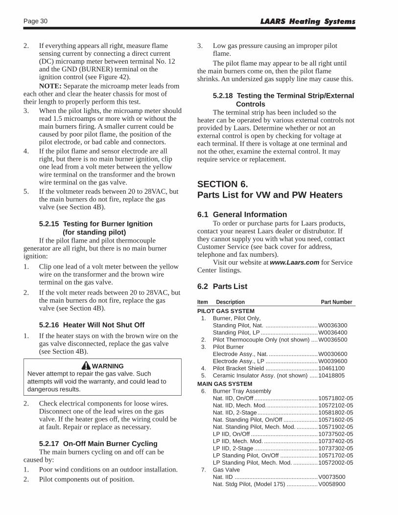
SECTION 6.Parts List6.1 General Information ..................................... 306.2 Parts List ..................................................... 30
Mighty Therm Volume Water Heaters Page 3
SECTION 1.General Information
1.1 IntroductionThis manual provides installation, operating, and
maintenance instructions for Models VW and PWVolume Water Heaters, Sizes 175 through 400. Reviewall application and installation procedures completelybefore proceeding with the installation. Experience hasshown that most operating problems are caused byimproper installation.
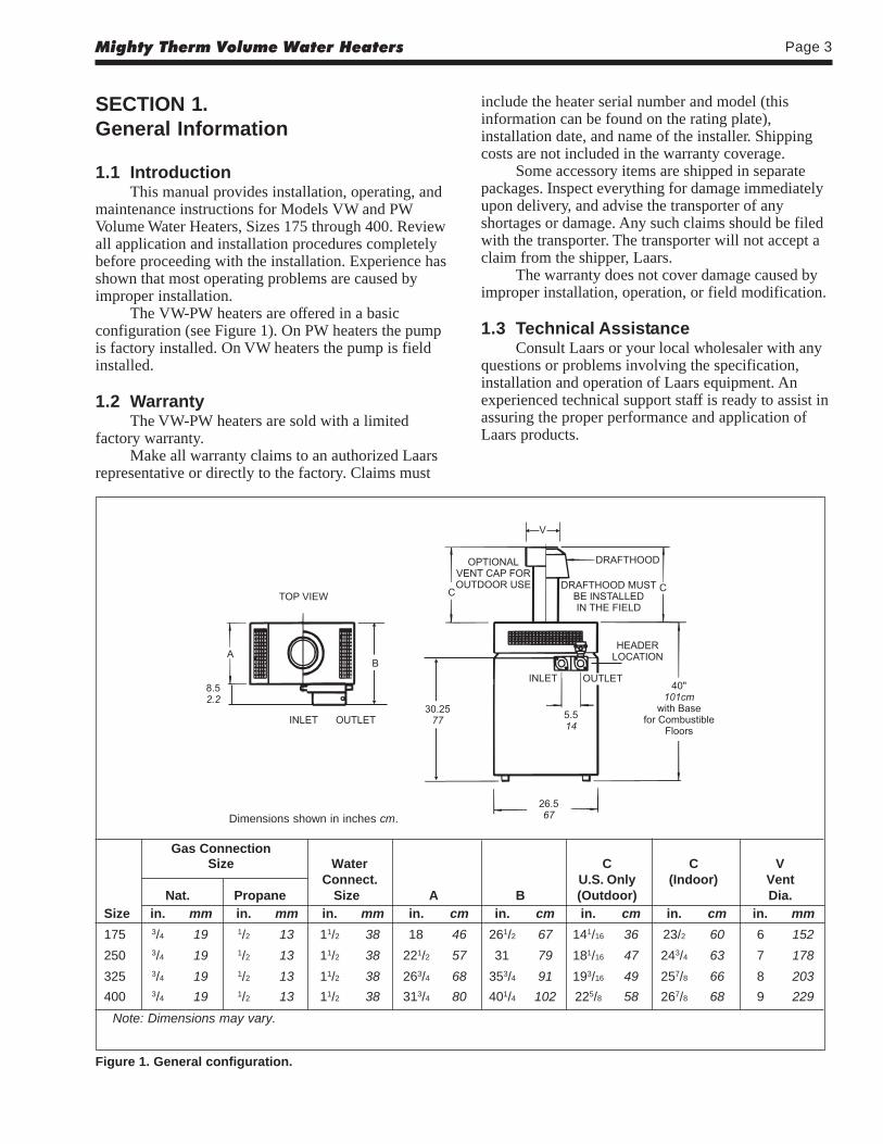
The VW-PW heaters are offered in a basicconfiguration (see Figure 1). On PW heaters the pumpis factory installed. On VW heaters the pump is fieldinstalled.
1.2 WarrantyThe VW-PW heaters are sold with a limited
factory warranty.Make all warranty claims to an authorized Laars
representative or directly to the factory. Claims must
include the heater serial number and model (thisinformation can be found on the rating plate),installation date, and name of the installer. Shippingcosts are not included in the warranty coverage.
Some accessory items are shipped in separatepackages. Inspect everything for damage immediatelyupon delivery, and advise the transporter of anyshortages or damage. Any such claims should be filedwith the transporter. The transporter will not accept aclaim from the shipper, Laars.
The warranty does not cover damage caused byimproper installation, operation, or field modification.
1.3 Technical AssistanceConsult Laars or your local wholesaler with any
questions or problems involving the specification,installation and operation of Laars equipment. Anexperienced technical support staff is ready to assist inassuring the proper performance and application ofLaars products.
Gas ConnectionSize Water C C V
Connect. U.S. Only (Indoor) VentNat. Propane Size A B (Outdoor) Dia.
Size in. mm in. mm in. mm in. cm in. cm in. cm in. cm in. mm
175 3/4 19 1/2 13 11/2 38 18 46 261/2 67 141/16 36 23/2 60 6 152
250 3/4 19 1/2 13 11/2 38 221/2 57 31 79 181/16 47 243/4 63 7 178
325 3/4 19 1/2 13 11/2 38 263/4 68 353/4 91 193/16 49 257/8 66 8 203
400 3/4 19 1/2 13 11/2 38 313/4 80 401/4 102 225/8 58 267/8 68 9 229
Note: Dimensions may vary.
Figure 1. General configuration.
Dimensions shown in inches cm.
LAARS Heating SystemsPage 4
number for the drafthood is on the heater rating plate.Follow this procedure to make the conversion:
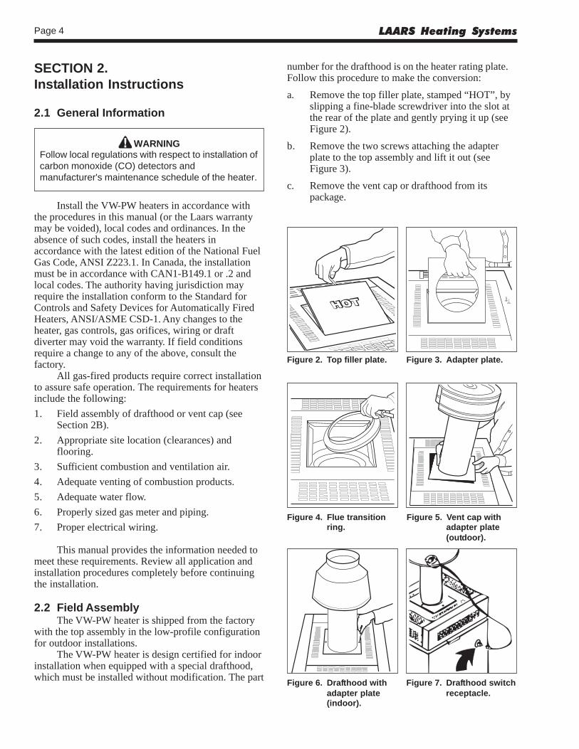
a. Remove the top filler plate, stamped “HOT”, byslipping a fine-blade screwdriver into the slot atthe rear of the plate and gently prying it up (seeFigure 2).
b. Remove the two screws attaching the adapterplate to the top assembly and lift it out (seeFigure 3).
c. Remove the vent cap or drafthood from itspackage.
SECTION 2.Installation Instructions
2.1 General Information
WARNINGFollow local regulations with respect to installation ofcarbon monoxide (CO) detectors andmanufacturer's maintenance schedule of the heater.
Install the VW-PW heaters in accordance withthe procedures in this manual (or the Laars warrantymay be voided), local codes and ordinances. In theabsence of such codes, install the heaters inaccordance with the latest edition of the National FuelGas Code, ANSI Z223.1. In Canada, the installationmust be in accordance with CAN1-B149.1 or .2 andlocal codes. The authority having jurisdiction mayrequire the installation conform to the Standard forControls and Safety Devices for Automatically FiredHeaters, ANSI/ASME CSD-1. Any changes to theheater, gas controls, gas orifices, wiring or draftdiverter may void the warranty. If field conditionsrequire a change to any of the above, consult thefactory.
All gas-fired products require correct installationto assure safe operation. The requirements for heatersinclude the following:
1. Field assembly of drafthood or vent cap (seeSection 2B).
2. Appropriate site location (clearances) andflooring.
3. Sufficient combustion and ventilation air.
4. Adequate venting of combustion products.
5. Adequate water flow.
6. Properly sized gas meter and piping.
7. Proper electrical wiring.
This manual provides the information needed tomeet these requirements. Review all application andinstallation procedures completely before continuingthe installation.
2.2 Field AssemblyThe VW-PW heater is shipped from the factory
with the top assembly in the low-profile configurationfor outdoor installations.
The VW-PW heater is design certified for indoorinstallation when equipped with a special drafthood,which must be installed without modification. The part
Figure 2. Top filler plate. Figure 3. Adapter plate.
Figure 4. Flue transition Figure 5. Vent cap withring. adapter plate
(outdoor).
Figure 6. Drafthood with Figure 7. Drafthood switchadapter plate receptacle.(indoor).
Mighty Therm Volume Water Heaters Page 5
d. Disengage the flue transition ring from the stackextension and place it on top of the collectorassembly as shown in Figure 4.
e. Slide the adapter plate over the bottom of thestack extension as shown in Figure 5. Fit thestack extension down over the flue transitionring. Seat the adapter plate on the top assemblyand secure it with two screws (see Figure 6).
f. Indoor models, size 175 and 250 only, require anadapter cable (included with product). The cableconnects the blocked vent safety switch (BVSS)on the bell of the external draft hood to the 6-position Molex plug on the side of the unit (seeFigure 7). Refer to instruction sheet includedwith cable.
2.3 Site Location2.3.1 Installation Information
WARNINGImproper installation or maintenance can causenausea or asphyxiation from carbon monoxide influe gases which could result in severe injury,property damage, or death.
Avoid placing the heater in locations where it canbe damaged by water or condensate leakage. If this isnot possible, provide a suitable drain pan to catch anddivert any leakage. The pan must not block naturalflow of air around the heater.
Locate the heater to provide adequate clearanceon all sides for inspection, service and to provideadequate air circulation for proper operation.
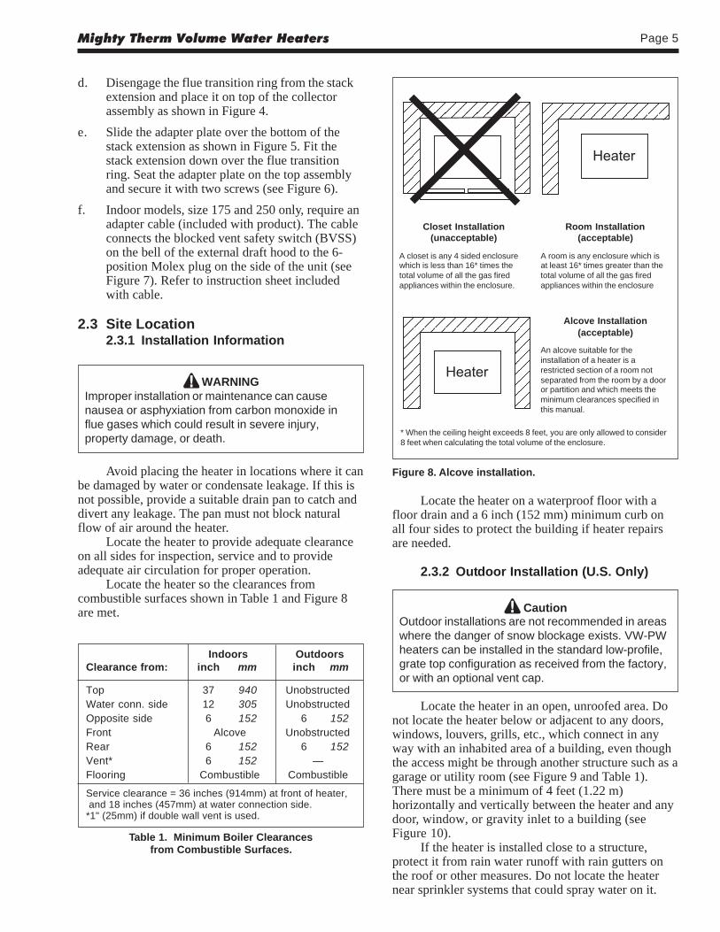
Locate the heater so the clearances fromcombustible surfaces shown in Table 1 and Figure 8are met.
Figure 8. Alcove installation.
Closet Installation(unacceptable)
A closet is any 4 sided enclosurewhich is less than 16* times thetotal volume of all the gas firedappliances within the enclosure.
Room Installation(acceptable)
A room is any enclosure which isat least 16* times greater than thetotal volume of all the gas firedappliances within the enclosure
Alcove Installation(acceptable)
An alcove suitable for theinstallation of a heater is arestricted section of a room notseparated from the room by a dooror partition and which meets theminimum clearances specified inthis manual.
* When the ceiling height exceeds 8 feet, you are only allowed to consider8 feet when calculating the total volume of the enclosure.
Indoors OutdoorsClearance from: inch mm inch mm
Top 37 940 UnobstructedWater conn. side 12 305 UnobstructedOpposite side 6 152 6 152Front Alcove UnobstructedRear 6 152 6 152Vent* 6 152 —Flooring Combustible Combustible
Service clearance = 36 inches (914mm) at front of heater, and 18 inches (457mm) at water connection side.*1" (25mm) if double wall vent is used.
Table 1. Minimum Boiler Clearancesfrom Combustible Surfaces.
Locate the heater on a waterproof floor with afloor drain and a 6 inch (152 mm) minimum curb onall four sides to protect the building if heater repairsare needed.
2.3.2 Outdoor Installation (U.S. Only)
CautionOutdoor installations are not recommended in areaswhere the danger of snow blockage exists. VW-PWheaters can be installed in the standard low-profile,grate top configuration as received from the factory,or with an optional vent cap.
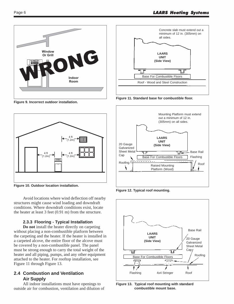
Locate the heater in an open, unroofed area. Donot locate the heater below or adjacent to any doors,windows, louvers, grills, etc., which connect in anyway with an inhabited area of a building, even thoughthe access might be through another structure such as agarage or utility room (see Figure 9 and Table 1).There must be a minimum of 4 feet (1.22 m)horizontally and vertically between the heater and anydoor, window, or gravity inlet to a building (seeFigure 10).
If the heater is installed close to a structure,protect it from rain water runoff with rain gutters onthe roof or other measures. Do not locate the heaternear sprinkler systems that could spray water on it.
LAARS Heating SystemsPage 6
Figure 11. Standard base for combustible floor.
Figure 13. Typical roof mounting with standardcombustible mount base.
Figure 12. Typical roof mounting.Figure 10. Outdoor location installation.
Figure 9. Incorrect outdoor installation.
Concrete slab must extend out aminimum of 12 in. (305mm) onall sides.
LAARSUNIT
(Side View)
Base For Combustible Floors
Roof - Wood and Steel Construction
Mounting Platform must extendout a minimum of 12 in.(305mm) on all sides.
LAARSUNIT
(Side View)
Base For Combustible Floors
Raised MountingPlatform (Wood)
20 GaugeGalvanizedSheet MetalCap
Roofing
Base Rail
Flashing
Roof
LAARSUNIT
(Side View)
Base For Combustible Floors
Flashing 4x4 Stringer Roof
Base Rail
20 GaugeGalvanizedSheet MetalCap
Roofing
Avoid locations where wind deflection off nearbystructures might cause wind loading and downdraftconditions. Where downdraft conditions exist, locatethe heater at least 3 feet (0.91 m) from the structure.
2.3.3 Flooring - Typical InstallationDo not install the heater directly on carpeting
without placing a non-combustible platform betweenthe carpeting and the heater. If the heater is installed ina carpeted alcove, the entire floor of the alcove mustbe covered by a non-combustible panel. The panelmust be strong enough to carry the total weight of theheater and all piping, pumps, and any other equipmentattached to the heater. For rooftop installation, seeFigure 11 through Figure 13.
2.4 Combustion and VentilationAir SupplyAll indoor installations must have openings to
outside air for combustion, ventilation and dilution of
Mighty Therm Volume Water Heaters Page 7
Method 1:Two permanent openings, one commencing
within 12" (30 cm) of the top and one commencingwithin 12" (30 cm) of the bottom of the enclosure shallbe provided. The openings shall communicatedirectly, or by ducts, with the outdoors or spaces thatfreely communicate with the outdoors. When directlycommunicating with the outdoors directly, or throughvertical ducts, each opening shall have a minimum freearea of 1 square inch per 4000 Btu/hr (550 square mm/kW) of total input rating of all equipment in theenclosure. When communicating to the outdoorsthrough horizontal ducts, each opening shall have aminimum free area of not less than 1 square inch per2000 Btu/hr (1100 square mm/kW) of total inputrating of all equipment in the enclosure.
Method 2:One permanent opening, commencing within
12" (30 cm) of the top of the enclosure shall bepermitted. The opening shall directly communicatewith the outdoors or shall communicate through avertical or horizontal duct to the outdoors or spacesthat directly communicate with the outdoors, and shallhave a minimum free area of 1 square inch per 3000Btu/hr (734 square mm/kW) of the total input rating ofall equipment located in the enclosure. This openingmust not be less than the sum of the areas of all ventconnectors in the confined space.
Other methods of introducing combustion andventilation air are acceptable, providing they conformto the requirements in ANSI Z223.1, or applicablecodes.
In Canada, Table 2 does not apply. Consult localbuilding and safety codes or, in absence of suchrequirements, follow CAN/CGA B149.
NOTE: Check with louver manufacturers fornet free area of louvers. If screens or louvers areinstalled, add 50 percent for each screen/louver to thenet free area Check all local codes applicable tocombustion air.
2.4.1 Outdoor Air SupplyWhen combustion air comes directly through an
outside wall, each opening must have a minimum freearea of at least one square inch for each 4,000 BTU/hinput of the total input rating of all appliances in theenclosed area. (In Canada, refer to CGAB149.1 and .2.)
2.4.2 Indoor Air SupplyConfined and non-confined areas have different
requirements for installation. Consult the latest editionof the National Gas Code for installation requirements.
2.4.3 Exhaust Fans or VentsAny equipment which uses air or removes air
from the heater room can use up the combustion air
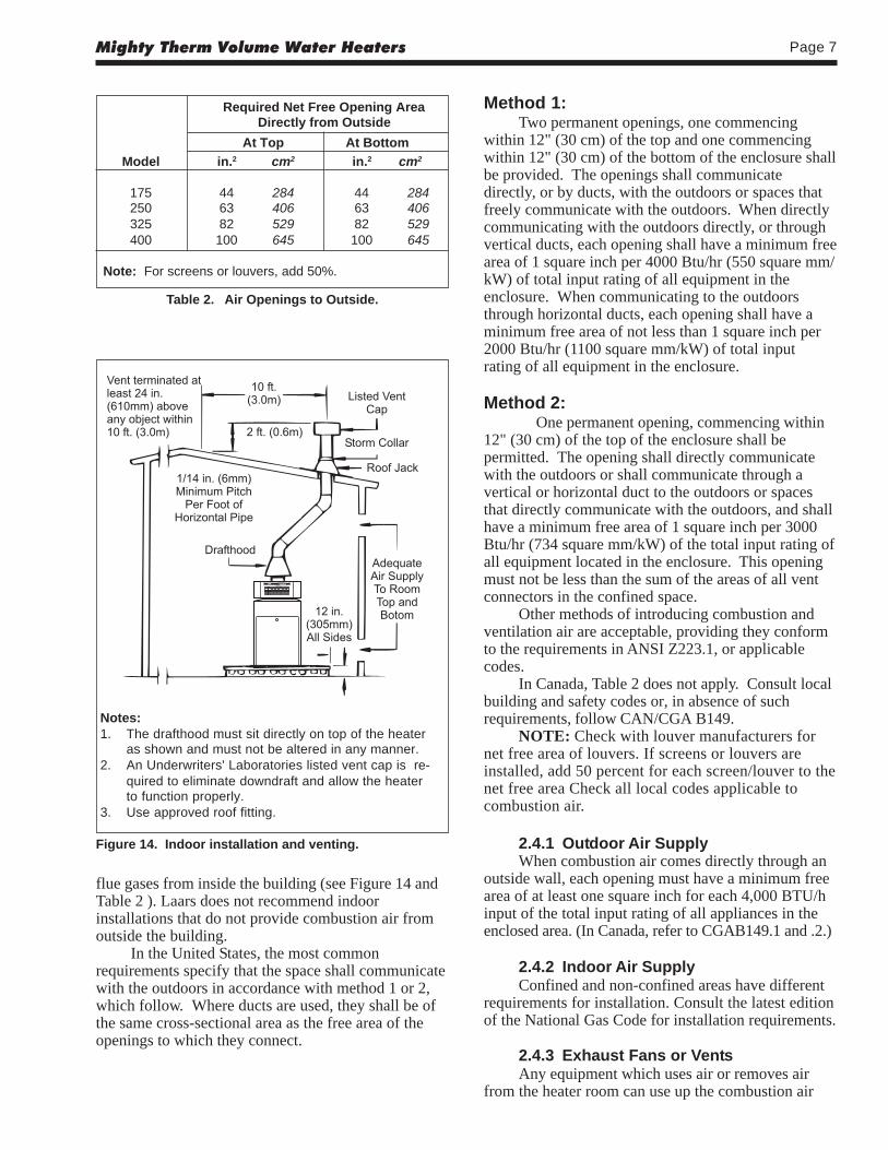
Required Net Free Opening AreaDirectly from Outside
At Top At Bottom
Model in.2 cm2 in.2 cm2
175 44 284 44 284250 63 406 63 406325 82 529 82 529400 100 645 100 645
Note: For screens or louvers, add 50%.
Table 2. Air Openings to Outside.
Figure 14. Indoor installation and venting.
Notes:1. The drafthood must sit directly on top of the heater
as shown and must not be altered in any manner.2. An Underwriters' Laboratories listed vent cap is re-
quired to eliminate downdraft and allow the heaterto function properly.
3. Use approved roof fitting.
flue gases from inside the building (see Figure 14 andTable 2 ). Laars does not recommend indoorinstallations that do not provide combustion air fromoutside the building.
In the United States, the most commonrequirements specify that the space shall communicatewith the outdoors in accordance with method 1 or 2,which follow. Where ducts are used, they shall be ofthe same cross-sectional area as the free area of theopenings to which they connect.
LAARS Heating SystemsPage 8
supply or reverse the natural draft action of the ventingsystem. This could cause flue products to build up inthe heater room. More air must be supplied to make upfor the decrease.
2.5 Venting of Combustion Products2.5.1 General InformationWhen installed indoors, the drafthood must be
connected to a venting system. The venting systemmust be installed by a qualified installer and inaccordance with the latest edition of ANSI Z223.1. InCanada, the installation must be in accordance withCAN1-B149.1 or .2, and any local codes that apply.
The vent pipe must have a listed vent cap, andextend at least 2 feet (0.6 m) above any object within a10 foot (3.0 m) radius.
NOTE: Do not use sheet metal screws at thesnap lock joints of Type B double-wall gas vents.
Do not weld or bolt the vent pipe to the heaterdrafthood. The weight of the stack must not rest on theheater. The drafthood and heater top must be easilyremovable for normal heater service and inspection.
WARNINGAvoid ending heater vents near air conditioning or airsupply fans. The fans can pick up exhaust flueproducts from the heater and return them inside thebuilding, creating a possible health hazard.
Avoid horizontal runs of the vent pipe and 90degree elbows, reductions, and restrictions. Horizontalruns should have at least a 1/4 inch (6.3 mm) rise perfoot in the direction of flow. Support a vent connectorfor the design and weight of the material used tomaintain clearances and physical damage and separateof joints.
Always use double-wall or insulated vent pipe(Type B or equivalent).
WARNINGIn cold weather, uninsulated outside vents can chillthe rising flue products, blocking the natural draftaction of the venting system. This can create ahealth hazard by spilling flue products into theheater room.
Avoid oversize vent piping or extremely longruns of the pipe which may cause too much coolingand condensation of flue gasses.
When the installation of a power vent or draft fanin the venting system is necessary, qualified personnel
should design the installation following goodengineering practices and all applicable codes. Asuitable draft switch must be wired into the heatercontrol circuit at the terminal designated FieldInterlock to keep the heater from firing unless there isa positive draft.
2.5.2 Replacement of Existing HeaterWhen a heater is removed from a common
venting system, the venting system may be too largefor proper venting of the other appliances connectedto it.
If replacing an existing heater with a VW or PWheater and the existing heater was connected to acommon venting system, the common venting systemmust comply with ANSI Z223.1/National FireProtection Association (NFPA) 54. When resizing anyportion of the common venting system, the commonventing system should be resized to approach theminimum size as determined using the tables in ANSIZ223.1/NFPA 54, Appendix G. In Canada, the commonventing system should be resized so the installationwill be in accordance with CAN/CGA B149.1 or .2.
2.6 Water Flow2.6.1 Reversible Water Connections
NOTE: This procedure is not recommended forthe PW pump-mounted models.
Laars ships the VW heater with the waterconnections on the right side. The VW heater can beinstalled with the water connections on either side. Itcould be necessary, or helpful, to switch theconnections to the left side to improve access forinstallation service. Have a professional servicetechnician perform this modification before installingthe heater using the following procedures:
1. Remove the front cover.
2. If there is a vent cap or drafthood installed, theymust be removed before removing the grate topassembly. On indoor installations (sizes 175-250), the drafthood switch must be disconnectedat the left side of the heater.
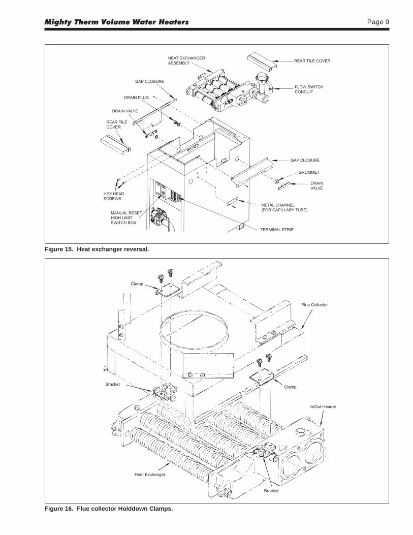
3. If the unit is in the low-profile outdoorconfiguration, remove the hex-head screws(see Figure 15) and lift the grate top assemblystraight up.
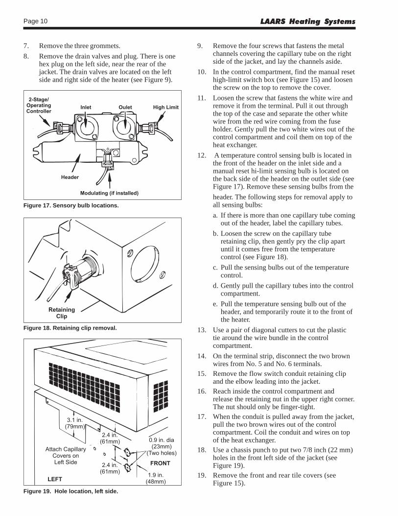
4. Remove the screws that fastens the flue collectorholddown clamps and remove the clamps (seeFigure 16).
5. Remove the flue collector assembly by lifting itout of the chassis.
6. Remove the screws that fastens the gap closuresand put them aside.
Mighty Therm Volume Water Heaters Page 9
Figure 15. Heat exchanger reversal.
Figure 16. Flue collector Holddown Clamps.
LAARS Heating SystemsPage 10
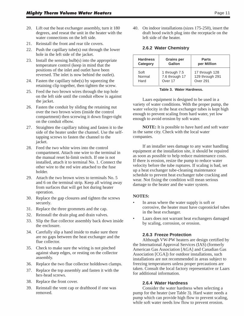
9. Remove the four screws that fastens the metalchannels covering the capillary tube on the rightside of the jacket, and lay the channels aside.
10. In the control compartment, find the manual resethigh-limit switch box (see Figure 15) and loosenthe screw on the top to remove the cover.
11. Loosen the screw that fastens the white wire andremove it from the terminal. Pull it out throughthe top of the case and separate the other whitewire from the red wire coming from the fuseholder. Gently pull the two white wires out of thecontrol compartment and coil them on top of theheat exchanger.
12. A temperature control sensing bulb is located inthe front of the header on the inlet side and amanual reset hi-limit sensing bulb is located onthe back side of the header on the outlet side (seeFigure 17). Remove these sensing bulbs from the
header. The following steps for removal apply toall sensing bulbs:
a. If there is more than one capillary tube comingout of the header, label the capillary tubes.
b. Loosen the screw on the capillary tuberetaining clip, then gently pry the clip apartuntil it comes free from the temperaturecontrol (see Figure 18).
c. Pull the sensing bulbs out of the temperaturecontrol.
d. Gently pull the capillary tubes into the controlcompartment.
e. Pull the temperature sensing bulb out of theheader, and temporarily route it to the front ofthe heater.
13. Use a pair of diagonal cutters to cut the plastictie around the wire bundle in the controlcompartment.
14. On the terminal strip, disconnect the two brownwires from No. 5 and No. 6 terminals.
15. Remove the flow switch conduit retaining clipand the elbow leading into the jacket.
16. Reach inside the control compartment andrelease the retaining nut in the upper right corner.The nut should only be finger-tight.
17. When the conduit is pulled away from the jacket,pull the two brown wires out of the controlcompartment. Coil the conduit and wires on topof the heat exchanger.
18. Use a chassis punch to put two 7/8 inch (22 mm)holes in the front left side of the jacket (seeFigure 19).
19. Remove the front and rear tile covers (seeFigure 15).
Figure 19. Hole location, left side.
Figure 17. Sensory bulb locations.
Figure 18. Retaining clip removal.
7. Remove the three grommets.
8. Remove the drain valves and plug. There is onehex plug on the left side, near the rear of thejacket. The drain valves are located on the leftside and right side of the heater (see Figure 9).
Mighty Therm Volume Water Heaters Page 11
40. On indoor installations (sizes 175-250), insert thedraft hood switch plug into the receptacle on theleft side of the heater.
2.6.2 Water Chemistry
20. Lift out the heat exchanger assembly, turn it 180degrees, and reseat the unit in the heater with thewater connections on the left side.
21. Reinstall the front and rear tile covers.22. Push the capillary tube(s) out through the lower
hole in the left side of the jacket.23. Install the sensing bulb(s) into the appropriate
temperature control (keep in mind that thepositions of the inlet and outlet have beenreversed. The inlet is now behind the outlet).
24. Fasten the capillary tube(s) by squeezing theretaining clip together, then tighten the screw.
25. Feed the two brown wires through the top holeon the left side until the conduit elbow is againstthe jacket.
26. Fasten the conduit by sliding the retaining nutover the two brown wires (inside the controlcompartment) then screwing it down finger-tighton the conduit elbow.
27. Straighten the capillary tubing and fasten it to theside of the heater under the channel. Use the self-tapping screws to fasten the channel to thejacket.
28. Feed the two white wires into the controlcompartment. Attach one wire to the terminal inthe manual reset hi-limit switch. If one is notinstalled, attach it to terminal No. 1. Connect theother wire to the red wire attached to the fuseholder.
29. Attach the two brown wires to terminals No. 5and 6 on the terminal strip. Keep all wiring awayfrom surfaces that will get hot during heateroperation.
30. Replace the gap closures and tighten the screwssecurely.
31. Replace the three grommets and the cap.32. Reinstall the drain plug and drain valves.33. Slip the flue collector assembly back down inside
the enclosure.
34. Carefully slip a hand inside to make sure thereare no gaps between the heat exchanger and theflue collector.
35. Check to make sure the wiring is not pinchedagainst sharp edges, or resting on the collectorassembly.
36. Replace the two flue collector holddown clamps.
37. Replace the top assembly and fasten it with thehex-head screws.
38. Replace the front cover.
39. Reinstall the vent cap or drafthood if one wasremoved.
Hardness Grains per PartsCategory Gallon per Million
Soft 1 through 7.5 17 through 128Normal 7.6 through 17 129 through 291Hard Over 17 Over 291
Table 3. Water Hardness.
Laars equipment is designed to be used in avariety of water conditions. With the proper pump, thewater velocity in the heat exchanger tubes is kept highenough to prevent scaling from hard water, yet lowenough to avoid erosion by soft water.
NOTE: It is possible to have hard and soft waterin the same city. Check with the local watercompanies.
If an installer sees damage to any water handlingequipment at the installation site, it should be repairedas soon as possible to help reduce maintenance costs.If there is erosion, resize the pump to reduce watervelocity before the tube ruptures. If scaling is bad, setup a heat exchanger tube-cleaning maintenanceschedule to prevent heat exchanger tube cracking andwear. Not fixing the condition will mean seriousdamage to the heater and the water system.
NOTES:
• In areas where the water supply is soft orcorrosive, the heater must have cupronickel tubesin the heat exchanger.
• Laars does not warrant heat exchangers damagedby scaling, corrosion, or erosion.
2.6.3 Freeze ProtectionAlthough VW-PW heaters are design certified by
the International Approval Services (IAS) (formerlyAmerican Gas Association [AGA] and Canadian GasAssociation [CGA]) for outdoor installations, suchinstallations are not recommended in areas subject tofreezing temperatures unless proper precautions aretaken. Consult the local factory representative or Laarsfor additional information.
2.6.4 Water HardnessConsider the water hardness when selecting a
pump for the heater (see Table 3). Hard water needs apump which can provide high flow to prevent scaling,while soft water needs low flow to prevent erosion.
LAARS Heating SystemsPage 12
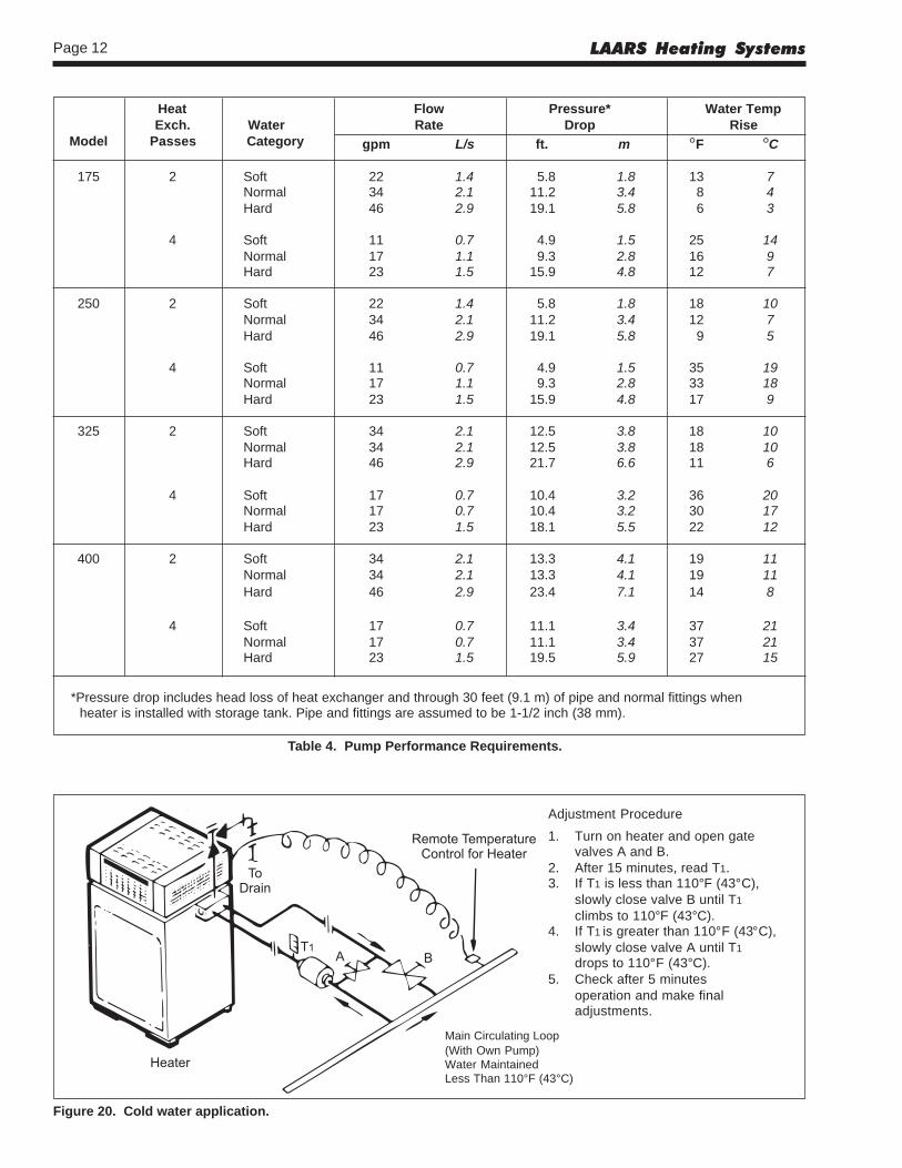
Heat Flow Pressure* Water TempExch. Water Rate Drop Rise
Model Passes Category gpm L/s ft. m °F °C
175 2 Soft 22 1.4 5.8 1.8 13 7Normal 34 2.1 11.2 3.4 8 4Hard 46 2.9 19.1 5.8 6 3
4 Soft 11 0.7 4.9 1.5 25 14Normal 17 1.1 9.3 2.8 16 9Hard 23 1.5 15.9 4.8 12 7
250 2 Soft 22 1.4 5.8 1.8 18 10Normal 34 2.1 11.2 3.4 12 7Hard 46 2.9 19.1 5.8 9 5
4 Soft 11 0.7 4.9 1.5 35 19Normal 17 1.1 9.3 2.8 33 18Hard 23 1.5 15.9 4.8 17 9
325 2 Soft 34 2.1 12.5 3.8 18 10Normal 34 2.1 12.5 3.8 18 10Hard 46 2.9 21.7 6.6 11 6
4 Soft 17 0.7 10.4 3.2 36 20Normal 17 0.7 10.4 3.2 30 17Hard 23 1.5 18.1 5.5 22 12
400 2 Soft 34 2.1 13.3 4.1 19 11Normal 34 2.1 13.3 4.1 19 11Hard 46 2.9 23.4 7.1 14 8
4 Soft 17 0.7 11.1 3.4 37 21Normal 17 0.7 11.1 3.4 37 21Hard 23 1.5 19.5 5.9 27 15
*Pressure drop includes head loss of heat exchanger and through 30 feet (9.1 m) of pipe and normal fittings whenheater is installed with storage tank. Pipe and fittings are assumed to be 1-1/2 inch (38 mm).
Main Circulating Loop(With Own Pump)Water MaintainedLess Than 110°F (43°C)
Adjustment Procedure
1. Turn on heater and open gatevalves A and B.
2. After 15 minutes, read T1.3. If T1 is less than 110°F (43°C),
slowly close valve B until T1
climbs to 110°F (43°C).4. If T1
is greater than 110°F (43°C),
slowly close valve A until T1
drops to 110°F (43°C).5. Check after 5 minutes
operation and make finaladjustments.
Figure 20. Cold water application.
Table 4. Pump Performance Requirements.
Mighty Therm Volume Water Heaters Page 13
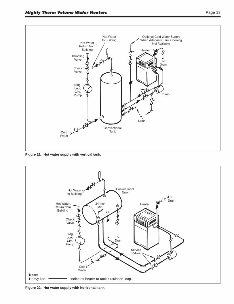
Figure 22. Hot water supply with horizontal tank.
Note:Heavy line indicates heater-to-tank circulation loop.
Figure 21. Hot water supply with vertical tank.
LAARS Heating SystemsPage 14
valve is directed to an open drain and protectedfrom freezing.
2. Install a properly sized thermal expansion tank onthe cold water supply line.
2.6.7 Pressure Relief ValveThe pressure relief valve must be installed in the
tapped opening provided in the boiler header with itsoutlet piped to a drain or floor sink. Special attentionmust be given to relief valve settings in installationswhere the boiler is located on the ground floor of a tallbuilding, or where the operating temperature of theboiler is above 210°F. In both instances, the staticpressure of the system is elevated, and could cause therelief valve to leak. Where no special setting of therelief valve is ordered, the factory will furnish a125 psi setting.
WARNINGHot water can scald! Hot water can produce
third degree burns in 6 seconds at 140°F (60°C) andin 30 seconds at 130°F (54°C).
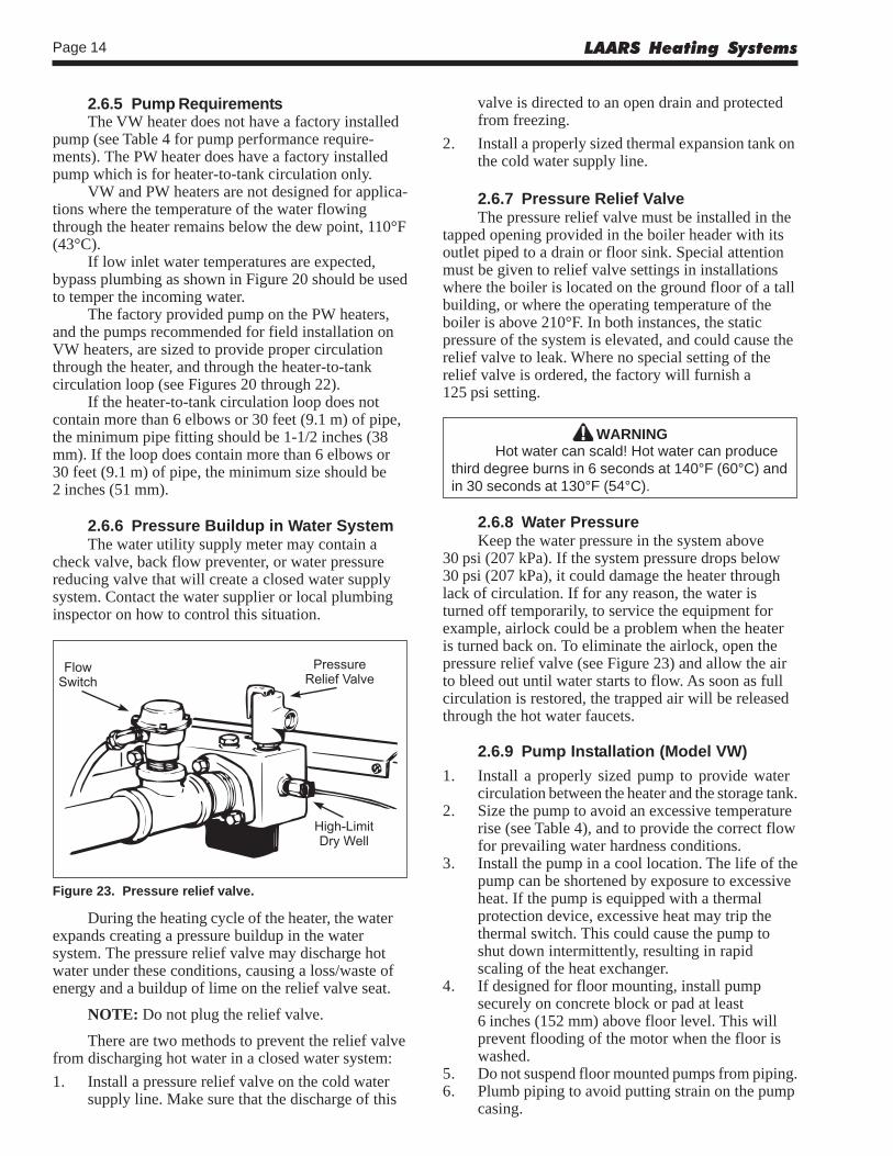
2.6.8 Water PressureKeep the water pressure in the system above
30 psi (207 kPa). If the system pressure drops below30 psi (207 kPa), it could damage the heater throughlack of circulation. If for any reason, the water isturned off temporarily, to service the equipment forexample, airlock could be a problem when the heateris turned back on. To eliminate the airlock, open thepressure relief valve (see Figure 23) and allow the airto bleed out until water starts to flow. As soon as fullcirculation is restored, the trapped air will be releasedthrough the hot water faucets.
2.6.9 Pump Installation (Model VW)
1. Install a properly sized pump to provide watercirculation between the heater and the storage tank.
2. Size the pump to avoid an excessive temperaturerise (see Table 4), and to provide the correct flowfor prevailing water hardness conditions.
3. Install the pump in a cool location. The life of thepump can be shortened by exposure to excessiveheat. If the pump is equipped with a thermalprotection device, excessive heat may trip thethermal switch. This could cause the pump toshut down intermittently, resulting in rapidscaling of the heat exchanger.
4. If designed for floor mounting, install pumpsecurely on concrete block or pad at least6 inches (152 mm) above floor level. This willprevent flooding of the motor when the floor iswashed.
5. Do not suspend floor mounted pumps from piping.6. Plumb piping to avoid putting strain on the pump
casing.
2.6.5 Pump RequirementsThe VW heater does not have a factory installed
pump (see Table 4 for pump performance require-ments). The PW heater does have a factory installedpump which is for heater-to-tank circulation only.
VW and PW heaters are not designed for applica-tions where the temperature of the water flowingthrough the heater remains below the dew point, 110°F(43°C).
If low inlet water temperatures are expected,bypass plumbing as shown in Figure 20 should be usedto temper the incoming water.
The factory provided pump on the PW heaters,and the pumps recommended for field installation onVW heaters, are sized to provide proper circulationthrough the heater, and through the heater-to-tankcirculation loop (see Figures 20 through 22).
If the heater-to-tank circulation loop does notcontain more than 6 elbows or 30 feet (9.1 m) of pipe,the minimum pipe fitting should be 1-1/2 inches (38mm). If the loop does contain more than 6 elbows or30 feet (9.1 m) of pipe, the minimum size should be2 inches (51 mm).
2.6.6 Pressure Buildup in Water SystemThe water utility supply meter may contain a
check valve, back flow preventer, or water pressurereducing valve that will create a closed water supplysystem. Contact the water supplier or local plumbinginspector on how to control this situation.
Figure 23. Pressure relief valve.
During the heating cycle of the heater, the waterexpands creating a pressure buildup in the watersystem. The pressure relief valve may discharge hotwater under these conditions, causing a loss/waste ofenergy and a buildup of lime on the relief valve seat.
NOTE: Do not plug the relief valve.
There are two methods to prevent the relief valvefrom discharging hot water in a closed water system:
1. Install a pressure relief valve on the cold watersupply line. Make sure that the discharge of this
Mighty Therm Volume Water Heaters Page 15
7. Check the oil level in the pump before startingthe heater. Oil the pump every three months. Oilpumps located in excessively hot or dustylocations once a month. Self-lubricating pumpsdo not require oiling.
8. Fill the bearing assembly to the lower level of theoverflow vent.
9. Add 5 or 6 drops of oil to the front and rear ofthe motor. Use 20W non-detergent oil.
2.6.10 Storage Tank Installation1. Be sure the floor is structurally capable of
supporting the tank when it is filled with water,and is waterproof.
2. Place the tank so that manholes, inspectioncovers, nameplates and drain valves areaccessible.
3. Be sure the tank is suitable for the water in thesystem. Some water is corrosive and requires aprotected tank. Most tanks are available withglass, plastic, or galvanized linings.
4. If the tank is glass-lined, it should be equippedwith a suitable magnesium anode. It is a goodpractice to replace the anode when it isapproximately 50 percent used. The factorywarranty on a glass-lined tank may be void if asatisfactory anode is not in place at the time of afailure or if it is consumed by cathodic action.
5. The tank must be lined if a water softener isinstalled in the system.
6. Make sure the tank connections in the heater-tank circulating loop are the proper size (seeSection 2F-5). If tappings are smaller than therecommended pipe size, a larger pump may berequired. Consult the factory if in doubt.
7. Install a pipe in the tank drain fitting that goes toa floor sink, and install a drain valve. If a floorsink is not available, install a hose bib.
8. Hot water tanks in an existing installation arelikely to have silt deposits on the bottom.Therefore, it is important to extend the pumpsuction pipe in the tank to a position near the top.Pipe the return from the heater to the bottom ofthe tank.Incorrect installation can cause rapid failure ofwater tanks due to electrolysis. Tanks must beinstalled with dialectric connections toelectrically isolate the tank from stray current.Note that use of brass or bronze connectors doesnot replace the need for dialectric connections.
2.6.11 Thermal Circulation of Hot Water in Cold Water Supply Lines
Under certain circumstances, thermal circulationwill occur in the cold water pipe supplying the waterto the heating system. This happens in a multi-storybuilding when the cold water pipe rises from its
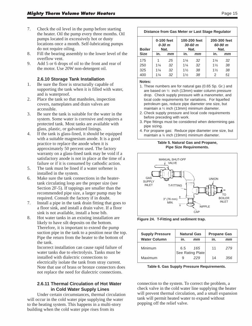
Figure 24. T-Fitting and sediment trap.
connection to the system. To correct the problem, acheck valve in the cold water line supplying the heaterwill prevent thermal circulation, and a small expansiontank will permit heated water to expand withoutpopping off the relief valve.
Distance from Gas Meter or Last Stage Regulator
0-100 feet 100-200 feet 200-300 feet0-30 m 30-60 m 60-90 m
Boiler Nat. Nat. Nat.Size in. mm in. mm in. mm
175 1 25 1¼ 32 1¼ 32250 1¼ 32 1¼ 32 1½ 38325 1¼ 32 1½ 38 1½ 38400 1¼ 32 1½ 38 2 51
Notes:1. These numbers are for natural gas (0.65 Sp. Gr.) and
are based on ½ inch (13mm) water column pressuredrop. Check supply pressure with a manometer, andlocal code requirements for variations. For liquefiedpetroleum gas, reduce pipe diameter one size, butmaintain a ½ inch (13mm) minimum diameter.
2. Check supply pressure and local code requirementsbefore preceding with work.
3. Pipe fittings must be considered when determining gaspipe sizing.
4. For propane gas: Reduce pipe diameter one size, butmaintain a ¾ inch (19mm) minimum diameter.
Table 5. Natural Gas and Propane,Pipe Size Requirements.
Supply Pressure Natural Gas Propane Gas
Water Column in. mm in. mm
Minimum 6.5 165 11 279See Rating Plate
Maximum 9 229 14 356
Table 6. Gas Supply Pressure Requirements.
LAARS Heating SystemsPage 16
10. The correct burner manifold gas pressure isstamped on the rating plate. The regulator on thegas valve is preset at the factory, and does notnormally need adjustment.
11. Before operating the heater, test the complete gassupply system and all connections for leaks usinga soap solution.
CautionSince some leak test solutions (including soap andwater) may cause corrosion or stress cracking, rinsethe piping with water after testing.
2.7.2 Special Precautionsfor Propane Gas
Liquefied petroleum (LP) gas is heavier than air.Therefore, do not install heaters using LP gas in a pitor locations where gas might collect. Locate heaters asafe distance from LP gas storage and fillingequipment. Consult local codes and fire protectionauthorities about specific installation restrictions.
2.8 Electrical Wiring
WARNINGElectrically ground the heater in accordance with thelatest edition of the National Electrical Code, ANSI/NFPA 70. In Canada, use C22.1. Do not rely on thegas or water piping to ground the metal parts of theheater. Often, plastic pipe or dielectric unions isolatethe heater electrically. Service and maintenancepersonnel who work on or around the heater may bestanding on wet floors and could be electrocuted byan underground heater.
1. Check heater wiring and pump for correctvoltage, frequency, and phase. Check to make
2.7 Gas Supply and Piping2.7.1 General InstructionsReview the following instructions before
continuing the installation.
WARNINGThe conversion of heaters from natural gas topropane gas, or propane to natural, must be done bya professional service technician. Laars provides kitsand detailed instructions for converting the heater.Changing burner and/or pilot orifices is prohibited.The installer must add and sign a gas conversion tagwhen the conversion is made.
1. Gas piping installation must be in accordancewith the latest edition of ANSI Z223.1. InCanada, the installation must be in accordancewith CAN1-B149.1 or .2 and all local codes thatapply.
2. Check the rating plate to make sure the heater isfitted for the type of gas being used. Laarsheaters are normally equipped to operate below a2000 foot (609 m) altitude. Heaters equipped tooperate at higher altitudes have appropriatestickers or tags attached.
3. If a gas pressure regulator is required, theinstallation must be in accordance with the latestedition of ANSI Z223. In Canada, the installationmust be in accordance with CAN1-B149.1 or .2and all local codes that apply.
4. The figures in Table 5 should be used to size thegas piping from the gas meter to the heater.
5. Install a sediment trap (drip leg) ahead of the gascontrols (see Figure 24 ). Fit the trap with athreaded cap which can be removed for cleaning.
6. Install a manual gas shutoff valve for service andsafety. Check the local codes.
7. Disconnect the heater and its individual shutoffvalve from the supply gas system during pressuretest of the system at pressures higher than 1/2 psi(3.4 kPa).
8. Gas supply pressures to the heater are listed inTable 6.
NOTE: The heater and all other gas appliancessharing the heater gas supply line must be firing atmaximum capacity to properly measure the inletsupply pressure. Low gas pressure could indicatean under-sized gas meter and/or obstructed gassupply line.
9. Do not exceed the maximum inlet gas pressuresspecified. Excessive pressure will result indamage to the heater's gas controls. Theminimum pressures specified is for gas inputadjustment.
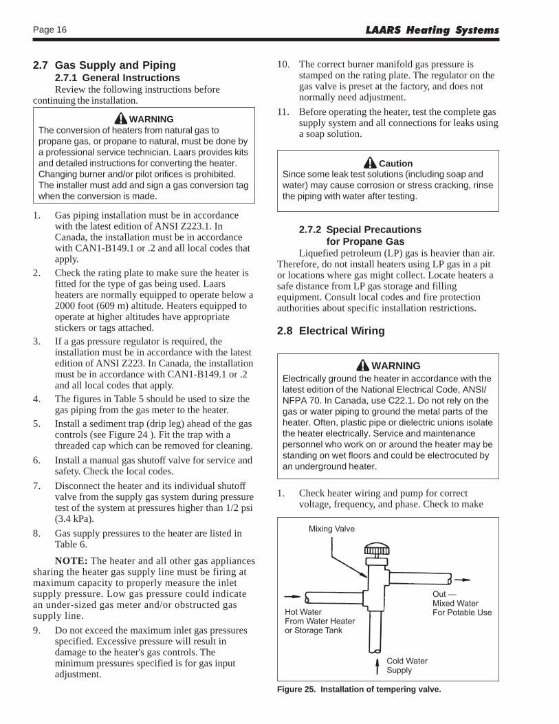
Figure 25. Installation of tempering valve.
Mighty Therm Volume Water Heaters Page 17
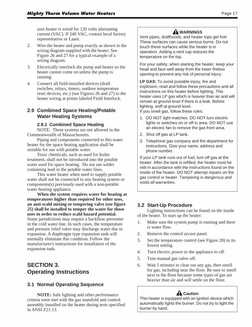
WARNINGSVent pipes, drafthoods, and heater tops get hot!These surfaces can cause serious burns. Do nottouch these surfaces while the heater is inoperation. Adding a vent cap reduces thetemperature on the top.
For your safety, when starting the heater, keep yourhead and face well away from the lower fireboxopening to prevent any risk of personal injury.
LP GAS: To avoid possible injury, fire andexplosion, read and follow these precautions and allinstructions on this heater before lighting. Thisheater uses LP gas which is heavier than air and willremain at ground level if there is a leak. Beforelighting, sniff at ground level.If you smell gas, follow these rules:
1. DO NOT light matches. DO NOT turn electriclights or switches on or off in area. DO NOT usean electric fan to remove the gas from area.
2. Shut off gas at LP tank.
3. Telephone gas company and fire department forinstructions. Give your name, address andphone number.
If your LP tank runs out of fuel, turn off gas at theheater. After the tank is refilled, the heater must berelit in accordance with the instructions found on theinside of the heater. DO NOT attempt repairs on thegas control or heater. Tampering is dangerous andvoids all warranties.
3.2 Start-Up ProcedureLighting instructions can be found on the inside
of the heater. To start up the heater:
1. Make sure the system pump is running and thereis water flow.
2. Remove the control access panel.
3. Set the temperature control (see Figure 28) to itslowest setting.
4. Turn electric power to the appliance to off.
5. Turn manual gas valve off.
6. Wait 5 minutes to clear out any gas, then smellfor gas, including near the floor. Be sure to smellnext to the floor because some types of gas areheavier than air and will settle on the floor.
CautionThis heater is equipped with an ignition device whichautomatically lights the burner. Do not try to light theburner by hand.
sure heater is wired for 120 volts alternatingcurrent (VAC). If 240 VAC, contact local factoryrepresentative or Laars.
2. Wire the heater and pump exactly as shown in thewiring diagram supplied with the heater. SeeFigure 26 and 27 for a typical example of awiring diagram.
3. Electrically interlock the pump and heater so theheater cannot come on unless the pump isrunning.
4. Connect all field-installed devices (draftswitches, relays, timers, outdoor temperaturereset devices, etc.) (see Figures 26 and 27) to theheater wiring at points labeled Field Interlock.
2.9 Combined Space Heating/PotableWater Heating Systems
2.9.1 Combined Space HeatingNOTE: These systems are not allowed in the
Commonwealth of Massachusetts.Piping and components connected to this water
heater for the space heating application shall besuitable for use with potable water.
Toxic chemicals, such as used for boilertreatment, shall not be introduced into the potablewater used for space heating. Do not use soldercontaining lead in the potable water lines.
This water heater when used to supply potablewater shall not be connected to any heating system orcomponents(s) previously used with a non-potablewater heating appliance.
When the system requires water for heating attemperatures higher than required for other uses,an anti-scald mixing or tempering valve (see figure25) shall be installed to temper the water for thoseuses in order to reduce scald hazard potential.Some jurisdictions may require a backflow preventerin the cold water line. In such cases, the temperatureand pressure relief valve may discharge water due toexpansion. A diaphragm type expansion tank willnormally eliminate this condition. Follow themanufacturer's instructions for installation of theexpansion tank.
SECTION 3.Operating Instructions
3.1 Normal Operating Sequence
NOTE: Safe lighting and other performancecriteria were met with the gas manifold and controlassembly installed on the heater during tests specifiedin ANSI Z21.13.
LAARS Heating SystemsPage 18
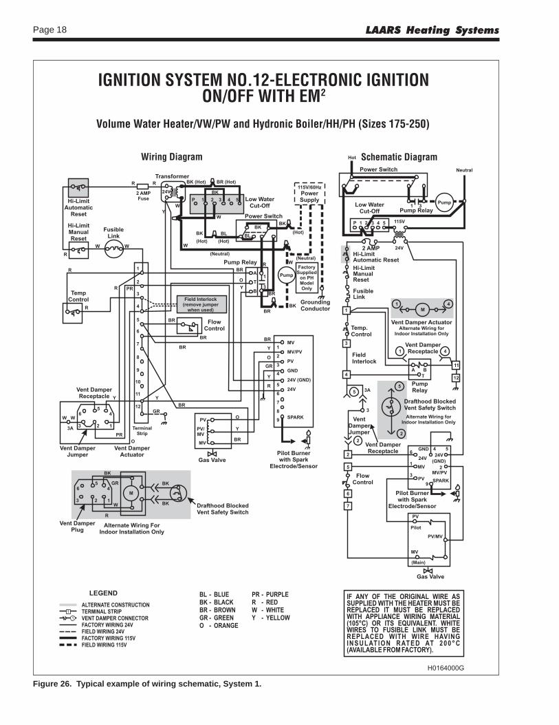
Figure 26. Typical example of wiring schematic, System 1.
Mighty Therm Volume Water Heaters Page 19
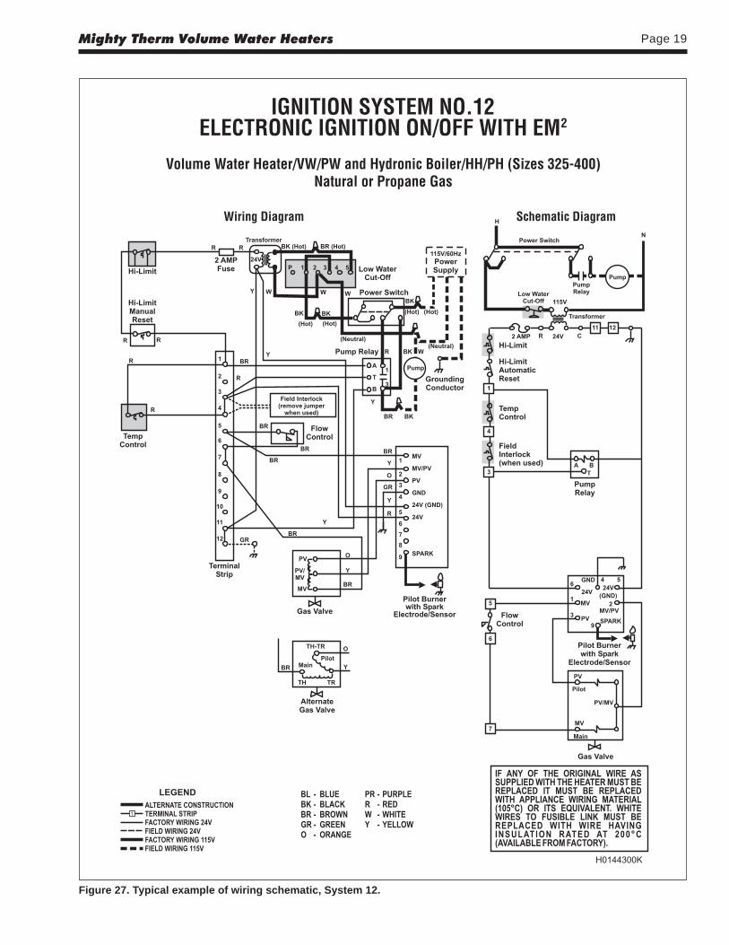
Figure 27. Typical example of wiring schematic, System 12.

LAARS Heating SystemsPage 20
hot water in the application.After a setting has been chosen for the tank
temperature control, set the heater temperature control10°F (6°C) higher. The heater’s temperature controlsenses the inlet water temperature to the heater. Theheater’s manual reset high limit (and automatic resethigh limit, if applicable) senses heater outlettemperature.
If the unit is equipped with an automatic resethigh limit, set the automatic reset high limit 20°F(11°C) above the outlet temperature to avoid nuisancelockouts. Set the manual reset high limit 5°F (3°C)above the automatic reset high limit.
For units that only have a manual reset high limit(no automatic reset high limit), set the manual resethigh limit 20°F (11°C) above the outlet temperature toavoid nuisance lockouts.
Example, Imperial units: If the tank temperatureis set to 140°F, set the heater’s temperature control to150°F (140°F + 10°F). Further, if the temperature risethrough the heater is 25°F, the outlet temperature willbe 175°F (150°F + 25°F). Therefore, set the automaticreset high limit to 195°F (170°F + 20°F), and themanual reset high limit to 200°F (195°F + 5°F).
Example, Metric units: If the tank temperature isset to 60°C, set the heater’s temperature control to66°C (60°C + 6°C). Further, if the temperature risethrough the heater is 15°C, the outlet temperature willbe 81°C (66°C + 15°C). Therefore, set the automaticreset high limit to 92°C (81°C + 11°C), and themanual reset high limit to 95°C (92°C + 3°C).
3.3.2. Internal Water Heater TemperatureControl:
When an external control is not used, thecirculator between the heater and the storage tank mustrun continuously, so that the heater’s temperaturecontrol can detect and control the water temperature inthe storage tank. The water heater’s temperaturecontrol is adjusted to its lowest temperature position(130°F, 54°C) when shipped from the factory. This isthe preferred starting point for setting the temperaturecontrol.
If the unit is equipped with an automatic resethigh limit, set the automatic reset high limit 20°F(11°C) above the outlet temperature to avoid nuisancelockouts. Set the manual reset high limit 5°F (3°C)above the automatic reset high limit.
For units that only have a manual reset high limit(no automatic reset high limit), set the manual resethigh limit 20°F (11°C) above the outlet temperature toavoid nuisance lockouts.
Example, Imperial units: If the heater’stemperature control is set to 130°F, and thetemperature rise through the heater is 25°F, the outlettemperature will be 155°F (130°F + 25°F). Set theautomatic reset high limit to 175°F (155°F + 20°F) andset the manual reset high limit to 180°F (175°F + 5°F).
Figure 28. Temperature controls.
7. Turn manual gas valve on.8. Reset all safety devices (some units have manual
resets on hi-limit switch, low water cutoff, etc.).9. Set temperature control to desired setting.10. Replace control access panel.11. Turn electric power to the heater on.12. If the heater will not operate:
a. Turn gas to heater off following theinstructions found on the inside of the heaterand call a qualified service technician or gassupplier.
b. Turn main electrical switch off.c. Close all manual gas valves.
3.3 Setting the Temperature ControlsThe hi-limit switch is factory set, and should not
be adjusted above the factory setting.
WARNINGAdjusting the temperature control past therecommended setting can result in a scalding injury.Hot water can produce third degree burns in 6seconds at 140°F (60°C) and in 30 seconds at130°F (54°C).
3.3.1. Remote Water Heater TemperatureControl:
The water heater can be used with a field-supplied tank aquastat, sequencing control, or othertemperature control device, which will call the unit forheat when the temperature goes below the controller’ssetpoint. For the most efficient setting, set the tanktemperature at the lowest possible setting for adequate
Mighty Therm Volume Water Heaters Page 21
Electronic Pilot Standing Pilot
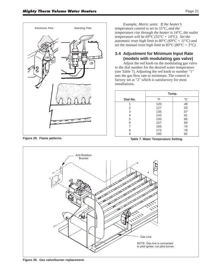
Figure 29. Flame patterns.
Example, Metric units: If the heater’stemperature control is set to 55°C, and thetemperature rise through the heater is 14°C, the outlettemperature will be 69°C (55°C + 14°C). Set theautomatic reset high limit to 80°C (69°C + 11°C) andset the manual reset high limit to 83°C (80°C + 3°C).
3.4 Adjustment for Minimum Input Rate(models with modulating gas valve)Adjust the red knob on the modulating gas valve
to the dial number for the desired water temperature(see Table 7). Adjusting the red knob to number "1"sets the gas flow rate to minimum. The control isfactory set at "2" which is satisfactory for mostinstallations.
Figure 30. Gas valve/burner replacement.
Temp.
Dial No. °F °C
1 120 492 127 533 135 574 142 615 150 666 157 697 165 748 172 789 180 82
Table 7. Water Temperature Setting.
LAARS Heating SystemsPage 22
3.5 Hi-Limit Switch CheckoutAfter running the heater for a long enough
period, bring the water temperature within the range ofthe hi-limit switch and slowly back off the high limitsetting until the heater shuts off. The main burnersshould reignite when the hi-limit switch is reset andturned back up to its original setting. The heatershould now run until it shuts off automatically onoperating control.
Should overheating occur or the gas supply failto shut off, turn off the manual gas control valve to theheater.
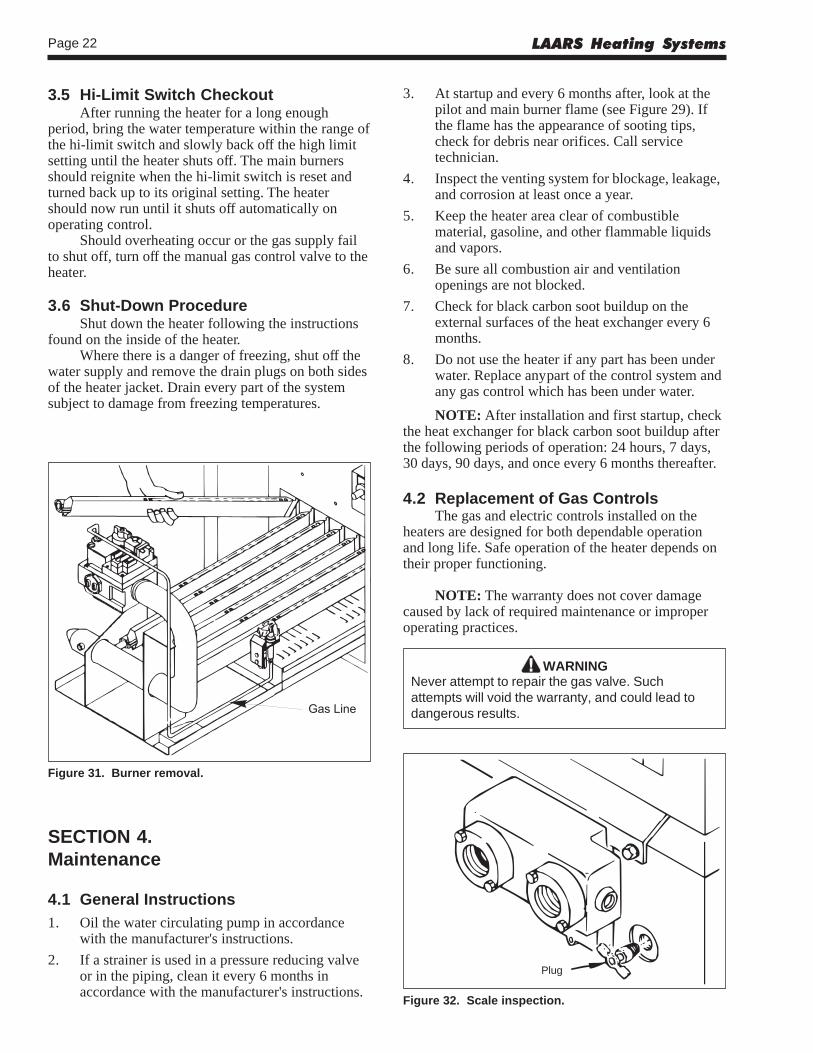
3.6 Shut-Down ProcedureShut down the heater following the instructions
found on the inside of the heater.Where there is a danger of freezing, shut off the
water supply and remove the drain plugs on both sidesof the heater jacket. Drain every part of the systemsubject to damage from freezing temperatures.
Figure 31. Burner removal.
3. At startup and every 6 months after, look at thepilot and main burner flame (see Figure 29). Ifthe flame has the appearance of sooting tips,check for debris near orifices. Call servicetechnician.
4. Inspect the venting system for blockage, leakage,and corrosion at least once a year.
5. Keep the heater area clear of combustiblematerial, gasoline, and other flammable liquidsand vapors.
6. Be sure all combustion air and ventilationopenings are not blocked.
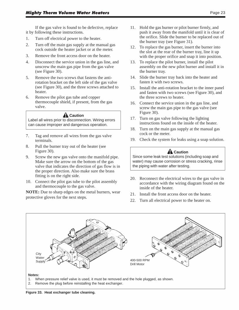
7. Check for black carbon soot buildup on theexternal surfaces of the heat exchanger every 6months.
8. Do not use the heater if any part has been underwater. Replace anypart of the control system andany gas control which has been under water.
NOTE: After installation and first startup, checkthe heat exchanger for black carbon soot buildup afterthe following periods of operation: 24 hours, 7 days,30 days, 90 days, and once every 6 months thereafter.
4.2 Replacement of Gas ControlsThe gas and electric controls installed on the
heaters are designed for both dependable operationand long life. Safe operation of the heater depends ontheir proper functioning.
NOTE: The warranty does not cover damagecaused by lack of required maintenance or improperoperating practices.
WARNINGNever attempt to repair the gas valve. Suchattempts will void the warranty, and could lead todangerous results.
SECTION 4.Maintenance
4.1 General Instructions
1. Oil the water circulating pump in accordancewith the manufacturer's instructions.
2. If a strainer is used in a pressure reducing valveor in the piping, clean it every 6 months inaccordance with the manufacturer's instructions.
Plug
Figure 32. Scale inspection.
Mighty Therm Volume Water Heaters Page 23
If the gas valve is found to be defective, replaceit by following these instructions.
1. Turn off electrical power to the heater.
2. Turn off the main gas supply at the manual gascock outside the heater jacket or at the meter.
3. Remove the front access door on the heater.
4. Disconnect the service union in the gas line, andunscrew the main gas pipe from the gas valve(see Figure 30).
5. Remove the two screws that fastens the anti-rotation bracket on the left side of the gas valve(see Figure 30), and the three screws attached toheater.
6. Remove the pilot gas tube and copperthermocouple shield, if present, from the gasvalve.
CautionLabel all wires prior to disconnection. Wiring errorscan cause improper and dangerous operation.
7. Tag and remove all wires from the gas valveterminals.
8. Pull the burner tray out of the heater (seeFigure 30).
9. Screw the new gas valve onto the manifold pipe.Make sure the arrow on the bottom of the gasvalve that indicates the direction of gas flow is inthe proper direction. Also make sure the brassfitting is on the right side.
10. Connect the pilot gas tube to the pilot assemblyand thermocouple to the gas valve.
NOTE: Due to sharp edges on the metal burners, wearprotective gloves for the next steps.
11. Hold the gas burner or pilot burner firmly, andpush it away from the manifold until it is clear ofthe orifice. Slide the burner to be replaced out ofthe burner tray (see Figure 31).
12. To replace the gas burner, insert the burner intothe slot at the rear of the burner tray, line it upwith the proper orifice and snap it into position.
13. To replace the pilot burner, install the pilotassembly on the new pilot burner and install it inthe burner tray.
14. Slide the burner tray back into the heater andfasten it with two screws.
15. Install the anti-rotation bracket to the inner paneland fasten with two screws (see Figure 30), andthe three screws to heater.
16. Connect the service union in the gas line, andscrew the main gas pipe to the gas valve (seeFigure 30).
17. Turn on gas valve following the lightinginstructions found on the inside of the heater.
18. Turn on the main gas supply at the manual gascock or the meter.
19. Check the system for leaks using a soap solution.
CautionSince some leak test solutions (including soap andwater) may cause corrosion or stress cracking, rinsethe piping with water after testing.
20. Reconnect the electrical wires to the gas valve inaccordance with the wiring diagram found on theinside of the heater.
21. Install the front access door on the heater.
22. Turn all electrical power to the heater on.
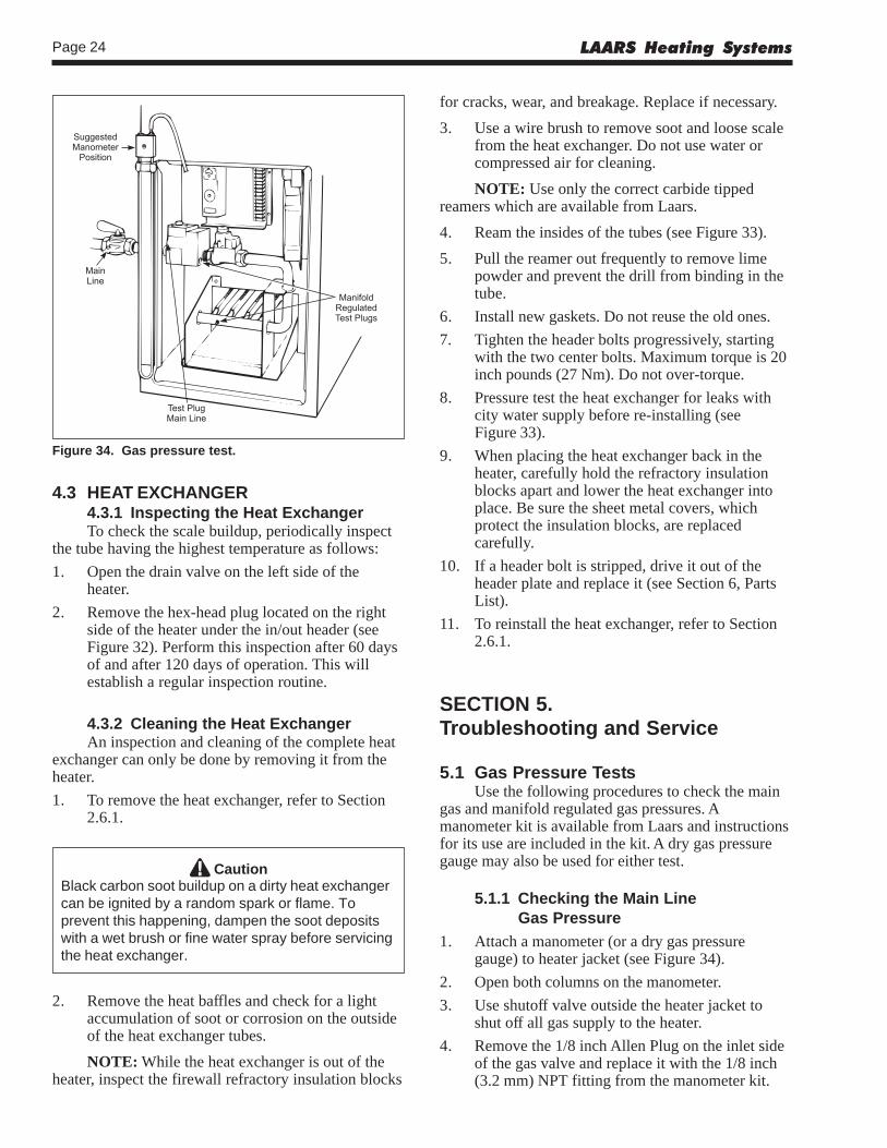
Figure 33. Heat exchanger tube cleaning.
Notes:1. When pressure relief valve is used, it must be removed and the hole plugged, as shown.2. Remove the plug before reinstalling the heat exchanger.
CityWaterSupply 400-500 RPM
Drill Motor
LAARS Heating SystemsPage 24
4.3 HEAT EXCHANGER4.3.1 Inspecting the Heat ExchangerTo check the scale buildup, periodically inspect
the tube having the highest temperature as follows:
1. Open the drain valve on the left side of theheater.
2. Remove the hex-head plug located on the rightside of the heater under the in/out header (seeFigure 32). Perform this inspection after 60 daysof and after 120 days of operation. This willestablish a regular inspection routine.
4.3.2 Cleaning the Heat ExchangerAn inspection and cleaning of the complete heat
exchanger can only be done by removing it from theheater.
1. To remove the heat exchanger, refer to Section2.6.1.
CautionBlack carbon soot buildup on a dirty heat exchangercan be ignited by a random spark or flame. Toprevent this happening, dampen the soot depositswith a wet brush or fine water spray before servicingthe heat exchanger.
2. Remove the heat baffles and check for a lightaccumulation of soot or corrosion on the outsideof the heat exchanger tubes.
NOTE: While the heat exchanger is out of theheater, inspect the firewall refractory insulation blocks
for cracks, wear, and breakage. Replace if necessary.
3. Use a wire brush to remove soot and loose scalefrom the heat exchanger. Do not use water orcompressed air for cleaning.
NOTE: Use only the correct carbide tippedreamers which are available from Laars.
4. Ream the insides of the tubes (see Figure 33).
5. Pull the reamer out frequently to remove limepowder and prevent the drill from binding in thetube.
6. Install new gaskets. Do not reuse the old ones.
7. Tighten the header bolts progressively, startingwith the two center bolts. Maximum torque is 20inch pounds (27 Nm). Do not over-torque.
8. Pressure test the heat exchanger for leaks withcity water supply before re-installing (seeFigure 33).
9. When placing the heat exchanger back in theheater, carefully hold the refractory insulationblocks apart and lower the heat exchanger intoplace. Be sure the sheet metal covers, whichprotect the insulation blocks, are replacedcarefully.
10. If a header bolt is stripped, drive it out of theheader plate and replace it (see Section 6, PartsList).
11. To reinstall the heat exchanger, refer to Section2.6.1.
SECTION 5.Troubleshooting and Service
5.1 Gas Pressure TestsUse the following procedures to check the main
gas and manifold regulated gas pressures. Amanometer kit is available from Laars and instructionsfor its use are included in the kit. A dry gas pressuregauge may also be used for either test.
5.1.1 Checking the Main LineGas Pressure
1. Attach a manometer (or a dry gas pressuregauge) to heater jacket (see Figure 34).
2. Open both columns on the manometer.
3. Use shutoff valve outside the heater jacket toshut off all gas supply to the heater.
4. Remove the 1/8 inch Allen Plug on the inlet sideof the gas valve and replace it with the 1/8 inch(3.2 mm) NPT fitting from the manometer kit.
Figure 34. Gas pressure test.
Mighty Therm Volume Water Heaters Page 25
5. Attach one end of the manometer hose to thefitting on the gas valve and the other end to themanometer.
6. Open gas supply valve to the heater to test.
7. With the main burners firing, the manometerreading should be between 6.5 and 9 inches W.C.for natural gas, and between 11 and 14 inchesW.C. for propane units (see Table 6).
5.1.2 Checking the ManifoldRegulated Gas Pressure
1. Attach a manometer (or a dry gas pressuregauge) to heater jacket (see Figure 34).
2. Open both columns on the manometer.
3. Use shutoff valve, on outside of heater jacket, toshut off all gas supply to the heater.
4. Remove the 1/8 inch (3.2 mm) NPT test plug onthe outlet side of the manifold, and replace itwith the 1/8 inch (3.2 mm) NPT fitting from themanometer kit, (see Figure 34).
5. Attach one end of the manometer hose to thefitting on the manifold and the other end to themanometer.
6. Turn on gas supply to the heater, and set thetemperature control high enough to call for heat.
7. Turn toggle switch to ON. This should activatethe main burners.
8. The manometer reading should be 4 inches(102mm) W.C. for natural gas and 9 inches(229mm) W.C. for propane gas.
9. Turn the toggle switch to OFF.
10. Shut the system down following the instructionsfound on the inside of the heater.
11. Disconnect the manometer tubing from themanifold and replace the 1/8 inch (3.2 mm) NPTfitting with the original plug.
5.2 Electrical TroubleshootingThis section describes procedures for checking
the electrical power and control components of theheater. Read all of these procedures before startingrepairs.
Problems with heaters not firing are usuallycaused by something reducing water flow through theheater, causing the protective switches in the heatersystem to shut down the heater.
The following tools are required for properservice and problem diagnosis of the heater andheating system.
1. Gas pressure test kit with range from 0 to 14inches (0 to 356 mm) W.C.
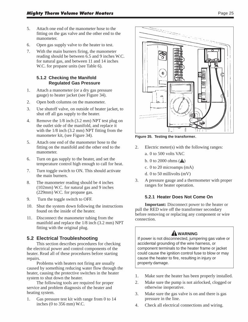
Figure 35. Testing the transformer.
2. Electric meter(s) with the following ranges:
a. 0 to 500 volts VAC
b. 0 to 2000 ohms ( )
c. 0 to 20 microamps (mA)
d. 0 to 50 millivolts (mV)
3. A pressure gauge and a thermometer with properranges for heater operation.
5.2.1 Heater Does Not Come On
Important: Disconnect power to the heater orpull the RED wire off the transformer secondarybefore removing or replacing any component or wireconnection.
WARNINGIf power is not disconnected, jumpering gas valve oraccidental grounding of the wire harness, orcomponent terminals to the heater frame or jacketcould cause the ignition control fuse to blow or maycause the heater to fire, resulting in injury orproperty damage.
1. Make sure the heater has been properly installed.
2. Make sure the pump is not airlocked, clogged orotherwise inoperative.
3. Make sure the gas valve is on and there is gaspressure in the line.
4. Check all electrical connections and wiring.
LAARS Heating SystemsPage 26
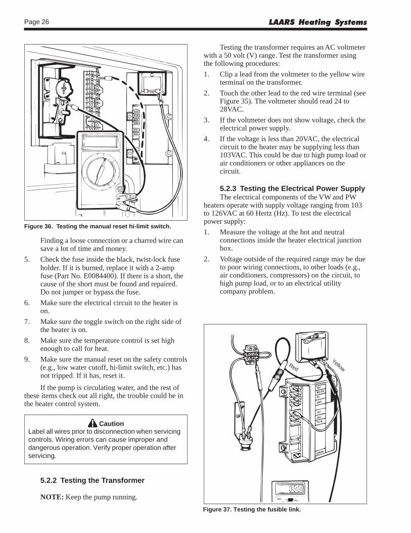
Testing the transformer requires an AC voltmeterwith a 50 volt (V) range. Test the transformer usingthe following procedures:
1. Clip a lead from the voltmeter to the yellow wireterminal on the transformer.
2. Touch the other lead to the red wire terminal (seeFigure 35). The voltmeter should read 24 to28VAC.
3. If the voltmeter does not show voltage, check theelectrical power supply.
4. If the voltage is less than 20VAC, the electricalcircuit to the heater may be supplying less than103VAC. This could be due to high pump load orair conditioners or other appliances on thecircuit.
5.2.3 Testing the Electrical Power SupplyThe electrical components of the VW and PW
heaters operate with supply voltage ranging from 103to 126VAC at 60 Hertz (Hz). To test the electricalpower supply:
1. Measure the voltage at the hot and neutralconnections inside the heater electrical junctionbox.
2. Voltage outside of the required range may be dueto poor wiring connections, to other loads (e.g.,air conditioners, compressors) on the circuit, tohigh pump load, or to an electrical utilitycompany problem.
Figure 36. Testing the manual reset hi-limit switch.
Figure 37. Testing the fusible link.
Finding a loose connection or a charred wire cansave a lot of time and money.
5. Check the fuse inside the black, twist-lock fuseholder. If it is burned, replace it with a 2-ampfuse (Part No. E0084400). If there is a short, thecause of the short must be found and repaired.Do not jumper or bypass the fuse.
6. Make sure the electrical circuit to the heater ison.
7. Make sure the toggle switch on the right side ofthe heater is on.
8. Make sure the temperature control is set highenough to call for heat.
9. Make sure the manual reset on the safety controls(e.g., low water cutoff, hi-limit switch, etc.) hasnot tripped. If it has, reset it.
If the pump is circulating water, and the rest ofthese items check out all right, the trouble could be inthe heater control system.
CautionLabel all wires prior to disconnection when servicingcontrols. Wiring errors can cause improper anddangerous operation. Verify proper operation afterservicing.
5.2.2 Testing the Transformer
NOTE: Keep the pump running.
Red
Yellow
Mighty Therm Volume Water Heaters Page 27
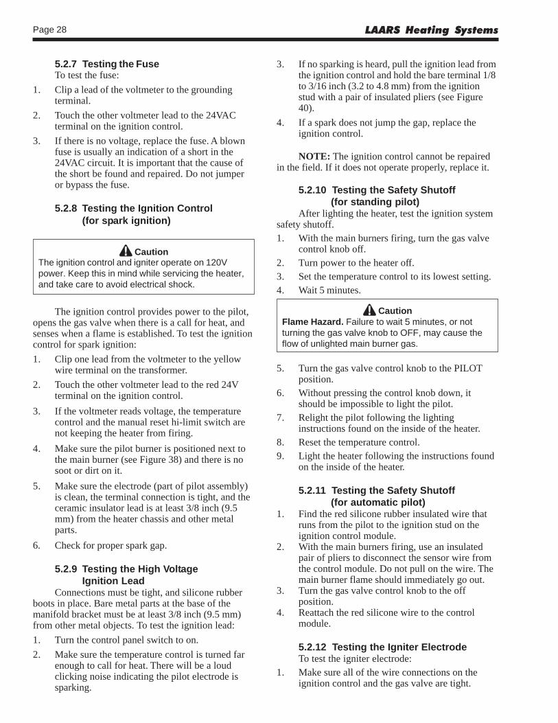
5.2.4 Testing the Manual ResetHi-Limit Switch
To test the manual reset hi-limit switch (seeFigure 36):
1. Touch the other lead of the voltmeter to bothterminals of the manual reset hi-limit switch. Thevoltmeter should read 24 to 28VAC at bothterminals.
2. If no voltage is detected at one terminal, reset themanual reset hi-limit switch by pressing the resetbutton. Check the temperature setting.
3. If after pressing the reset button there is still novoltage indicated at one terminal, replace themanual reset hi-limit switch. An open switch mayindicate excessive water temperatures orimproper setting.
5.2.5 Testing the Flow SwitchThe flow switch is a safety device that senses
water flow through the heater. When the switch sensesadequate water flow, it closes, allowing the heater tofire. If the water flow is too low, the switch remainsopen and prevents the heater from firing regardless ofthe temperature control setting.
The flow switch is factory mounted and wired.Never attempt to repair the flow switch. If the flowswitch is found to be defective, replace the flowswitch. To test the flow switch:1. Remove cap from flow switch.2. Touch a voltmeter lead to each terminal of the
flow switch.3. If the voltmeter reads voltage at each of the
terminals, the switch is good.4. If there is no voltage at one terminal, it indicates
an open switch. Check flow switch paddles todetermine if they are broken, missing or frozen.Replace the flow switch.
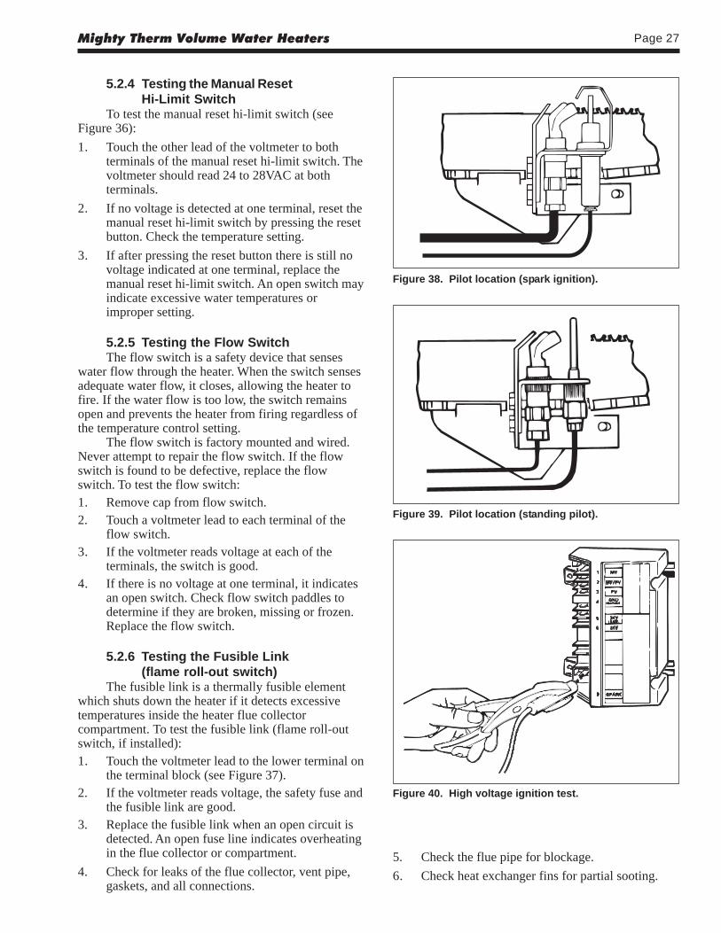
5.2.6 Testing the Fusible Link(flame roll-out switch)
The fusible link is a thermally fusible elementwhich shuts down the heater if it detects excessivetemperatures inside the heater flue collectorcompartment. To test the fusible link (flame roll-outswitch, if installed):1. Touch the voltmeter lead to the lower terminal on
the terminal block (see Figure 37).2. If the voltmeter reads voltage, the safety fuse and
the fusible link are good.3. Replace the fusible link when an open circuit is
detected. An open fuse line indicates overheatingin the flue collector or compartment.
4. Check for leaks of the flue collector, vent pipe,gaskets, and all connections.
Figure 38. Pilot location (spark ignition).
Figure 39. Pilot location (standing pilot).
Figure 40. High voltage ignition test.
5. Check the flue pipe for blockage.
6. Check heat exchanger fins for partial sooting.
LAARS Heating SystemsPage 28
5.2.7 Testing the FuseTo test the fuse:
1. Clip a lead of the voltmeter to the groundingterminal.
2. Touch the other voltmeter lead to the 24VACterminal on the ignition control.
3. If there is no voltage, replace the fuse. A blownfuse is usually an indication of a short in the24VAC circuit. It is important that the cause ofthe short be found and repaired. Do not jumperor bypass the fuse.
5.2.8 Testing the Ignition Control(for spark ignition)
CautionThe ignition control and igniter operate on 120Vpower. Keep this in mind while servicing the heater,and take care to avoid electrical shock.
The ignition control provides power to the pilot,opens the gas valve when there is a call for heat, andsenses when a flame is established. To test the ignitioncontrol for spark ignition:
1. Clip one lead from the voltmeter to the yellowwire terminal on the transformer.
2. Touch the other voltmeter lead to the red 24Vterminal on the ignition control.
3. If the voltmeter reads voltage, the temperaturecontrol and the manual reset hi-limit switch arenot keeping the heater from firing.
4. Make sure the pilot burner is positioned next tothe main burner (see Figure 38) and there is nosoot or dirt on it.
5. Make sure the electrode (part of pilot assembly)is clean, the terminal connection is tight, and theceramic insulator lead is at least 3/8 inch (9.5mm) from the heater chassis and other metalparts.
6. Check for proper spark gap.
5.2.9 Testing the High VoltageIgnition Lead
Connections must be tight, and silicone rubberboots in place. Bare metal parts at the base of themanifold bracket must be at least 3/8 inch (9.5 mm)from other metal objects. To test the ignition lead:
1. Turn the control panel switch to on.
2. Make sure the temperature control is turned farenough to call for heat. There will be a loudclicking noise indicating the pilot electrode issparking.
3. If no sparking is heard, pull the ignition lead fromthe ignition control and hold the bare terminal 1/8to 3/16 inch (3.2 to 4.8 mm) from the ignitionstud with a pair of insulated pliers (see Figure40).
4. If a spark does not jump the gap, replace theignition control.
NOTE: The ignition control cannot be repairedin the field. If it does not operate properly, replace it.
5.2.10 Testing the Safety Shutoff(for standing pilot)
After lighting the heater, test the ignition systemsafety shutoff.1. With the main burners firing, turn the gas valve
control knob off.2. Turn power to the heater off.3. Set the temperature control to its lowest setting.4. Wait 5 minutes.
CautionFlame Hazard. Failure to wait 5 minutes, or notturning the gas valve knob to OFF, may cause theflow of unlighted main burner gas.
5. Turn the gas valve control knob to the PILOTposition.
6. Without pressing the control knob down, itshould be impossible to light the pilot.
7. Relight the pilot following the lightinginstructions found on the inside of the heater.
8. Reset the temperature control.9. Light the heater following the instructions found
on the inside of the heater.
5.2.11 Testing the Safety Shutoff(for automatic pilot)
1. Find the red silicone rubber insulated wire thatruns from the pilot to the ignition stud on theignition control module.
2. With the main burners firing, use an insulatedpair of pliers to disconnect the sensor wire fromthe control module. Do not pull on the wire. Themain burner flame should immediately go out.
3. Turn the gas valve control knob to the offposition.
4. Reattach the red silicone wire to the controlmodule.
5.2.12 Testing the Igniter ElectrodeTo test the igniter electrode:
1. Make sure all of the wire connections on theignition control and the gas valve are tight.
Mighty Therm Volume Water Heaters Page 29
Thermocouple ThermocoupleAdapter
Gas Valve
MillivoltMeter
Pilot
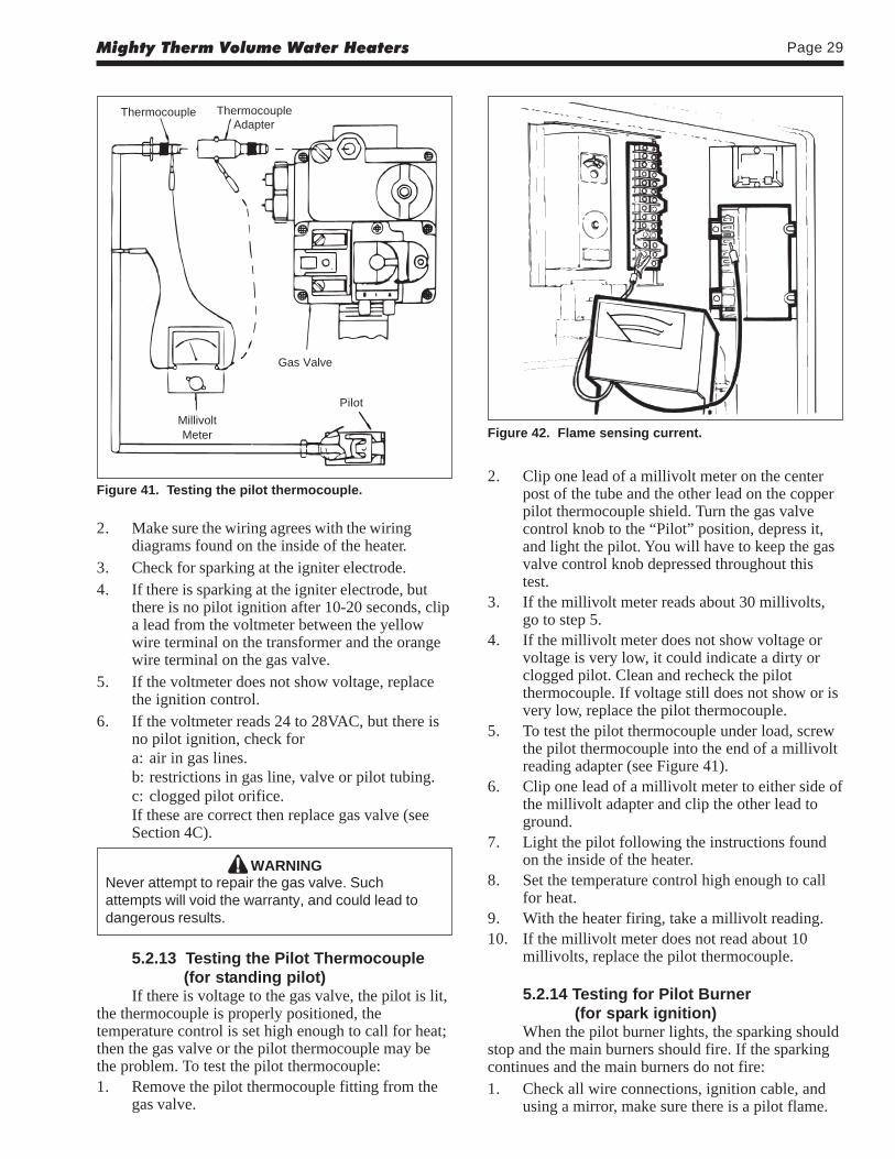
Figure 41. Testing the pilot thermocouple.2. Clip one lead of a millivolt meter on the center
post of the tube and the other lead on the copperpilot thermocouple shield. Turn the gas valvecontrol knob to the “Pilot” position, depress it,and light the pilot. You will have to keep the gasvalve control knob depressed throughout thistest.
3. If the millivolt meter reads about 30 millivolts,go to step 5.
4. If the millivolt meter does not show voltage orvoltage is very low, it could indicate a dirty orclogged pilot. Clean and recheck the pilotthermocouple. If voltage still does not show or isvery low, replace the pilot thermocouple.
5. To test the pilot thermocouple under load, screwthe pilot thermocouple into the end of a millivoltreading adapter (see Figure 41).
6. Clip one lead of a millivolt meter to either side ofthe millivolt adapter and clip the other lead toground.
7. Light the pilot following the instructions foundon the inside of the heater.
8. Set the temperature control high enough to callfor heat.
9. With the heater firing, take a millivolt reading.10. If the millivolt meter does not read about 10
millivolts, replace the pilot thermocouple.
5.2.14 Testing for Pilot Burner(for spark ignition)
When the pilot burner lights, the sparking shouldstop and the main burners should fire. If the sparkingcontinues and the main burners do not fire:1. Check all wire connections, ignition cable, and
using a mirror, make sure there is a pilot flame.
2. Make sure the wiring agrees with the wiringdiagrams found on the inside of the heater.
3. Check for sparking at the igniter electrode.4. If there is sparking at the igniter electrode, but
there is no pilot ignition after 10-20 seconds, clipa lead from the voltmeter between the yellowwire terminal on the transformer and the orangewire terminal on the gas valve.
5. If the voltmeter does not show voltage, replacethe ignition control.
6. If the voltmeter reads 24 to 28VAC, but there isno pilot ignition, check fora: air in gas lines.b: restrictions in gas line, valve or pilot tubing.c: clogged pilot orifice.If these are correct then replace gas valve (seeSection 4C).
WARNINGNever attempt to repair the gas valve. Suchattempts will void the warranty, and could lead todangerous results.
5.2.13 Testing the Pilot Thermocouple(for standing pilot)
If there is voltage to the gas valve, the pilot is lit,the thermocouple is properly positioned, thetemperature control is set high enough to call for heat;then the gas valve or the pilot thermocouple may bethe problem. To test the pilot thermocouple:1. Remove the pilot thermocouple fitting from the
gas valve.
Figure 42. Flame sensing current.
LAARS Heating SystemsPage 30
2. If everything appears all right, measure flamesensing current by connecting a direct current(DC) microamp meter between terminal No. 12and the GND (BURNER) terminal on theignition control (see Figure 42).NOTE: Separate the microamp meter leads from
each other and clear the heater chassis for most oftheir length to properly perform this test.3. When the pilot lights, the microamp meter should
read 1.5 microamps or more with or without themain burners firing. A smaller current could becaused by poor pilot flame, the position of thepilot electrode, or bad cable and connectors.
4. If the pilot flame and sensor electrode are allright, but there is no main burner ignition, clipone lead from a volt meter between the yellowwire terminal on the transformer and the brownwire terminal on the gas valve.
5. If the voltmeter reads between 20 to 28VAC, butthe main burners do not fire, replace the gasvalve (see Section 4B).
5.2.15 Testing for Burner Ignition (for standing pilot)
If the pilot flame and pilot thermocouplegenerator are all right, but there is no main burnerignition:
1. Clip one lead of a volt meter between the yellowwire on the transformer and the brown wireterminal on the gas valve.
2. If the volt meter reads between 20 to 28VAC, butthe main burners do not fire, replace the gasvalve (see Section 4B).
5.2.16 Heater Will Not Shut Off
1. If the heater stays on with the brown wire on thegas valve disconnected, replace the gas valve(see Section 4B).
WARNINGNever attempt to repair the gas valve. Suchattempts will void the warranty, and could lead todangerous results.
2. Check electrical components for loose wires.Disconnect one of the lead wires on the gasvalve. If the heater goes off, the wiring could beat fault. Repair or replace as necessary.
5.2.17 On-Off Main Burner CyclingThe main burners cycling on and off can be
caused by:1. Poor wind conditions on an outdoor installation.2. Pilot components out of position.
3. Low gas pressure causing an improper pilotflame.The pilot flame may appear to be all right until
the main burners come on, then the pilot flameshrinks. An undersized gas supply line may cause this.
5.2.18 Testing the Terminal Strip/ExternalControls
The terminal strip has been included so theheater can be operated by various external controls notprovided by Laars. Determine whether or not anexternal control is open by checking for voltage ateach terminal. If there is voltage at one terminal andnot the other, examine the external control. It mayrequire service or replacement.
SECTION 6.Parts List for VW and PW Heaters
6.1 General InformationTo order or purchase parts for Laars products,
contact your nearest Laars dealer or distrubutor. Ifthey cannot supply you with what you need, contactCustomer Service (see back cover for address,telephone and fax numbers).
Visit our website at www.Laars.com for ServiceCenter listings.
6.2 Parts List
Item Description Part Number
PILOT GAS SYSTEM1. Burner, Pilot Only,
Standing Pilot, Nat. ................................W0036300Standing Pilot, LP ...................................W0036400
2. Pilot Thermocouple Only (not shown) ....W00365003. Pilot Burner
Electrode Assy., Nat. ..............................W0030600Electrode Assy., LP ................................W0039600
4. Pilot Bracket Shield ................................104611005. Ceramic Insulator Assy. (not shown) .....10418805
MAIN GAS SYSTEM6. Burner Tray Assembly
Nat. IID, On/Off .......................................10571802-05Nat. IID, Mech. Mod. ...............................10572102-05Nat. IID, 2-Stage.....................................10581802-05Nat. Standing Pilot, On/Off .....................10571602-05Nat. Standing Pilot, Mech. Mod. .............10571902-05LP IID, On/Off .........................................10737502-05LP IID, Mech. Mod. .................................10737402-05LP IID, 2-Stage .......................................10737302-05LP Standing Pilot, On/Off .......................10571702-05LP Standing Pilot, Mech. Mod. ...............10572002-05
7. Gas ValveNat. IID ...................................................V0073500Nat. Stdg Pilot, (Model 175) ...................V0058900
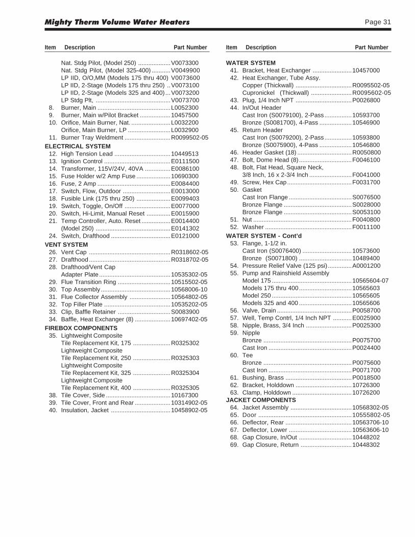
Mighty Therm Volume Water Heaters Page 31
Nat. Stdg Pilot, (Model 250) ...................V0073300Nat. Stdg Pilot, (Model 325-400) ...........V0049900LP IID, O/O,MM (Models 175 thru 400) V0073600LP IID, 2-Stage (Models 175 thru 250) ..V0073100LP IID, 2-Stage (Models 325 and 400) ...V0073200LP Stdg Plt, ............................................V0073700
8. Burner, Main ...........................................L00523009. Burner, Main w/Pilot Bracket ..................1045750010. Orifice, Main Burner, Nat. .......................L0032200
Orifice, Main Burner, LP .........................L003290011. Burner Tray Weldment ...........................R0099502-05
ELECTRICAL SYSTEM12. High Tension Lead .................................1044951313. Ignition Control .......................................E011150014. Transformer, 115V/24V, 40VA ...............E008610015. Fuse Holder w/2 Amp Fuse ....................1069030016. Fuse, 2 Amp ...........................................E008440017. Switch, Flow, Outdoor ............................E001300018. Fusible Link (175 thru 250) ....................E009940319. Switch, Toggle, On/Off ...........................E007700020. Switch, Hi-Limit, Manual Reset ..............E001590021. Temp Controller, Auto. Reset .................E0014400
(Model 250) ............................................E014130224. Switch, Drafthood ...................................E0121000
VENT SYSTEM26. Vent Cap ................................................R0318602-0527. Drafthood................................................R0318702-0528. Drafthood/Vent Cap
Adapter Plate ..........................................10535302-0529. Flue Transition Ring ...............................10515502-0530. Top Assembly .........................................10568006-1031. Flue Collector Assembly ........................10564802-0532. Top Filler Plate .......................................10535202-0533. Clip, Baffle Retainer ...............................S008390034. Baffle, Heat Exchanger (8) .....................10697402-05
FIREBOX COMPONENTS35. Lightweight Composite
Tile Replacement Kit, 175 ......................R0325302Lightweight CompositeTile Replacement Kit, 250 ......................R0325303Lightweight CompositeTile Replacement Kit, 325 ......................R0325304Lightweight CompositeTile Replacement Kit, 400 ......................R0325305
38. Tile Cover, Side ......................................1016730039. Tile Cover, Front and Rear .....................10314902-0540. Insulation, Jacket ...................................10458902-05
WATER SYSTEM41. Bracket, Heat Exchanger .......................1045700042. Heat Exchanger, Tube Assy.
Copper (Thickwall) .................................R0095502-05Cupronickel (Thickwall) ........................R0095602-05
43. Plug, 1/4 Inch NPT .................................P002680044. In/Out Header
Cast Iron (S0079100), 2-Pass................10593700Bronze (S0081700), 4-Pass ...................10546900
45. Return HeaderCast Iron (S0079200), 2-Pass................10593800Bronze (S0075900), 4-Pass ...................10546800
46. Header Gasket (18) ................................R005080047. Bolt, Dome Head (8) ...............................F004610048. Bolt, Flat Head, Square Neck,
3/8 Inch, 16 x 2-3/4 Inch .........................F004100049. Screw, Hex Cap......................................F003170050. Gasket
Cast Iron Flange .....................................S0076500Bronze Flange ........................................S0028000Bronze Flange ........................................S0053100
51. Nut ..........................................................F004080052. Washer ...................................................F0011100
WATER SYSTEM - Cont’d53. Flange, 1-1/2 in.
Cast Iron (S0076400) .............................10573600Bronze (S0071800) ...............................10489400
54. Pressure Relief Valve (125 psi) ..............A000120055. Pump and Rainshield Assembly
Model 175 ...............................................10565604-07Models 175 thru 400...............................10565603Model 250 ...............................................10565605Models 325 and 400 ...............................10565606
56. Valve, Drain ............................................P005870057. Well, Temp Contrl, 1/4 Inch NPT ...........E002590058. Nipple, Brass, 3/4 Inch ...........................P002530059. Nipple
Bronze ....................................................P0075700Cast Iron .................................................P0024400
60. TeeBronze ....................................................P0075600Cast Iron .................................................P0071700
61. Bushing, Brass .......................................P001850062. Bracket, Holddown .................................1072630063. Clamp, Holddown ...................................10726200
JACKET COMPONENTS64. Jacket Assembly ....................................10568302-0565. Door .......................................................10555802-0566. Deflector, Rear .......................................10563706-1067. Deflector, Lower .....................................10563606-1068. Gap Closure, In/Out ...............................1044820269. Gap Closure, Return ..............................10448302
Item Description Part Number Item Description Part Number
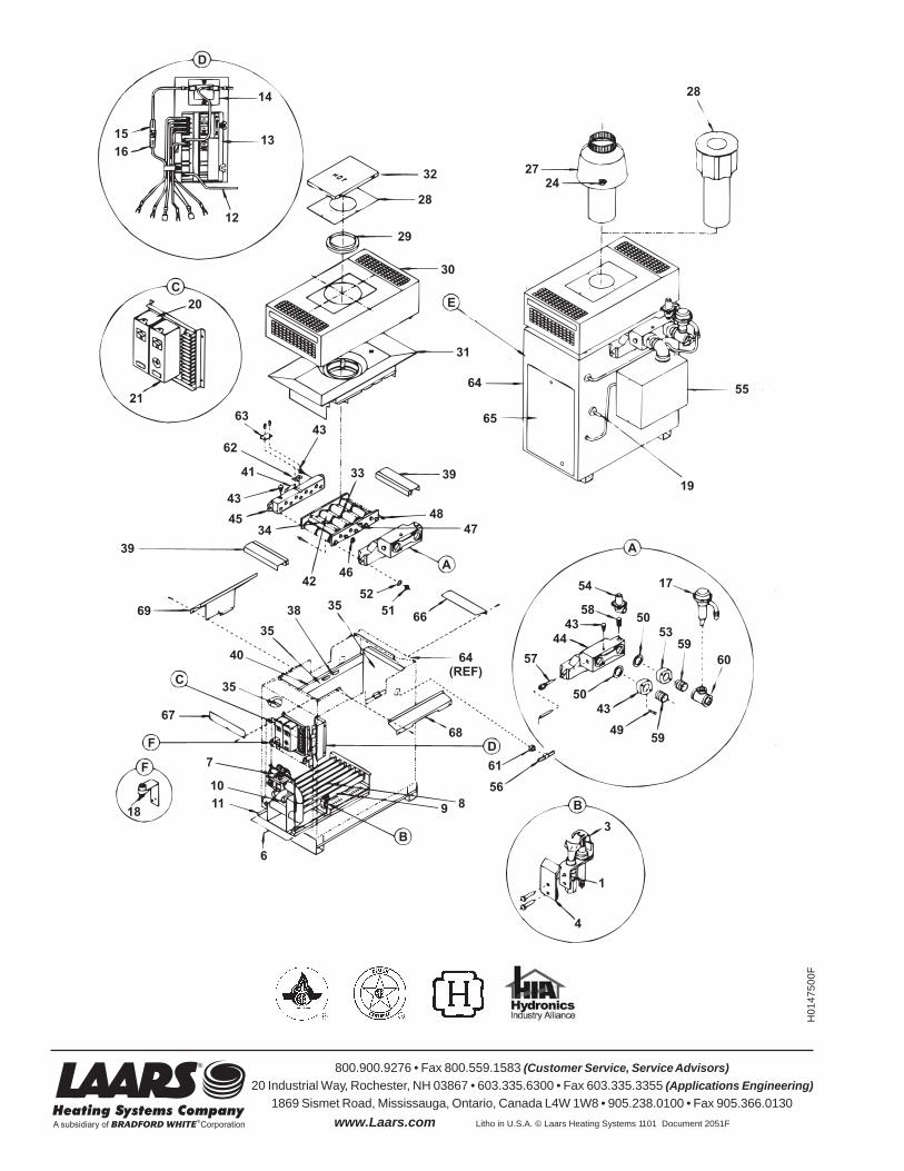
H0
14
75
00
F
800.900.9276 • Fax 800.559.1583 (Customer Service, Service Advisors)
20 Industrial Way, Rochester, NH 03867 • 603.335.6300 • Fax 603.335.3355 (Applications Engineering)
1869 Sismet Road, Mississauga, Ontario, Canada L4W 1W8 • 905.238.0100 • Fax 905.366.0130
www.Laars.com Litho in U.S.A. © Laars Heating Systems 1101 Document 2051F