operation and maintenance instructions zh series large
TRANSCRIPT
Operation and Maintenance Instructions ZH Series Large Bore Lathes Models GH-2680ZH; GH-26120ZH
Model GH-2680ZH shown
For ZH-Series Lathes Parts List and Electrical Diagrams, see document M-321860-1
JET
427 New Sanford Road LaVergne, Tennessee 37086 Part No. M-321860 Ph.: 800-274-6848 Revision C2 10/2017 www.jettools.com Copyright © 2017 JET
2
1.0 Warranty and Service JET warrants every product it sells against manufacturers’ defects. If one of our tools needs service or repair, please contact Technical Service by calling 1-800-274-6846, 8AM to 5PM CST, Monday through Friday.
Warranty Period The general warranty lasts for the time period specified in the literature included with your product or on the official JET branded website.
• JET products carry a limited warranty which varies in duration based upon the product. (See chart below) • Accessories carry a limited warranty of one year from the date of receipt. • Consumable items are defined as expendable parts or accessories expected to become inoperable within a
reasonable amount of use and are covered by a 90 day limited warranty against manufacturer’s defects.
Who is Covered This warranty covers only the initial purchaser of the product from the date of delivery.
What is Covered This warranty covers any defects in workmanship or materials subject to the limitations stated below. This warranty does not cover failures due directly or indirectly to misuse, abuse, negligence or accidents, normal wear-and-tear, improper repair, alterations or lack of maintenance. JET woodworking machinery is designed to be used with Wood. Use of these machines in the processing of metal, plastics, or other materials may void the warranty. The exceptions are acrylics and other natural items that are made specifically for wood turning.
Warranty Limitations Woodworking products with a Five Year Warranty that are used for commercial or industrial purposes default to a Two Year Warranty. Please contact Technical Service at 1-800-274-6846 for further clarification.
How to Get Technical Support Please contact Technical Service by calling 1-800-274-6846.Please note that you will be asked to provide proof of initial purchase when calling. If a product requires further inspection, the Technical Service representative will explain and assist with any additional action needed. JET has Authorized Service Centers located throughout the United States. For the name of an Authorized Service Center in your area call 1-800-274-6846 or use the Service Center Locator on the JET website.
More Information JET is constantly adding new products. For complete, up-to-date product information, check with your local distributor or visit the JET website.
How State Law Applies This warranty gives you specific legal rights, subject to applicable state law.
Limitations on This Warranty JET LIMITS ALL IMPLIED WARRANTIES TO THE PERIOD OF THE LIMITED WARRANTY FOR EACH PRODUCT. EXCEPT AS STATED HEREIN, ANY IMPLIED WARRANTIES OF MERCHANTABILITY AND FITNESS FOR A PARTICULAR PURPOSE ARE EXCLUDED. SOME STATES DO NOT ALLOW LIMITATIONS ON HOW LONG AN IMPLIED WARRANTY LASTS, SO THE ABOVE LIMITATION MAY NOT APPLY TO YOU. JET SHALL IN NO EVENT BE LIABLE FOR DEATH, INJURIES TO PERSONS OR PROPERTY, OR FOR INCIDENTAL, CONTINGENT, SPECIAL, OR CONSEQUENTIAL DAMAGES ARISING FROM THE USE OF OUR PRODUCTS. SOME STATES DO NOT ALLOW THE EXCLUSION OR LIMITATION OF INCIDENTAL OR CONSEQUENTIAL DAMAGES, SO THE ABOVE LIMITATION OR EXCLUSION MAY NOT APPLY TO YOU. JET sells through distributors only. The specifications listed in JET printed materials and on official JET website are given as general information and are not binding. JET reserves the right to effect at any time, without prior notice, those alterations to parts, fittings, and accessory equipment which they may deem necessary for any reason whatsoever. JET® branded products are not sold in Canada by JPW Industries, Inc.
Product Listing with Warranty Period 90 Days – Parts; Consumable items 1 Year – Motors; Machine Accessories 2 Year – Metalworking Machinery; Electric Hoists, Electric Hoist Accessories; Woodworking Machinery used for industrial or commercial purposes 5 Year – Woodworking Machinery Limited Lifetime – JET Parallel clamps; VOLT Series Electric Hoists; Manual Hoists; Manual Hoist Accessories; Shop Tools; Warehouse & Dock products; Hand Tools; Air Tools NOTE: JET is a division of JPW Industries, Inc. References in this document to JET also apply to JPW Industries, Inc., or any of its successors in interest to the JET brand.

3
2.0 Table of Contents 1.0 Warranty and Service ..................................................................................................................................... 2 2.0 Table of Contents ........................................................................................................................................... 3 3.0 IMPORTANT SAFETY INSTRUCTIONS ....................................................................................................... 4 4.0 Specifications ................................................................................................................................................. 6 5.0 Dimensions and mounting hole centers ......................................................................................................... 8 6.0 General description and nomenclature .......................................................................................................... 9 7.0 Unpacking .................................................................................................................................................... 11
7.1Contents of the Shipping Container ........................................................................................................... 11 8.0 Installation .................................................................................................................................................... 12
8.1 Leveling the lathe ..................................................................................................................................... 12 8.2 Completing installation ............................................................................................................................. 12 8.3 Chuck Preparation .................................................................................................................................... 13 8.4 Break-In Period ........................................................................................................................................ 13
9.0 Maintenance/Lubrication ............................................................................................................................... 14 9.1 Coolant Preparation ................................................................................................................................. 16
10.0 Electrical Connections ................................................................................................................................ 16 10.1 Conversion to 460 Volt Operation............................................................................................................ 17
11.0 Basic Controls ............................................................................................................................................ 18 12.0 Operation ................................................................................................................................................... 20
12.1 Tool Setup .............................................................................................................................................. 21 12.2 Spindle Speed ........................................................................................................................................ 21 12.3 Feed and Thread Selection .................................................................................................................... 21 12.4 Thread Cutting ........................................................................................................................................ 22
13.0 Adjustments ............................................................................................................................................... 22 13.1 Chuck Jaw Reversal ............................................................................................................................... 22 13.2 Gib Adjustments ..................................................................................................................................... 22 13.3 Tailstock Adjustments ............................................................................................................................ 23 13.4 Gap Section ............................................................................................................................................ 23 13.5 Belt Adjustment and Replacement ............................................................................................................ 24 13.6 Brake Strap ............................................................................................................................................ 24 13.7 Friction Clutch Adjustment ..................................................................................................................... 24 13.8 Aligning Tailstock to Headstock ............................................................................................................. 25 13.9 Spindle Bearings .................................................................................................................................... 25 13.10 Speed Control ...................................................................................................................................... 25 13.11 Lead Screw .......................................................................................................................................... 26 13.12 Apron Feed Clutch ............................................................................................................................... 26 13.13 Tool Post .............................................................................................................................................. 26 13.14 Cross Slide Nut Adjustment ................................................................................................................. 27 13.15 Shear Pin Replacement ....................................................................................................................... 27 13.16 Steady Rest Adjustment ....................................................................................................................... 27 13.17 Follow Rest Adjustment ........................................................................................................................ 28
14.0 Troubleshooting the ZH Series Lathes ....................................................................................................... 29 15.0 Lubrication Schedule and General Maintenance ....................................................................................... 30 16.0 Reference Tables ....................................................................................................................................... 31
16.1Inch Lead And Feed ................................................................................................................................. 31 16.2Special Inch Lead And Feed .................................................................................................................... 32 16.3 Speed Selection Lever Positions ............................................................................................................ 33
17.0 Electrical – 230 volt to 460 volt Conversion ............................................................................................... 33 18.0 Change Gear Diagram ............................................................................................................................... 34
4
3.0 IMPORTANT SAFETY INSTRUCTIONS 1. Read and understand the entire owner’s manual before attempting assembly or operation.
2. Read and understand the warnings posted on the machine and in this manual. Failure to comply with all of these warnings may cause serious injury.
3. Replace the warning labels if they become obscured or removed.
4. This lathe is designed and intended for use by properly trained and experienced personnel only. If you are not familiar with the proper and safe operation of a lathe, do not use until proper training and knowledge have been obtained.
5. Do not use this lathe for other than its intended use. If used for other purposes, JET disclaims any real or implied warranty and holds itself harmless from any injury that may result from that use.
6. Always wear approved safety glasses/face shields while using this lathe. Everyday eyeglasses only have impact resistant lenses; they are not safety glasses.
7. Before operating this lathe, remove tie, rings, watches and other jewelry, and roll sleeves up past the elbows. Remove all loose clothing and confine long hair. Non-slip footwear or anti-skid floor strips are recommended. Do not wear gloves.
8. Wear ear protectors (plugs or muffs) during extended periods of operation.
9. CALIFORNIA PROPOSITION 65 WARNING: This product contains chemicals known to the State of California to cause cancer, or birth defects or other reproductive harm.
10. This product, when used for welding, cutting, or working with metal, produces fumes, gases, or dusts which contain chemicals known to the State of California to cause birth defects and, in some cases, cancer. (California Health and Safety Code Section 25249.5 et seq.)
11. Do not operate this machine while tired or under the influence of drugs, alcohol or any medication.
12. Make certain the switch is in the OFF position before connecting the machine to the power supply.
13. Make certain the machine is properly grounded.
14. Make all machine adjustments or maintenance with the machine unplugged from the power source.
15. Remove adjusting keys and wrenches. Form a habit of checking to see that keys and adjusting wrenches are removed from the machine before turning it on.
16. Keep safety guards in place at all times when the machine is in use. If removed for maintenance purposes, use extreme caution and replace the guards immediately after maintenance is complete.
17. Check damaged parts. Before further use of the machine, a guard or other part that is damaged should be carefully checked to determine that it will operate properly and perform its intended function. Check for alignment of moving parts, binding of moving parts, breakage of parts, mounting and any other conditions that may affect its operation. A guard or other part that is damaged should be properly repaired or replaced.
18. Provide for adequate space surrounding work area and non-glare, overhead lighting.
19. Keep the floor around the machine clean and free of scrap material, oil and grease.
20. Keep visitors a safe distance from the work area. Keep children away.
21. Make your workshop child proof with padlocks, master switches or by removing starter keys.
22. Give your work undivided attention. Looking around, carrying on a conversation and “horse-play” are careless acts that can result in serious injury.
23. Maintain a balanced stance at all times so that you do not fall or lean against moving parts. Do not overreach or use excessive force to perform any machine operation. Never force the cutting action.
24. Maintain a balanced stance at all times so that you do not fall or lean against moving parts. Do not overreach or use excessive force to perform any machine operation. Never force the cutting action.
25. Use the right tool at the correct speed and feed rate. Do not force a tool or attachment to do a job for which it was not designed. The right tool will do the job better and more safely.
5
26. Use recommended accessories; improper accessories may be hazardous.
27. Maintain tools with care. Keep cutting tools sharp and clean for the best and safest performance. Follow instructions for lubricating and changing accessories.
28. Do not attempt to adjust or remove tools during operation.
29. Never stop a rotating chuck or workpiece with your hands.
30. Choose a low spindle speed when working unbalanced workpieces, and for threading and tapping operations.
31. Do not exceed the maximum speed of the workholding device.
32. Do not exceed the clamping capacity of the chuck.
33. Workpieces longer than 3 times the chucking diameter must be supported by the tailstock or a steady rest.
34. Avoid small chuck diameters with large turning diameters.
35. Avoid short chucking lengths and small chucking contact.
36. Turn off the machine and disconnect from power before cleaning. Use a brush to remove shavings or debris — do not use your hands.
37. Do not stand on the machine. Serious injury could occur if the machine tips over.
38. Never leave the machine running unattended. Turn the power off and do not leave the machine until moving parts come to a complete stop.
39. Remove loose items and unnecessary work pieces from the area before starting the machine.
40. Do not operate the lathe in flammable or explosive environments. Do not use in a damp environment or expose to rain.
Familiarize yourself with the following safety notices used in this manual:
This means that if precautions are not heeded, it may result in minor injury and/or possible machine damage.
This means that if precautions are not heeded, it may result in serious injury or possibly even death.
6
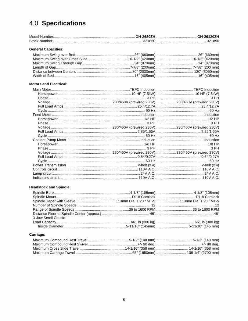
4.0 Specifications Model Number................................................................................ GH-2680ZH ......................................... GH-26120ZH Stock Number ....................................................................................... 321860 .................................................. 321890 General Capacities:
Maximum Swing over Bed ......................................................... 26” (660mm) ......................................... 26” (660mm) Maximum Swing over Cross Slide ....................................... 16-1/2” (420mm) ................................... 16-1/2” (420mm) Maximum Swing Through Gap .................................................. 34” (870mm) ......................................... 34” (870mm) Length of Gap ........................................................................ 7-7/8” (200mm) .................................... 7-7/8” (200 mm) Distance between Centers ...................................................... 80” (2030mm) ..................................... 120” (3050mm) Width of Bed .............................................................................. 16” (405mm) ......................................... 16” (405mm)
Motors and Electrical:
Main Motor.............................................................................TEFC Induction ..................................... TEFC Induction Horsepower ....................................................................... 10 HP (7.5kW) ...................................... 10 HP (7.5kW) Phase ............................................................................................... 3 PH ...................................................... 3 PH Voltage ............................................................ 230/460V (prewired 230V) .................... 230/460V (prewired 230V) Full Load Amps ........................................................................ 25.4/12.7A .............................................25.4/12.7A Cycle ............................................................................................... 60 Hz .................................................... 60 Hz Feed Motor ...................................................................................... Induction ............................................... Induction Horsepower ................................................................................... 1/2 HP ................................................... 1/2 HP Phase ............................................................................................... 3 PH ...................................................... 3 PH Voltage ............................................................ 230/460V (prewired 230V) .................... 230/460V (prewired 230V) Full Load Amps ........................................................................ 2.85/1.65A .............................................2.85/1.65A Cycle ............................................................................................... 60 Hz .................................................... 60 Hz Coolant Pump Motor ........................................................................ Induction ............................................... Induction Horsepower ................................................................................... 1/8 HP ................................................... 1/8 HP Phase ............................................................................................... 3 PH ...................................................... 3 PH Voltage ............................................................ 230/460V (prewired 230V) .................... 230/460V (prewired 230V) Full Load Amps ........................................................................ 0.54/0.27A .............................................0.54/0.27A Cycle ............................................................................................... 60 Hz .................................................... 60 Hz Power Transmission ..................................................................... v-belt (x 4) ............................................. v-belt (x 4) Controls circuit ............................................................................... 110V A.C. ..............................................110V A.C. Lamp circuit ..................................................................................... 24V A.C. ...............................................24V A.C. Indicators circuit ............................................................................. 110V A.C. ............................................. 110V A.C.
Headstock and Spindle:
Spindle Bore .......................................................................... 4-1/8” (105mm) ..................................... 4-1/8” (105mm) Spindle Mount.......................................................................... D1-8 Camlock ....................................... D1-8 Camlock Spindle Taper with Sleeve ....................................... 113mm Dia. 1:20 / MT-5 ....................... 113mm Dia. 1:20 / MT-5 Number of Spindle Speeds ........................................................................ 12 .......................................................... 12 Range of Spindle Speeds .....................................................36 to 1600 RPM .................................... 36 to 1600 RPM Distance Floor to Spindle Center (approx.) .............................................. 46” ......................................................... 46” 3-Jaw Scroll Chuck: Load Capacity........................................................................ 661 lb (300 kg) ...................................... 661 lb (300 kg) Inside Diameter ............................................................ 5-11/16” (145mm) ................................ 5-11/16” (145 mm)
Carriage: Maximum Compound Rest Travel ........................................ 5-1/2” (140 mm) .................................... 5-1/2” (140 mm) Maximum Compound Rest Swivel ................................................ +/- 90 deg. ............................................. +/- 90 deg. Maximum Cross Slide Travel ............................................ 14-1/16” (358 mm) ................................ 14-1/16” (358 mm) Maximum Carriage Travel ....................................................... 65” (1650mm) .............................. 106-1/4” (2700 mm)
7
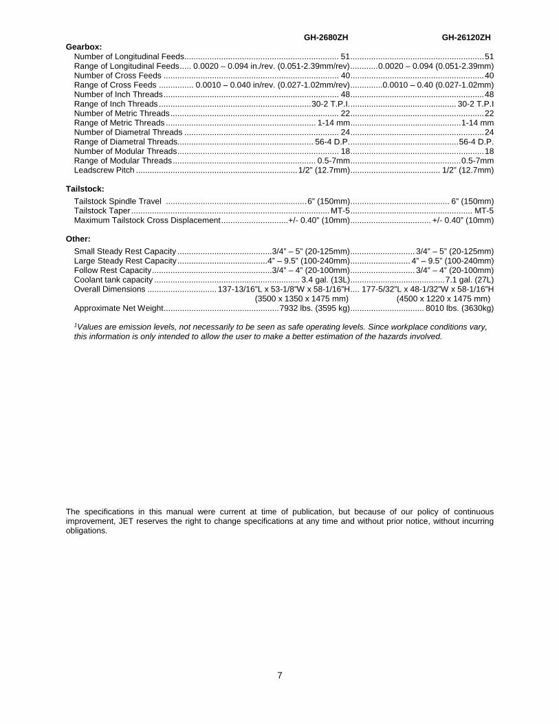
GH-2680ZH GH-26120ZH Gearbox:
Number of Longitudinal Feeds................................................................... 51 .......................................................... 51 Range of Longitudinal Feeds ..... 0.0020 – 0.094 in./rev. (0.051-2.39mm/rev) ............ 0.0020 – 0.094 (0.051-2.39mm) Number of Cross Feeds ............................................................................ 40 .......................................................... 40 Range of Cross Feeds ............... 0.0010 – 0.040 in/rev. (0.027-1.02mm/rev) .............. 0.0010 – 0.40 (0.027-1.02mm) Number of Inch Threads ............................................................................ 48 .......................................................... 48 Range of Inch Threads .................................................................. 30-2 T.P.I. .............................................. 30-2 T.P.I Number of Metric Threads ......................................................................... 22 .......................................................... 22 Range of Metric Threads ................................................................. 1-14 mm ................................................ 1-14 mm Number of Diametral Threads ................................................................... 24 .......................................................... 24 Range of Diametral Threads........................................................... 56-4 D.P. ............................................... 56-4 D.P. Number of Modular Threads ...................................................................... 18 .......................................................... 18 Range of Modular Threads .............................................................. 0.5-7mm ................................................ 0.5-7mm Leadscrew Pitch ...................................................................... 1/2” (12.7mm) ....................................... 1/2” (12.7mm)
Tailstock:
Tailstock Spindle Travel ............................................................. 6” (150mm) ........................................... 6” (150mm) Tailstock Taper ...................................................................................... MT-5 ..................................................... MT-5 Maximum Tailstock Cross Displacement ............................. +/- 0.40” (10mm) ................................... +/- 0.40” (10mm)
Other:
Small Steady Rest Capacity ......................................... 3/4” – 5” (20-125mm) ............................ 3/4” – 5” (20-125mm) Large Steady Rest Capacity ....................................... 4” – 9.5” (100-240mm) .......................... 4” – 9.5” (100-240mm) Follow Rest Capacity .................................................... 3/4” – 4” (20-100mm) ............................ 3/4” – 4” (20-100mm) Coolant tank capacity ............................................................... 3.4 gal. (13L) ......................................... 7.1 gal. (27L) Overall Dimensions .............................. 137-13/16”L x 53-1/8”W x 58-1/16”H .... 177-5/32”L x 48-1/32”W x 58-1/16”H (3500 x 1350 x 1475 mm) (4500 x 1220 x 1475 mm) Approximate Net Weight .................................................. 7932 lbs. (3595 kg) ................................ 8010 lbs. (3630kg) 1Values are emission levels, not necessarily to be seen as safe operating levels. Since workplace conditions vary, this information is only intended to allow the user to make a better estimation of the hazards involved.
The specifications in this manual were current at time of publication, but because of our policy of continuous improvement, JET reserves the right to change specifications at any time and without prior notice, without incurring obligations.
8
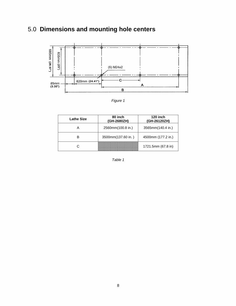
5.0 Dimensions and mounting hole centers
Figure 1
Lathe Size 80 inch(GH-2680ZH)
120 inch(GH-26120ZH)
A 2560mm(100.8 in.) 3565mm(140.4 in.)
B 3500mm(137.60 in. ) 4500mm (177.2 in.)
C 1721.5mm (67.8 in)
Table 1
9
6.0 General description and nomenclature
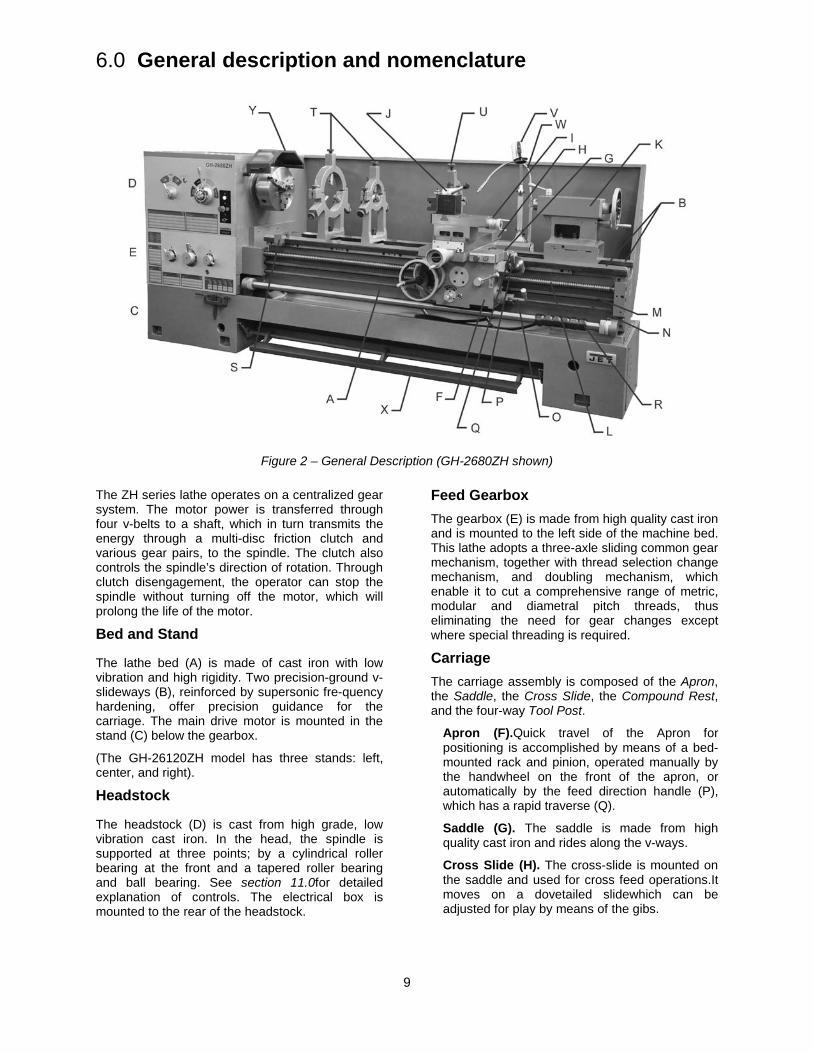
Figure 2 – General Description (GH-2680ZH shown)
The ZH series lathe operates on a centralized gear system. The motor power is transferred through four v-belts to a shaft, which in turn transmits the energy through a multi-disc friction clutch and various gear pairs, to the spindle. The clutch also controls the spindle’s direction of rotation. Through clutch disengagement, the operator can stop the spindle without turning off the motor, which will prolong the life of the motor.
Bed and Stand
The lathe bed (A) is made of cast iron with low vibration and high rigidity. Two precision-ground v-slideways (B), reinforced by supersonic fre-quency hardening, offer precision guidance for the carriage. The main drive motor is mounted in the stand (C) below the gearbox.
(The GH-26120ZH model has three stands: left, center, and right).
Headstock
The headstock (D) is cast from high grade, low vibration cast iron. In the head, the spindle is supported at three points; by a cylindrical roller bearing at the front and a tapered roller bearing and ball bearing. See section 11.0for detailed explanation of controls. The electrical box is mounted to the rear of the headstock.
Feed Gearbox The gearbox (E) is made from high quality cast iron and is mounted to the left side of the machine bed. This lathe adopts a three-axle sliding common gear mechanism, together with thread selection change mechanism, and doubling mechanism, which enable it to cut a comprehensive range of metric, modular and diametral pitch threads, thus eliminating the need for gear changes except where special threading is required.
Carriage The carriage assembly is composed of the Apron, the Saddle, the Cross Slide, the Compound Rest, and the four-way Tool Post.
Apron (F).Quick travel of the Apron for positioning is accomplished by means of a bed-mounted rack and pinion, operated manually by the handwheel on the front of the apron, or automatically by the feed direction handle (P), which has a rapid traverse (Q).
Saddle (G). The saddle is made from high quality cast iron and rides along the v-ways.
Cross Slide (H). The cross-slide is mounted on the saddle and used for cross feed operations.It moves on a dovetailed slidewhich can be adjusted for play by means of the gibs.
10
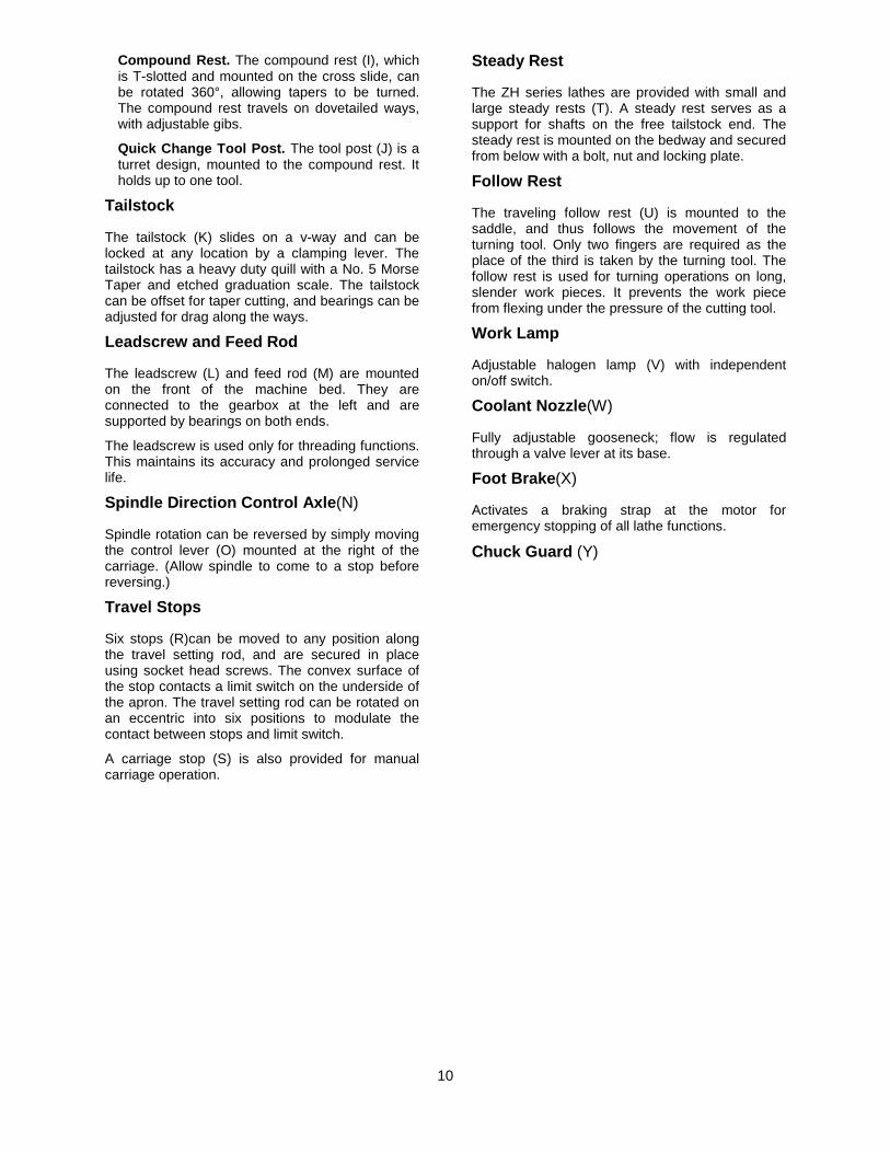
Compound Rest. The compound rest (I), which is T-slotted and mounted on the cross slide, can be rotated 360°, allowing tapers to be turned. The compound rest travels on dovetailed ways, with adjustable gibs.
Quick Change Tool Post. The tool post (J) is a turret design, mounted to the compound rest. It holds up to one tool.
Tailstock
The tailstock (K) slides on a v-way and can be locked at any location by a clamping lever. The tailstock has a heavy duty quill with a No. 5 Morse Taper and etched graduation scale. The tailstock can be offset for taper cutting, and bearings can be adjusted for drag along the ways.
Leadscrew and Feed Rod
The leadscrew (L) and feed rod (M) are mounted on the front of the machine bed. They are connected to the gearbox at the left and are supported by bearings on both ends.
The leadscrew is used only for threading functions. This maintains its accuracy and prolonged service life.
Spindle Direction Control Axle(N)
Spindle rotation can be reversed by simply moving the control lever (O) mounted at the right of the carriage. (Allow spindle to come to a stop before reversing.)
Travel Stops
Six stops (R)can be moved to any position along the travel setting rod, and are secured in place using socket head screws. The convex surface of the stop contacts a limit switch on the underside of the apron. The travel setting rod can be rotated on an eccentric into six positions to modulate the contact between stops and limit switch.
A carriage stop (S) is also provided for manual carriage operation.
Steady Rest
The ZH series lathes are provided with small and large steady rests (T). A steady rest serves as a support for shafts on the free tailstock end. The steady rest is mounted on the bedway and secured from below with a bolt, nut and locking plate.
Follow Rest
The traveling follow rest (U) is mounted to the saddle, and thus follows the movement of the turning tool. Only two fingers are required as the place of the third is taken by the turning tool. The follow rest is used for turning operations on long, slender work pieces. It prevents the work piece from flexing under the pressure of the cutting tool.
Work Lamp
Adjustable halogen lamp (V) with independent on/off switch.
Coolant Nozzle(W)
Fully adjustable gooseneck; flow is regulated through a valve lever at its base.
Foot Brake(X)
Activates a braking strap at the motor for emergency stopping of all lathe functions.
Chuck Guard (Y)
11
7.0 Unpacking Open shipping container and check for shipping damage. Report any damage immediately to your distributor and shipping agent. Do not discard any shipping material until the Latheis set up and running properly.
Compare the contents of your container with the following parts list to make sure all parts are intact. Missing parts, if any, should be reported to your distributor. Read the instruction manual thoroughly for set up, maintenance and safety instructions.
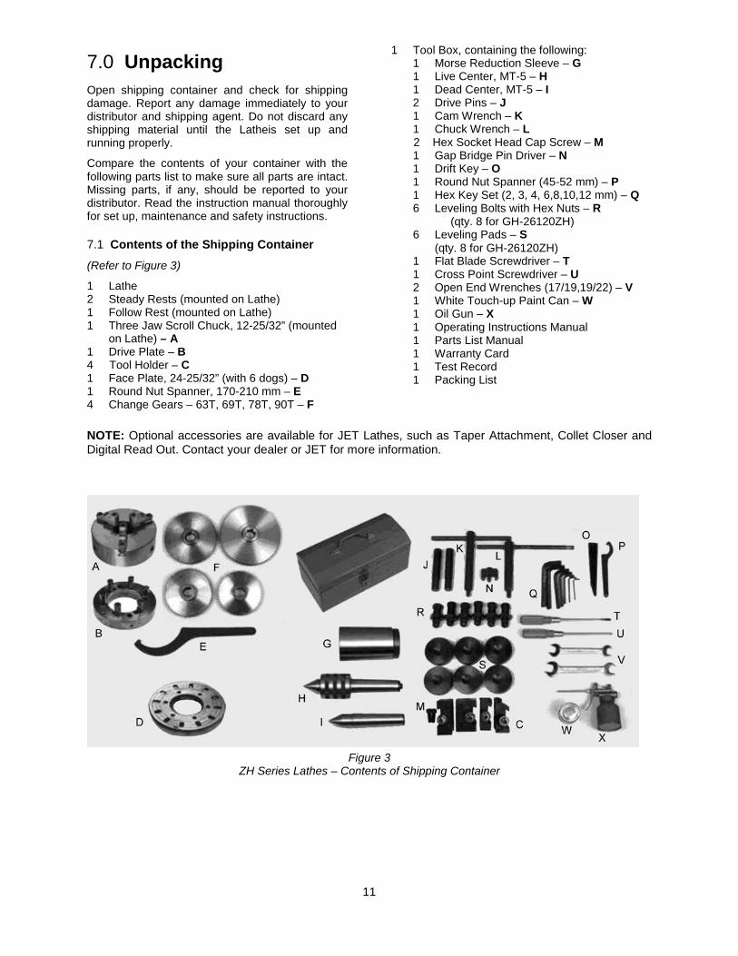
7.1 Contents of the Shipping Container (Refer to Figure 3)
1 Lathe 2 Steady Rests (mounted on Lathe) 1 Follow Rest (mounted on Lathe) 1 Three Jaw Scroll Chuck, 12-25/32” (mounted
on Lathe) – A 1 Drive Plate – B 4 Tool Holder – C 1 Face Plate, 24-25/32” (with 6 dogs) – D 1 Round Nut Spanner, 170-210 mm – E 4 Change Gears – 63T, 69T, 78T, 90T – F
1 Tool Box, containing the following: 1 Morse Reduction Sleeve – G 1 Live Center, MT-5 – H 1 Dead Center, MT-5 – I 2 Drive Pins – J 1 Cam Wrench – K 1 Chuck Wrench – L 2 Hex Socket Head Cap Screw – M 1 Gap Bridge Pin Driver – N 1 Drift Key – O 1 Round Nut Spanner (45-52 mm) – P 1 Hex Key Set (2, 3, 4, 6,8,10,12 mm) – Q 6 Leveling Bolts with Hex Nuts – R (qty. 8 for GH-26120ZH) 6 Leveling Pads – S (qty. 8 for GH-26120ZH) 1 Flat Blade Screwdriver – T 1 Cross Point Screwdriver – U 2 Open End Wrenches (17/19,19/22) – V 1 White Touch-up Paint Can – W 1 Oil Gun – X
1 Operating Instructions Manual 1 Parts List Manual 1 Warranty Card
1 Test Record 1 Packing List
NOTE: Optional accessories are available for JET Lathes, such as Taper Attachment, Collet Closer and Digital Read Out. Contact your dealer or JET for more information.
Figure 3
ZH Series Lathes – Contents of Shipping Container
8.0 Installation 1. Finish removing all crate material from around
lathe.
2. Unbolt lathe from shipping pallet.
3. Choose a location for the lathe that is dry and has sufficient illumination.
4. Allow enough room to service the lathe on all four sides, and to load and off-load work pieces. In addition, if bar work is to be performed, allow enough space for stock to extend out the headstock end. If used in production operations, leave enough space for stacking unfinished and finished parts.
5. The foundation must be solid to support the weight of the machine and prevent vibration, preferably a solid concrete floor.
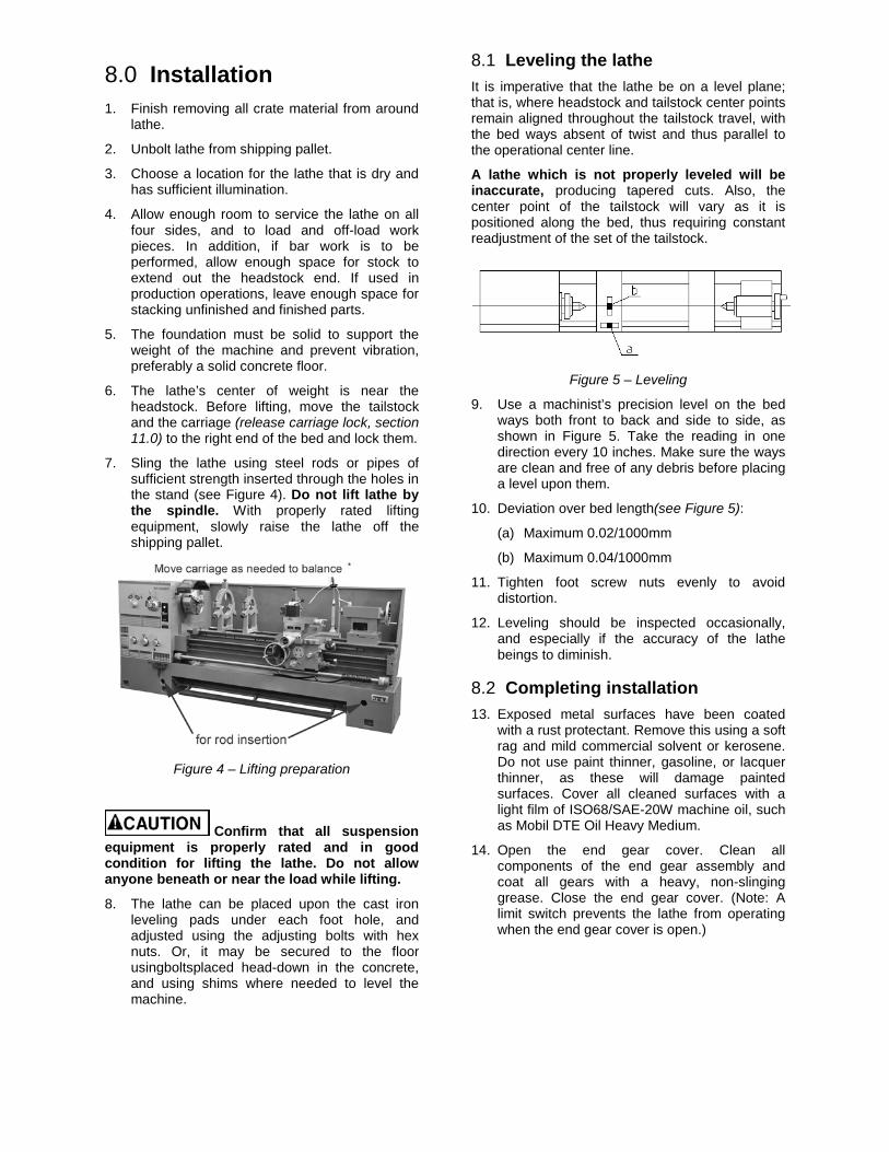
6. The lathe’s center of weight is near the headstock. Before lifting, move the tailstock and the carriage (release carriage lock, section 11.0) to the right end of the bed and lock them.
7. Sling the lathe using steel rods or pipes of sufficient strength inserted through the holes in the stand (see Figure 4). Do not lift lathe by the spindle. With properly rated lifting equipment, slowly raise the lathe off the shipping pallet.
Figure 4 – Lifting preparation
Confirm that all suspension equipment is properly rated and in good condition for lifting the lathe. Do not allow anyone beneath or near the load while lifting.
8. The lathe can be placed upon the cast iron leveling pads under each foot hole, and adjusted using the adjusting bolts with hex nuts. Or, it may be secured to the floor usingboltsplaced head-down in the concrete, and using shims where needed to level the machine.
8.1 Leveling the lathe It is imperative that the lathe be on a level plane; that is, where headstock and tailstock center points remain aligned throughout the tailstock travel, with the bed ways absent of twist and thus parallel to the operational center line.
A lathe which is not properly leveled will be inaccurate, producing tapered cuts. Also, the center point of the tailstock will vary as it is positioned along the bed, thus requiring constant readjustment of the set of the tailstock.
Figure 5 – Leveling
9. Use a machinist’s precision level on the bed ways both front to back and side to side, as shown in Figure 5. Take the reading in one direction every 10 inches. Make sure the ways are clean and free of any debris before placing a level upon them.
10. Deviation over bed length(see Figure 5):
(a) Maximum 0.02/1000mm
(b) Maximum 0.04/1000mm
11. Tighten foot screw nuts evenly to avoid distortion.
12. Leveling should be inspected occasionally, and especially if the accuracy of the lathe beings to diminish.
8.2 Completing installation 13. Exposed metal surfaces have been coated
with a rust protectant. Remove this using a soft rag and mild commercial solvent or kerosene. Do not use paint thinner, gasoline, or lacquer thinner, as these will damage painted surfaces. Cover all cleaned surfaces with a light film of ISO68/SAE-20W machine oil, such as Mobil DTE Oil Heavy Medium.
14. Open the end gear cover. Clean all components of the end gear assembly and coat all gears with a heavy, non-slinging grease. Close the end gear cover. (Note: A limit switch prevents the lathe from operating when the end gear cover is open.)
13
8.3 Chuck Preparation
Read and understand all directions for chuck preparation. Failure to comply may cause serious injury and/or damage to the lathe.
The three-jaw scroll chuck is shipped pre-installed on the lathe. It can be used for clamping cylindrical, triangular and hexagonal stock, and has reversible jaws.
Note: An optional 4-jaw chuck is available (part no. ZH-2504). See your dealer to order.
Use an assistant or hoist to help remove a chuck.
Before removing a chuck, place a flat piece of thick plywood across the bedways under the chuck to prevent damage to the bedways should the chuck fall from your hands. Alternatively, many users make a wood chuck cradle that sits atop the ways and accepts the specific diameter of chuck. Figure 6 shows an example.
Figure 6 – Chuck cradle (not included)
To remove a chuck from the spindle:
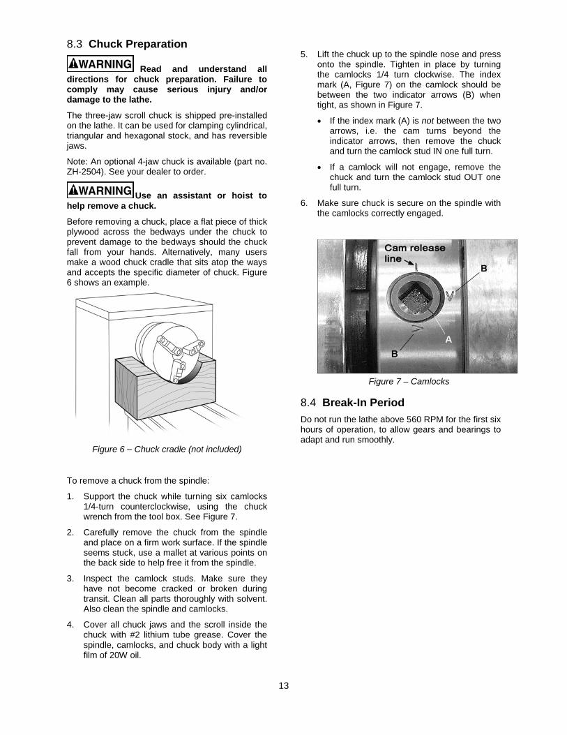
1. Support the chuck while turning six camlocks 1/4-turn counterclockwise, using the chuck wrench from the tool box. See Figure 7.
2. Carefully remove the chuck from the spindle and place on a firm work surface. If the spindle seems stuck, use a mallet at various points on the back side to help free it from the spindle.
3. Inspect the camlock studs. Make sure they have not become cracked or broken during transit. Clean all parts thoroughly with solvent. Also clean the spindle and camlocks.
4. Cover all chuck jaws and the scroll inside the chuck with #2 lithium tube grease. Cover the spindle, camlocks, and chuck body with a light film of 20W oil.
5. Lift the chuck up to the spindle nose and press onto the spindle. Tighten in place by turning the camlocks 1/4 turn clockwise. The index mark (A, Figure 7) on the camlock should be between the two indicator arrows (B) when tight, as shown in Figure 7.
• If the index mark (A) is not between the two arrows, i.e. the cam turns beyond the indicator arrows, then remove the chuck and turn the camlock stud IN one full turn.
• If a camlock will not engage, remove the chuck and turn the camlock stud OUT one full turn.
6. Make sure chuck is secure on the spindle with the camlocks correctly engaged.
Figure 7 – Camlocks
8.4 Break-In Period Do not run the lathe above 560 RPM for the first six hours of operation, to allow gears and bearings to adapt and run smoothly.
14
9.0 Maintenance/Lubrication
Lathe must be serviced at all lubrication points and all reservoirs filled to operating level before the lathe is put into service. Failure to comply may cause serious damage to the lathe.
The ZH series lathe is shipped with oil in the reservoirs. Coolant is not included.
Use clean lubricants and check levels often, including before each working shift. To ensure proper lubrication, oil levels should not be less than the center of the oil sight glass. Try not to overfill, as this may cause leakage.
A chart is supplied in section 15.0 for quick reference to all lubrication points.
Unless specified otherwise, the lubrication points require a non-detergent, ISO 68, SAE 20W oil. The recommended brand for this lathe is Mobil DTE® Oil Heavy Medium.
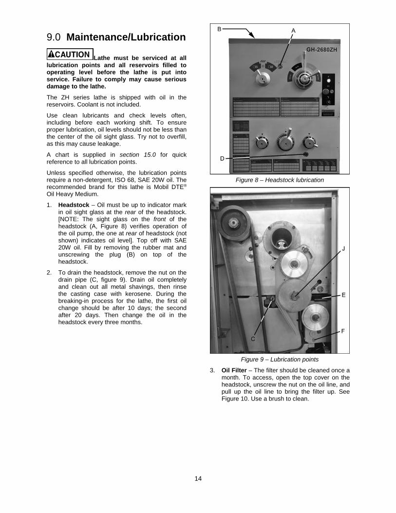
1. Headstock – Oil must be up to indicator mark in oil sight glass at the rear of the headstock. [NOTE: The sight glass on the front of the headstock (A, Figure 8) verifies operation of the oil pump, the one at rear of headstock (not shown) indicates oil level]. Top off with SAE 20W oil. Fill by removing the rubber mat and unscrewing the plug (B) on top of the headstock.
2. To drain the headstock, remove the nut on the drain pipe (C, figure 9). Drain oil completely and clean out all metal shavings, then rinse the casting case with kerosene. During the breaking-in process for the lathe, the first oil change should be after 10 days; the second after 20 days. Then change the oil in the headstock every three months.
Figure 8 – Headstock lubrication
Figure 9 – Lubrication points
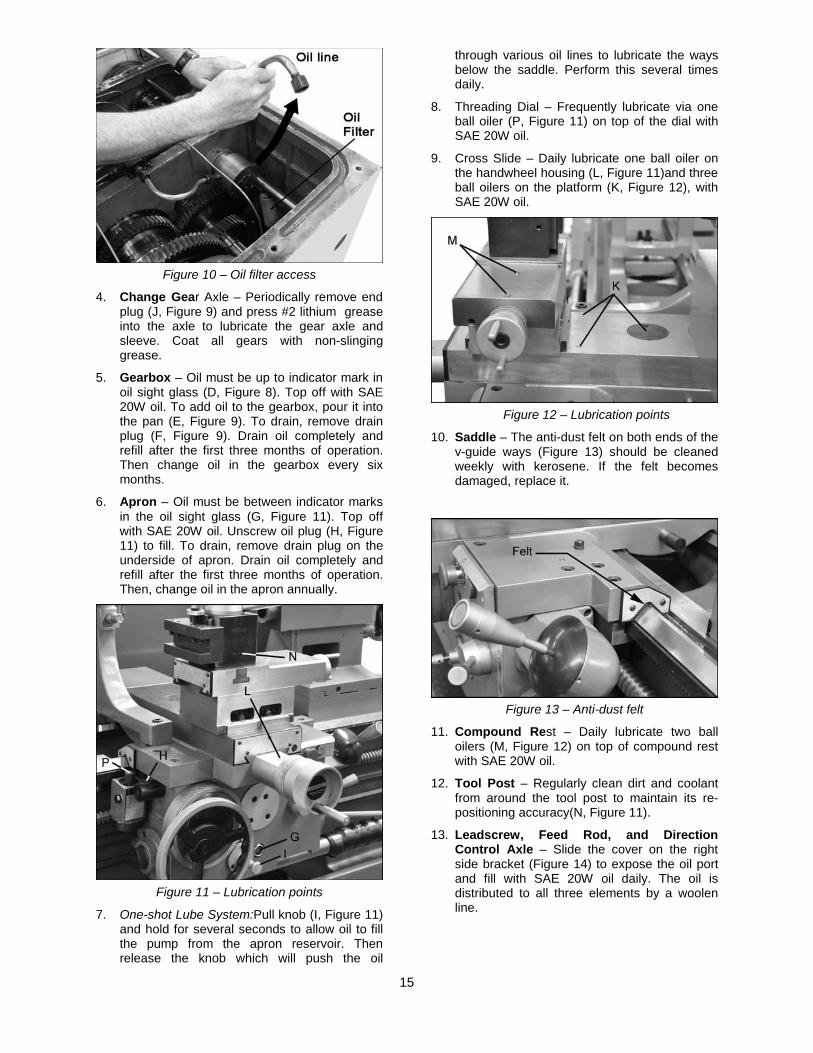
3. Oil Filter – The filter should be cleaned once a month. To access, open the top cover on the headstock, unscrew the nut on the oil line, and pull up the oil line to bring the filter up. See Figure 10. Use a brush to clean.
15
Figure 10 – Oil filter access
4. Change Gear Axle – Periodically remove end plug (J, Figure 9) and press #2 lithium grease into the axle to lubricate the gear axle and sleeve. Coat all gears with non-slinging grease.
5. Gearbox – Oil must be up to indicator mark in oil sight glass (D, Figure 8). Top off with SAE 20W oil. To add oil to the gearbox, pour it into the pan (E, Figure 9). To drain, remove drain plug (F, Figure 9). Drain oil completely and refill after the first three months of operation. Then change oil in the gearbox every six months.
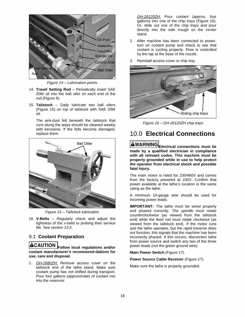
6. Apron – Oil must be between indicator marks in the oil sight glass (G, Figure 11). Top off with SAE 20W oil. Unscrew oil plug (H, Figure 11) to fill. To drain, remove drain plug on the underside of apron. Drain oil completely and refill after the first three months of operation. Then, change oil in the apron annually.
Figure 11 – Lubrication points
7. One-shot Lube System:Pull knob (I, Figure 11) and hold for several seconds to allow oil to fill the pump from the apron reservoir. Then release the knob which will push the oil
through various oil lines to lubricate the ways below the saddle. Perform this several times daily.
8. Threading Dial – Frequently lubricate via one ball oiler (P, Figure 11) on top of the dial with SAE 20W oil.
9. Cross Slide – Daily lubricate one ball oiler on the handwheel housing (L, Figure 11)and three ball oilers on the platform (K, Figure 12), with SAE 20W oil.
Figure 12 – Lubrication points
10. Saddle – The anti-dust felt on both ends of the v-guide ways (Figure 13) should be cleaned weekly with kerosene. If the felt becomes damaged, replace it.
Figure 13 – Anti-dust felt
11. Compound Rest – Daily lubricate two ball oilers (M, Figure 12) on top of compound rest with SAE 20W oil.
12. Tool Post – Regularly clean dirt and coolant from around the tool post to maintain its re-positioning accuracy(N, Figure 11).
13. Leadscrew, Feed Rod, and Direction Control Axle – Slide the cover on the right side bracket (Figure 14) to expose the oil port and fill with SAE 20W oil daily. The oil is distributed to all three elements by a woolen line.
16
Figure 14 – Lubrication points
14. Travel Setting Rod – Periodically insert SAE 20W oil into the ball oiler on each end of the rod (Figure 9).
15. Tailstock – Daily lubricate two ball oilers (Figure 15) on top of tailstock with SAE 20W oil.
The anti-dust felt beneath the tailstock that runs along the ways should be cleaned weekly with kerosene. If the felts become damaged, replace them.
Figure 15 – Tailstock lubrication
16. V-Belts – Regularly check and adjust the tightness of the v-belts to prolong their service life. See section 13.5.
9.1 Coolant Preparation
Follow local regulations and/or coolant manufacturer’s recommend-dations for use, care and disposal.
1. GH-2680ZH: Remove access cover on the tailstock end of the lathe stand. Make sure coolant pump has not shifted during transport. Pour four gallons (approximate) of coolant mix into the reservoir.
GH-26120ZH: Pour coolant (approx. four gallons) into one of the chip trays (Figure 16). Or, slide out one of the chip trays and pour directly into the side trough on the center stand.
2. After machine has been connected to power, turn on coolant pump and check to see that coolant is cycling properly. Flow is controlled by the tap at the base of the nozzle.
3. Reinstall access cover or chip tray.
Figure 16 – GH-26120ZH chip trays
10.0 Electrical Connections
Electrical connections must be made by a qualified electrician in compliance with all relevant codes. This machine must be properly grounded while in use to help protect the operator from electrical shock and possible fatal injury.
The main motor is rated for 230/460V and comes from the factory prewired at 230V. Confirm that power available at the lathe’s location is the same rating as the lathe.
A minimum 10-gauge wire should be used for incoming power leads.
IMPORTANT: The lathe must be wired properly and phased correctly. The spindle must rotate counterclockwise (as viewed from the tailstock end) while the feed rod must rotate clockwise (as viewed from the tailstock end). If the motor runs and the lathe operates, but the rapid traverse does not function, this signals that the machine has been incorrectly phased. If this occurs, disconnect lathe from power source and switch any two of the three power leads (not the green ground wire).
Main Power Switch (Figure 17).
Power Source Cable Receiver (Figure 17).
Make sure the lathe is properly grounded.
17
Figure 17 – Power input
10.1 Conversion to 460 Volt Operation
Disconnect machine from power source. Failure to do so may cause serious or fatal injury.
Wiring diagrams are located at the relevant areas on the machine; each diagram is also provided in section 17.0. Should discrepancies exist, the diagrams on the machine take precedence.
There are four steps involved in converting to 460 volt power:
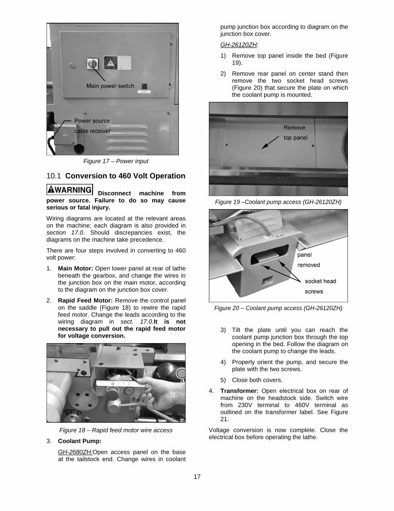
1. Main Motor: Open lower panel at rear of lathe beneath the gearbox, and change the wires in the junction box on the main motor, according to the diagram on the junction box cover.
2. Rapid Feed Motor: Remove the control panel on the saddle (Figure 18) to rewire the rapid feed motor. Change the leads according to the wiring diagram in sect. 17.0.It is not necessary to pull out the rapid feed motor for voltage conversion.
Figure 18 – Rapid feed motor wire access
3. Coolant Pump:
GH-2680ZH:Open access panel on the base at the tailstock end. Change wires in coolant
pump junction box according to diagram on the junction box cover.
GH-26120ZH:
1) Remove top panel inside the bed (Figure 19).
2) Remove rear panel on center stand then remove the two socket head screws (Figure 20) that secure the plate on which the coolant pump is mounted.
Figure 19 –Coolant pump access (GH-26120ZH)
Figure 20 – Coolant pump access (GH-26120ZH)
3) Tilt the plate until you can reach the coolant pump junction box through the top opening in the bed. Follow the diagram on the coolant pump to change the leads.
4) Properly orient the pump, and secure the plate with the two screws.
5) Close both covers.
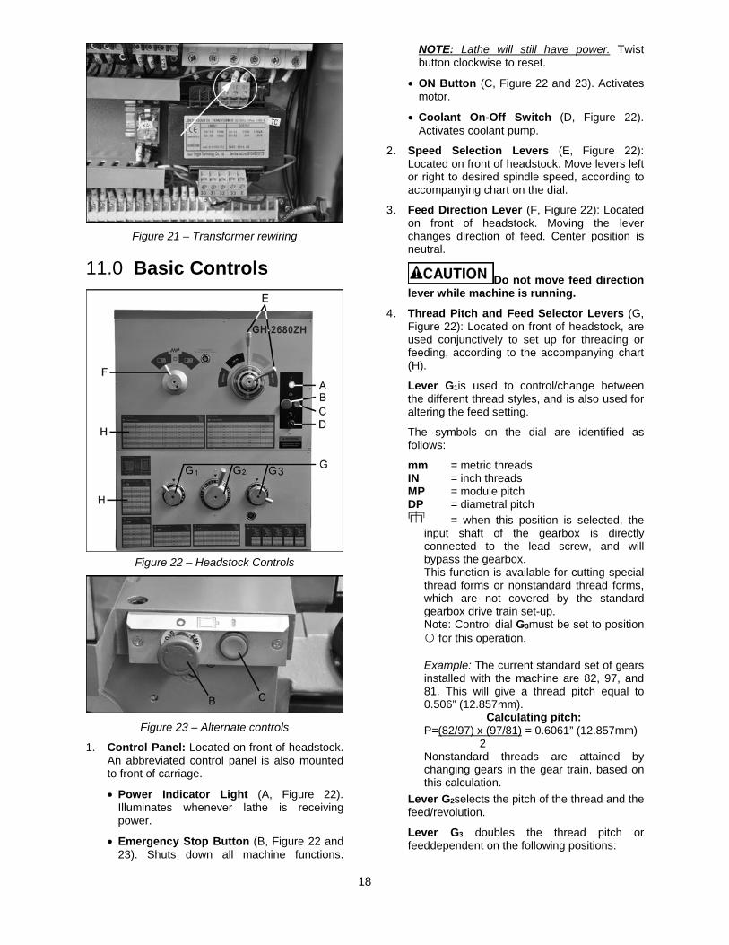
4. Transformer: Open electrical box on rear of machine on the headstock side. Switch wire from 230V terminal to 460V terminal as outlined on the transformer label. See Figure 21.
Voltage conversion is now complete. Close the electrical box before operating the lathe.
18
Figure 21 – Transformer rewiring
11.0 Basic Controls
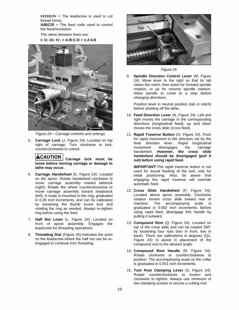
Figure 22 – Headstock Controls
Figure 23 – Alternate controls
1. Control Panel: Located on front of headstock. An abbreviated control panel is also mounted to front of carriage.
• Power Indicator Light (A, Figure 22). Illuminates whenever lathe is receiving power.
• Emergency Stop Button (B, Figure 22 and 23). Shuts down all machine functions.
NOTE: Lathe will still have power. Twist button clockwise to reset.
• ON Button (C, Figure 22 and 23). Activates motor.
• Coolant On-Off Switch (D, Figure 22). Activates coolant pump.
2. Speed Selection Levers (E, Figure 22): Located on front of headstock. Move levers left or right to desired spindle speed, according to accompanying chart on the dial.
3. Feed Direction Lever (F, Figure 22): Located on front of headstock. Moving the lever changes direction of feed. Center position is neutral.
Do not move feed direction lever while machine is running.
4. Thread Pitch and Feed Selector Levers (G, Figure 22): Located on front of headstock, are used conjunctively to set up for threading or feeding, according to the accompanying chart (H).
Lever G1is used to control/change between the different thread styles, and is also used for altering the feed setting.
The symbols on the dial are identified as follows:
mm = metric threads IN = inch threads MP = module pitch DP = diametral pitch
= when this position is selected, the input shaft of the gearbox is directly connected to the lead screw, and will bypass the gearbox. This function is available for cutting special thread forms or nonstandard thread forms, which are not covered by the standard gearbox drive train set-up. Note: Control dial G3must be set to position ○ for this operation. Example: The current standard set of gears installed with the machine are 82, 97, and 81. This will give a thread pitch equal to 0.506” (12.857mm).
Calculating pitch: P=(82/97) x (97/81) = 0.6061” (12.857mm) 2 Nonstandard threads are attained by changing gears in the gear train, based on this calculation.
Lever G2selects the pitch of the thread and the feed/revolution.
Lever G3 doubles the thread pitch or feeddependent on the following positions:
19
I/II/III/IV = The leadscrew is used to cut thread forms. A/B/C/D = The feed rodis used to control the feed/revolution. The ratios between them are: I: II: III: IV: = A:B:C:D = 1:2:4:8
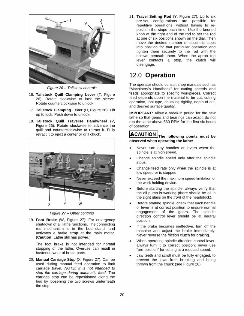
Figure 24 – Carriage controls and settings
5. Carriage Lock (J, Figure 24): Located on top right of carriage. Turn clockwise to lock, counterclockwise to unlock.
Carriage lock must be loose before moving carriage or damage to lathe may occur.
6. Carriage Handwheel (K, Figure 24): Located on the apron. Rotate handwheel clockwise to move carriage assembly toward tailstock (right). Rotate the wheel counterclockwise to move carriage assembly toward headstock (left). A scale is mounted to the ring, graduated in 0.05 inch increments, and can be calibrated by loosening the thumb screw lock and rotating the ring as needed. Always re-tighten ring before using the feed.
7. Half Nut Lever (L, Figure 24): Located on front of apron assembly. Engages the leadscrew for threading operations.
8. Threading Dial (Figure 25):Indicates the point on the leadscrew where the half nut can be re-engaged to continue inch threading.
Figure 25
9. Spindle Direction Control Lever (M, Figure 24). Move lever to the right so that its tab clears the notch, then down for forward spindle rotation, or up for reverse spindle rotation. Allow spindle to come to a stop before changing directions.
Position lever in neutral position (tab in notch) before shutting off the lathe.
10. Feed Direction Lever (N, Figure 24): Left and right moves the carriage in the corresponding directions (longitudinal feed); up and down moves the cross slide (cross feed).
11. Rapid Traverse Button (O, Figure 24). Push for rapid movement in the direction set by the feed direction lever. Rapid longitudinal movement disengages the carriage handwheel. However, the cross slide handwheel should be disengaged (pull it out) before using rapid feed.
IMPORTANT:The rapid traverse button is not used for actual feeding of the tool, only for initial positioning. Also, be aware that engaging the rapid traverse will override automatic feed.
12. Cross Slide Handwheel (P, Figure 24): Located above apron assembly. Clockwise rotation moves cross slide toward rear of machine. The accompanying scale is graduated in 0.002 inch increments. Before using rapid feed, disengage this handle by pulling it outward.
13. Compound Rest (Q, Figure 24): Located on top of the cross slide and can be rotated 360° by loosening four nuts (two in front, two in back). There are calibrations in degrees (Q1, Figure 24) to assist in placement of the compound rest to the desired angle.
14. Compound Rest Handle (R, Figure 24): Rotate clockwise or counterclockwise to position. The accompanying scale on the collar is graduated in 0.001 inch increments.
15. Tool Post Clamping Lever (S, Figure 24): Rotate counterclockwise to loosen and clockwise to tighten. Always use minimum of two clamping screws to secure a cutting tool.
20
Figure 26 – Tailstock controls
16. Tailstock Quill Clamping Lever (T, Figure 26): Rotate clockwise to lock the sleeve. Rotate counterclockwise to unlock.
17. Tailstock Clamping Lever (U, Figure 26): Lift up to lock. Push down to unlock.
18. Tailstock Quill Traverse Handwheel (V, Figure 26): Rotate clockwise to advance the quill and counterclockwise to retract it. Fully retract it to eject a center or drill chuck.
Figure 27 – Other controls
19. Foot Brake (W, Figure 27): For emergency shutdown of all lathe functions. The connecting rod mechanism is in the bed stand, and activates a brake strap at the main motor. (Caution: Lathe still has power.)
The foot brake is not intended for normal stopping of the lathe. Overuse can result in hastened wear of brake parts.
20. Manual Carriage Stop (X, Figure 27): Can be used during manual feed operation to limit carriage travel. NOTE: It is not intended to stop the carriage during automatic feed. The carriage stop can be repositioned along the bed by loosening the two screws underneath the stop.
21. Travel Setting Rod (Y, Figure 27): Up to six pre-set configurations are possible for repetitive operations, without having to re-position the stops each time. Use the knurled knob at the right end of the rod to set the rod at one of six positions shown on the dial. Then move the desired number of eccentric stops into position for that particular operation and tighten them securely to the rod with the screws beneath them. When the apron trip lever contacts a stop, the clutch will disengage.
12.0 Operation The operator should consult shop manuals such as “Machinery’s Handbook” for cutting speeds and feeds appropriate to specific workpieces. Correct feed depends upon the material to be cut, cutting operation, tool type, chucking rigidity, depth of cut, and desired surface quality.
IMPORTANT: Allow a break-in period for the new lathe so that gears and bearings can adapt; do not run the lathe above 560 RPM for the first six hours of operation.
The following points must be observed when operating the lathe:
• Never turn any handles or levers when the spindle is at high speed.
• Change spindle speed only after the spindle stops.
• Change feed rate only when the spindle is at low speed or is stopped.
• Never exceed the maximum speed limitation of the work holding device.
• Before starting the spindle, always verify that the oil pump is working (there should be oil in the sight glass on the front of the headstock).
• Before starting spindle, check that each handle or lever is at correct position to ensure normal engagement of the gears. The spindle direction control lever should be at neutral position.
• If the brake becomes ineffective, turn off the machine and adjust the brake immediately. Never reverse the friction clutch for braking.
• When operating spindle direction control lever, always turn it to correct position; never use “pre-position” for cutting at a reduced speed.
• Jaw teeth and scroll must be fully engaged, to prevent the jaws from breaking and being thrown from the chuck (see Figure 28).
21
Figure 28 – Insufficient jaw tooth engagement
• Avoid long workpiece extensions, as parts may bend or fly off (see figure 29). Use rests or the tailstock for support.
Figure 29 – Improper setups
• Avoid short clamping contact (Figure 30, A) or clamping on a minor part diameter (Figure 30, B). Face-locate the workpiece for added support.
Figure 30 – Improper setups
12.1 Tool Setup The cutting angle is correct when the cutting edge is in line with the center axis of the workpiece. Use
the point of the tailstock center as a gauge and shims under the tool to obtain the correct center height.
Use a minimum of two clamping screws to secure each tool.
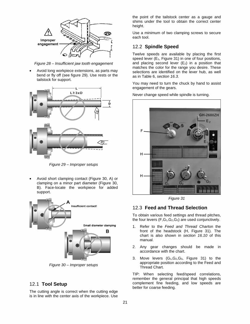
12.2 Spindle Speed Twelve speeds are available by placing the first speed lever (E1, Figure 31) in one of four positions, and placing second lever (E2) in a position that matches the color for the range you desire. These selections are identified on the lever hub, as well as in Table 6, section 16.3.
You may need to turn the chuck by hand to assist engagement of the gears.
Never change speed while spindle is turning.
Figure 31
12.3 Feed and Thread Selection To obtain various feed settings and thread pitches, the four levers (F,G1,G2,G3) are used conjunctively.
1. Refer to the Feed and Thread Charton the front of the headstock (H, Figure 31). The chart is also shown in section 16.10 of this manual.
2. Any gear changes should be made in accordance with the chart.
3. Move levers (G1,G2,G3, Figure 31) to the appropriate position according to the Feed and Thread Chart.
TIP: When selecting feed/speed correlations, remember the general principal that high speeds complement fine feeding, and low speeds are better for coarse feeding.
22
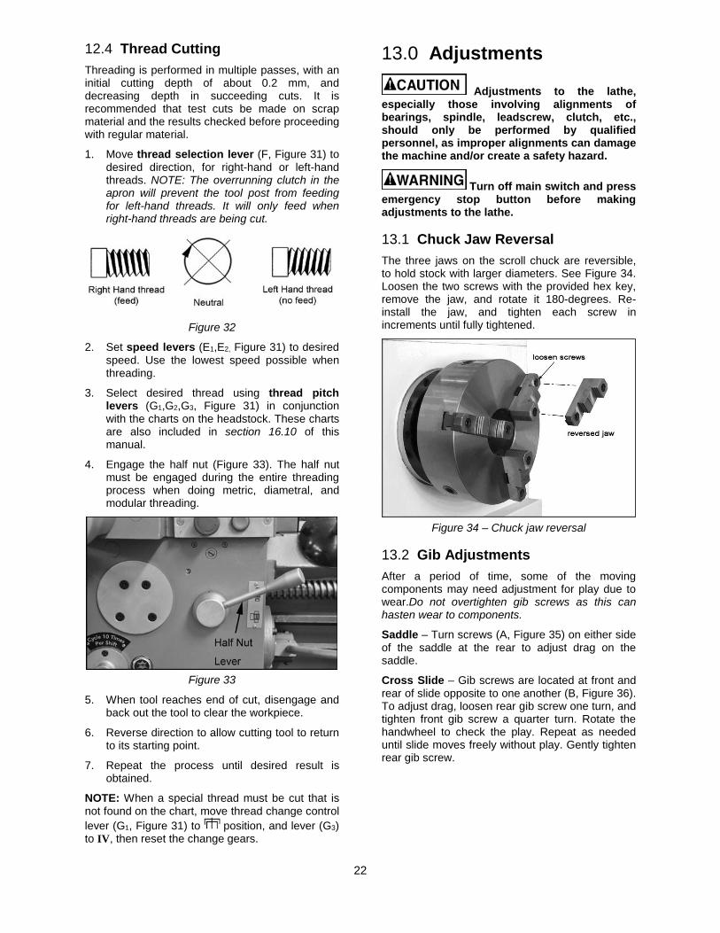
12.4 Thread Cutting Threading is performed in multiple passes, with an initial cutting depth of about 0.2 mm, and decreasing depth in succeeding cuts. It is recommended that test cuts be made on scrap material and the results checked before proceeding with regular material.
1. Move thread selection lever (F, Figure 31) to desired direction, for right-hand or left-hand threads. NOTE: The overrunning clutch in the apron will prevent the tool post from feeding for left-hand threads. It will only feed when right-hand threads are being cut.
Figure 32
2. Set speed levers (E1,E2, Figure 31) to desired speed. Use the lowest speed possible when threading.
3. Select desired thread using thread pitch levers (G1,G2,G3, Figure 31) in conjunction with the charts on the headstock. These charts are also included in section 16.10 of this manual.
4. Engage the half nut (Figure 33). The half nut must be engaged during the entire threading process when doing metric, diametral, and modular threading.
Figure 33
5. When tool reaches end of cut, disengage and back out the tool to clear the workpiece.
6. Reverse direction to allow cutting tool to return to its starting point.
7. Repeat the process until desired result is obtained.
NOTE: When a special thread must be cut that is not found on the chart, move thread change control lever (G1, Figure 31) to position, and lever (G3) to IV, then reset the change gears.
13.0 Adjustments
Adjustments to the lathe, especially those involving alignments of bearings, spindle, leadscrew, clutch, etc., should only be performed by qualified personnel, as improper alignments can damage the machine and/or create a safety hazard.
Turn off main switch and press emergency stop button before making adjustments to the lathe.
13.1 Chuck Jaw Reversal The three jaws on the scroll chuck are reversible, to hold stock with larger diameters. See Figure 34. Loosen the two screws with the provided hex key, remove the jaw, and rotate it 180-degrees. Re-install the jaw, and tighten each screw in increments until fully tightened.
Figure 34 – Chuck jaw reversal
13.2 Gib Adjustments After a period of time, some of the moving components may need adjustment for play due to wear.Do not overtighten gib screws as this can hasten wear to components.
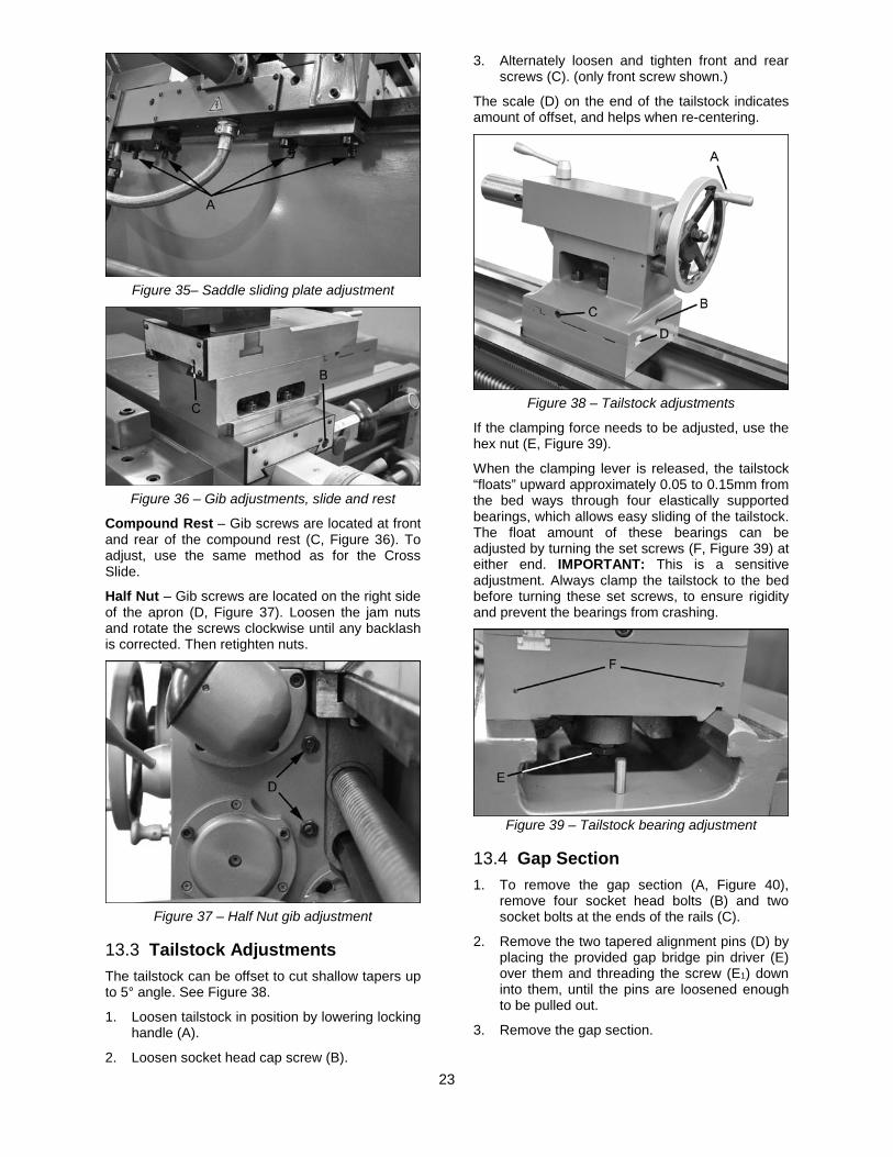
Saddle – Turn screws (A, Figure 35) on either side of the saddle at the rear to adjust drag on the saddle.
Cross Slide – Gib screws are located at front and rear of slide opposite to one another (B, Figure 36). To adjust drag, loosen rear gib screw one turn, and tighten front gib screw a quarter turn. Rotate the handwheel to check the play. Repeat as needed until slide moves freely without play. Gently tighten rear gib screw.
23
Figure 35– Saddle sliding plate adjustment
Figure 36 – Gib adjustments, slide and rest
Compound Rest – Gib screws are located at front and rear of the compound rest (C, Figure 36). To adjust, use the same method as for the Cross Slide.
Half Nut – Gib screws are located on the right side of the apron (D, Figure 37). Loosen the jam nuts and rotate the screws clockwise until any backlash is corrected. Then retighten nuts.
Figure 37 – Half Nut gib adjustment
13.3 Tailstock Adjustments The tailstock can be offset to cut shallow tapers up to 5° angle. See Figure 38.
1. Loosen tailstock in position by lowering locking handle (A).
2. Loosen socket head cap screw (B).
3. Alternately loosen and tighten front and rear screws (C). (only front screw shown.)
The scale (D) on the end of the tailstock indicates amount of offset, and helps when re-centering.
Figure 38 – Tailstock adjustments
If the clamping force needs to be adjusted, use the hex nut (E, Figure 39).
When the clamping lever is released, the tailstock “floats” upward approximately 0.05 to 0.15mm from the bed ways through four elastically supported bearings, which allows easy sliding of the tailstock. The float amount of these bearings can be adjusted by turning the set screws (F, Figure 39) at either end. IMPORTANT: This is a sensitive adjustment. Always clamp the tailstock to the bed before turning these set screws, to ensure rigidity and prevent the bearings from crashing.
Figure 39 – Tailstock bearing adjustment
13.4 Gap Section 1. To remove the gap section (A, Figure 40),
remove four socket head bolts (B) and two socket bolts at the ends of the rails (C).
2. Remove the two tapered alignment pins (D) by placing the provided gap bridge pin driver (E) over them and threading the screw (E1) down into them, until the pins are loosened enough to be pulled out.
3. Remove the gap section.
24
Figure 40 – Gap section
To reinstall the gap section:
4. Clean the bottom and the ends of the gap section thoroughly.
5. Set gap section in place and align the ends.
6. Insert the tapered pins into their holes through the gap and into the lathe bed.
7. Reinstall the six bolts (B/C), and tighten alternately until all are snug. Make sure gap remains aligned with the ways while tightening the screws.
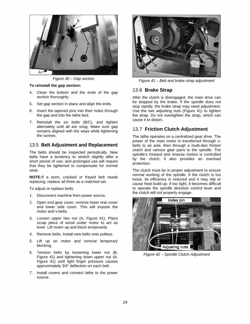
13.5 Belt Adjustment and Replacement The belts should be inspected periodically. New belts have a tendency to stretch slightly after a short period of use; and prolonged use will require that they be tightened to compensate for normal wear.
NOTE:If a worn, cracked or frayed belt needs replacing, replace all three as a matched set.
To adjust or replace belts:
1. Disconnect machine from power source.
2. Open end gear cover, remove lower rear cover and lower side cover. This will expose the motor and v-belts.
3. Loosen upper hex nut (A, Figure 41). Place scrap piece of wood under motor to act as lever. Lift motor up and block temporarily.
4. Remove belts. Install new belts onto pulleys.
5. Lift up on motor and remove temporary blocking.
6. Tension belts by loosening lower nut (B, Figure 41) and tightening down upper nut (A, Figure 41) until light finger pressure causes approximately 3/4” deflection on each belt.
7. Install covers and connect lathe to the power source.
Figure 41 – Belt and brake strap adjustment
13.6 Brake Strap After the clutch is disengaged, the main drive can be stopped by the brake. If the spindle does not stop rapidly, the brake strap may need adjustment. Use the two adjusting nuts (Figure 41) to tighten the strap. Do not overtighten the strap, which can cause it to distort.
13.7 Friction Clutch Adjustment The lathe operates on a centralized gear drive. The power of the main motor is transferred through v-belts to an axle, then through a multi-disc friction clutch and various gear pairs to the spindle. The spindle’s forward and reverse motion is controlled by the clutch; it also provides an overload protection.
The clutch must be in proper adjustment to ensure normal working of the spindle. If the clutch is too loose, its efficiency is reduced and it may slip or cause heat build-up; if too tight, it becomes difficult to operate the spindle direction control lever and the clutch will not properly engage.
Figure 42 – Spindle Clutch Adjustment
25
Figure 43 – Spindle Clutch Adjustment
1. Make sure the lathe is OFF at the master switch.
2. Remove the top cover of the headstock.
3. Determine the appropriate clutch.
4. Use a screwdriver to push in the index pin (Figures 42 and 43). The pin is spring loaded.
5. Rotate the adjusting nut to the next index position, which will be indicated by a “click.”
NOTE: The clutch reacts quickly; adjust clutch nut by one division only. You must feel and hear the clutch engagement – a clicking sound. If clutch adjustment is too tight, it will not engage.
If the spindle does not stop in the OFF position, the forward/reverse clutch adjustment is out of balance. (The spindle follows the direction with the tighter clutch adjustment).
6. Reinstall headstock cover, and test the clutch function.
NOTE: Never reverse the friction clutch for braking.
13.8 Aligning Tailstock to Headstock Headstock and Tailstock have been aligned at the factory and should not require attention. If future adjustment should ever be needed, proceed as follows. (Make sure that twist in the lathe bed is not contributing to the problem – refer tosection 8.1,Leveling the Lathe.)
1. Fit a 12” ground, center-drilled, steel bar between centers of the headstock and tailstock (Figure 44).
2. Fit a dial indicator to the top slide and traverse the center line of the bar. If it indicates a taper, adjustment is needed.
3. Align the tailstock using the off-set screws at front and back (see C, Figure 38) until the tailstock is aligned.
Figure 44 – Tailstock/Headstock alignment
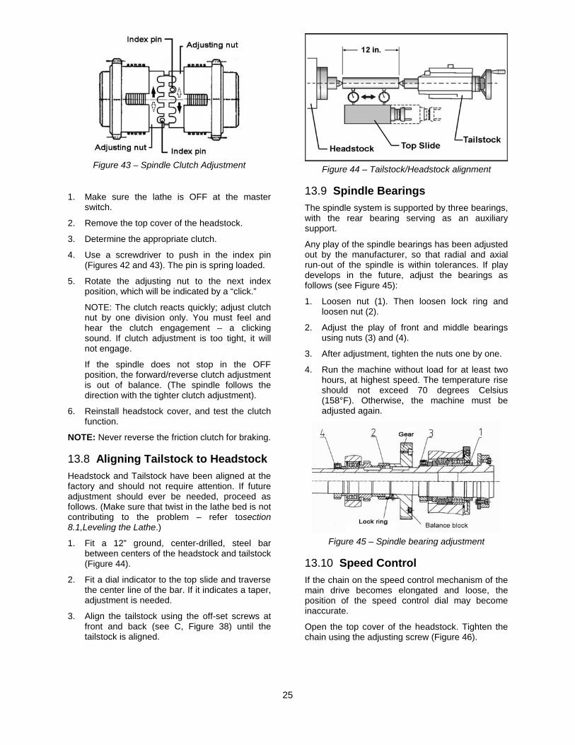
13.9 Spindle Bearings The spindle system is supported by three bearings, with the rear bearing serving as an auxiliary support.
Any play of the spindle bearings has been adjusted out by the manufacturer, so that radial and axial run-out of the spindle is within tolerances. If play develops in the future, adjust the bearings as follows (see Figure 45):
1. Loosen nut (1). Then loosen lock ring and loosen nut (2).
2. Adjust the play of front and middle bearings using nuts (3) and (4).
3. After adjustment, tighten the nuts one by one.
4. Run the machine without load for at least two hours, at highest speed. The temperature rise should not exceed 70 degrees Celsius (158°F). Otherwise, the machine must be adjusted again.
Figure 45 – Spindle bearing adjustment
13.10 Speed Control If the chain on the speed control mechanism of the main drive becomes elongated and loose, the position of the speed control dial may become inaccurate.
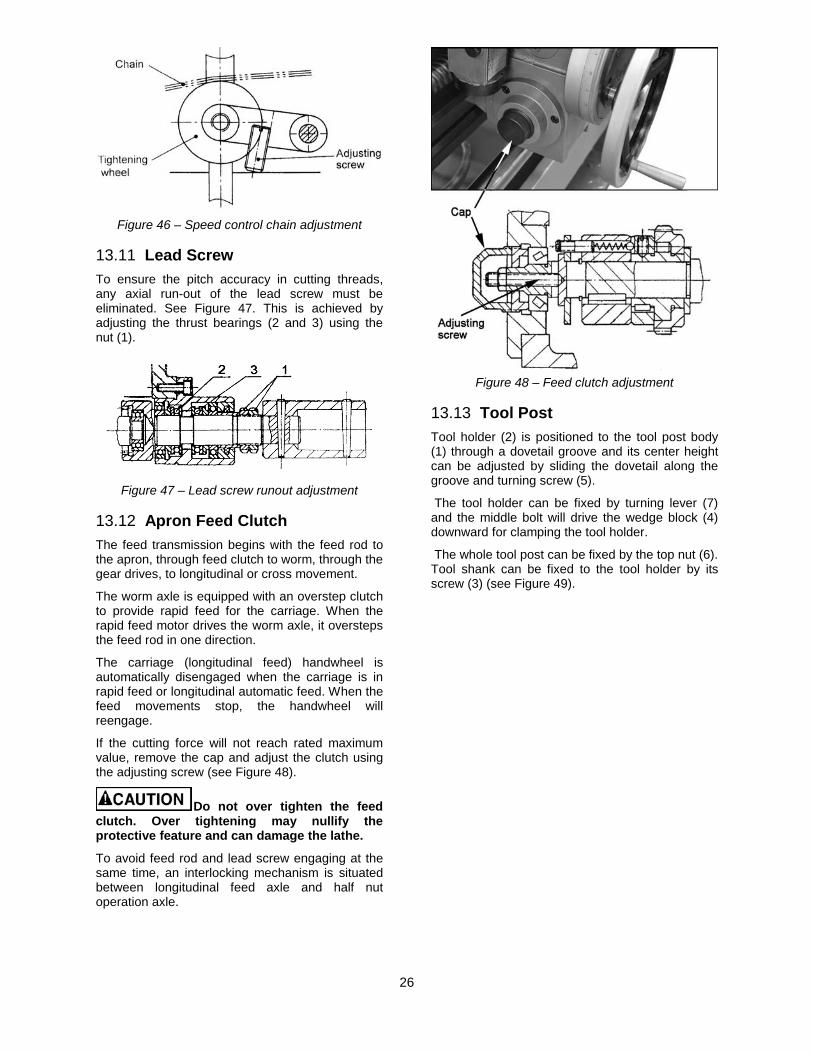
Open the top cover of the headstock. Tighten the chain using the adjusting screw (Figure 46).
26
Figure 46 – Speed control chain adjustment
13.11 Lead Screw To ensure the pitch accuracy in cutting threads, any axial run-out of the lead screw must be eliminated. See Figure 47. This is achieved by adjusting the thrust bearings (2 and 3) using the nut (1).
Figure 47 – Lead screw runout adjustment
13.12 Apron Feed Clutch The feed transmission begins with the feed rod to the apron, through feed clutch to worm, through the gear drives, to longitudinal or cross movement.
The worm axle is equipped with an overstep clutch to provide rapid feed for the carriage. When the rapid feed motor drives the worm axle, it oversteps the feed rod in one direction.
The carriage (longitudinal feed) handwheel is automatically disengaged when the carriage is in rapid feed or longitudinal automatic feed. When the feed movements stop, the handwheel will reengage.
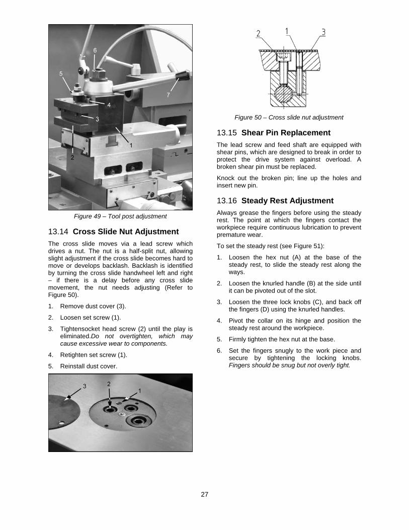
If the cutting force will not reach rated maximum value, remove the cap and adjust the clutch using the adjusting screw (see Figure 48).
Do not over tighten the feed clutch. Over tightening may nullify the protective feature and can damage the lathe.
To avoid feed rod and lead screw engaging at the same time, an interlocking mechanism is situated between longitudinal feed axle and half nut operation axle.
Figure 48 – Feed clutch adjustment
13.13 Tool Post Tool holder (2) is positioned to the tool post body (1) through a dovetail groove and its center height can be adjusted by sliding the dovetail along the groove and turning screw (5).
The tool holder can be fixed by turning lever (7) and the middle bolt will drive the wedge block (4) downward for clamping the tool holder.
The whole tool post can be fixed by the top nut (6). Tool shank can be fixed to the tool holder by its screw (3) (see Figure 49).
27
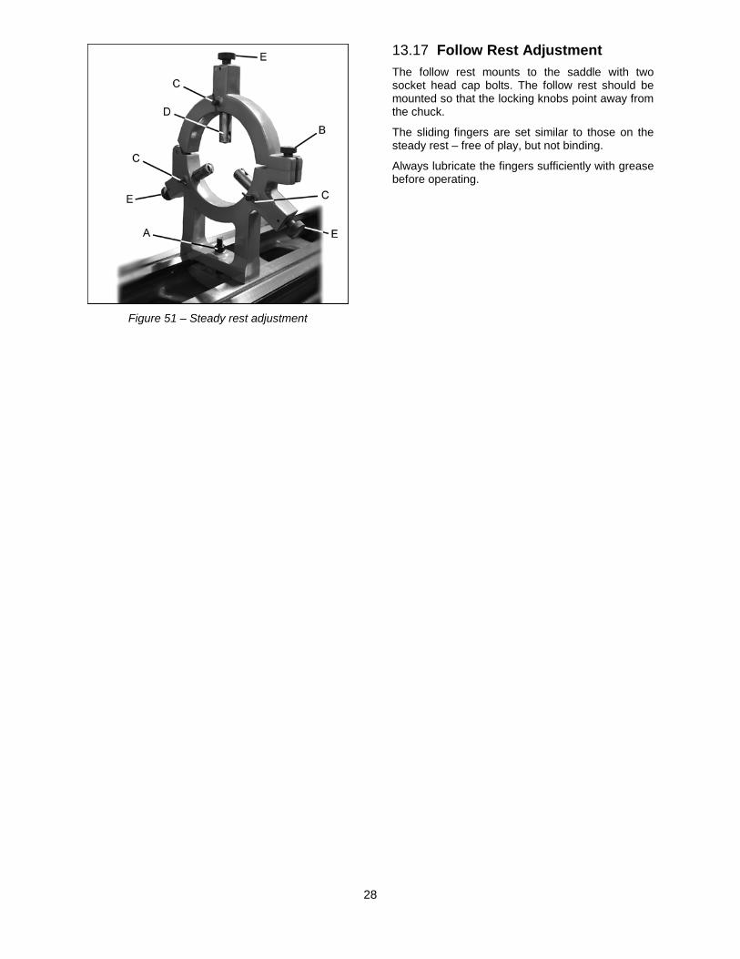
Figure 49 – Tool post adjustment
13.14 Cross Slide Nut Adjustment The cross slide moves via a lead screw which drives a nut. The nut is a half-split nut, allowing slight adjustment if the cross slide becomes hard to move or develops backlash. Backlash is identified by turning the cross slide handwheel left and right – if there is a delay before any cross slide movement, the nut needs adjusting (Refer to Figure 50).
1. Remove dust cover (3).
2. Loosen set screw (1).
3. Tightensocket head screw (2) until the play is eliminated.Do not overtighten, which may cause excessive wear to components.
4. Retighten set screw (1).
5. Reinstall dust cover.
Figure 50 – Cross slide nut adjustment
13.15 Shear Pin Replacement The lead screw and feed shaft are equipped with shear pins, which are designed to break in order to protect the drive system against overload. A broken shear pin must be replaced.
Knock out the broken pin; line up the holes and insert new pin.
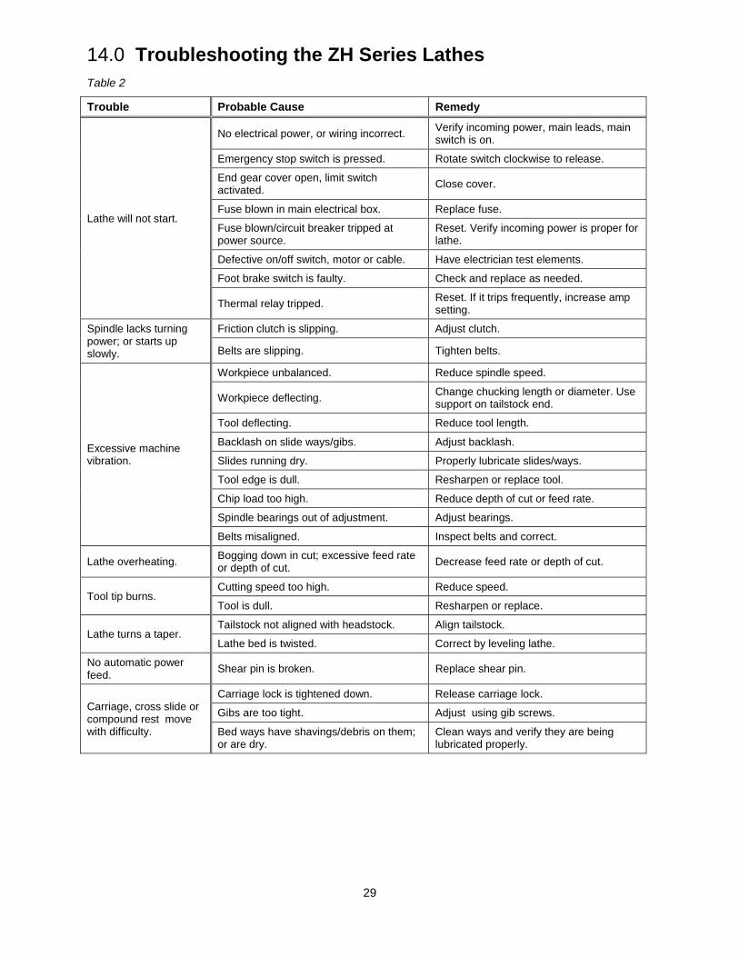
13.16 Steady Rest Adjustment Always grease the fingers before using the steady rest. The point at which the fingers contact the workpiece require continuous lubrication to prevent premature wear.
To set the steady rest (see Figure 51):
1. Loosen the hex nut (A) at the base of the steady rest, to slide the steady rest along the ways.
2. Loosen the knurled handle (B) at the side until it can be pivoted out of the slot.
3. Loosen the three lock knobs (C), and back off the fingers (D) using the knurled handles.
4. Pivot the collar on its hinge and position the steady rest around the workpiece.
5. Firmly tighten the hex nut at the base.
6. Set the fingers snugly to the work piece and secure by tightening the locking knobs. Fingers should be snug but not overly tight.
28
Figure 51 – Steady rest adjustment
13.17 Follow Rest Adjustment The follow rest mounts to the saddle with two socket head cap bolts. The follow rest should be mounted so that the locking knobs point away from the chuck.
The sliding fingers are set similar to those on the steady rest – free of play, but not binding.
Always lubricate the fingers sufficiently with grease before operating.
29
14.0 Troubleshooting the ZH Series Lathes Table 2
Trouble Probable Cause Remedy
Lathe will not start.
No electrical power, or wiring incorrect. Verify incoming power, main leads, main switch is on.
Emergency stop switch is pressed. Rotate switch clockwise to release.
End gear cover open, limit switch activated. Close cover.
Fuse blown in main electrical box. Replace fuse.
Fuse blown/circuit breaker tripped at power source.
Reset. Verify incoming power is proper for lathe.
Defective on/off switch, motor or cable. Have electrician test elements.
Foot brake switch is faulty. Check and replace as needed.
Thermal relay tripped. Reset. If it trips frequently, increase amp setting.
Spindle lacks turning power; or starts up slowly.
Friction clutch is slipping. Adjust clutch.
Belts are slipping. Tighten belts.
Excessive machine vibration.
Workpiece unbalanced. Reduce spindle speed.
Workpiece deflecting. Change chucking length or diameter. Use support on tailstock end.
Tool deflecting. Reduce tool length.
Backlash on slide ways/gibs. Adjust backlash.
Slides running dry. Properly lubricate slides/ways.
Tool edge is dull. Resharpen or replace tool.
Chip load too high. Reduce depth of cut or feed rate.
Spindle bearings out of adjustment. Adjust bearings.
Belts misaligned. Inspect belts and correct.
Lathe overheating. Bogging down in cut; excessive feed rate or depth of cut. Decrease feed rate or depth of cut.
Tool tip burns. Cutting speed too high. Reduce speed.
Tool is dull. Resharpen or replace.
Lathe turns a taper. Tailstock not aligned with headstock. Align tailstock.
Lathe bed is twisted. Correct by leveling lathe.
No automatic power feed. Shear pin is broken. Replace shear pin.
Carriage, cross slide or compound rest move with difficulty.
Carriage lock is tightened down. Release carriage lock.
Gibs are too tight. Adjust using gib screws.
Bed ways have shavings/debris on them; or are dry.
Clean ways and verify they are being lubricated properly.
30
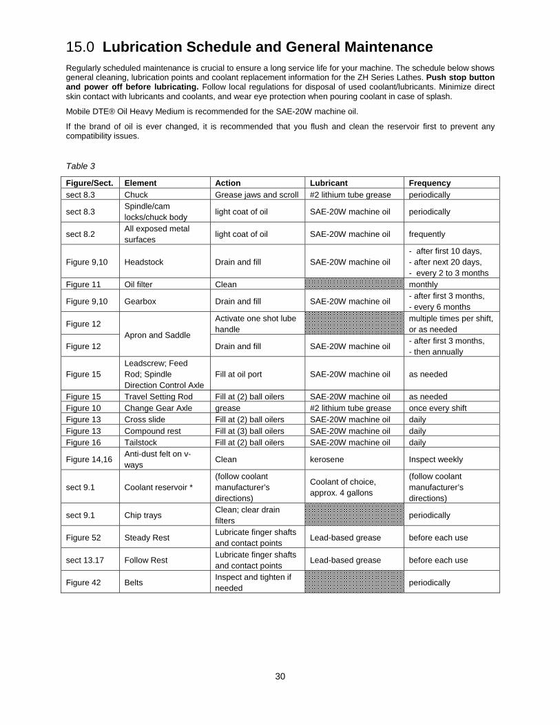
15.0 Lubrication Schedule and General Maintenance Regularly scheduled maintenance is crucial to ensure a long service life for your machine. The schedule below shows general cleaning, lubrication points and coolant replacement information for the ZH Series Lathes. Push stop button and power off before lubricating. Follow local regulations for disposal of used coolant/lubricants. Minimize direct skin contact with lubricants and coolants, and wear eye protection when pouring coolant in case of splash.
Mobile DTE® Oil Heavy Medium is recommended for the SAE-20W machine oil.
If the brand of oil is ever changed, it is recommended that you flush and clean the reservoir first to prevent any compatibility issues.
Table 3
Figure/Sect. Element Action Lubricant Frequency sect 8.3 Chuck Grease jaws and scroll #2 lithium tube grease periodically
sect 8.3 Spindle/cam locks/chuck body
light coat of oil SAE-20W machine oil periodically
sect 8.2 All exposed metal surfaces
light coat of oil SAE-20W machine oil frequently
Figure 9,10 Headstock Drain and fill SAE-20W machine oil - after first 10 days, - after next 20 days, - every 2 to 3 months
Figure 11 Oil filter Clean monthly
Figure 9,10 Gearbox Drain and fill SAE-20W machine oil - after first 3 months, - every 6 months
Figure 12 Apron and Saddle
Activate one shot lube handle
multiple times per shift, or as needed
Figure 12 Drain and fill SAE-20W machine oil - after first 3 months, - then annually
Figure 15 Leadscrew; Feed Rod; Spindle Direction Control Axle
Fill at oil port SAE-20W machine oil as needed
Figure 15 Travel Setting Rod Fill at (2) ball oilers SAE-20W machine oil as needed Figure 10 Change Gear Axle grease #2 lithium tube grease once every shift Figure 13 Cross slide Fill at (2) ball oilers SAE-20W machine oil daily Figure 13 Compound rest Fill at (3) ball oilers SAE-20W machine oil daily Figure 16 Tailstock Fill at (2) ball oilers SAE-20W machine oil daily
Figure 14,16 Anti-dust felt on v-ways
Clean kerosene Inspect weekly
sect 9.1 Coolant reservoir * (follow coolant manufacturer’s directions)
Coolant of choice, approx. 4 gallons
(follow coolant manufacturer’s directions)
sect 9.1 Chip trays Clean; clear drain filters
periodically
Figure 52 Steady Rest Lubricate finger shafts and contact points
Lead-based grease before each use
sect 13.17 Follow Rest Lubricate finger shafts and contact points
Lead-based grease before each use
Figure 42 Belts Inspect and tighten if needed
periodically
31
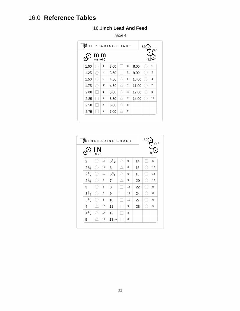
16.0 Reference Tables 16.1Inch Lead And Feed
Table 4
81
9782
m mT H R E A D I N G C H A R T
1.00
1.25
1.50
1.75
2.00
2.25
2.50
2.75
3.00
3.50
4.00
4.50
5.00
5.50
6.00
7.00
8.00
9.00
10.00
11.00
12.00
14.00
1
4
8
11
1
2
4
7
8
11
8
11
1
2
4
7
8
11
1
2
4
7
81
9782T H R E A D I N G C H A R T
I NI N C H
212 4
212
32 4
333 8
312
4
412
5
512
636 4
7
8
9
10
11
12
1312
14
16
18
20
22
24
27
28
15
14
12
9
8
6
5
15
14
12
9
8
6
5
15
14
12
9
8
6
5
15
14
12
9
8
6
5
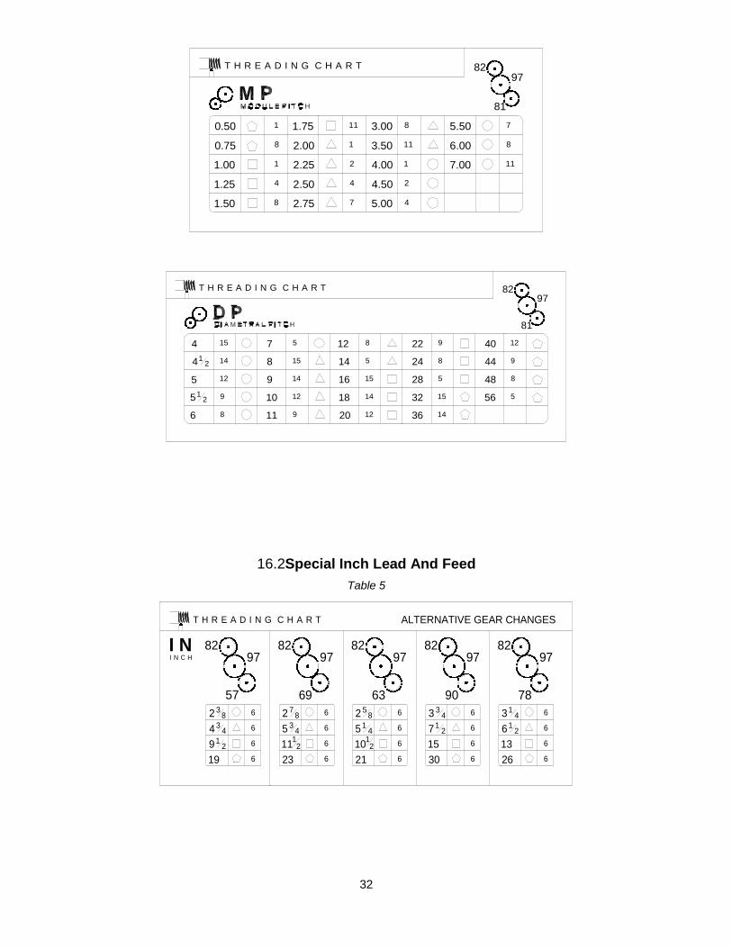
32
16.2Special Inch Lead And Feed Table 5
57
9782
69
9782
63
9782
90
9782
78
9782
T H R E A D I N G C H A R T
I NI N C H
ALTERNATIVE GEAR CHANGES
2 38
434
912
19
2 78
5 34
1112
23
2 58
514
1012
21
3 34
712
1530
314
612
1326
6
6
6
6
6
6
6
6
6
6
6
6
6
6
6
6
6
6
6
6
81
9782T H R E A D I N G C H A R T
0.50
0.75
1.00
1.25
1.50
1.75
2.00
2.25
2.50
2.75
3.00
3.50
4.00
4.50
5.00
5.50
6.00
7.00
8
11
78
11
1
2
4
1
4
8
1
8
11
1
2
4
7
81
9782T H R E A D I N G C H A R T
4
412
5
512
6
7
8
9
10
11
14
16
18
20
12 22
24
28
32
36
40
44
48
56
15
14
12
9
8
15
14
12
9
5 8
5
15
14
12
9
8
5
15
14
9
8
5
12
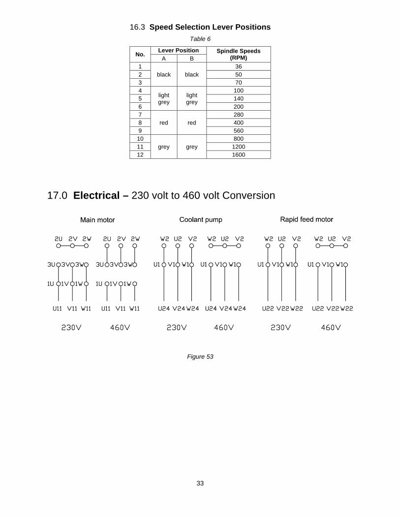
33
16.3 Speed Selection Lever Positions Table 6
No. Lever Position Spindle Speeds (RPM) A B
1 black black
36 2 50 3 70 4
light grey
light grey
100 5 140 6 200 7
red red 280
8 400 9 560 10
grey grey 800
11 1200 12 1600
17.0 Electrical – 230 volt to 460 volt Conversion
Figure 53
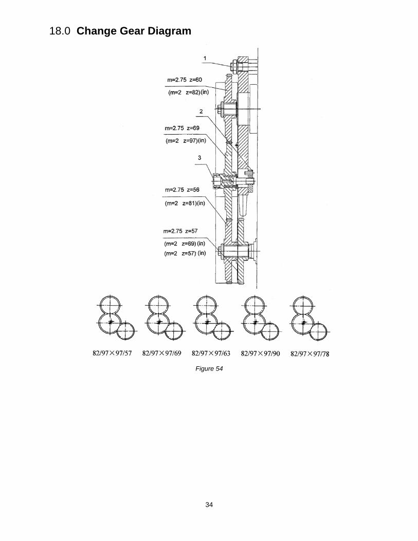
34
18.0 Change Gear Diagram
Figure 54

35
This page intentionally left blank.

36
This page intentionally left blank.
427 New Sanford Road LaVergne, Tennessee 37086
Phone: 800-274-6848 www.jettools.com
Parts List and Electrical Diagrams ZH Series Lathes Models GH-2680ZH; GH-26120ZH
Model GH-2680ZH shown
For ZH-Series Lathes Operation and Maintenance Instructions, see document M-321860
JET
427 New Sanford Road LaVergne, Tennessee 37086 Part No. M-321860-1 Ph.: 800-274-6848 Revision E 10/2017 www.jettools.com Copyright © 2017 JET
2
Warranty and Service JET warrants every product it sells against manufacturers’ defects. If one of our tools needs service or repair, please contact Technical Service by calling 1-800-274-6846, 8AM to 5PM CST, Monday through Friday.
Warranty Period The general warranty lasts for the time period specified in the literature included with your product or on the official JET branded website.
• JET products carry a limited warranty which varies in duration based upon the product. (See chart below) • Accessories carry a limited warranty of one year from the date of receipt. • Consumable items are defined as expendable parts or accessories expected to become inoperable within a
reasonable amount of use and are covered by a 90 day limited warranty against manufacturer’s defects.
Who is Covered This warranty covers only the initial purchaser of the product from the date of delivery.
What is Covered This warranty covers any defects in workmanship or materials subject to the limitations stated below. This warranty does not cover failures due directly or indirectly to misuse, abuse, negligence or accidents, normal wear-and-tear, improper repair, alterations or lack of maintenance. JET woodworking machinery is designed to be used with Wood. Use of these machines in the processing of metal, plastics, or other materials may void the warranty. The exceptions are acrylics and other natural items that are made specifically for wood turning.
Warranty Limitations Woodworking products with a Five Year Warranty that are used for commercial or industrial purposes default to a Two Year Warranty. Please contact Technical Service at 1-800-274-6846 for further clarification.
How to Get Technical Support Please contact Technical Service by calling 1-800-274-6846.Please note that you will be asked to provide proof of initial purchase when calling. If a product requires further inspection, the Technical Service representative will explain and assist with any additional action needed. JET has Authorized Service Centers located throughout the United States. For the name of an Authorized Service Center in your area call 1-800-274-6846 or use the Service Center Locator on the JET website.
More Information JET is constantly adding new products. For complete, up-to-date product information, check with your local distributor or visit the JET website.
How State Law Applies This warranty gives you specific legal rights, subject to applicable state law.
Limitations on This Warranty JET LIMITS ALL IMPLIED WARRANTIES TO THE PERIOD OF THE LIMITED WARRANTY FOR EACH PRODUCT. EXCEPT AS STATED HEREIN, ANY IMPLIED WARRANTIES OF MERCHANTABILITY AND FITNESS FOR A PARTICULAR PURPOSE ARE EXCLUDED. SOME STATES DO NOT ALLOW LIMITATIONS ON HOW LONG AN IMPLIED WARRANTY LASTS, SO THE ABOVE LIMITATION MAY NOT APPLY TO YOU. JET SHALL IN NO EVENT BE LIABLE FOR DEATH, INJURIES TO PERSONS OR PROPERTY, OR FOR INCIDENTAL, CONTINGENT, SPECIAL, OR CONSEQUENTIAL DAMAGES ARISING FROM THE USE OF OUR PRODUCTS. SOME STATES DO NOT ALLOW THE EXCLUSION OR LIMITATION OF INCIDENTAL OR CONSEQUENTIAL DAMAGES, SO THE ABOVE LIMITATION OR EXCLUSION MAY NOT APPLY TO YOU. JET sells through distributors only. The specifications listed in JET printed materials and on official JET website are given as general information and are not binding. JET reserves the right to effect at any time, without prior notice, those alterations to parts, fittings, and accessory equipment which they may deem necessary for any reason whatsoever. JET® branded products are not sold in Canada by JPW Industries, Inc.
Product Listing with Warranty Period 90 Days – Parts; Consumable items 1 Year – Motors; Machine Accessories 2 Year – Metalworking Machinery; Electric Hoists, Electric Hoist Accessories; Woodworking Machinery used for industrial or commercial purposes 5 Year – Woodworking Machinery Limited Lifetime – JET Parallel clamps; VOLT Series Electric Hoists; Manual Hoists; Manual Hoist Accessories; Shop Tools; Warehouse & Dock products; Hand Tools; Air Tools NOTE: JET is a division of JPW Industries, Inc. References in this document to JET also apply to JPW Industries, Inc., or any of its successors in interest to the JET brand.
3
Table of Contents 1.1 Bed Assembly I – Exploded View....................................................................................................... 4 1.2 Bed Assembly I (for 120” ZH only) – Exploded View ......................................................................... 5 1.3 Bed Assembly I – Parts List ............................................................................................................... 6 2.1 Bed Assembly II – Exploded View...................................................................................................... 8 2.2 Bed Assembly II (for 120” ZH only) – Exploded View ........................................................................ 9 2.3 Bed Assembly II – Parts List ............................................................................................................ 10 3.1 Headstock Assembly I – Exploded View .......................................................................................... 12 3.2 Headstock Assembly I – Parts List ................................................................................................... 13 4.1 Headstock Assembly II – Exploded View ......................................................................................... 15 4.2 Headstock Assembly II – Parts List .................................................................................................. 16 5.1 Headstock Assembly III – Exploded View ........................................................................................ 18 5.2 Headstock Assembly III – Parts List ................................................................................................. 19 6.1 Headstock Assembly IV – Exploded View ....................................................................................... 20 6.2 Headstock Assembly IV – Parts List ................................................................................................ 21 7.1 Headstock Assembly V – Exploded View ........................................................................................ 23 7.2 Headstock Assembly V – Parts List ................................................................................................. 24 8.1 Gear Assembly – Exploded View ..................................................................................................... 25 8.2 Gear Assembly – Parts List .............................................................................................................. 25 9.1 Gear Box Assembly I – Exploded View ............................................................................................ 26 9.2 Gear Box Assembly I – Parts List..................................................................................................... 27 10.1 Gear Box Assembly II – Exploded View ......................................................................................... 28 10.2 Gear Box Assembly II – Parts List.................................................................................................. 29 11.1 Gear Box Assembly III – Exploded View ........................................................................................ 31 11.2 Gear Box Assembly III – Parts List................................................................................................. 32 12.1 Brake Assembly – Exploded View ................................................................................................. 34 12.2 Brake Assembly – Parts List .......................................................................................................... 35 13.1 Saddle and Cross Slide Assembly – Exploded View ..................................................................... 36 13.2 Saddle and Cross Slide Assembly – Parts List .............................................................................. 37 14.1 Tool Post and Compound Rest Assembly – Exploded View ......................................................... 39 14.2 Tool Post and Compound Rest Assembly – Parts List .................................................................. 40 15.1 Apron Assembly I – Exploded View ............................................................................................... 41 15.2 Apron Assembly I – Parts List ........................................................................................................ 42 16.1 Apron Assembly II – Exploded View .............................................................................................. 44 16.2 Apron Assembly II – Parts List ....................................................................................................... 45 17.1 Apron Assembly III – Exploded View ............................................................................................. 47 17.2 Apron Assembly III – Parts List ...................................................................................................... 48 18.1 Apron Assembly IV – Exploded View ............................................................................................. 49 18.2 Apron Assembly IV – Parts List ...................................................................................................... 50 19.1 Tailstock Assembly I – Exploded View ........................................................................................... 51 19.2 Tailstock Assembly I – Parts List.................................................................................................... 52 20.1 Tailstock Assembly II – Exploded View .......................................................................................... 53 20.2 Tailstock Assembly II – Parts List................................................................................................... 54 21.1 Steady Rest Assembly (Small and Large) – Exploded View ......................................................... 55 21.2 Steady Rest Assembly (Small) – Parts List .................................................................................... 56 21.3 Steady Rest Assembly (Large) – Parts List ................................................................................... 56 22.1 Follow Rest Assembly – Exploded View ........................................................................................ 57 22.2 Follow Rest Assembly – Parts List ................................................................................................. 57 23.1 Coolant and Work Light Assembly – Exploded View ..................................................................... 58 23.2 Coolant and Work Light Assembly – Parts List .............................................................................. 58 24.1 Travel Stop Assembly – Exploded View ........................................................................................ 59 24.2 Travel Stop Assembly – Parts List ................................................................................................. 60 25.1 Small Carriage Stop – Exploded View ........................................................................................... 61 25.2 Small Carriage Stop – Parts List .................................................................................................... 61 26.1 Toolbox, Accessories, and Attachments ........................................................................................ 62 27.1 Electrical Components ................................................................................................................... 63 27.2 Electrical Diagram .......................................................................................................................... 64 27.3 Electrical Components – Parts List ................................................................................................ 65 28.1 Chuck Guard Assembl – Exploded View y ..................................................................................... 66 28.2 Chuck Guard Assembly – Parts List .............................................................................................. 66 29.1 Carriage Lubrication – Exploded View ........................................................................................... 67 29.2 Carriage Lubrication– Parts List ..................................................................................................... 67
Ordering Replacement Parts....................................................................................................................... 68
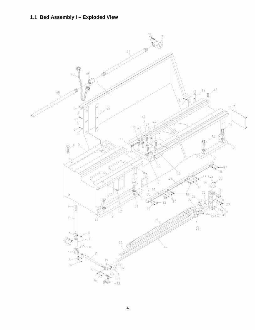
4
1.1 Bed Assembly I – Exploded View
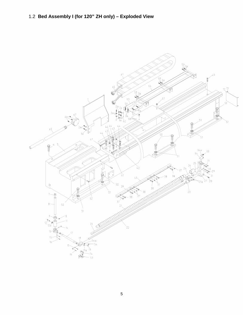
5
1.2 Bed Assembly I (for 120” ZH only) – Exploded View
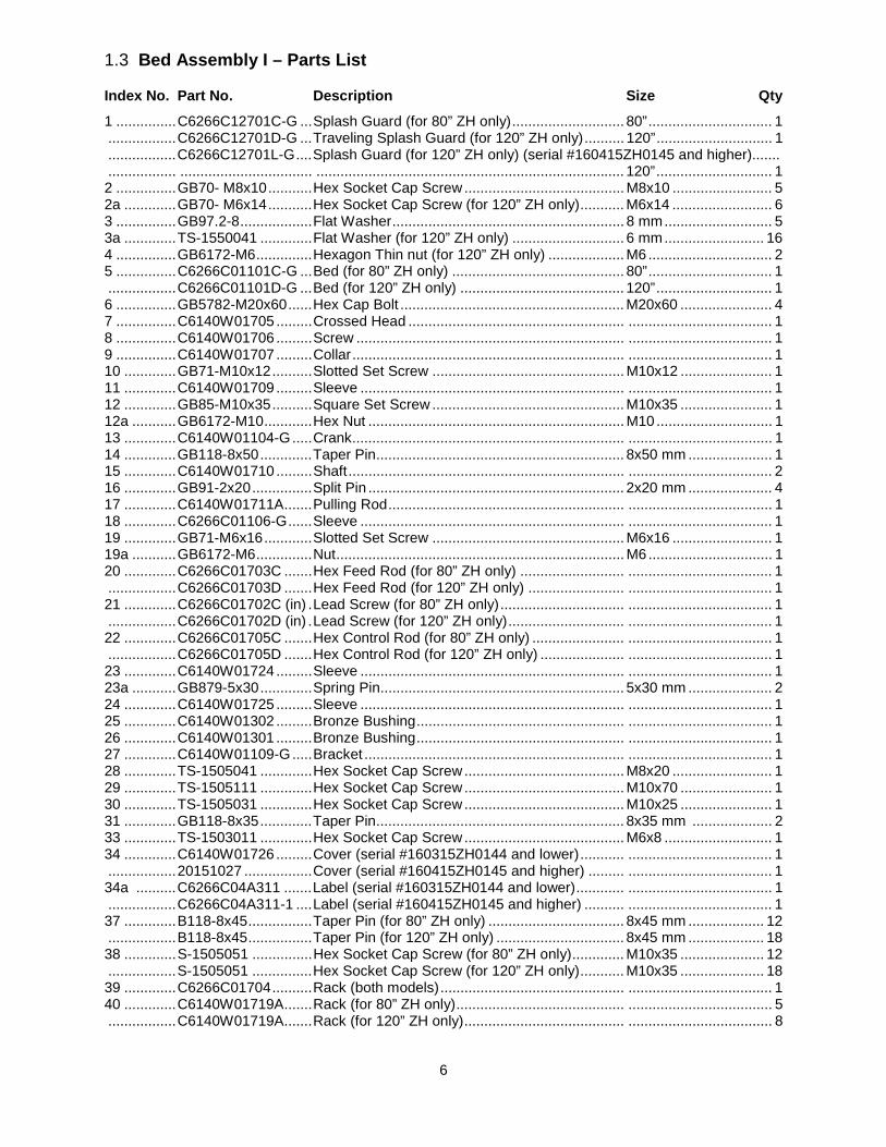
6
1.3 Bed Assembly I – Parts List
Index No. Part No. Description Size Qty
1 ............... C6266C12701C-G ... Splash Guard (for 80” ZH only) ............................ 80” ............................... 1 ................. C6266C12701D-G ... Traveling Splash Guard (for 120” ZH only) .......... 120” ............................. 1 ................. C6266C12701L-G .... Splash Guard (for 120” ZH only) (serial #160415ZH0145 and higher)....... ................. ................................. ............................................................................. 120” ............................. 1 2 ............... GB70- M8x10 ........... Hex Socket Cap Screw ........................................ M8x10 ......................... 5 2a ............. GB70- M6x14 ........... Hex Socket Cap Screw (for 120” ZH only) ........... M6x14 ......................... 6 3 ............... GB97.2-8 .................. Flat Washer .......................................................... 8 mm ........................... 5 3a ............. TS-1550041 ............. Flat Washer (for 120” ZH only) ............................ 6 mm ......................... 16 4 ............... GB6172-M6 .............. Hexagon Thin nut (for 120” ZH only) ................... M6 ............................... 2 5 ............... C6266C01101C-G ... Bed (for 80” ZH only) ........................................... 80” ............................... 1 ................. C6266C01101D-G ... Bed (for 120” ZH only) ......................................... 120” ............................. 1 6 ............... GB5782-M20x60 ...... Hex Cap Bolt ........................................................ M20x60 ....................... 4 7 ............... C6140W01705 ......... Crossed Head ...................................................... .................................... 1 8 ............... C6140W01706 ......... Screw ................................................................... .................................... 1 9 ............... C6140W01707 ......... Collar .................................................................... .................................... 1 10 ............. GB71-M10x12 .......... Slotted Set Screw ................................................ M10x12 ....................... 1 11 ............. C6140W01709 ......... Sleeve .................................................................. .................................... 1 12 ............. GB85-M10x35 .......... Square Set Screw ................................................ M10x35 ....................... 1 12a ........... GB6172-M10 ............ Hex Nut ................................................................ M10 ............................. 1 13 ............. C6140W01104-G ..... Crank .................................................................... .................................... 1 14 ............. GB118-8x50 ............. Taper Pin .............................................................. 8x50 mm ..................... 1 15 ............. C6140W01710 ......... Shaft ..................................................................... .................................... 2 16 ............. GB91-2x20 ............... Split Pin ................................................................ 2x20 mm ..................... 4 17 ............. C6140W01711A ....... Pulling Rod ........................................................... .................................... 1 18 ............. C6266C01106-G ...... Sleeve .................................................................. .................................... 1 19 ............. GB71-M6x16 ............ Slotted Set Screw ................................................ M6x16 ......................... 1 19a ........... GB6172-M6 .............. Nut ........................................................................ M6 ............................... 1 20 ............. C6266C01703C ....... Hex Feed Rod (for 80” ZH only) .......................... .................................... 1 ................. C6266C01703D ....... Hex Feed Rod (for 120” ZH only) ........................ .................................... 1 21 ............. C6266C01702C (in) . Lead Screw (for 80” ZH only) ............................... .................................... 1 ................. C6266C01702D (in) . Lead Screw (for 120” ZH only) ............................. .................................... 1 22 ............. C6266C01705C ....... Hex Control Rod (for 80” ZH only) ....................... .................................... 1 ................. C6266C01705D ....... Hex Control Rod (for 120” ZH only) ..................... .................................... 1 23 ............. C6140W01724 ......... Sleeve .................................................................. .................................... 1 23a ........... GB879-5x30 ............. Spring Pin............................................................. 5x30 mm ..................... 2 24 ............. C6140W01725 ......... Sleeve .................................................................. .................................... 1 25 ............. C6140W01302 ......... Bronze Bushing .................................................... .................................... 1 26 ............. C6140W01301 ......... Bronze Bushing .................................................... .................................... 1 27 ............. C6140W01109-G ..... Bracket ................................................................. .................................... 1 28 ............. TS-1505041 ............. Hex Socket Cap Screw ........................................ M8x20 ......................... 1 29 ............. TS-1505111 ............. Hex Socket Cap Screw ........................................ M10x70 ....................... 1 30 ............. TS-1505031 ............. Hex Socket Cap Screw ........................................ M10x25 ....................... 1 31 ............. GB118-8x35 ............. Taper Pin .............................................................. 8x35 mm .................... 2 33 ............. TS-1503011 ............. Hex Socket Cap Screw ........................................ M6x8 ........................... 1 34 ............. C6140W01726 ......... Cover (serial #160315ZH0144 and lower) ........... .................................... 1 ................. 20151027 ................. Cover (serial #160415ZH0145 and higher) ......... .................................... 1 34a .......... C6266C04A311 ....... Label (serial #160315ZH0144 and lower) ............ .................................... 1 ................. C6266C04A311-1 .... Label (serial #160415ZH0145 and higher) .......... .................................... 1 37 ............. B118-8x45 ................ Taper Pin (for 80” ZH only) .................................. 8x45 mm ................... 12 ................. B118-8x45 ................ Taper Pin (for 120” ZH only) ................................ 8x45 mm ................... 18 38 ............. S-1505051 ............... Hex Socket Cap Screw (for 80” ZH only) ............. M10x35 ..................... 12 ................. S-1505051 ............... Hex Socket Cap Screw (for 120” ZH only) ........... M10x35 ..................... 18 39 ............. C6266C01704 .......... Rack (both models) .............................................. .................................... 1 40 ............. C6140W01719A ....... Rack (for 80” ZH only) .......................................... .................................... 5 ................. C6140W01719A ....... Rack (for 120” ZH only) ........................................ .................................... 8
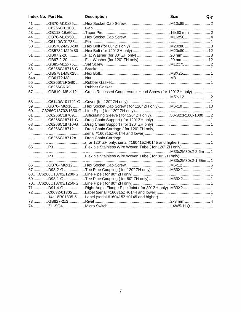
7
Index No. Part No. Description Size Qty
41 ............. GB70-M10x85 .......... Hex Socket Cap Screw ........................................ M10x85 ....................... 2 42 ............. C6266C01103 .......... Gap ...................................................................... .................................... 1 43 ............. GB118-16x60 ........... Taper Pin .............................................................. 16x60 mm ................... 2 44 ............. GB70-M16x50 .......... Hex Socket Cap Screw ........................................ M16x50 ....................... 4 49 ............. C6140W01733 ......... Pin ........................................................................ .................................... 1 50 ............. GB5782-M20x80 ...... Hex Bolt (for 80” ZH only) .................................... M20x80 ....................... 8 ................. GB5782-M20x80 ...... Hex Bolt (for 120” ZH only) .................................. M20x80 ..................... 12 51 ............. GB97.2-20 ................ Flat Washer (for 80” ZH only) .............................. 20 mm ......................... 8 ................. GB97.2-20 ................ Flat Washer (for 120” ZH only) ............................ 20 mm ....................... 12 52 ............. GB85-M12x75 .......... Set Screw ............................................................. M12x75 ....................... 2 53 ............. C6266C18716-G ...... Bracket ................................................................. .................................... 1 54 ............. GB5781-M8X25 ....... Hex Bolt ................................................................ M8X25......................... 1 54a ........... GB6172-M8 .............. Nut ........................................................................ M8 ............................... 1 55 ............. C6266CLRG80 ........ Rubber Gasket ..................................................... .................................... 1 56 ............. C6266CRRG ............ Rubber Gasket ..................................................... .................................... 1 57 ............. GB819- M5×12 ....... Cross Recessed Countersunk Head Screw (for 120” ZH only) .................. ................. ................................. ............................................................................. M5×12 ....................... 2 58 ............. C6140W-01721-G .... Cover (for 120” ZH only) ...................................... .................................... 1 59 ............. GB70- M6x10 ........... Hex Socket Cap Screw ( for 120” ZH only) .......... M6x10 ....................... 10 60…….C6266C18702/1650-G ... Line Pipe ( for 120” ZH only) ................................ .................................... 1 61 ............. C6266C18709 .......... Articulating Sleeve ( for 120” ZH only) ................. 50x82xR100x1000 ...... 2 62 ............. C6266C18711-G ...... Drag Chain Support ( for 120” ZH only) ............... .................................... 1 63 ............. C6266C18710-G ...... Drag Chain Support ( for 120” ZH only) ............... .................................... 1 64 ............. C6266C18712 .......... Drag Chain Carriage ( for 120” ZH only, ................. ................................. serial #160315ZH0144 and lower) ....................... .................................... 1 ................. C6266C18712A ....... Drag Chain Carriage ................. ................................. ( for 120” ZH only, serial #160415ZH0145 and higher) ............................ 1 65 ............. P3 ............................. Flexible Stainless Wire Woven Tube ( for 120” ZH only) ............................ ................. ................................. ............................................................................. M33x2M30x2-2.6m ..... 1 ................. P3 ............................. Flexible Stainless Wire Woven Tube ( for 80” ZH only) .............................. ................. ................................. ............................................................................. M33x2M30x2-1.65m ... 1 66 ............. GB70- M6x12 ........... Hex Socket Cap Screw ........................................ M6x12 ......................... 6 67 ............. D93-2-G ................... Tee Pipe Coupling ( for 120” ZH only) ................. M33X2......................... 1 68…..C6266C18702/1200-G ..... Line Pipe ( for 80” ZH only) .................................. .................................... 1 69 ............. D93-1-G ................... Tee Pipe Coupling ( for 80” ZH only) ................... M33X2......................... 1 70…..C6266C18703/1250-G ..... Line Pipe ( for 80” ZH only) .................................. .................................... 1 71 ............. D91-4-G ................... Right Angle Flange Pipe Joint ( for 80” ZH only) M33X2......................... 1 72 ............. C0632-01305 ........... Label (serial #160315ZH0144 and lower) ............ .................................... 1 ................. 14~18R01305-5 ....... Label (serial #160415ZH0145 and higher) .......... .................................... 1 73 ............. GB827-2x3 ............... Rivet ..................................................................... 2x3 mm ....................... 4 74 ............. ZH-SQ4 .................... Micro Switch ......................................................... LXW5-11Q1 ................ 1
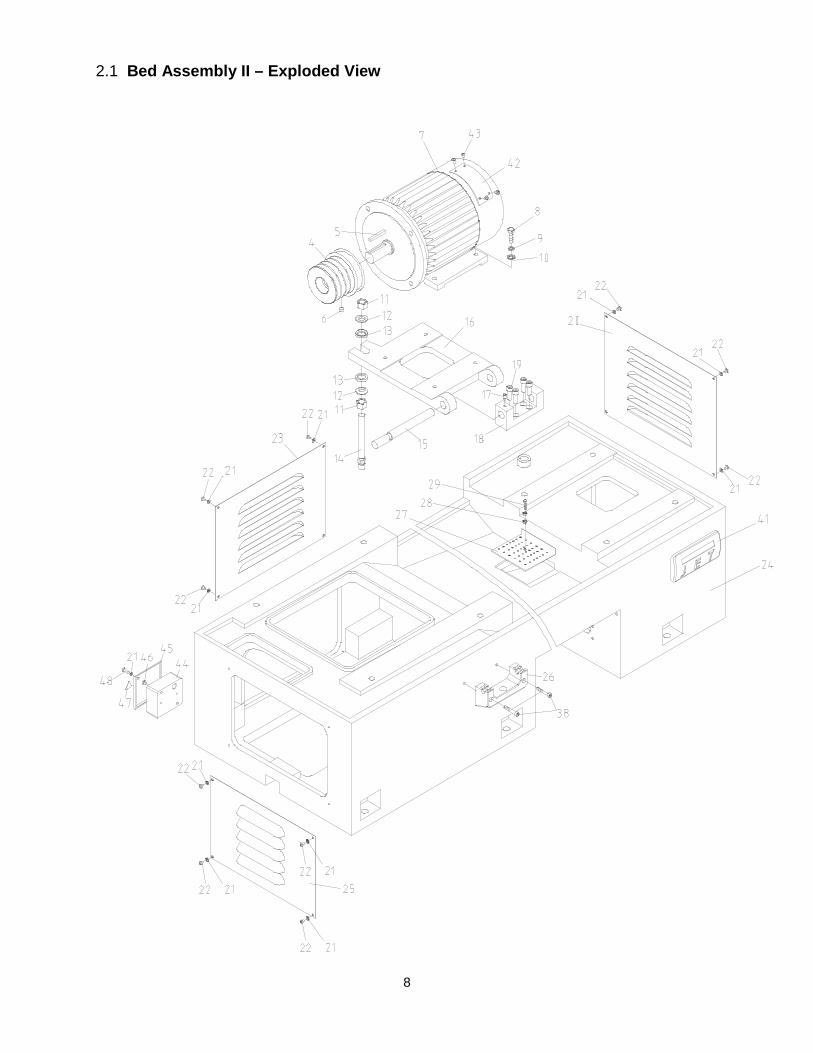
8
2.1 Bed Assembly II – Exploded View
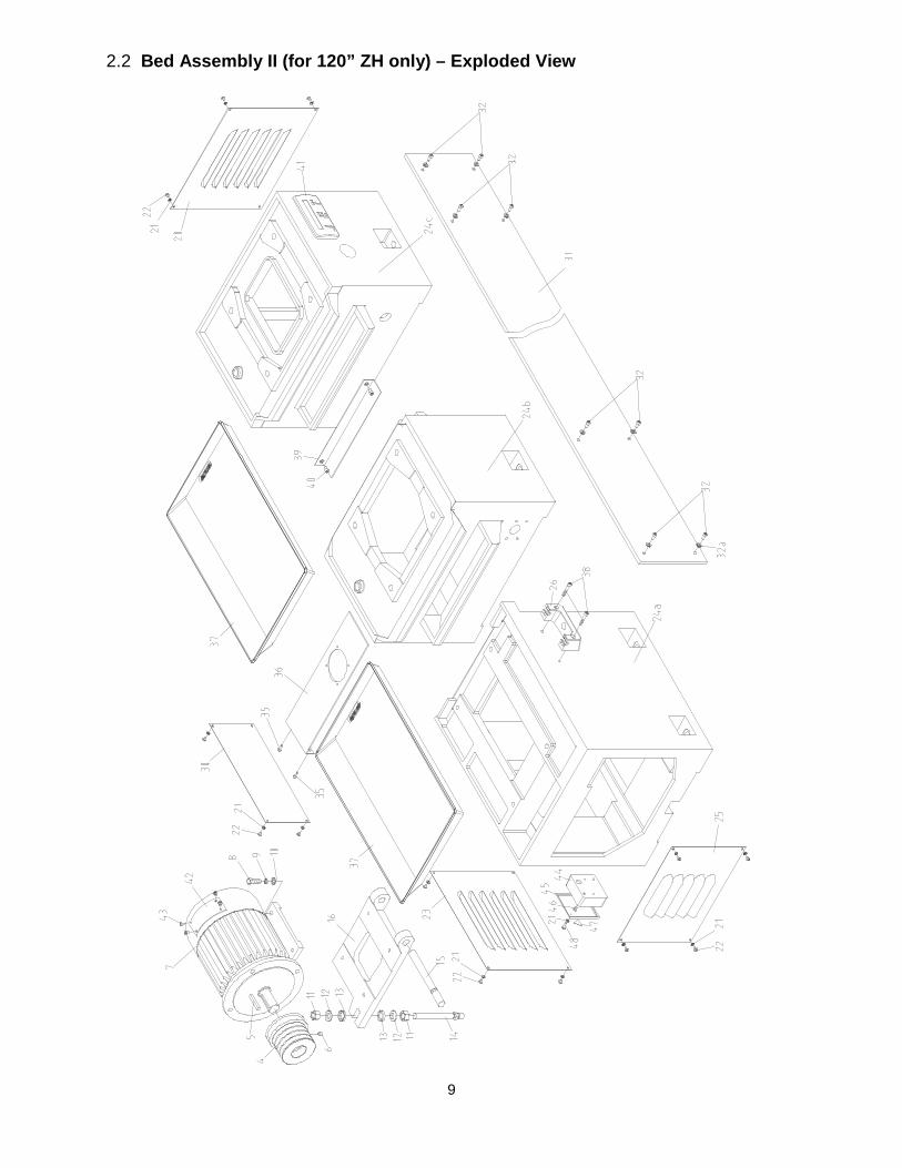
9
2.2 Bed Assembly II (for 120” ZH only) – Exploded View
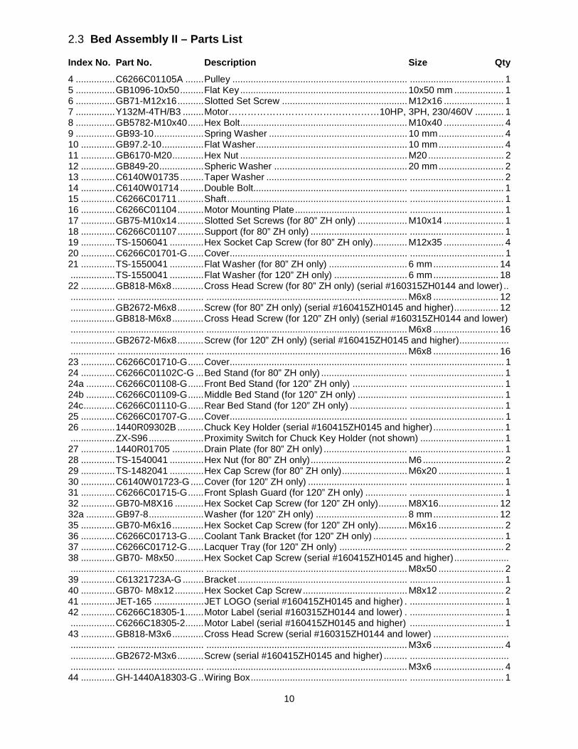
10
2.3 Bed Assembly II – Parts List
Index No. Part No. Description Size Qty
4 ............... C6266C01105A ....... Pulley ................................................................... .................................... 1 5 ............... GB1096-10x50 ......... Flat Key ................................................................ 10x50 mm ................... 1 6 ............... GB71-M12x16 .......... Slotted Set Screw ................................................ M12x16 ....................... 1 7 ............... Y132M-4TH/B3 ........ Motor…………………………………………10HP, 3PH, 230/460V ........... 1 8 ............... GB5782-M10x40 ...... Hex Bolt ................................................................ M10x40 ....................... 4 9 ............... GB93-10 ................... Spring Washer ..................................................... 10 mm ......................... 4 10 ............. GB97.2-10 ................ Flat Washer .......................................................... 10 mm ......................... 4 11 ............. GB6170-M20 ............ Hex Nut ................................................................ M20 ............................. 2 12 ............. GB849-20 ................. Spheric Washer ................................................... 20 mm ......................... 2 13 ............. C6140W01735 ......... Taper Washer ...................................................... .................................... 2 14 ............. C6140W01714 ......... Double Bolt........................................................... .................................... 1 15 ............. C6266C01711 .......... Shaft ..................................................................... .................................... 1 16 ............. C6266C01104 .......... Motor Mounting Plate ........................................... .................................... 1 17 ............. GB75-M10x14 .......... Slotted Set Screws (for 80” ZH only) ................... M10x14 ....................... 1 18 ............. C6266C01107 .......... Support (for 80” ZH only) ..................................... .................................... 1 19 ............. TS-1506041 ............. Hex Socket Cap Screw (for 80” ZH only) ............. M12x35 ....................... 4 20 ............. C6266C01701-G ...... Cover .................................................................... .................................... 1 21 ............. TS-1550041 ............. Flat Washer (for 80” ZH only) .............................. 6 mm ......................... 14 ................. TS-1550041 ............. Flat Washer (for 120” ZH only) ............................ 6 mm ......................... 18 22 ............. GB818-M6x8 ............ Cross Head Screw (for 80” ZH only) (serial #160315ZH0144 and lower) .. ................. ................................. ............................................................................. M6x8 ......................... 12 ................. GB2672-M6x8 .......... Screw (for 80” ZH only) (serial #160415ZH0145 and higher) ................. 12 ................. GB818-M6x8 ............ Cross Head Screw (for 120” ZH only) (serial #160315ZH0144 and lower) ................. ................................. ............................................................................. M6x8 ......................... 16 ................. GB2672-M6x8 .......... Screw (for 120” ZH only) (serial #160415ZH0145 and higher) ................... ................. ................................. ............................................................................. M6x8 ......................... 16 23 ............. C6266C01710-G ...... Cover .................................................................... .................................... 1 24 ............. C6266C01102C-G ... Bed Stand (for 80” ZH only) ................................. .................................... 1 24a ........... C6266C01108-G ...... Front Bed Stand (for 120” ZH only) ..................... .................................... 1 24b ........... C6266C01109-G ...... Middle Bed Stand (for 120” ZH only) ................... .................................... 1 24c ............ C6266C01110-G ...... Rear Bed Stand (for 120” ZH only) ...................... .................................... 1 25 ............. C6266C01707-G ...... Cover .................................................................... .................................... 1 26 ............. 1440R09302B .......... Chuck Key Holder (serial #160415ZH0145 and higher) ........................... 1 ................. ZX-S96 ..................... Proximity Switch for Chuck Key Holder (not shown) ................................ 1 27 ............. 1440R01705 ............ Drain Plate (for 80” ZH only) ................................ .................................... 1 28 ............. TS-1540041 ............. Hex Nut (for 80” ZH only) ..................................... M6 ............................... 2 29 ............. TS-1482041 ............. Hex Cap Screw (for 80” ZH only) ......................... M6x20 ......................... 1 30 ............. C6140W01723-G ..... Cover (for 120” ZH only) ...................................... .................................... 1 31 ............. C6266C01715-G ...... Front Splash Guard (for 120” ZH only) ................ .................................... 1 32 ............. GB70-M8X16 ........... Hex Socket Cap Screw (for 120” ZH only) ........... M8X16....................... 12 32a ........... GB97-8 ..................... Washer (for 120” ZH only) ................................... 8 mm ......................... 12 35 ............. GB70-M6x16 ............ Hex Socket Cap Screw (for 120” ZH only) ........... M6x16 ......................... 2 36 ............. C6266C01713-G ...... Coolant Tank Bracket (for 120” ZH only) ............. .................................... 1 37 ............. C6266C01712-G ...... Lacquer Tray (for 120” ZH only) .......................... .................................... 2 38 ............. GB70- M8x50 ........... Hex Socket Cap Screw (serial #160415ZH0145 and higher) ..................... ................. ................................. ............................................................................. M8x50 ......................... 2 39 ............. C61321723A-G ........ Bracket ................................................................. .................................... 1 40 ............. GB70- M8x12 ........... Hex Socket Cap Screw ........................................ M8x12 ......................... 2 41 ............. JET-165 ................... JET LOGO (serial #160415ZH0145 and higher) . .................................... 1 42 ............. C6266C18305-1 ....... Motor Label (serial #160315ZH0144 and lower) . .................................... 1 ................. C6266C18305-2 ....... Motor Label (serial #160415ZH0145 and higher) .................................... 1 43 ............. GB818-M3x6 ............ Cross Head Screw (serial #160315ZH0144 and lower) ............................. ................. ................................. ............................................................................. M3x6 ........................... 4 ................. GB2672-M3x6 .......... Screw (serial #160415ZH0145 and higher) ......... ...................................... ................. ................................. ............................................................................. M3x6 ........................... 4 44 ............. GH-1440A18303-G .. Wiring Box ............................................................ .................................... 1

11
Index No. Part No. Description Size Qty
45 ............. GH-1440A18304-G .. Wiring Box Cover ................................................. .................................... 1 46 ............. GB818-M6x8 ............ Cross Head Screw ............................................... M6x8 ........................... 2 47 ............. C613618302 ............ Warning Label ...................................................... .................................... 1 48 ............. GB2672-M6x20 ........ Screw ................................................................... M6x20 ......................... 2
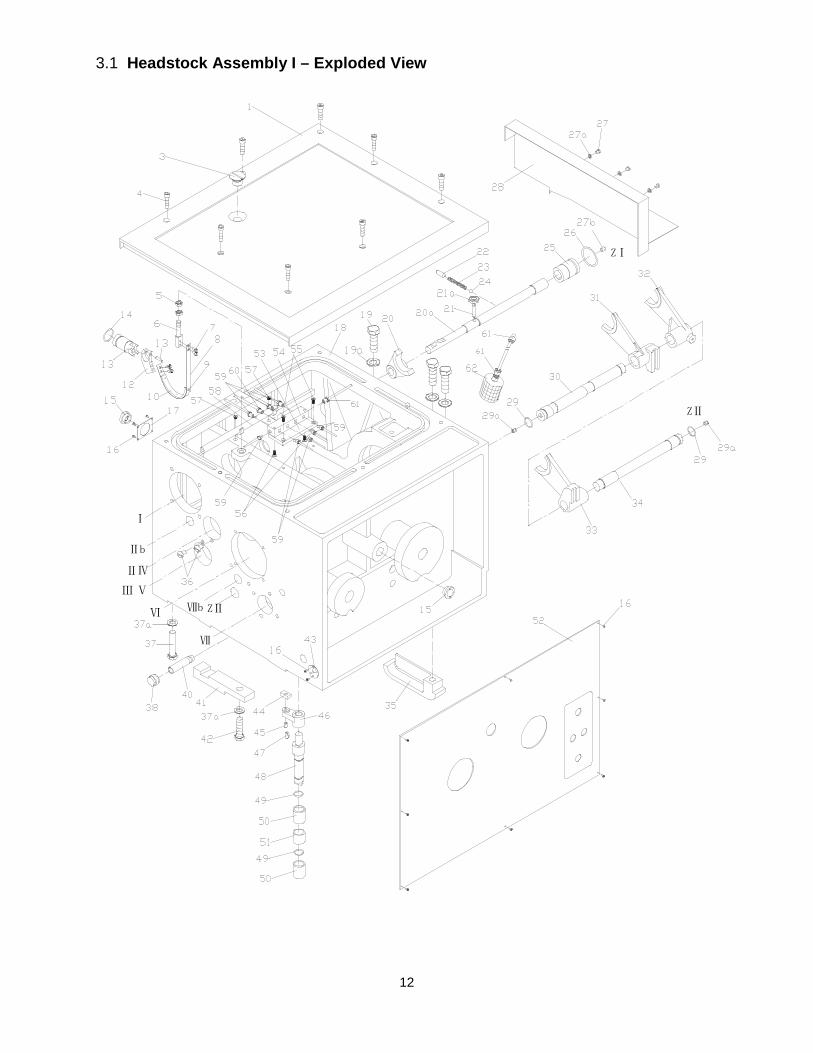
12
3.1 Headstock Assembly I – Exploded View
Ⅲ
Ⅳ
Ⅴ
Ⅶ
Ⅵ
Ⅱ
Ⅰ
Ⅱb
Ⅶb ZⅡ
ZⅠ
ZⅡ
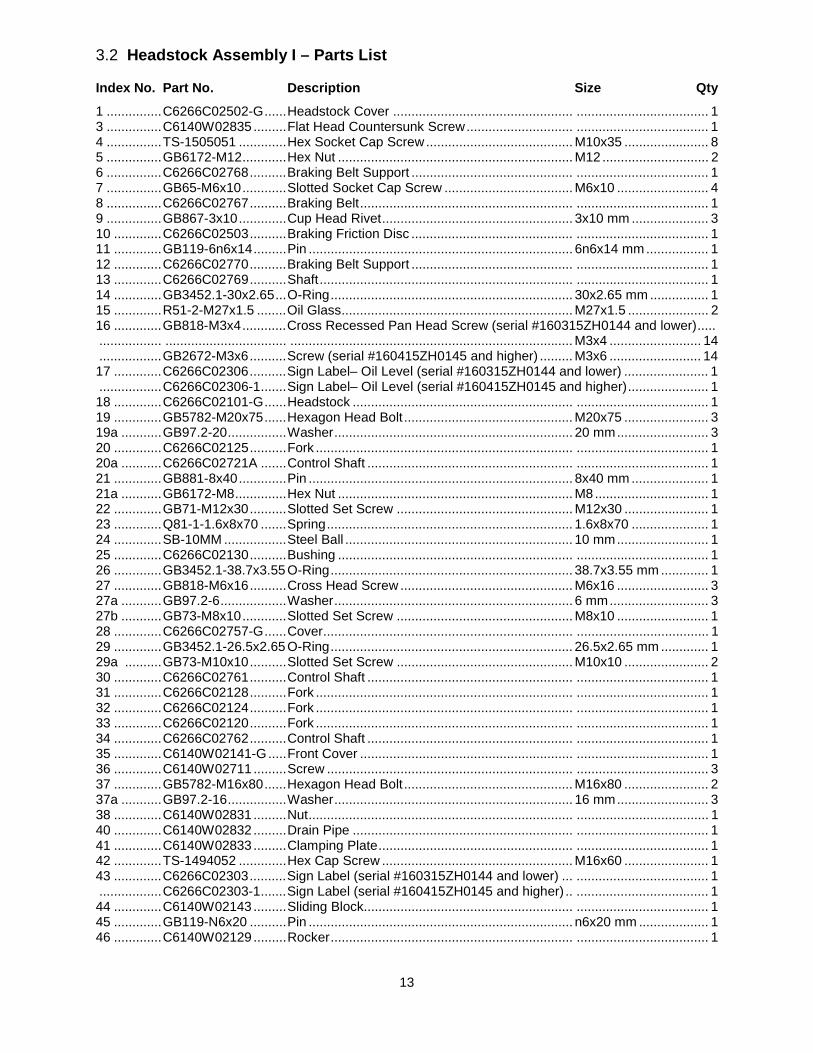
13
3.2 Headstock Assembly I – Parts List
Index No. Part No. Description Size Qty
1 ............... C6266C02502-G ...... Headstock Cover ................................................. .................................... 1 3 ............... C6140W02835 ......... Flat Head Countersunk Screw ............................. .................................... 1 4 ............... TS-1505051 ............. Hex Socket Cap Screw ........................................ M10x35 ....................... 8 5 ............... GB6172-M12 ............ Hex Nut ................................................................ M12 ............................. 2 6 ............... C6266C02768 .......... Braking Belt Support ............................................ .................................... 1 7 ............... GB65-M6x10 ............ Slotted Socket Cap Screw ................................... M6x10 ......................... 4 8 ............... C6266C02767 .......... Braking Belt .......................................................... .................................... 1 9 ............... GB867-3x10 ............. Cup Head Rivet .................................................... 3x10 mm ..................... 3 10 ............. C6266C02503 .......... Braking Friction Disc ............................................ .................................... 1 11 ............. GB119-6n6x14 ......... Pin ........................................................................ 6n6x14 mm ................. 1 12 ............. C6266C02770 .......... Braking Belt Support ............................................ .................................... 1 13 ............. C6266C02769 .......... Shaft ..................................................................... .................................... 1 14 ............. GB3452.1-30x2.65 ... O-Ring .................................................................. 30x2.65 mm ................ 1 15 ............. R51-2-M27x1.5 ........ Oil Glass ............................................................... M27x1.5 ...................... 2 16 ............. GB818-M3x4 ............ Cross Recessed Pan Head Screw (serial #160315ZH0144 and lower) ..... ................. ................................. ............................................................................. M3x4 ......................... 14 ................. GB2672-M3x6 .......... Screw (serial #160415ZH0145 and higher) ......... M3x6 ......................... 14 17 ............. C6266C02306 .......... Sign Label– Oil Level (serial #160315ZH0144 and lower) ....................... 1 ................. C6266C02306-1 ....... Sign Label– Oil Level (serial #160415ZH0145 and higher) ...................... 1 18 ............. C6266C02101-G ...... Headstock ............................................................ .................................... 1 19 ............. GB5782-M20x75 ...... Hexagon Head Bolt .............................................. M20x75 ....................... 3 19a ........... GB97.2-20 ................ Washer ................................................................. 20 mm ......................... 3 20 ............. C6266C02125 .......... Fork ...................................................................... .................................... 1 20a ........... C6266C02721A ....... Control Shaft ........................................................ .................................... 1 21 ............. GB881-8x40 ............. Pin ........................................................................ 8x40 mm ..................... 1 21a ........... GB6172-M8 .............. Hex Nut ................................................................ M8 ............................... 1 22 ............. GB71-M12x30 .......... Slotted Set Screw ................................................ M12x30 ....................... 1 23 ............. Q81-1-1.6x8x70 ....... Spring ................................................................... 1.6x8x70 ..................... 1 24 ............. SB-10MM ................. Steel Ball .............................................................. 10 mm ......................... 1 25 ............. C6266C02130 .......... Bushing ................................................................ .................................... 1 26 ............. GB3452.1-38.7x3.55 O-Ring .................................................................. 38.7x3.55 mm ............. 1 27 ............. GB818-M6x16 .......... Cross Head Screw ............................................... M6x16 ......................... 3 27a ........... GB97.2-6 .................. Washer ................................................................. 6 mm ........................... 3 27b ........... GB73-M8x10 ............ Slotted Set Screw ................................................ M8x10 ......................... 1 28 ............. C6266C02757-G ...... Cover .................................................................... .................................... 1 29 ............. GB3452.1-26.5x2.65 O-Ring .................................................................. 26.5x2.65 mm ............. 1 29a .......... GB73-M10x10 .......... Slotted Set Screw ................................................ M10x10 ....................... 2 30 ............. C6266C02761 .......... Control Shaft ........................................................ .................................... 1 31 ............. C6266C02128 .......... Fork ...................................................................... .................................... 1 32 ............. C6266C02124 .......... Fork ...................................................................... .................................... 1 33 ............. C6266C02120 .......... Fork ...................................................................... .................................... 1 34 ............. C6266C02762 .......... Control Shaft ........................................................ .................................... 1 35 ............. C6140W02141-G ..... Front Cover .......................................................... .................................... 1 36 ............. C6140W02711 ......... Screw ................................................................... .................................... 3 37 ............. GB5782-M16x80 ...... Hexagon Head Bolt .............................................. M16x80 ....................... 2 37a ........... GB97.2-16 ................ Washer ................................................................. 16 mm ......................... 3 38 ............. C6140W02831 ......... Nut ........................................................................ .................................... 1 40 ............. C6140W02832 ......... Drain Pipe ............................................................ .................................... 1 41 ............. C6140W02833 ......... Clamping Plate ..................................................... .................................... 1 42 ............. TS-1494052 ............. Hex Cap Screw .................................................... M16x60 ....................... 1 43 ............. C6266C02303 .......... Sign Label (serial #160315ZH0144 and lower) ... .................................... 1 ................. C6266C02303-1 ....... Sign Label (serial #160415ZH0145 and higher) .. .................................... 1 44 ............. C6140W02143 ......... Sliding Block......................................................... .................................... 1 45 ............. GB119-N6x20 .......... Pin ........................................................................ n6x20 mm ................... 1 46 ............. C6140W02129 ......... Rocker .................................................................. .................................... 1
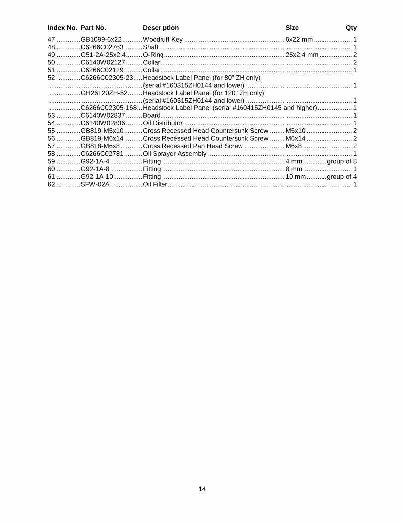
14
Index No. Part No. Description Size Qty
47 ............. GB1099-6x22 ........... Woodruff Key ....................................................... 6x22 mm ..................... 1 48 ............. C6266C02763 .......... Shaft ..................................................................... .................................... 1 49 ............. G51-2A-25x2.4 ......... O-Ring .................................................................. 25x2.4 mm .................. 2 50 ............. C6140W02127 ......... Collar .................................................................... .................................... 2 51 ............. C6266C02119 .......... Collar .................................................................... .................................... 1 52 ............ C6266C02305-23 ..... Headstock Label Panel (for 80” ZH only) ................. ................................. (serial #160315ZH0144 and lower) ..................... .................................... 1 ................. GH26120ZH-52 ........ Headstock Label Panel (for 120” ZH only) ................. ................................. (serial #160315ZH0144 and lower) ..................... .................................... 1 ................. C6266C02305-168 ... Headstock Label Panel (serial #160415ZH0145 and higher) ................... 1 53 ............. C6140W02837 ......... Board .................................................................... .................................... 1 54 ............. C6140W02836 ......... Oil Distributor ....................................................... .................................... 1 55 ............. GB819-M5x10 .......... Cross Recessed Head Countersunk Screw ........ M5x10 ......................... 2 56 ............. GB819-M6x14 .......... Cross Recessed Head Countersunk Screw ........ M6x14 ......................... 2 57 ............. GB818-M6x8 ............ Cross Recessed Pan Head Screw ...................... M6x8 ........................... 2 58 ............. C6266C02781 .......... Oil Sprayer Assembly .......................................... .................................... 1 59 ............. G92-1A-4 ................. Fitting ................................................................... 4 mm ............. group of 8 60 ............. G92-1A-8 ................. Fitting ................................................................... 8 mm ........................... 1 61 ............. G92-1A-10 ............... Fitting ................................................................... 10 mm ........... group of 4 62 ............. SFW-02A ................. Oil Filter ................................................................ .................................... 1
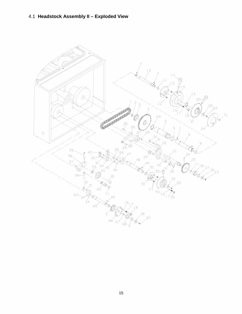
15
4.1 Headstock Assembly II – Exploded View
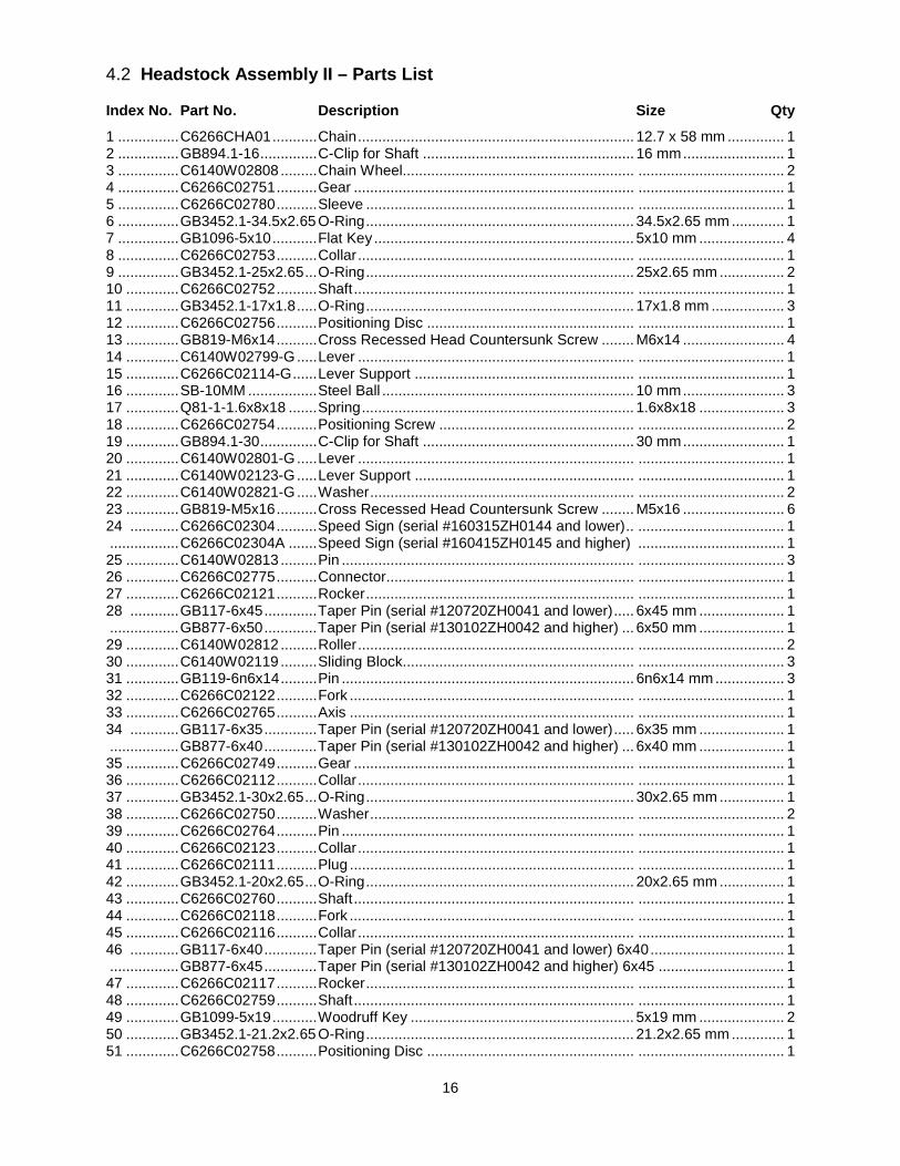
16
4.2 Headstock Assembly II – Parts List
Index No. Part No. Description Size Qty
1 ............... C6266CHA01 ........... Chain .................................................................... 12.7 x 58 mm .............. 1 2 ............... GB894.1-16 .............. C-Clip for Shaft .................................................... 16 mm ......................... 1 3 ............... C6140W02808 ......... Chain Wheel......................................................... .................................... 2 4 ............... C6266C02751 .......... Gear ..................................................................... .................................... 1 5 ............... C6266C02780 .......... Sleeve .................................................................. .................................... 1 6 ............... GB3452.1-34.5x2.65 O-Ring .................................................................. 34.5x2.65 mm ............. 1 7 ............... GB1096-5x10 ........... Flat Key ................................................................ 5x10 mm ..................... 4 8 ............... C6266C02753 .......... Collar .................................................................... .................................... 1 9 ............... GB3452.1-25x2.65 ... O-Ring .................................................................. 25x2.65 mm ................ 2 10 ............. C6266C02752 .......... Shaft ..................................................................... .................................... 1 11 ............. GB3452.1-17x1.8 ..... O-Ring .................................................................. 17x1.8 mm .................. 3 12 ............. C6266C02756 .......... Positioning Disc ................................................... .................................... 1 13 ............. GB819-M6x14 .......... Cross Recessed Head Countersunk Screw ........ M6x14 ......................... 4 14 ............. C6140W02799-G ..... Lever .................................................................... .................................... 1 15 ............. C6266C02114-G ...... Lever Support ...................................................... .................................... 1 16 ............. SB-10MM ................. Steel Ball .............................................................. 10 mm ......................... 3 17 ............. Q81-1-1.6x8x18 ....... Spring ................................................................... 1.6x8x18 ..................... 3 18 ............. C6266C02754 .......... Positioning Screw ................................................ .................................... 2 19 ............. GB894.1-30 .............. C-Clip for Shaft .................................................... 30 mm ......................... 1 20 ............. C6140W02801-G ..... Lever .................................................................... .................................... 1 21 ............. C6140W02123-G ..... Lever Support ...................................................... .................................... 1 22 ............. C6140W02821-G ..... Washer ................................................................. .................................... 2 23 ............. GB819-M5x16 .......... Cross Recessed Head Countersunk Screw ........ M5x16 ......................... 6 24 ............ C6266C02304 .......... Speed Sign (serial #160315ZH0144 and lower) .. .................................... 1 ................. C6266C02304A ....... Speed Sign (serial #160415ZH0145 and higher) .................................... 1 25 ............. C6140W02813 ......... Pin ........................................................................ .................................... 3 26 ............. C6266C02775 .......... Connector............................................................. .................................... 1 27 ............. C6266C02121 .......... Rocker .................................................................. .................................... 1 28 ............ GB117-6x45 ............. Taper Pin (serial #120720ZH0041 and lower) ..... 6x45 mm ..................... 1 ................. GB877-6x50 ............. Taper Pin (serial #130102ZH0042 and higher) ... 6x50 mm ..................... 1 29 ............. C6140W02812 ......... Roller .................................................................... .................................... 2 30 ............. C6140W02119 ......... Sliding Block......................................................... .................................... 3 31 ............. GB119-6n6x14 ......... Pin ........................................................................ 6n6x14 mm ................. 3 32 ............. C6266C02122 .......... Fork ...................................................................... .................................... 1 33 ............. C6266C02765 .......... Axis ...................................................................... .................................... 1 34 ............ GB117-6x35 ............. Taper Pin (serial #120720ZH0041 and lower) ..... 6x35 mm ..................... 1 ................. GB877-6x40 ............. Taper Pin (serial #130102ZH0042 and higher) ... 6x40 mm ..................... 1 35 ............. C6266C02749 .......... Gear ..................................................................... .................................... 1 36 ............. C6266C02112 .......... Collar .................................................................... .................................... 1 37 ............. GB3452.1-30x2.65 ... O-Ring .................................................................. 30x2.65 mm ................ 1 38 ............. C6266C02750 .......... Washer ................................................................. .................................... 2 39 ............. C6266C02764 .......... Pin ........................................................................ .................................... 1 40 ............. C6266C02123 .......... Collar .................................................................... .................................... 1 41 ............. C6266C02111 .......... Plug ...................................................................... .................................... 1 42 ............. GB3452.1-20x2.65 ... O-Ring .................................................................. 20x2.65 mm ................ 1 43 ............. C6266C02760 .......... Shaft ..................................................................... .................................... 1 44 ............. C6266C02118 .......... Fork ...................................................................... .................................... 1 45 ............. C6266C02116 .......... Collar .................................................................... .................................... 1 46 ............ GB117-6x40 ............. Taper Pin (serial #120720ZH0041 and lower) 6x40 ................................. 1 ................. GB877-6x45 ............. Taper Pin (serial #130102ZH0042 and higher) 6x45 ............................... 1 47 ............. C6266C02117 .......... Rocker .................................................................. .................................... 1 48 ............. C6266C02759 .......... Shaft ..................................................................... .................................... 1 49 ............. GB1099-5x19 ........... Woodruff Key ....................................................... 5x19 mm ..................... 2 50 ............. GB3452.1-21.2x2.65 O-Ring .................................................................. 21.2x2.65 mm ............. 1 51 ............. C6266C02758 .......... Positioning Disc ................................................... .................................... 1
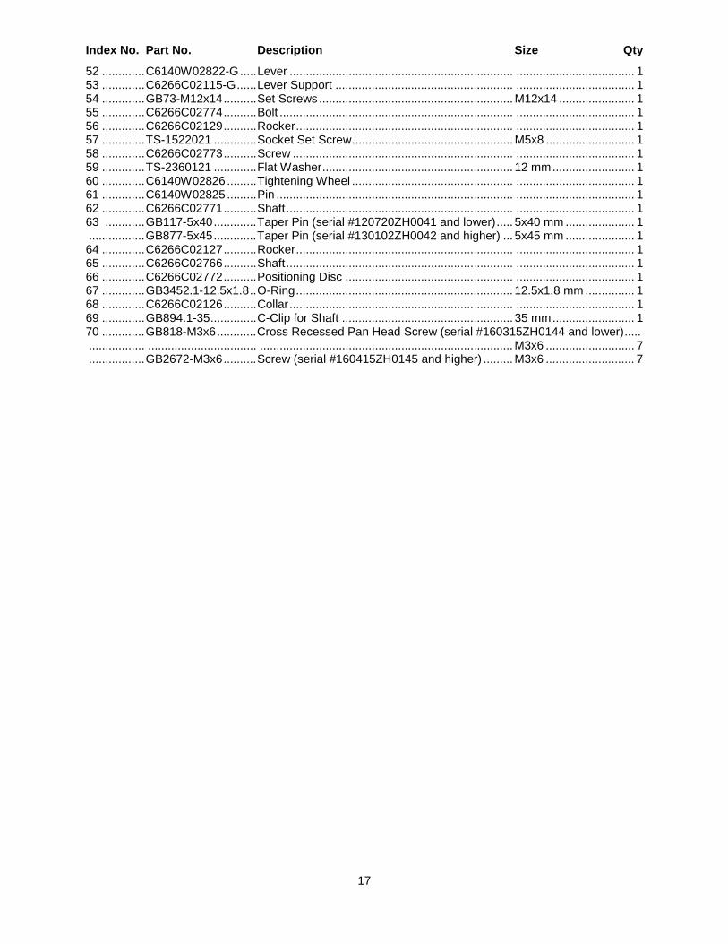
17
Index No. Part No. Description Size Qty
52 ............. C6140W02822-G ..... Lever .................................................................... .................................... 1 53 ............. C6266C02115-G ...... Lever Support ...................................................... .................................... 1 54 ............. GB73-M12x14 .......... Set Screws ........................................................... M12x14 ....................... 1 55 ............. C6266C02774 .......... Bolt ....................................................................... .................................... 1 56 ............. C6266C02129 .......... Rocker .................................................................. .................................... 1 57 ............. TS-1522021 ............. Socket Set Screw ................................................. M5x8 ........................... 1 58 ............. C6266C02773 .......... Screw ................................................................... .................................... 1 59 ............. TS-2360121 ............. Flat Washer .......................................................... 12 mm ......................... 1 60 ............. C6140W02826 ......... Tightening Wheel ................................................. .................................... 1 61 ............. C6140W02825 ......... Pin ........................................................................ .................................... 1 62 ............. C6266C02771 .......... Shaft ..................................................................... .................................... 1 63 ............ GB117-5x40 ............. Taper Pin (serial #120720ZH0041 and lower) ..... 5x40 mm ..................... 1 ................. GB877-5x45 ............. Taper Pin (serial #130102ZH0042 and higher) ... 5x45 mm ..................... 1 64 ............. C6266C02127 .......... Rocker .................................................................. .................................... 1 65 ............. C6266C02766 .......... Shaft ..................................................................... .................................... 1 66 ............. C6266C02772 .......... Positioning Disc ................................................... .................................... 1 67 ............. GB3452.1-12.5x1.8 .. O-Ring .................................................................. 12.5x1.8 mm ............... 1 68 ............. C6266C02126 .......... Collar .................................................................... .................................... 1 69 ............. GB894.1-35 .............. C-Clip for Shaft .................................................... 35 mm ......................... 1 70 ............. GB818-M3x6 ............ Cross Recessed Pan Head Screw (serial #160315ZH0144 and lower) ..... ................. ................................. ............................................................................. M3x6 ........................... 7 ................. GB2672-M3x6 .......... Screw (serial #160415ZH0145 and higher) ......... M3x6 ........................... 7
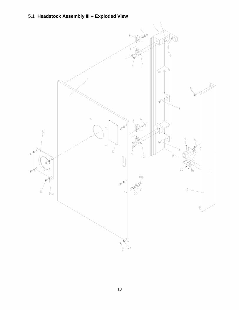
18
5.1 Headstock Assembly III – Exploded View
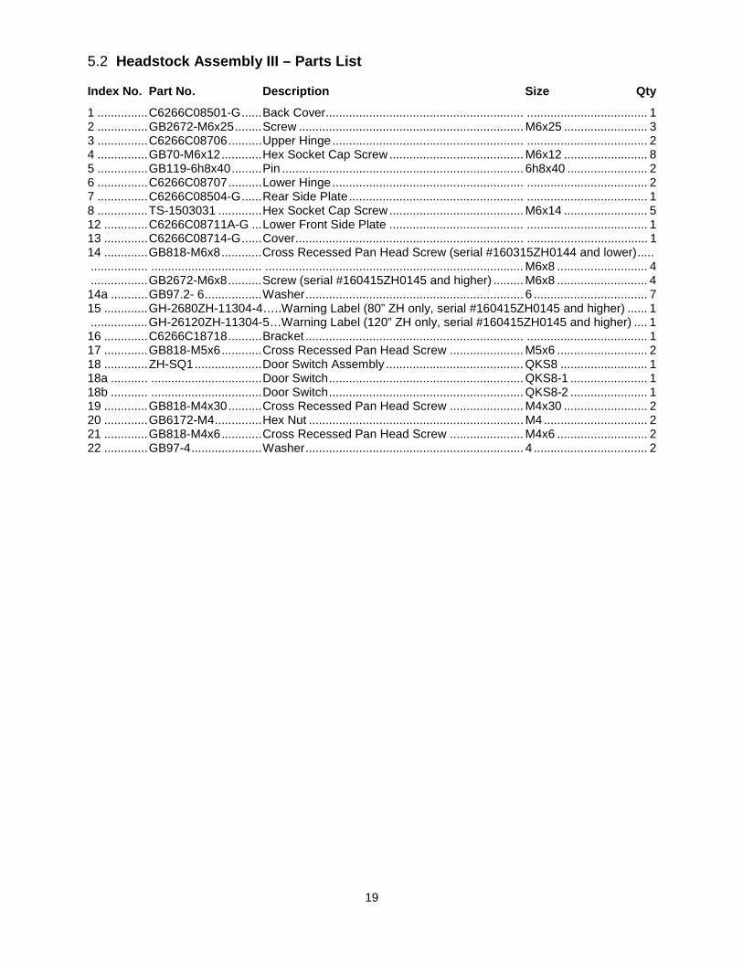
19
5.2 Headstock Assembly III – Parts List
Index No. Part No. Description Size Qty
1 ............... C6266C08501-G ...... Back Cover........................................................... .................................... 1 2 ............... GB2672-M6x25 ........ Screw ................................................................... M6x25 ......................... 3 3 ............... C6266C08706 .......... Upper Hinge ......................................................... .................................... 2 4 ............... GB70-M6x12 ............ Hex Socket Cap Screw ........................................ M6x12 ......................... 8 5 ............... GB119-6h8x40 ......... Pin ........................................................................ 6h8x40 ........................ 2 6 ............... C6266C08707 .......... Lower Hinge ......................................................... .................................... 2 7 ............... C6266C08504-G ...... Rear Side Plate .................................................... .................................... 1 8 ............... TS-1503031 ............. Hex Socket Cap Screw ........................................ M6x14 ......................... 5 12 ............. C6266C08711A-G ... Lower Front Side Plate ........................................ .................................... 1 13 ............. C6266C08714-G ...... Cover .................................................................... .................................... 1 14 ............. GB818-M6x8 ............ Cross Recessed Pan Head Screw (serial #160315ZH0144 and lower) ..... ................. ................................. ............................................................................. M6x8 ........................... 4 ................. GB2672-M6x8 .......... Screw (serial #160415ZH0145 and higher) ......... M6x8 ........................... 4 14a ........... GB97.2- 6 ................. Washer ................................................................. 6 .................................. 7 15 ............. GH-2680ZH-11304-4…..Warning Label (80” ZH only, serial #160415ZH0145 and higher) ...... 1 ................. GH-26120ZH-11304-5…Warning Label (120” ZH only, serial #160415ZH0145 and higher) .... 1 16 ............. C6266C18718 .......... Bracket ................................................................. .................................... 1 17 ............. GB818-M5x6 ............ Cross Recessed Pan Head Screw ...................... M5x6 ........................... 2 18 ............. ZH-SQ1 .................... Door Switch Assembly ......................................... QKS8 .......................... 1 18a ........... ................................. Door Switch .......................................................... QKS8-1 ....................... 1 18b ........... ................................. Door Switch .......................................................... QKS8-2 ....................... 1 19 ............. GB818-M4x30 .......... Cross Recessed Pan Head Screw ...................... M4x30 ......................... 2 20 ............. GB6172-M4 .............. Hex Nut ................................................................ M4 ............................... 2 21 ............. GB818-M4x6 ............ Cross Recessed Pan Head Screw ...................... M4x6 ........................... 2 22 ............. GB97-4 ..................... Washer ................................................................. 4 .................................. 2
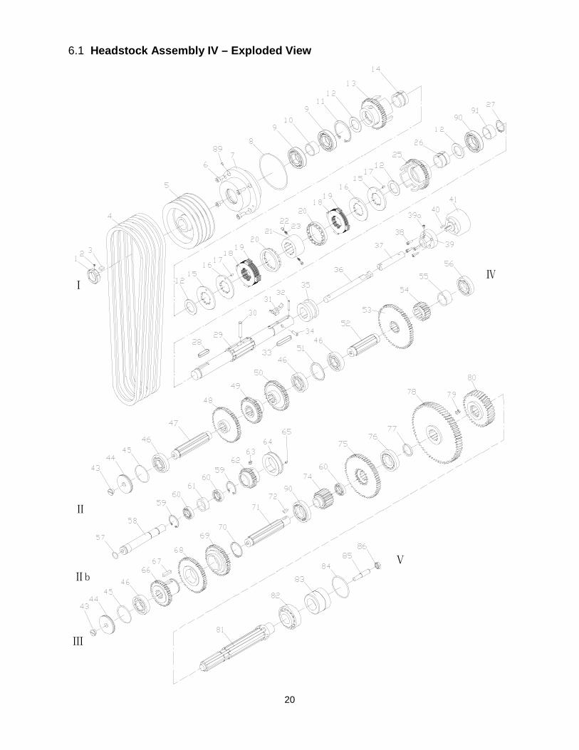
20
6.1 Headstock Assembly IV – Exploded View
Ⅰ
Ⅱb
Ⅱ
Ⅲ
Ⅳ
Ⅴ
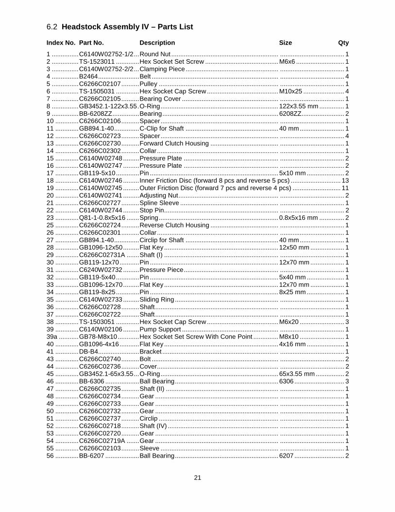
21
6.2 Headstock Assembly IV – Parts List
Index No. Part No. Description Size Qty
1 ............... C6140W02752-1/2 ... Round Nut ............................................................ .................................... 1 2 ............... TS-1523011 ............. Hex Socket Set Screw ......................................... M6x6 ........................... 1 3 ............... C6140W02752-2/2 ... Clamping Piece .................................................... .................................... 1 4 ............... B2464 ....................... Belt ....................................................................... .................................... 4 5 ............... C6266C02107 .......... Pulley ................................................................... .................................... 1 6 ............... TS-1505031 ............. Hex Socket Cap Screw ........................................ M10x25 ....................... 4 7 ............... C6266C02105 .......... Bearing Cover ...................................................... .................................... 1 8 ............... GB3452.1-122x3.55 . O-Ring .................................................................. 122x3.55 mm .............. 1 9 ............... BB-6208ZZ ............... Bearing ................................................................. 6208ZZ........................ 2 10 ............. C6266C02106 .......... Spacer .................................................................. .................................... 1 11 ............. GB894.1-40 .............. C-Clip for Shaft .................................................... 40 mm ......................... 1 12 ............. C6266C02723 .......... Spacer .................................................................. .................................... 4 13 ............. C6266C02730 .......... Forward Clutch Housing ...................................... .................................... 1 14 ............. C6266C02302 .......... Collar .................................................................... .................................... 1 15 ............. C6140W02748 ......... Pressure Plate ..................................................... .................................... 2 16 ............. C6140W02747 ......... Pressure Plate ..................................................... .................................... 2 17 ............. GB119-5x10 ............. Pin ........................................................................ 5x10 mm ..................... 2 18 ............. C6140W02746 ......... Inner Friction Disc (forward 8 pcs and reverse 5 pcs) ............................ 13 19 ............. C6140W02745 ......... Outer Friction Disc (forward 7 pcs and reverse 4 pcs) ........................... 11 20 ............. C6140W02741 ......... Adjusting Nut ........................................................ .................................... 2 21 ............. C6266C02727 .......... Spline Sleeve ....................................................... .................................... 1 22 ............. C6140W02744 ......... Stop Pin ................................................................ .................................... 2 23 ............. Q81-1-0.8x5x16 ....... Spring ................................................................... 0.8x5x16 mm .............. 2 25 ............. C6266C02724 .......... Reverse Clutch Housing ...................................... .................................... 1 26 ............. C6266C02301 .......... Collar .................................................................... .................................... 1 27 ............. GB894.1-40 .............. Circlip for Shaft .................................................... 40 mm ......................... 1 28 ............. GB1096-12x50 ......... Flat Key ................................................................ 12x50 mm ................... 1 29 ............. C6266C02731A ....... Shaft (I) ................................................................ .................................... 1 30 ............. GB119-12x70 ........... Pin ........................................................................ 12x70 mm ................... 1 31 ............. C6240W02732 ......... Pressure Piece ..................................................... .................................... 1 32 ............. GB119-5x40 ............. Pin ........................................................................ 5x40 mm ..................... 1 33 ............. GB1096-12x70 ......... Flat Key ................................................................ 12x70 mm ................... 1 34 ............. GB119-8x25 ............. Pin ........................................................................ 8x25 mm ..................... 1 35 ............. C6140W02733 ......... Sliding Ring .......................................................... .................................... 1 36 ............. C6266C02728 .......... Shaft ..................................................................... .................................... 1 37 ............. C6266C02722 .......... Shaft ..................................................................... .................................... 1 38 ............. TS-1503051 ............. Hex Socket Cap Screw ........................................ M6x20 ......................... 3 39 ............. C6140W02106 ......... Pump Support ...................................................... .................................... 1 39a ........... GB78-M8x10 ............ Hex Socket Set Screw With Cone Point .............. M8x10 ......................... 1 40 ............. GB1096-4x16 ........... Flat Key ................................................................ 4x16 mm ..................... 1 41 ............. DB-B4....................... Bracket ................................................................. .................................... 1 43 ............. C6266C02740 .......... Bolt ....................................................................... .................................... 2 44 ............. C6266C02736 .......... Cover .................................................................... .................................... 2 45 ............. GB3452.1-65x3.55 ... O-Ring .................................................................. 65x3.55 mm ................ 2 46 ............. BB-6306 ................... Ball Bearing .......................................................... 6306 ............................ 3 47 ............. C6266C02735 .......... Shaft (II) ............................................................... .................................... 1 48 ............. C6266C02734 .......... Gear ..................................................................... .................................... 1 49 ............. C6266C02733 .......... Gear ..................................................................... .................................... 1 50 ............. C6266C02732 .......... Gear ..................................................................... .................................... 1 51 ............. C6266C02737 .......... Circlip ................................................................... .................................... 1 52 ............. C6266C02718 .......... Shaft (IV) .............................................................. .................................... 1 53 ............. C6266C02720 .......... Gear ..................................................................... .................................... 1 54 ............. C6266C02719A ....... Gear ..................................................................... .................................... 1 55 ............. C6266C02103 .......... Sleeve .................................................................. .................................... 1 56 ............. BB-6207 ................... Ball Bearing .......................................................... 6207 ............................ 2
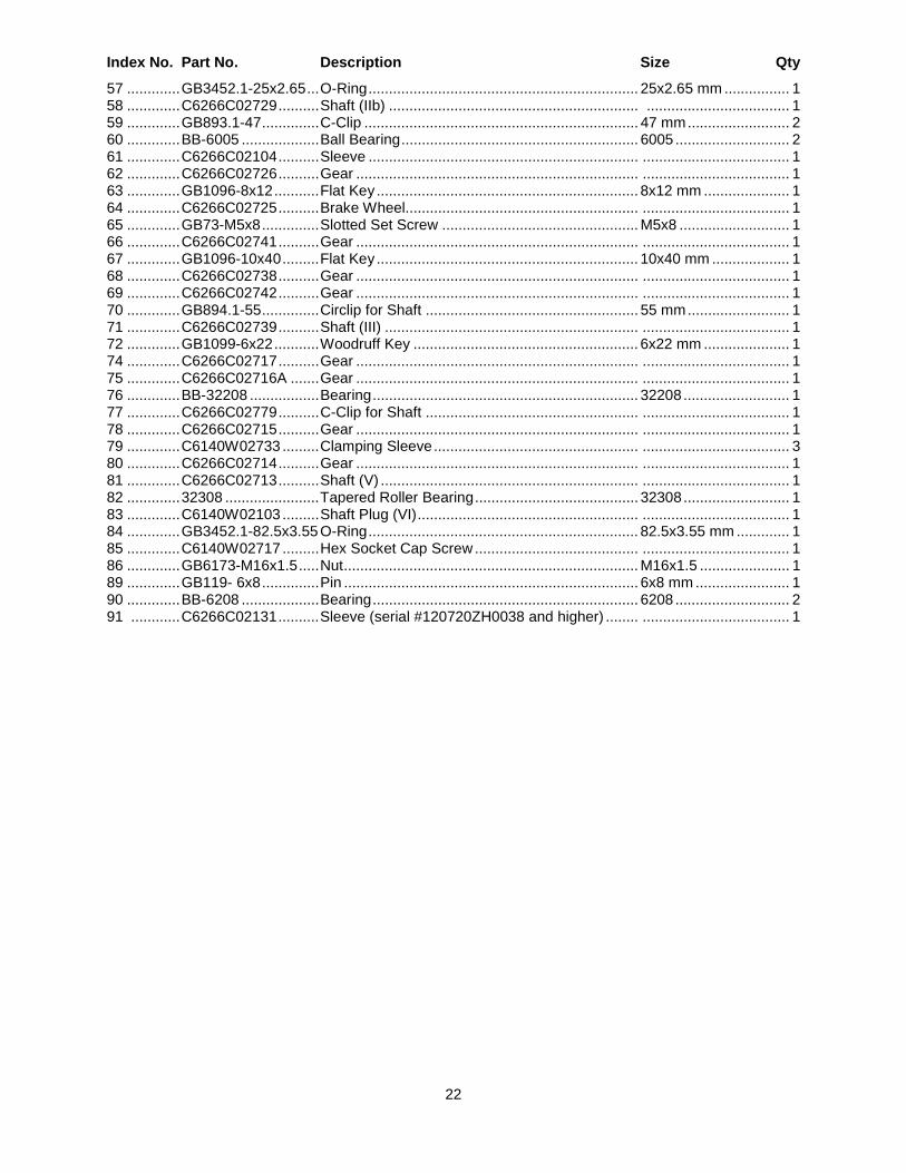
22
Index No. Part No. Description Size Qty
57 ............. GB3452.1-25x2.65 ... O-Ring .................................................................. 25x2.65 mm ................ 1 58 ............. C6266C02729 .......... Shaft (IIb) ............................................................. ................................... 1 59 ............. GB893.1-47 .............. C-Clip ................................................................... 47 mm ......................... 2 60 ............. BB-6005 ................... Ball Bearing .......................................................... 6005 ............................ 2 61 ............. C6266C02104 .......... Sleeve .................................................................. .................................... 1 62 ............. C6266C02726 .......... Gear ..................................................................... .................................... 1 63 ............. GB1096-8x12 ........... Flat Key ................................................................ 8x12 mm ..................... 1 64 ............. C6266C02725 .......... Brake Wheel......................................................... .................................... 1 65 ............. GB73-M5x8 .............. Slotted Set Screw ................................................ M5x8 ........................... 1 66 ............. C6266C02741 .......... Gear ..................................................................... .................................... 1 67 ............. GB1096-10x40 ......... Flat Key ................................................................ 10x40 mm ................... 1 68 ............. C6266C02738 .......... Gear ..................................................................... .................................... 1 69 ............. C6266C02742 .......... Gear ..................................................................... .................................... 1 70 ............. GB894.1-55 .............. Circlip for Shaft .................................................... 55 mm ......................... 1 71 ............. C6266C02739 .......... Shaft (III) .............................................................. .................................... 1 72 ............. GB1099-6x22 ........... Woodruff Key ....................................................... 6x22 mm ..................... 1 74 ............. C6266C02717 .......... Gear ..................................................................... .................................... 1 75 ............. C6266C02716A ....... Gear ..................................................................... .................................... 1 76 ............. BB-32208 ................. Bearing ................................................................. 32208 .......................... 1 77 ............. C6266C02779 .......... C-Clip for Shaft .................................................... .................................... 1 78 ............. C6266C02715 .......... Gear ..................................................................... .................................... 1 79 ............. C6140W02733 ......... Clamping Sleeve .................................................. .................................... 3 80 ............. C6266C02714 .......... Gear ..................................................................... .................................... 1 81 ............. C6266C02713 .......... Shaft (V) ............................................................... .................................... 1 82 ............. 32308 ....................... Tapered Roller Bearing ........................................ 32308 .......................... 1 83 ............. C6140W02103 ......... Shaft Plug (VI) ...................................................... .................................... 1 84 ............. GB3452.1-82.5x3.55 O-Ring .................................................................. 82.5x3.55 mm ............. 1 85 ............. C6140W02717 ......... Hex Socket Cap Screw ........................................ .................................... 1 86 ............. GB6173-M16x1.5 ..... Nut ........................................................................ M16x1.5 ...................... 1 89 ............. GB119- 6x8 .............. Pin ........................................................................ 6x8 mm ....................... 1 90 ............. BB-6208 ................... Bearing ................................................................. 6208 ............................ 2 91 ............ C6266C02131 .......... Sleeve (serial #120720ZH0038 and higher) ........ .................................... 1
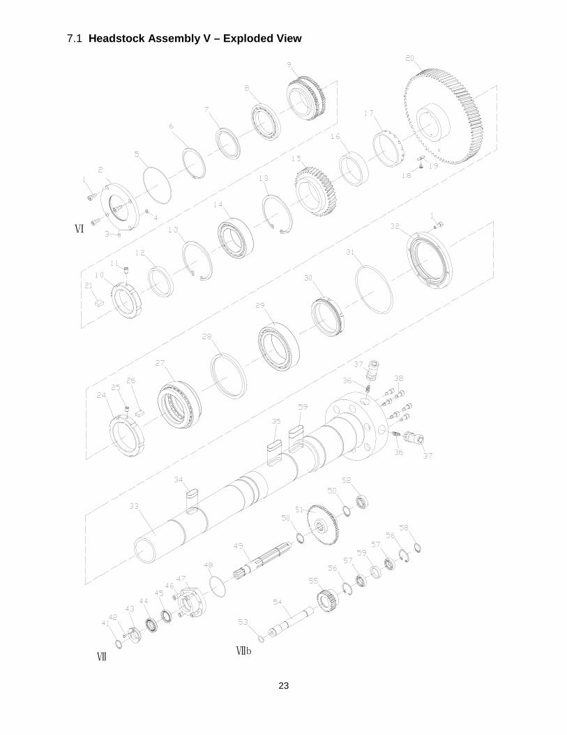
23
7.1 Headstock Assembly V – Exploded View
Ⅶ
Ⅶb
Ⅵ
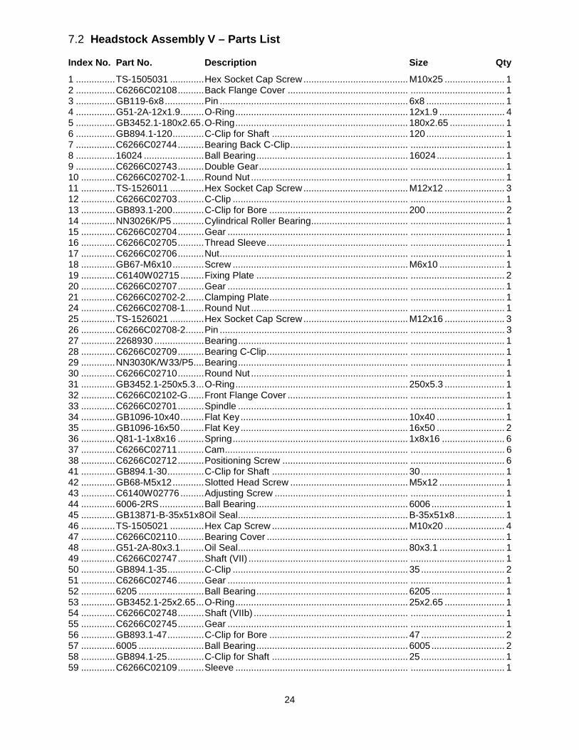
24
7.2 Headstock Assembly V – Parts List
Index No. Part No. Description Size Qty
1 ............... TS-1505031 ............. Hex Socket Cap Screw ........................................ M10x25 ....................... 1 2 ............... C6266C02108 .......... Back Flange Cover .............................................. .................................... 1 3 ............... GB119-6x8 ............... Pin ........................................................................ 6x8 .............................. 1 4 ............... G51-2A-12x1.9 ......... O-Ring .................................................................. 12x1.9 ......................... 4 5 ............... GB3452.1-180x2.65 . O-Ring .................................................................. 180x2.65 ..................... 1 6 ............... GB894.1-120 ............ C-Clip for Shaft .................................................... 120 .............................. 1 7 ............... C6266C02744 .......... Bearing Back C-Clip ............................................. .................................... 1 8 ............... 16024 ....................... Ball Bearing .......................................................... 16024 .......................... 1 9 ............... C6266C02743 .......... Double Gear ......................................................... .................................... 1 10 ............. C6266C02702-1 ....... Round Nut ............................................................ .................................... 1 11 ............. TS-1526011 ............. Hex Socket Cap Screw ........................................ M12x12 ....................... 3 12 ............. C6266C02703 .......... C-Clip ................................................................... .................................... 1 13 ............. GB893.1-200 ............ C-Clip for Bore ..................................................... 200 .............................. 2 14 ............. NN3026K/P5 ............ Cylindrical Roller Bearing ..................................... .................................... 1 15 ............. C6266C02704 .......... Gear ..................................................................... .................................... 1 16 ............. C6266C02705 .......... Thread Sleeve ...................................................... .................................... 1 17 ............. C6266C02706 .......... Nut ........................................................................ .................................... 1 18 ............. GB67-M6x10 ............ Screw ................................................................... M6x10 ......................... 1 19 ............. C6140W02715 ......... Fixing Plate .......................................................... .................................... 2 20 ............. C6266C02707 .......... Gear ..................................................................... .................................... 1 21 ............. C6266C02702-2 ....... Clamping Plate ..................................................... .................................... 1 24 ............. C6266C02708-1 ....... Round Nut ............................................................ .................................... 1 25 ............. TS-1526021 ............. Hex Socket Cap Screw ........................................ M12x16 ....................... 3 26 ............. C6266C02708-2 ....... Pin ........................................................................ .................................... 3 27 ............. 2268930 ................... Bearing ................................................................. .................................... 1 28 ............. C6266C02709 .......... Bearing C-Clip ...................................................... .................................... 1 29 ............. NN3030K/W33/P5 .... Bearing ................................................................. .................................... 1 30 ............. C6266C02710 .......... Round Nut ............................................................ .................................... 1 31 ............. GB3452.1-250x5.3 ... O-Ring .................................................................. 250x5.3 ....................... 1 32 ............. C6266C02102-G ...... Front Flange Cover .............................................. .................................... 1 33 ............. C6266C02701 .......... Spindle ................................................................. .................................... 1 34 ............. GB1096-10x40 ......... Flat Key ................................................................ 10x40 .......................... 1 35 ............. GB1096-16x50 ......... Flat Key ................................................................ 16x50 .......................... 2 36 ............. Q81-1-1x8x16 .......... Spring ................................................................... 1x8x16 ........................ 6 37 ............. C6266C02711 .......... Cam ...................................................................... .................................... 6 38 ............. C6266C02712 .......... Positioning Screw ................................................ .................................... 6 41 ............. GB894.1-30 .............. C-Clip for Shaft .................................................... 30 ................................ 1 42 ............. GB68-M5x12 ............ Slotted Head Screw ............................................. M5x12 ......................... 1 43 ............. C6140W02776 ......... Adjusting Screw ................................................... .................................... 1 44 ............. 6006-2RS ................. Ball Bearing .......................................................... 6006 ............................ 1 45 ............. GB13871-B-35x51x8 Oil Seal ................................................................. B-35x51x8 ................... 1 46 ............. TS-1505021 ............. Hex Cap Screw .................................................... M10x20 ....................... 4 47 ............. C6266C02110 .......... Bearing Cover ...................................................... .................................... 1 48 ............. G51-2A-80x3.1 ......... Oil Seal ................................................................. 80x3.1 ......................... 1 49 ............. C6266C02747 .......... Shaft (VII) ............................................................. .................................... 1 50 ............. GB894.1-35 .............. C-Clip ................................................................... 35 ................................ 2 51 ............. C6266C02746 .......... Gear ..................................................................... .................................... 1 52 ............. 6205 ......................... Ball Bearing .......................................................... 6205 ............................ 1 53 ............. GB3452.1-25x2.65 ... O-Ring .................................................................. 25x2.65 ....................... 1 54 ............. C6266C02748 .......... Shaft (VIIb) ........................................................... .................................... 1 55 ............. C6266C02745 .......... Gear ..................................................................... .................................... 1 56 ............. GB893.1-47 .............. C-Clip for Bore ..................................................... 47 ................................ 2 57 ............. 6005 ......................... Ball Bearing .......................................................... 6005 ............................ 2 58 ............. GB894.1-25 .............. C-Clip for Shaft .................................................... 25 ................................ 1 59 ............. C6266C02109 .......... Sleeve .................................................................. .................................... 1
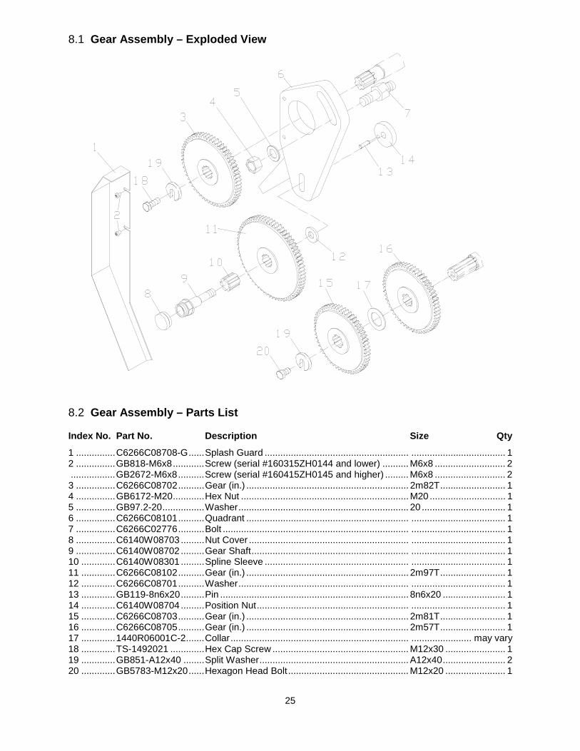
25
8.1 Gear Assembly – Exploded View
8.2 Gear Assembly – Parts List
Index No. Part No. Description Size Qty
1 ............... C6266C08708-G ...... Splash Guard ....................................................... .................................... 1 2 ............... GB818-M6x8 ............ Screw (serial #160315ZH0144 and lower) .......... M6x8 ........................... 2 ................. GB2672-M6x8 .......... Screw (serial #160415ZH0145 and higher) ......... M6x8 ........................... 2 3 ............... C6266C08702 .......... Gear (in.) .............................................................. 2m82T ......................... 1 4 ............... GB6172-M20 ............ Hex Nut ................................................................ M20 ............................. 1 5 ............... GB97.2-20 ................ Washer ................................................................. 20 ................................ 1 6 ............... C6266C08101 .......... Quadrant .............................................................. .................................... 1 7 ............... C6266C02776 .......... Bolt ....................................................................... .................................... 1 8 ............... C6140W08703 ......... Nut Cover ............................................................. .................................... 1 9 ............... C6140W08702 ......... Gear Shaft ............................................................ .................................... 1 10 ............. C6140W08301 ......... Spline Sleeve ....................................................... .................................... 1 11 ............. C6266C08102 .......... Gear (in.) .............................................................. 2m97T ......................... 1 12 ............. C6266C08701 .......... Washer ................................................................. .................................... 1 13 ............. GB119-8n6x20 ......... Pin ........................................................................ 8n6x20 ........................ 1 14 ............. C6140W08704 ......... Position Nut .......................................................... .................................... 1 15 ............. C6266C08703 .......... Gear (in.) .............................................................. 2m81T ......................... 1 16 ............. C6266C08705 .......... Gear (in.) .............................................................. 2m57T ......................... 1 17 ............. 1440R06001C-2 ....... Collar .................................................................... ....................... may vary 18 ............. TS-1492021 ............. Hex Cap Screw .................................................... M12x30 ....................... 1 19 ............. GB851-A12x40 ........ Split Washer ......................................................... A12x40 ........................ 2 20 ............. GB5783-M12x20 ...... Hexagon Head Bolt .............................................. M12x20 ....................... 1
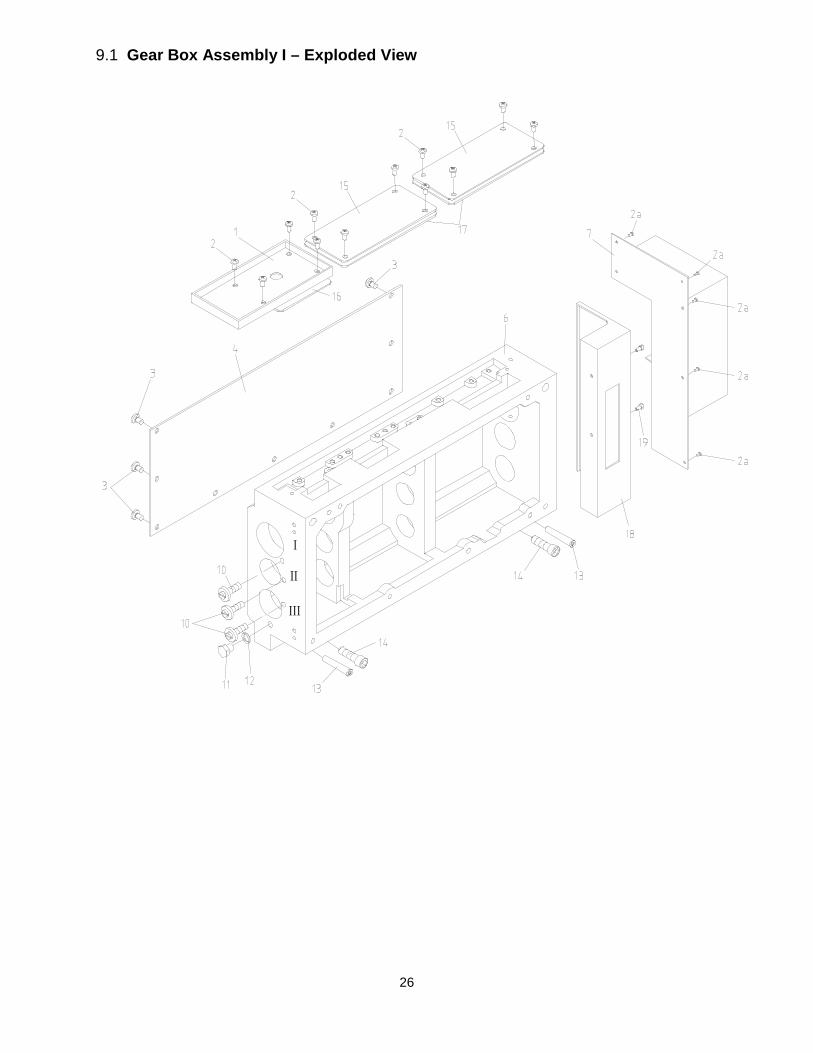
26
9.1 Gear Box Assembly I – Exploded View
Ⅱ
Ⅲ
Ⅰ
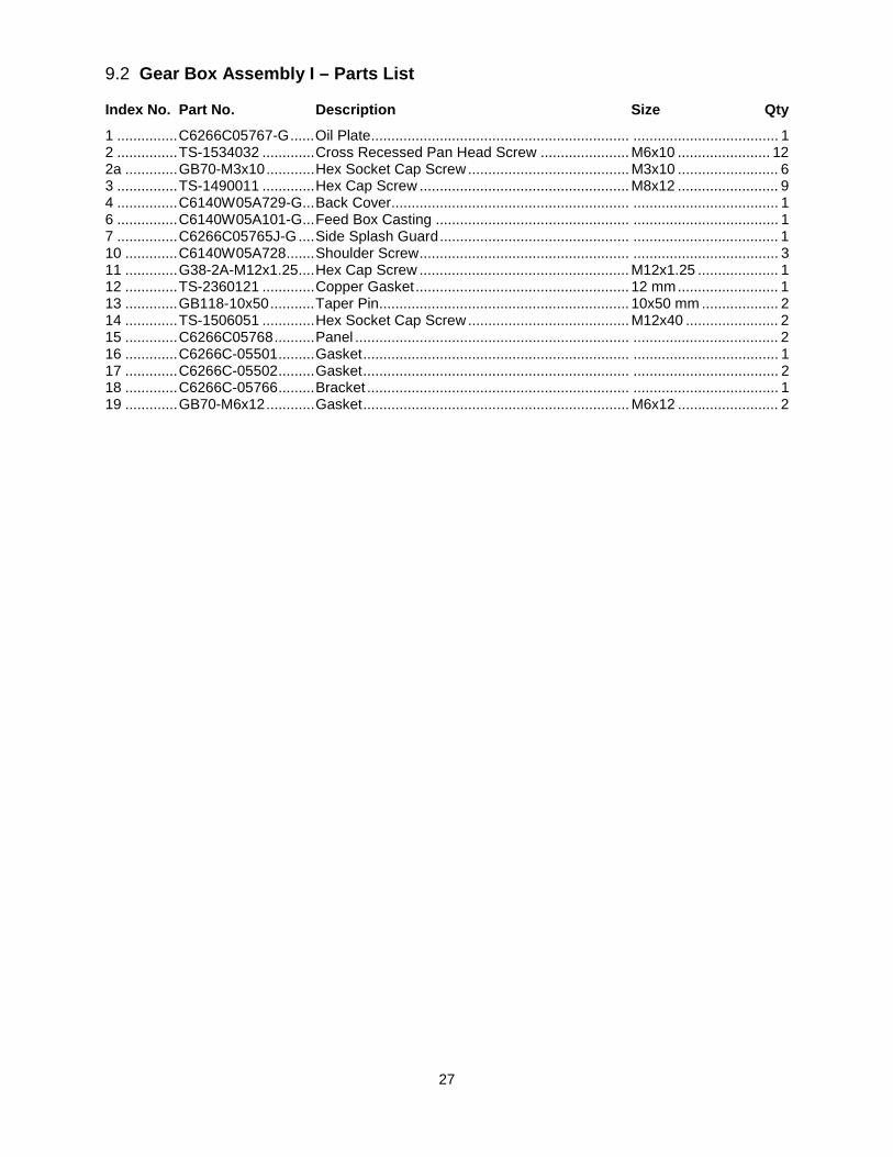
27
9.2 Gear Box Assembly I – Parts List
Index No. Part No. Description Size Qty
1 ............... C6266C05767-G ...... Oil Plate ................................................................ .................................... 1 2 ............... TS-1534032 ............. Cross Recessed Pan Head Screw ...................... M6x10 ....................... 12 2a ............. GB70-M3x10 ............ Hex Socket Cap Screw ........................................ M3x10 ......................... 6 3 ............... TS-1490011 ............. Hex Cap Screw .................................................... M8x12 ......................... 9 4 ............... C6140W05A729-G ... Back Cover........................................................... .................................... 1 6 ............... C6140W05A101-G ... Feed Box Casting ................................................ .................................... 1 7 ............... C6266C05765J-G .... Side Splash Guard ............................................... .................................... 1 10 ............. C6140W05A728 ....... Shoulder Screw .................................................... .................................... 3 11 ............. G38-2A-M12x1.25 .... Hex Cap Screw .................................................... M12x1.25 .................... 1 12 ............. TS-2360121 ............. Copper Gasket ..................................................... 12 mm ......................... 1 13 ............. GB118-10x50 ........... Taper Pin .............................................................. 10x50 mm ................... 2 14 ............. TS-1506051 ............. Hex Socket Cap Screw ........................................ M12x40 ....................... 2 15 ............. C6266C05768 .......... Panel .................................................................... .................................... 2 16 ............. C6266C-05501 ......... Gasket .................................................................. .................................... 1 17 ............. C6266C-05502 ......... Gasket .................................................................. .................................... 2 18 ............. C6266C-05766 ......... Bracket ................................................................. .................................... 1 19 ............. GB70-M6x12 ............ Gasket .................................................................. M6x12 ......................... 2
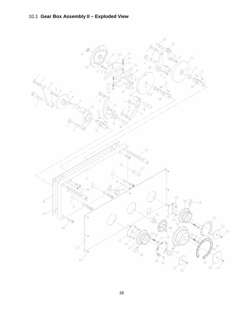
28
10.1 Gear Box Assembly II – Exploded View
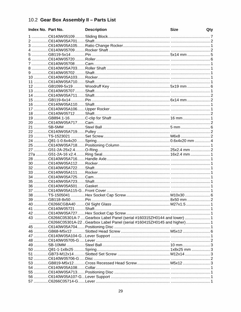
29
10.2 Gear Box Assembly II – Parts List
Index No. Part No. Description Size Qty
1 ............... C6140W05109 ......... Sliding Block......................................................... .................................... 7 2 ............... C6140W05A701 ....... Shaft ..................................................................... .................................... 2 3 ............... C6140W05A105 ....... Ratio Change Rocker ........................................... .................................... 1 4 ............... C6140W05709 ......... Rocker Shaft ........................................................ .................................... 2 5 ............... GB119-5x14 ............. Pin ........................................................................ 5x14 mm ..................... 5 6 ............... C6140W05720 ......... Roller .................................................................... .................................... 6 7 ............... C6140W05708 ......... Cam ...................................................................... .................................... 1 8 ............... C6140W05A703 ....... Roller Shaft .......................................................... .................................... 1 9 ............... C6140W05702 ......... Shaft ..................................................................... .................................... 1 10 ............. C6140W05A103 ....... Rocker .................................................................. .................................... 1 11 ............. C6140W05A710 ....... Shaft ..................................................................... .................................... 1 12 ............. GB1099-5x19 ........... Woodruff Key ....................................................... 5x19 mm ..................... 6 13 ............. C6140W05707 ......... Shaft ..................................................................... .................................... 1 14 ............. C6140W05A711 ....... Shaft ..................................................................... .................................... 2 15 ............. GB119-6x14 ............. Pin ........................................................................ 6x14 mm ..................... 2 16 ............. C6140W05A110 ....... Shaft ..................................................................... .................................... 1 17 ............. C6140W05A106 ....... Upper Rocker ....................................................... .................................... 1 18 ............. C6140W05712 ......... Shaft ..................................................................... .................................... 2 19 ............. GB894.1-16 .............. C-clip for Shaft ..................................................... 16 mm ......................... 1 20 ............. C6140W05A717 ....... Cam ...................................................................... .................................... 2 21 ............. SB-5MM ................... Steel Ball .............................................................. 5 mm ........................... 6 22 ............. C6140W05A719 ....... Pulley ................................................................... .................................... 2 23 ............. TS-1523021 ............. Set Screw ............................................................. M6x8 ........................... 2 24 ............. Q81-1-0.6x4x20 ....... Spring ................................................................... 0.6x4x20 mm .............. 4 25 ............. C6140W05A718 ....... Positioning Column .............................................. .................................... 1 27 ............. G51-2A-25x2.4 ......... O-Ring .................................................................. 25x2.4 mm .................. 2 27a ........... G51-2A-16 x2.4 ........ Ring Seal .............................................................. 16x2.4 mm .................. 1 28 ............. C6140W05A716 ....... Handle Axle .......................................................... .................................... 1 30 ............. C6140W05A112 ....... Rocker .................................................................. .................................... 1 32 ............. C6140W05A722 ....... Shaft ..................................................................... .................................... 1 33 ............. C6140W05A111 ....... Rocker .................................................................. .................................... 1 34 ............. C6140W05A725 ....... Cam ...................................................................... .................................... 1 35 ............. C6140W05A723 ....... Shaft ..................................................................... .................................... 1 36 ............. C6140W05A501 ....... Gasket .................................................................. .................................... 1 37 ............. C6140W05A115-G ... Front Cover .......................................................... .................................... 1 38 ............. TS-1505041 ............. Hex Socket Cap Screw ........................................ M10x30 ....................... 6 39 ............. GB118-8x50 ............. Pin ........................................................................ 8x50 mm ..................... 2 40 ............. C6266CGBA40 ........ Oil Sight Glass ..................................................... M27x1.5 ...................... 1 41 ............. C6140W05721 ......... Shaft ..................................................................... .................................... 1 42 ............. C6140W05A727 ....... Hex Socket Cap Screw ........................................ .................................... 1 43 ............ C6266C05301A-7 .... Gearbox Label Panel (serial #160315ZH0144 and lower) ....................... 1 ................. C6266C05301A-22 .. Gearbox Label Panel (serial #160415ZH0145 and higher) ...................... 1 45 ............. C6140W05A704 ....... Positioning Disc ................................................... .................................... 1 46 ............. GB68-M5x12 ............ Slotted Head Screw ............................................. M5x12 ......................... 6 47 ............. C6140W05A104-G ... Lever Support ...................................................... .................................... 1 48 ............. C6140W05705-G ..... Lever .................................................................... .................................... 2 49 ............. SB-10MM ................. Steel Ball .............................................................. 10 mm ......................... 3 50 ............. Q81-1-1x8x25 .......... Spring ................................................................... 1x8x25 mm ................. 3 51 ............. GB73-M12x14 .......... Slotted Set Screw ................................................ M12x14 ....................... 3 52 ............. C6140W05706-G ..... Disc ...................................................................... .................................... 2 53 ............. GB819-M5x12 .......... Cross Recessed Head Screw .............................. M5x12 ......................... 3 54 ............. C6140W05A108 ....... Collar .................................................................... .................................... 1 55 ............. C6140W05A713 ....... Positioning Disc ................................................... .................................... 1 56 ............. C6140W05A107-G ... Lever Support ...................................................... .................................... 1 57 ............. C6266C05714-G ...... Lever .................................................................... .................................... 1

30
Index No. Part No. Description Size Qty
58 ............. C6140W05715-G ..... Cover .................................................................... .................................... 1 59 ............. C6140W05A724 ....... Positioning Disc ................................................... .................................... 1 60 ............. C6140W05A104-G ... Lever Support ...................................................... .................................... 1 61 ............ C6140W05308 ......... Handle Panel (serial #160315ZH0144 and lower) .................................... 1 ................. C6140W05308-2 ...... Handle Panel (serial #160415ZH0145 and higher) .................................. 1 62 ............ C6140W05A307 ....... Handle Panel (serial #160315ZH0144 and lower) .................................... 1 ................. C6140W05A307-2 ... Handle Panel (serial #160415ZH0145 and higher) .................................. 1 63 ............ C6140W05306 ......... Handle Panel (serial #160315ZH0144 and lower) .................................... 1 ................. C6140W05306-2 ...... Handle Panel (serial #160415ZH0145 and higher) .................................. 1 64 ............ TS-1531012 ............. Cross Recessed Pan Head Screw (serial #160315ZH0144 and lower) ..... ................. ................................. ............................................................................. M3x6 ......................... 17 ................. GB2672- M3x6 ......... Screw (serial #160415ZH0145 and higher) ......... M3x6 ......................... 17
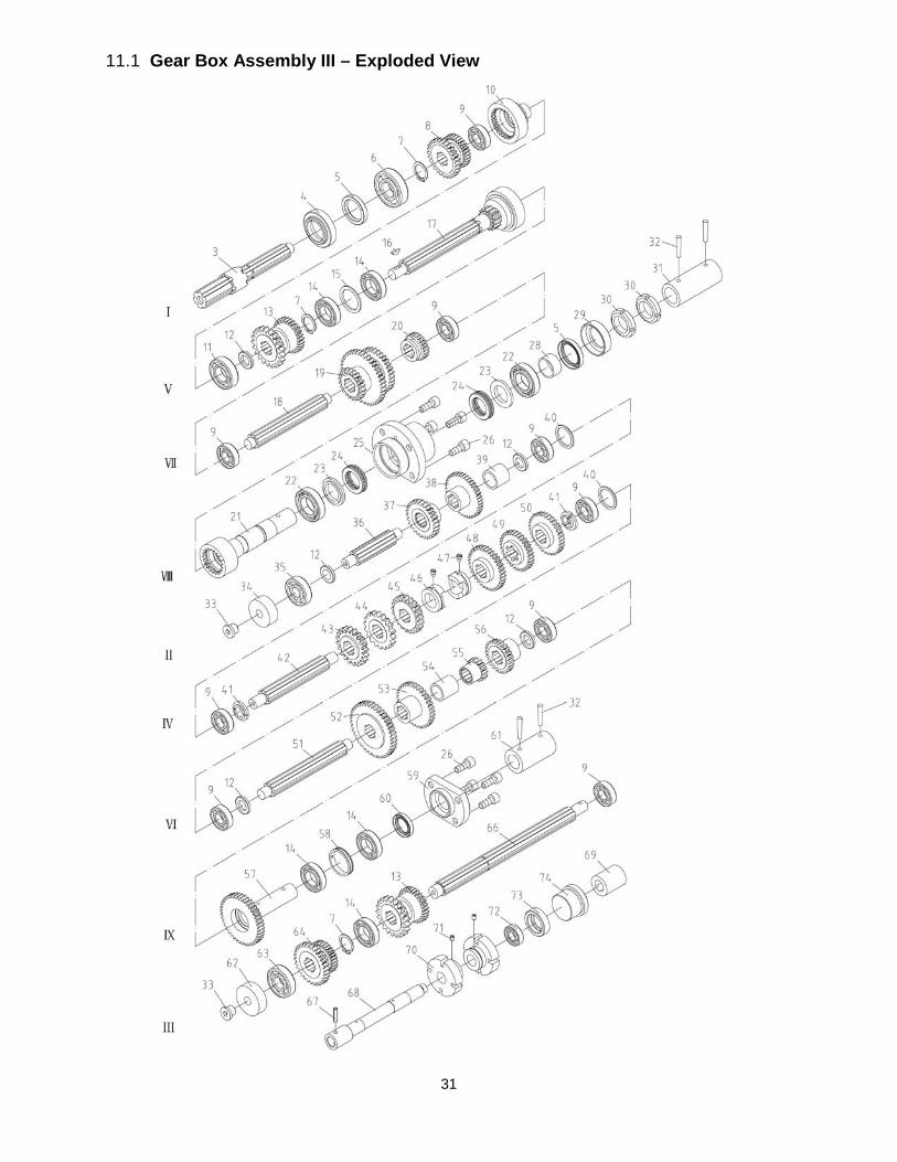
31
11.1 Gear Box Assembly III – Exploded View
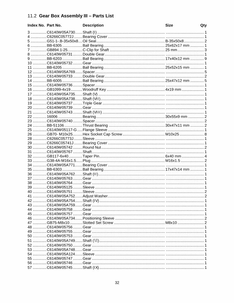
32
11.2 Gear Box Assembly III – Parts List
Index No. Part No. Description Size Qty
3 ............... C6140W05A730 ....... Shaft (I) ................................................................ .................................... 1 4 ............... C6266C05772J ........ Bearing Cover ...................................................... .................................... 1 5 ............... G51-1-.B-35x50x8 .... Oil Seal ................................................................. B-35x50x8 ................... 2 6 ............... BB-6305 ................... Ball Bearing .......................................................... 25x62x17 mm ............. 1 7 ............... GB894.1-25 .............. C-Clip for Shaft .................................................... 25 mm ......................... 3 8 ............... C6140W05731 ......... Double Gear ......................................................... .................................... 1 9 ............... BB-6203 ................... Ball Bearing .......................................................... 17x40x12 mm ............. 9 10 ............. C6140W05732 ......... Gear ..................................................................... .................................... 1 11 ............. BB-6205 ................... Ball Bearing .......................................................... 25x52x15 mm ............. 1 12 ............. C6140W05A769 ....... Spacer .................................................................. .................................... 5 13 ............. C6140W05733 ......... Double Gear ......................................................... .................................... 2 14 ............. BB-6005 ................... Ball Bearing .......................................................... 25x47x12 mm ............. 5 15 ............. C6140W05736 ......... Spacer .................................................................. .................................... 1 16 ............. GB1099-4x19 ........... Woodruff Key ....................................................... 4x19 mm ..................... 1 17 ............. C6140W05A735 ....... Shaft (V) ............................................................... .................................... 1 18 ............. C6140W05A738 ....... Shaft (VII)............................................................. .................................... 1 19 ............. C6140W05737 ......... Triple Gear ........................................................... .................................... 1 20 ............. C6140W05739 ......... Gear ..................................................................... .................................... 1 21 ............. C6140W05743 ......... Shaft (VIII) ........................................................... .................................... 1 22 ............. 16006 ....................... Bearing ................................................................. 30x55x9 mm ............... 2 23 ............. C6140W05740 ......... Spacer .................................................................. .................................... 2 24 ............. BB-51106 ................. Thrust Bearing ..................................................... 30x47x11 mm ............. 2 25 ............. C6140W05117-G ..... Flange Sleeve ...................................................... .................................... 1 26 ............. GB70- M10x25 ......... Hex Socket Cap Screw ........................................ M10x25 ....................... 8 28 ............. C6266C05773J ........ Sleeve .................................................................. .................................... 1 29 ............. C6266C05741J ........ Bearing Cover ...................................................... .................................... 1 30 ............. C6140W05742 ......... Round Nut ............................................................ .................................... 2 31 ............. C6140W05767 ......... Shaft ..................................................................... .................................... 1 32 ............. GB117-6x40 ............. Taper Pin .............................................................. 6x40 mm ..................... 4 33 ............. G38-4A-M16x1.5 ...... Plug ...................................................................... M16x1.5 ...................... 2 34 ............. C6140W05A771 ....... Bearing Cover ...................................................... .................................... 1 35 ............. BB-6303 ................... Ball Bearing .......................................................... 17x47x14 mm ............. 1 36 ............. C6140W05A762 ....... Shaft (II) ............................................................... .................................... 1 37 ............. C6140W05763 ......... Gear ..................................................................... .................................... 1 38 ............. C6140W05764 ......... Gear ..................................................................... .................................... 1 39 ............. C6140W05125 ......... Sleeve .................................................................. .................................... 1 40 ............. C6140W05751 ......... Sleeve .................................................................. .................................... 2 41 ............. C6140W05A752 ....... Adjust Washer ...................................................... .................................... 2 42 ............. C6140W05A754 ....... Shaft (IV) .............................................................. .................................... 1 43 ............. C6140W05A759 ....... Gear ..................................................................... .................................... 1 44 ............. C6140W05758 ......... Gear ..................................................................... .................................... 1 45 ............. C6140W05757 ......... Gear ..................................................................... .................................... 1 46 ............. C6140W05A734 ....... Positioning Sleeve ............................................... .................................... 2 47 ............. GB75-M8x10 ............ Slotted Set Screw ................................................ M8x10 ......................... 2 48 ............. C6140W05756 ......... Gear ..................................................................... .................................... 1 49 ............. C6140W05755 ......... Gear ..................................................................... .................................... 1 50 ............. C6140W05753 ......... Gear ..................................................................... .................................... 1 51 ............. C6140W05A749 ....... Shaft (Ⅵ) .............................................................. .................................... 1 52 ............. C6140W05750 ......... Gear ..................................................................... .................................... 1 53 ............. C6140W05A748 ....... Gear ..................................................................... .................................... 1 54 ............. C6140W05A124 ....... Sleeve .................................................................. .................................... 1 55 ............. C6140W05747 ......... Gear ..................................................................... .................................... 1 56 ............. C6140W05746 ......... Gear ..................................................................... .................................... 1 57 ............. C6140W05745 ......... Shaft (IX) .............................................................. .................................... 1
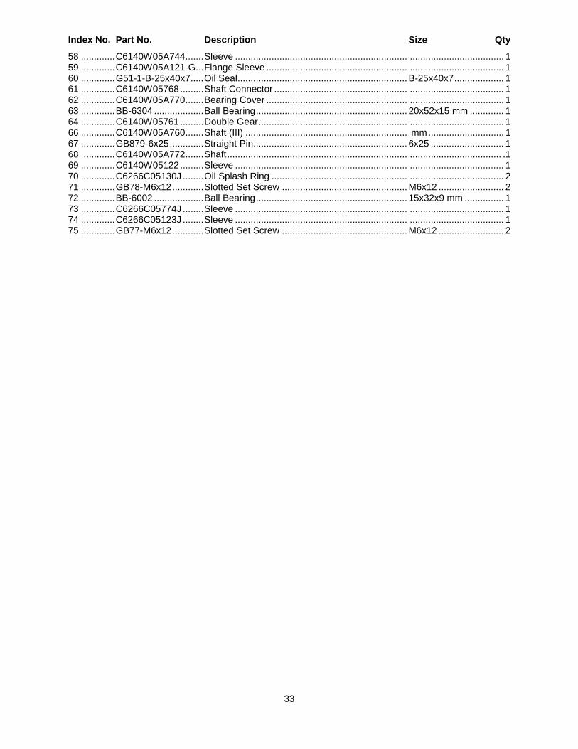
33
Index No. Part No. Description Size Qty
58 ............. C6140W05A744 ....... Sleeve .................................................................. .................................... 1 59 ............. C6140W05A121-G ... Flange Sleeve ...................................................... .................................... 1 60 ............. G51-1-B-25x40x7 ..... Oil Seal ................................................................. B-25x40x7 ................... 1 61 ............. C6140W05768 ......... Shaft Connector ................................................... .................................... 1 62 ............. C6140W05A770 ....... Bearing Cover ...................................................... .................................... 1 63 ............. BB-6304 ................... Ball Bearing .......................................................... 20x52x15 mm ............. 1 64 ............. C6140W05761 ......... Double Gear ......................................................... .................................... 1 66 ............. C6140W05A760 ....... Shaft (III) .............................................................. mm ............................. 1 67 ............. GB879-6x25 ............. Straight Pin........................................................... 6x25 ............................ 1 68 ............ C6140W05A772 ....... Shaft ..................................................................... ................................... .1 69 ............. C6140W05122 ......... Sleeve .................................................................. .................................... 1 70 ............. C6266C05130J ........ Oil Splash Ring .................................................... .................................... 2 71 ............. GB78-M6x12 ............ Slotted Set Screw ................................................ M6x12 ......................... 2 72 ............. BB-6002 ................... Ball Bearing .......................................................... 15x32x9 mm ............... 1 73 ............. C6266C05774J ........ Sleeve .................................................................. .................................... 1 74 ............. C6266C05123J ........ Sleeve .................................................................. .................................... 1 75 ............. GB77-M6x12 ............ Slotted Set Screw ................................................ M6x12 ......................... 2
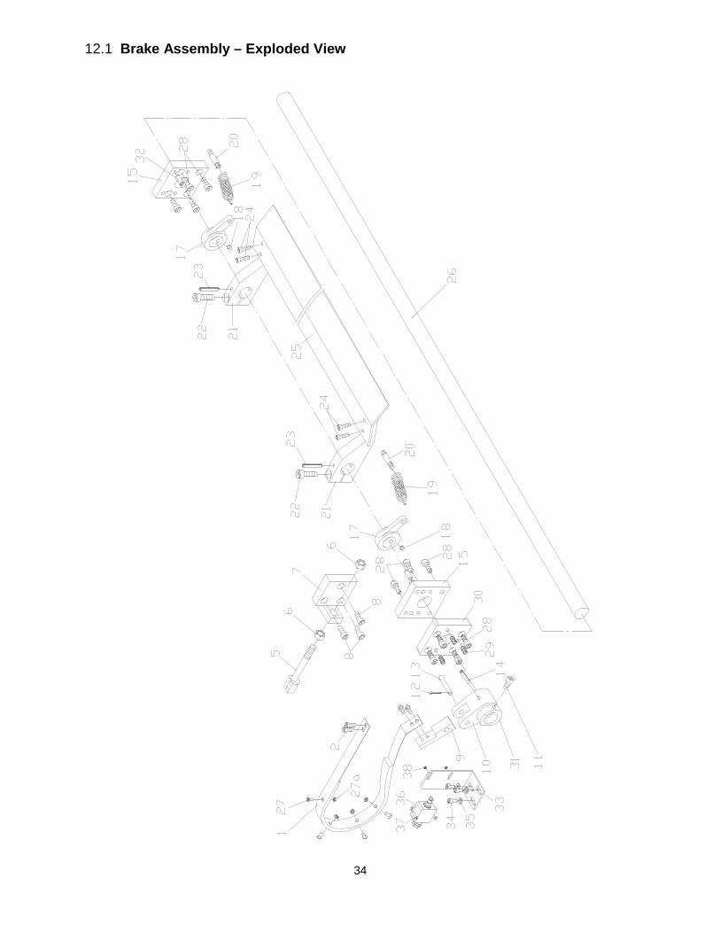
34
12.1 Brake Assembly – Exploded View
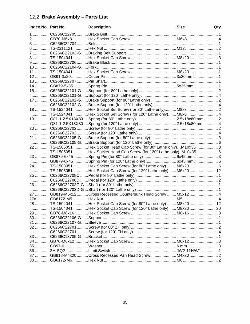
35
12.2 Brake Assembly – Parts List
Index No. Part No. Description Size Qty
1 ............... C6266C22705 .......... Brake Belt ............................................................. .................................... 1 2 ............... GB70-M6x8 .............. Hex Socket Cap Screw ........................................ M6x8 ........................... 4 5 ............... C6266C22704 .......... Bolt ....................................................................... .................................... 1 6 ............... TS-2311121 ............. Hex Nut ................................................................ M12 ............................. 2 7 ............... C6266C22103-G ...... Braking Belt Support ............................................ .................................... 1 8 ............... TS-1504041 ............. Hex Socket Cap Screw ........................................ M8x20 ......................... 3 9 ............... C6266C22706 .......... Brake Block .......................................................... .................................... 1 10 ............. C6266C22104-G ...... Fork ...................................................................... .................................... 1 11 ............. TS-1504041 ............. Hex Socket Cap Screw ........................................ M8x20 ......................... 1 12 ............. GB91-3x20 ............... Cotter Pin ............................................................. 3x20 mm ..................... 1 13 ............. C6266C22707 .......... Pin Shaft ............................................................... .................................... 1 14 ............. GB879-5x35 ............. Spring Pin............................................................. 5x35 mm ..................... 1 15 ............. C6266C22101-G ...... Support (for 80” Lathe only) ................................. .................................... 2 ................. C6266C22101-G ...... Support (for 120” Lathe only) ............................... .................................... 4 17 ............. C6266C22102-G ...... Brake Support (for 80” Lathe only) ...................... .................................... 2 ................. C6266C22102-G ...... Brake Support (for 120” Lathe only) .................... .................................... 4 18 ............. TS-1524041 ............. Hex Socket Set Screw (for 80” Lathe only) .......... M8x8 ........................... 2 ................. TS-1524041 ............. Hex Socket Set Screw ( for 120” Lathe only) ....... M8x8 ........................... 4 19 ............. Q81-1-2.5X18X80 .... Spring (for 80” Lathe only) ................................... 2.5x18x80 mm ............ 2 ................. Q81-1-2.5X18X80 .... Spring (for 120” Lathe only) ................................. 2.5x18x80 mm ............ 4 20 ............. C6266C22702 .......... Screw (for 80” Lathe only) .................................... .................................... 2 ................. C6266C22702 .......... Screw (for 120” Lathe only) .................................. .................................... 4 21 ............. C6266C22105-G ...... Brake Support (for 80” Lathe only) ...................... .................................... 3 ................. C6266C22105-G ...... Brake Support (for 120” Lathe only) .................... .................................... 6 22 ............. TS-1505051 ............. Hex Socket Head Cap Screw (for 80” Lathe only)…M10x35 ................... 3 ................. TS-1505051 ............. Hex Socket Head Cap Screw (for 120” Lathe only)..M10x35 ................... 6 23 ............. GB879-6x45 ............. Spring Pin (for 80” Lathe only) ............................. 6x45 mm ..................... 3 ................. GB879-6x45 ............. Spring Pin (for 120” Lathe only) ........................... 6x45 mm ..................... 6 24 ............. TS-1503051 ............. Hex Socket Cap Screw (for 80” Lathe only) ........ M6x20 ......................... 6 ................. TS-1503051 ............. Hex Socket Cap Screw (for 120” Lathe only) ...... M6x20 ....................... 12 25 ............. C6266C22708C ....... Pedal (for 80” Lathe only) .................................... .................................... 1 ................. C6266C22708D ....... Pedal (for 120” Lathe only) .................................. .................................... 2 26 ............. C6266C22703C-G ... Shaft (for 80” Lathe only) ..................................... .................................... 1 ................. C6266C22703D-G ... Shaft (for 120” Lathe only) ................................... .................................... 1 27 ............. GB819-M5x12 .......... Cross Recessed Countersunk Head Screw ........ M5x12 ......................... 4 27a ........... GB6172-M5 .............. Hex Nut ................................................................ M5 ............................... 4 28 ............. TS-1504041 ............. Hex Socket Cap Screw (for 80” Lathe only) ........ M8x20 ....................... 12 ................. TS-1504041 ............. Hex Socket Cap Screw (for 120” Lathe only) ...... M8x20 ....................... 20 29 ............. GB78-M8x16 ............ Hex Socket Cap Screw ........................................ M8x16 ......................... 3 30 ............. C6266C22106-G ...... Support ................................................................. .................................... 1 31 ............. C6266C22107-G ...... Sleeve .................................................................. .................................... 1 32 ............. C6266C22701 .......... Screw (for 80” ZH only) ........................................ .................................... 2 ................. C6266C22701 .......... Screw (for 120” ZH only) ...................................... .................................... 4 33 ............. C6266C18705-G ...... Bracket ................................................................. .................................... 1 34 ............. GB70-M6x12 ............ Hex Socket Cap Screw ........................................ M6x12 ......................... 3 35 ............. GB97-6 ..................... Washer ................................................................. 6 mm ........................... 3 36 ............. ZH-SQ2 .................... Limit Switch .......................................................... JW2-11H/W1 .............. 1 37 ............. GB818-M4x20 .......... Cross Recessed Pan Head Screw ...................... M4x20 ......................... 2 38 ............. GB6172-M6 .............. Hex Nut ................................................................ M6 ............................... 2
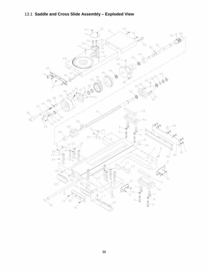
36
13.1 Saddle and Cross Slide Assembly – Exploded View
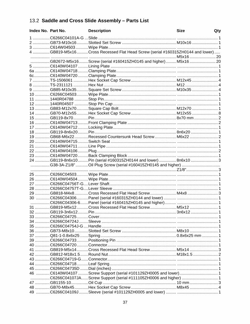
37
13.2 Saddle and Cross Slide Assembly – Parts List
Index No. Part No. Description Size Qty
1 ............... C6266C04101A-G ... Slide ..................................................................... .................................... 1 2 ............... GB73-M10x16 .......... Slotted Set Screw ................................................ M10x16 ....................... 1 3 ............... C614W04503 ........... Wipe Plate ............................................................ .................................... 1 4 ............... GB819-M5x16 .......... Cross Recessed Flat Head Screw (serial #160315ZH0144 and lower) ..... ................. ................................. ............................................................................. M5x16 ....................... 20 ................. GB2672-M5x16 ........ Screw (serial #160415ZH0145 and higher) ......... M5x16 ....................... 20 5 ............... C6140W04107 ......... Lining Plate .......................................................... .................................... 1 6a ............. C6140W04718 ......... Clamping Plate ..................................................... .................................... 1 6c .............. C6140W04720 ......... Clamping Plate ..................................................... .................................... 1 7 ............... TS-1506061 ............. Hex Socket Cap Screw ........................................ M12x45 ....................... 4 8 ............... TS-2311121 ............. Hex Nut ................................................................ M12 ............................. 4 9 ............... GB85-M10x35 .......... Square Set Screw ................................................ M10x35 ....................... 4 10 ............. C6266C04503 .......... Wipe Plate ............................................................ .................................... 1 11 ............. 1440R04788 ............ Stop Pin ................................................................ .................................... 1 12 ............. 1440R04507 ............ Stop Pin Cap ........................................................ .................................... 1 13 ............. GB83-M12x70 .......... Square Cap Bolt ................................................... M12x70 ....................... 1 14 ............. GB70-M12x55 .......... Hex Socket Cap Screw ........................................ M12x55 ....................... 8 15 ............. GB119-8x70 ............. Pin ........................................................................ 8x70 mm ..................... 2 16 ............. C6140W04713 ......... Front Clamping Plate ........................................... .................................... 2 17 ............. C6140W04712 ......... Locking Plate........................................................ .................................... 1 18 ............. GB119-8n6x20 ......... Pin ........................................................................ 8n6x20 ........................ 1 19 ............. GB68-M6x22 ............ Recessed Countersunk Head Screw ................... M6x22 ......................... 2 20 ............. C6140W04715 ......... Switch Seat .......................................................... .................................... 1 21 ............. C6140W04711 ......... Line Pipe .............................................................. .................................... 1 22 ............. C6140W04106 ......... Plug ...................................................................... .................................... 2 23 ............. C6140W04720 ......... Back Clamping Block ........................................... .................................... 1 24 ............. GB119-8n6x10 ......... Pin (serial #160315ZH0144 and lower) ............... 8n6x10 ........................ 3 ................. G38-3A-Z1/8” ........... Oil Plug Screw (serial #160415ZH0145 and higher) .................................. ................. ................................. ............................................................................. Z1/8”............................ 3 25 ............. C6266C04503 .......... Wipe Plate ............................................................ .................................... 1 26 ............. C6140W04504 ......... Wipe Plate ............................................................ .................................... 1 27 ............. C6266C04756T-G .... Lever Shaft ........................................................... .................................... 1 28 ............. C6266C04757T-G .... Lever Sleeve ........................................................ .................................... 1 29 ............. GB818-M4x8 ............ Cross Recessed Flat Head Screw ....................... M4x8 ........................... 3 30 ............ C6266C04306 .......... Panel (serial #160315ZH0144 and lower) ........... .................................... 1 ................. C6266C04306-6 ....... Panel (serial #160415ZH0145 and higher) .......... .................................... 1 31 ............. GB819-M5x12 .......... Cross Recessed Flat Head Screw ....................... M5x12 ......................... 1 32 ............. GB119-3n6x12 ......... Pin ........................................................................ 3n6x12 ........................ 1 33 ............. C6266C04725 .......... Cover .................................................................... .................................... 1 34 ............. C6266C04724J ........ Sleeve .................................................................. .................................... 1 35 ............. C6266C04754J-G .... Handle .................................................................. .................................... 1 36 ............. GB73-M8x10 ............ Slotted Set Screw ................................................ M8x10 ......................... 1 37 ............. Q81-1-0.8x6x25 ....... Spring ................................................................... 0.8x6x25 mm .............. 1 39 ............. C6266C04733 .......... Positioning Pin ..................................................... .................................... 1 40 ............. C6266C04720 .......... Connector............................................................. .................................... 1 41 ............. GB819-M5x14 .......... Cross Recessed Flat Head Screw ....................... M5x14 ......................... 3 42 ............. GB812-M18x1.5 ....... Round Nut ............................................................ M18x1.5 ...................... 2 43 ............. C6266C04719-G ...... Connector............................................................. .................................... 1 44 ............. C6266C04718 .......... Leaf Spring ........................................................... .................................... 1 45 ............. C6266C04735D ....... Dial (inches) ......................................................... .................................... 1 46 ............ C6140W04107 ......... Screw Support (serial #101129ZH0005 and lower) .................................. 1 ................. C6266C04107JA ...... Screw Support (serial #111105ZH0006 and higher) ................................ 1 47 ............. GB1155-10 ............... Oil Cup ................................................................. 10 mm ......................... 3 48 ............. GB70-M8x45 ............ Hex Socket Cap Screw ........................................ M8x45 ......................... 4 49 ............ C6266C04109J ........ Sleeve (serial #101129ZH0005 and lower) ......... .................................... 1
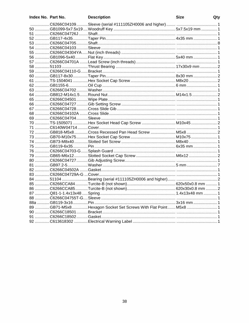
38
Index No. Part No. Description Size Qty
................. C6266C04109 .......... Sleeve (serial #111105ZH0006 and higher) ........ .................................... 1 50 ............. GB1099-5x7.5x19 .... Woodruff Key ....................................................... 5x7.5x19 mm .............. 1 51 ............. C6266C04726J ........ Shaft ..................................................................... .................................... 1 52 ............. GB117-4x35 ............. Taper Pin .............................................................. 4x35 mm ..................... 1 53 ............. C6266C04705 .......... Shaft ..................................................................... .................................... 8 54 ............. C6266C04103 .......... Sleeve .................................................................. .................................... 1 55 ............. C6266C04304YA ..... Nut (inch threads) ................................................ .................................... 1 56 ............. GB1096-5x40 ........... Flat Key ................................................................ 5x40 mm ..................... 1 57 ............. C6266C04701A ....... Lead Screw (inch threads) ................................... .................................... 1 58 ............. 51103 ....................... Thrust Bearing ..................................................... 17x30x9 mm ............... 2 59 ............. C6266C04110-G ...... Bracket ................................................................. .................................... 1 60 ............. GB117-8x30 ............. Taper Pin .............................................................. 8x30 mm ..................... 2 61 ............. TS-1504041 ............. Hex Socket Cap Screw ........................................ M8x20 ......................... 2 62 ............. GB1155-6 ................. Oil Cup ................................................................. 6 mm ........................... 1 63 ............. C6266C04702 .......... Washer ................................................................. .................................... 1 64 ............. GB812-M14x1.5 ....... Round Nut ............................................................ M14x1.5 ...................... 2 65 ............. C6266C04501 .......... Wipe Plate ............................................................ .................................... 1 66 ............. C6266C04727 .......... Gib Setting Screw ................................................ .................................... 1 67 ............. C6266C04728 .......... Cross Slide Gib .................................................... .................................... 1 68 ............. C6266C04102A ....... Cross Slide ........................................................... .................................... 1 69 ............. C6266C04704 .......... Sleeve .................................................................. .................................... 1 70 ............. TS-1505071 ............. Hex Socket Head Cap Screw .............................. M10x45 ....................... 2 71 ............. C6140W04714 ......... Cover .................................................................... .................................... 1 72 ............. GB818-M5x8 ............ Cross Recessed Pan Head Screw ...................... M5x8 ........................... 2 73 ............. GB70-M10x75 .......... Hex Socket Cap Screw ........................................ M10x75 ....................... 1 74 ............. GB73-M8x40 ............ Slotted Set Screw ................................................ M8x40 ......................... 1 75 ............. GB119-6x35 ............. Pin ........................................................................ 6x35 mm ..................... 1 76 ............. C6266C04703-G ...... Splash Guard ....................................................... .................................... 1 79 ............. GB65-M6x12 ............ Slotted Socket Cap Screw ................................... M6x12 ......................... 2 80 ............. C6266C04727 .......... Gib Adjusting Screw ............................................. .................................... 1 81 ............. GB97.2-5 .................. Washer ................................................................. 5 mm ........................... 7 82 ............. C6266C04502A ....... Gasket .................................................................. .................................... 1 83 ............. C6266C04729A-G ... Cover .................................................................... .................................... 1 84 ............. 51104 ....................... Bearing (serial #111105ZH0006 and higher) ....... .................................... 2 85 ............. C6266CCA84 ........... Turcite-B (not shown) ........................................... 620x50x0.8 mm .......... 1 86 ............. C6266CCA85 ........... Turcite-B (not shown) ........................................... 620x30x0.8 mm .......... 2 87 ............. Q81-1-1.4x13x48 ..... Spring ................................................................... 1.4x13x48 mm ............ 1 88 ............. C6266C04755T-G .... Sleeve .................................................................. .................................... 1 88a ........... GB119-3x16 ............. Pin ........................................................................ 3x16 mm ..................... 1 89 ............. GB71-M5x8 .............. Hexagon Socket Set Screws With Flat Point ....... M5x8 ........................... 1 90 ............. C6266C18501 .......... Bracket ................................................................. .................................... 1 91 ............. C6266C18502 .......... Gasket .................................................................. .................................... 1 92 ............. C613618302 ............ Electrical Warning Label ...................................... .................................... 1
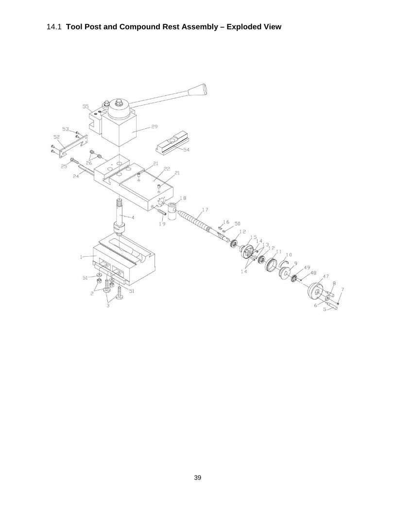
39
14.1 Tool Post and Compound Rest Assembly – Exploded View
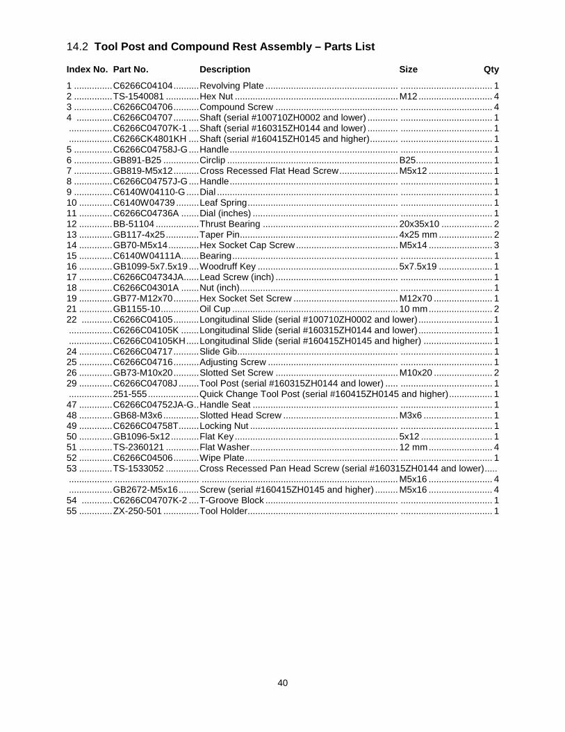
40
14.2 Tool Post and Compound Rest Assembly – Parts List
Index No. Part No. Description Size Qty
1 ............... C6266C04104 .......... Revolving Plate .................................................... .................................... 1 2 ............... TS-1540081 ............. Hex Nut ................................................................ M12 ............................. 4 3 ............... C6266C04706 .......... Compound Screw ................................................ .................................... 4 4 .............. C6266C04707 .......... Shaft (serial #100710ZH0002 and lower) ............ .................................... 1 ................. C6266C04707K-1 .... Shaft (serial #160315ZH0144 and lower) ............ .................................... 1 ................. C6266CK4801KH .... Shaft (serial #160415ZH0145 and higher) ........... .................................... 1 5 ............... C6266C04758J-G .... Handle .................................................................. .................................... 1 6 ............... GB891-B25 .............. Circlip ................................................................... B25 .............................. 1 7 ............... GB819-M5x12 .......... Cross Recessed Flat Head Screw ....................... M5x12 ......................... 1 8 ............... C6266C04757J-G .... Handle .................................................................. .................................... 1 9 ............... C6140W04110-G ..... Dial ....................................................................... .................................... 1 10 ............. C6140W04739 ......... Leaf Spring ........................................................... .................................... 1 11 ............. C6266C04736A ....... Dial (inches) ......................................................... .................................... 1 12 ............. BB-51104 ................. Thrust Bearing ..................................................... 20x35x10 .................... 2 13 ............. GB117-4x25 ............. Taper Pin .............................................................. 4x25 mm ..................... 2 14 ............. GB70-M5x14 ............ Hex Socket Cap Screw ........................................ M5x14 ......................... 3 15 ............. C6140W04111A ....... Bearing ................................................................. .................................... 1 16 ............. GB1099-5x7.5x19 .... Woodruff Key ....................................................... 5x7.5x19 ..................... 1 17 ............. C6266C04734JA ...... Lead Screw (inch) ................................................ .................................... 1 18 ............. C6266C04301A ....... Nut (inch) .............................................................. .................................... 1 19 ............. GB77-M12x70 .......... Hex Socket Set Screw ......................................... M12x70 ....................... 1 21 ............. GB1155-10 ............... Oil Cup ................................................................. 10 mm ......................... 2 22 ............ C6266C04105 .......... Longitudinal Slide (serial #100710ZH0002 and lower) ............................. 1 ................. C6266C04105K ....... Longitudinal Slide (serial #160315ZH0144 and lower) ............................. 1 ................. C6266C04105KH ..... Longitudinal Slide (serial #160415ZH0145 and higher) ........................... 1 24 ............. C6266C04717 .......... Slide Gib ............................................................... .................................... 1 25 ............. C6266C04716 .......... Adjusting Screw ................................................... .................................... 1 26 ............. GB73-M10x20 .......... Slotted Set Screw ................................................ M10x20 ....................... 2 29 ............. C6266C04708J ........ Tool Post (serial #160315ZH0144 and lower) ..... .................................... 1 ................. 251-555 .................... Quick Change Tool Post (serial #160415ZH0145 and higher) ................. 1 47 ............. C6266C04752JA-G .. Handle Seat ......................................................... .................................... 1 48 ............. GB68-M3x6 .............. Slotted Head Screw ............................................. M3x6 ........................... 1 49 ............. C6266C04758T ........ Locking Nut .......................................................... .................................... 1 50 ............. GB1096-5x12 ........... Flat Key ................................................................ 5x12 ............................ 1 51 ............. TS-2360121 ............. Flat Washer .......................................................... 12 mm ......................... 4 52 ............. C6266C04506 .......... Wipe Plate ............................................................ .................................... 1 53 ............. TS-1533052 ............. Cross Recessed Pan Head Screw (serial #160315ZH0144 and lower) ..... ................. ................................. ............................................................................. M5x16 ......................... 4 ................. GB2672-M5x16 ........ Screw (serial #160415ZH0145 and higher) ......... M5x16 ......................... 4 54 ............ C6266C04707K-2 .... T-Groove Block .................................................... .................................... 1 55 ............. ZX-250-501 .............. Tool Holder........................................................... .................................... 1
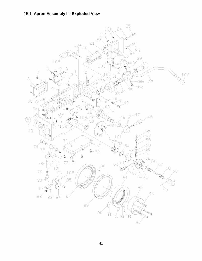
41
15.1 Apron Assembly I – Exploded View
ⅡⅩⅡ
Ⅲ
Ⅷ
Ⅹ
ⅨⅩ
Ⅳ
Ⅰ
ⅩⅠ
Ⅵ
Ⅲ Ⅴ Ⅶ
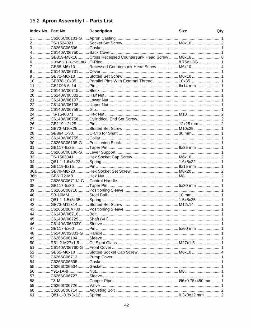
42
15.2 Apron Assembly I – Parts List
Index No. Part No. Description Size Qty
1 ............... C6266C06101-G ...... Apron Casting ...................................................... .................................... 1 2 ............... TS-1524021 ............. Socket Set Screw ................................................. M8x10 ......................... 2 3 ............... C6266C06506 .......... Gasket .................................................................. .................................... 1 4 ............... C6140W06750 ......... Back Cover........................................................... .................................... 1 5 ............... GB819-M8x16 .......... Cross Recessed Countersunk Head Screw ........ M8x16 ......................... 8 6......... ...... GB3452.1-8.75x1.8G .. O-Ring .................................................................. 8.75x1.8G ................... 1 7 ............... GB68-M6x10 ............ Recessed Countersunk Head Screw ................... M6x10 ......................... 4 8 ............... C6140W06731 ......... Cover .................................................................... .................................... 1 9 ............... GB71-M6x10 ............ Slotted Set Screw ................................................ M6x10 ......................... 1 10 ............. GB878-10x35 ........... Parallel Pins With External Thread ...................... 10x35 .......................... 1 11 ............. GB1096-6x14 ........... Pin ........................................................................ 6x14 mm ..................... 1 12 ............. C6140W06715 ......... Block .................................................................... .................................... 1 20 ............. C6140W06302 ......... Half Nut ................................................................ .................................... 1 21 ............. C6140W06107 ......... Lower Nut ............................................................. .................................... 1 22 ............. C6140W06108 ......... Upper Nut ............................................................. .................................... 1 23 ............. C6140W06759 ......... Gib ........................................................................ .................................... 1 24 ............. TS-1540071 ............. Hex Nut ................................................................ M10 ............................. 2 25 ............. C6140W06758 ......... Cylindrical End Set Screw .................................... .................................... 2 26 ............. GB119-12x25 ........... Pin ........................................................................ 12x25 mm ................... 2 27 ............. GB73-M10x25 .......... Slotted Set Screw ................................................ M10x25 ....................... 1 28 ............. GB894.1-30 .............. C-Clip for Shaft .................................................... 30 mm ......................... 1 29 ............. C6140W06755 ......... Collar .................................................................... .................................... 1 30 ............. C6266C06105-G ...... Positioning Block .................................................. .................................... 1 31 ............. GB117-6x35 ............. Taper Pin .............................................................. 6x35 mm ..................... 1 32 ............. C6266C06106-G ...... Lever Support ...................................................... .................................... 1 33 ............. TS-1503041 ............. Hex Socket Cap Screw ........................................ M6x16 ......................... 2 34 ............. Q81-1-1.6x8x22 ....... Spring ................................................................... 1.6x8x22 ..................... 1 35 ............. GB119-8x15 ............. Pin ........................................................................ 8x15 mm ..................... 1 36a ........... GB79-M8x20 ............ Hex Socket Set Screw ......................................... M8x20 ......................... 2 36b ........... GB6172-M8 .............. Hex Nut ................................................................ M8 ............................... 2 37 ............. C6266C06711J-G .... Control Handle ..................................................... .................................... 1 38 ............. GB117-5x30 ............. Taper Pin .............................................................. 5x30 mm ..................... 1 39 ............. C6266C06710 .......... Positioning Sleeve ............................................... .................................... 1 40 ............. SB-10MM ................. Steel Ball .............................................................. 10 mm ......................... 1 41 ............. Q81-1-1.5x8x35 ....... Spring ................................................................... 1.5x8x35 ..................... 1 42 ............. GB73-M12x14 .......... Slotted Set Screw ................................................ M12x14 ....................... 1 43 ............. C6266C06A780 ....... Positioning Sleeve ............................................... .................................... 1 44 ............. C6140W06716 ......... Bolt ....................................................................... .................................... 1 45 ............. C6140W06725 ......... Shaft (VII)............................................................. .................................... 1 46 ............. C6140W06303Y ....... Sleeve .................................................................. .................................... 1 47 ............. GB117-5x60 ............. Pin ........................................................................ 5x60 mm ..................... 1 48 ............. C6140W02801-G ..... Handle .................................................................. .................................... 1 49 ............. C6266C06104 .......... Sleeve .................................................................. .................................... 1 50 ............. R51-2-M27x1.5 ........ Oil Sight Glass ..................................................... M27x1.5 ...................... 1 51 ............. C6140W06760-G ..... Front Cover .......................................................... .................................... 1 52 ............. GB65-M6x10 ............ Slotted Socket Cap Screw ................................... M6x10 ......................... 4 53 ............. C6266C06713 .......... Pump Cover ......................................................... .................................... 1 54 ............. C6266C06505 .......... Gasket .................................................................. .................................... 1 55 ............. C6266C06504 .......... Gasket .................................................................. .................................... 1 56 ............. Y91-1A-8 .................. Nut ........................................................................ M8 ............................... 1 57 ............. C6266C06727 .......... Sleeve .................................................................. .................................... 1 58 ............. T3-M ......................... Copper Pipe ......................................................... Ø6x0.75x450 mm ....... 1 59 ............. C6266C06726 .......... Valve .................................................................... .................................... 1 60 ............. C6266C06714 .......... Adjusting Bolt ....................................................... .................................... 2 61 ............. Q81-1-0.3x3x12 ....... Spring ................................................................... 0.3x3x12 mm .............. 2
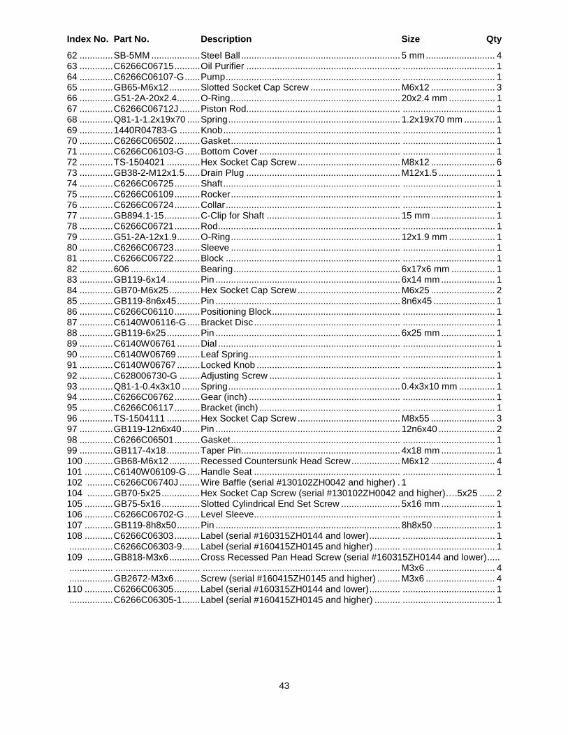
43
Index No. Part No. Description Size Qty
62 ............. SB-5MM ................... Steel Ball .............................................................. 5 mm ........................... 4 63 ............. C6266C06715 .......... Oil Purifier ............................................................ .................................... 1 64 ............. C6266C06107-G ...... Pump .................................................................... .................................... 1 65 ............. GB65-M6x12 ............ Slotted Socket Cap Screw ................................... M6x12 ......................... 3 66 ............. G51-2A-20x2.4 ......... O-Ring .................................................................. 20x2.4 mm .................. 1 67 ............. C6266C06712J ........ Piston Rod............................................................ .................................... 1 68 ............. Q81-1-1.2x19x70 ..... Spring ................................................................... 1.2x19x70 mm ............ 1 69 ............. 1440R04783-G ........ Knob ..................................................................... .................................... 1 70 ............. C6266C06502 .......... Gasket .................................................................. .................................... 1 71 ............. C6266C06103-G ...... Bottom Cover ....................................................... .................................... 1 72 ............. TS-1504021 ............. Hex Socket Cap Screw ........................................ M8x12 ......................... 6 73 ............. GB38-2-M12x1.5 ...... Drain Plug ............................................................ M12x1.5 ...................... 1 74 ............. C6266C06725 .......... Shaft ..................................................................... .................................... 1 75 ............. C6266C06109 .......... Rocker .................................................................. .................................... 1 76 ............. C6266C06724 .......... Collar .................................................................... .................................... 1 77 ............. GB894.1-15 .............. C-Clip for Shaft .................................................... 15 mm ......................... 1 78 ............. C6266C06721 .......... Rod ....................................................................... .................................... 1 79 ............. G51-2A-12x1.9 ......... O-Ring .................................................................. 12x1.9 mm .................. 1 80 ............. C6266C06723 .......... Sleeve .................................................................. .................................... 1 81 ............. C6266C06722 .......... Block .................................................................... .................................... 1 82 ............. 606 ........................... Bearing ................................................................. 6x17x6 mm ................. 1 83 ............. GB119-6x14 ............. Pin ........................................................................ 6x14 mm ..................... 1 84 ............. GB70-M6x25 ............ Hex Socket Cap Screw ........................................ M6x25 ......................... 2 85 ............. GB119-8n6x45 ......... Pin ........................................................................ 8n6x45 ........................ 1 86 ............. C6266C06110 .......... Positioning Block .................................................. .................................... 1 87 ............. C6140W06116-G ..... Bracket Disc ......................................................... .................................... 1 88 ............. GB119-6x25 ............. Pin ........................................................................ 6x25 mm ..................... 1 89 ............. C6140W06761 ......... Dial ....................................................................... .................................... 1 90 ............. C6140W06769 ......... Leaf Spring ........................................................... .................................... 1 91 ............. C6140W06767 ......... Locked Knob ........................................................ .................................... 1 92 ............. C628006730-G ........ Adjusting Screw ................................................... .................................... 1 93 ............. Q81-1-0.4x3x10 ....... Spring ................................................................... 0.4x3x10 mm .............. 1 94 ............. C6266C06762 .......... Gear (inch) ........................................................... .................................... 1 95 ............. C6266C06117 .......... Bracket (inch) ....................................................... .................................... 1 96 ............. TS-1504111 ............. Hex Socket Cap Screw ........................................ M8x55 ......................... 3 97 ............. GB119-12n6x40 ....... Pin ........................................................................ 12n6x40 ...................... 2 98 ............. C6266C06501 .......... Gasket .................................................................. .................................... 1 99 ............. GB117-4x18 ............. Taper Pin .............................................................. 4x18 mm ..................... 1 100 ........... GB68-M6x12 ............ Recessed Countersunk Head Screw ................... M6x12 ......................... 4 101 ........... C6140W06109-G ..... Handle Seat ......................................................... .................................... 1 102 .......... C6266C06740J ........ Wire Baffle (serial #130102ZH0042 and higher) . 1 104 .......... GB70-5x25 ............... Hex Socket Cap Screw (serial #130102ZH0042 and higher)….5x25 ...... 2 105 ........... GB75-5x16 ............... Slotted Cylindrical End Set Screw ....................... 5x16 mm ..................... 1 106 ........... C6266C06702-G ...... Level Sleeve......................................................... .................................... 1 107 ........... GB119-8h8x50 ......... Pin ........................................................................ 8h8x50 ........................ 1 108 ........... C6266C06303 .......... Label (serial #160315ZH0144 and lower) ............ .................................... 1 ................. C6266C06303-9 ....... Label (serial #160415ZH0145 and higher) .......... .................................... 1 109 .......... GB818-M3x6 ............ Cross Recessed Pan Head Screw (serial #160315ZH0144 and lower) ..... ................. ................................. ............................................................................. M3x6 ........................... 4 ................. GB2672-M3x6 .......... Screw (serial #160415ZH0145 and higher) ......... M3x6 ........................... 4 110 ........... C6266C06305 .......... Label (serial #160315ZH0144 and lower) ............ .................................... 1 ................. C6266C06305-1 ....... Label (serial #160415ZH0145 and higher) .......... .................................... 1
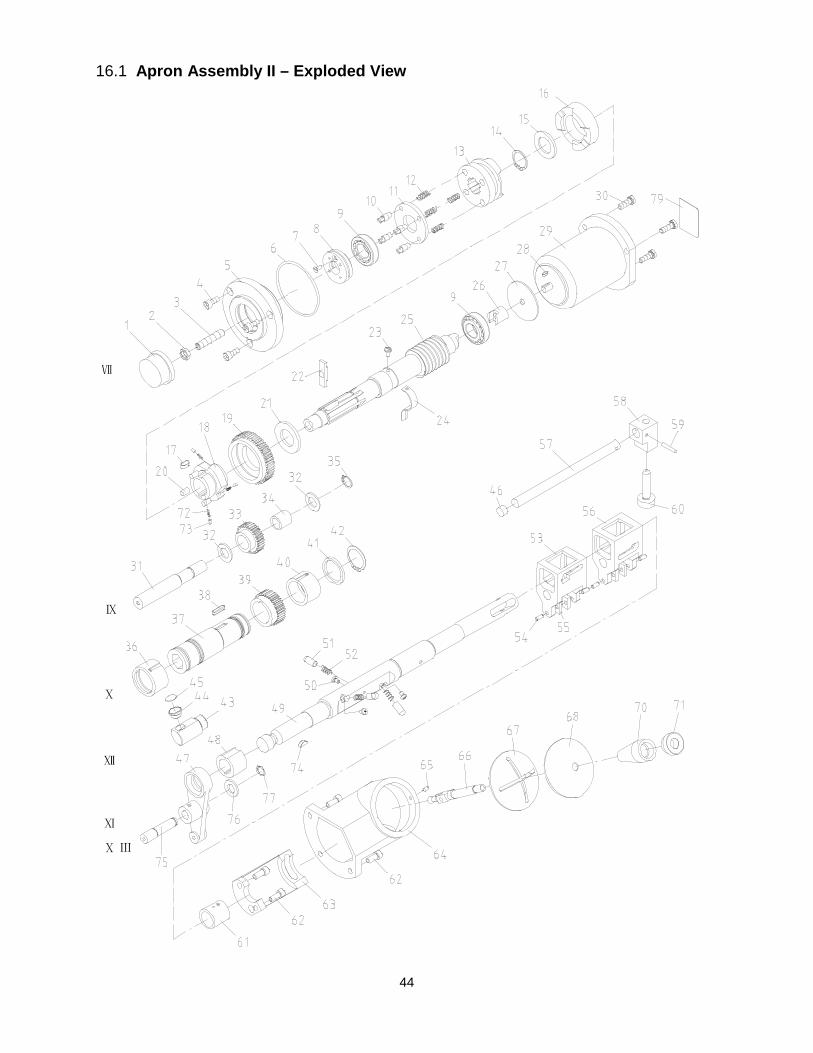
44
16.1 Apron Assembly II – Exploded View
Ⅺ
Ⅹ Ⅲ
Ⅻ
Ⅸ
Ⅹ
Ⅶ
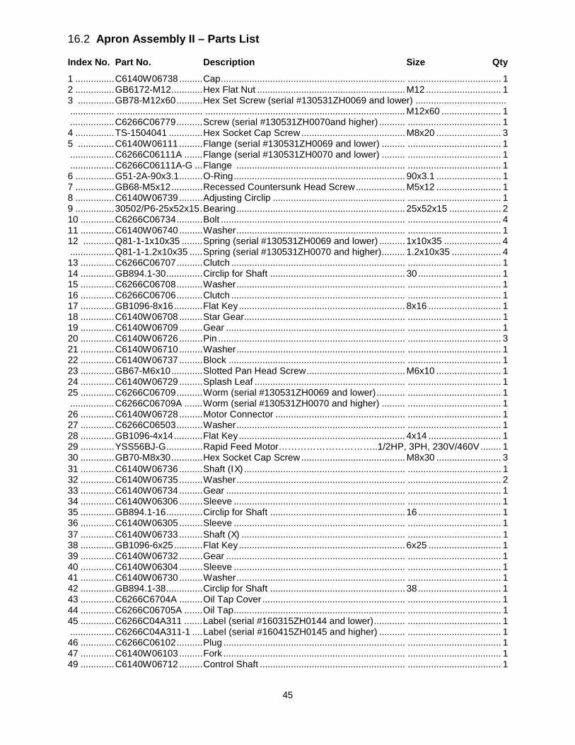
45
16.2 Apron Assembly II – Parts List
Index No. Part No. Description Size Qty
1 ............... C6140W06738 ......... Cap ....................................................................... .................................... 1 2 ............... GB6172-M12 ............ Hex Flat Nut ......................................................... M12 ............................. 1 3 .............. GB78-M12x60 .......... Hex Set Screw (serial #130531ZH0069 and lower) ................................... ................. ................................. ............................................................................. M12x60 ....................... 1 ................. C6266C06779 .......... Screw (serial #130531ZH0070and higher) .......... .................................... 1 4 ............... TS-1504041 ............. Hex Socket Cap Screw ........................................ M8x20 ......................... 3 5 .............. C6140W06111 ......... Flange (serial #130531ZH0069 and lower) ......... .................................... 1 ................. C6266C06111A ....... Flange (serial #130531ZH0070 and lower) ......... .................................... 1 ................. C6266C06111A-G ... Flange ................................................................. .................................... 1 6 ............... G51-2A-90x3.1 ......... O-Ring .................................................................. 90x3.1 ......................... 1 7 ............... GB68-M5x12 ............ Recessed Countersunk Head Screw ................... M5x12 ......................... 1 8 ............... C6140W06739 ......... Adjusting Circlip ................................................... .................................... 1 9 ............... 30502/P6-25x52x15 . Bearing ................................................................. 25x52x15 .................... 2 10 ............. C6266C06734 .......... Bolt ....................................................................... .................................... 4 11 ............. C6140W06740 ......... Washer ................................................................. .................................... 1 12 ............ Q81-1-1x10x35 ........ Spring (serial #130531ZH0069 and lower) .......... 1x10x35 ...................... 4 ................. Q81-1-1.2x10x35 ..... Spring (serial #130531ZH0070 and higher) ......... 1.2x10x35 ................... 4 13 ............. C6266C06707 .......... Clutch ................................................................... .................................... 1 14 ............. GB894.1-30 .............. Circlip for Shaft .................................................... 30 ................................ 1 15 ............. C6266C06708 .......... Washer ................................................................. .................................... 1 16 ............. C6266C06706 .......... Clutch ................................................................... .................................... 1 17 ............. GB1096-8x16 ........... Flat Key ................................................................ 8x16 ............................ 1 18 ............. C6140W06708 ......... Star Gear .............................................................. .................................... 1 19 ............. C6140W06709 ......... Gear ..................................................................... .................................... 1 20 ............. C6140W06726 ......... Pin ........................................................................ .................................... 3 21 ............. C6140W06710 ......... Washer ................................................................. .................................... 1 22 ............. C6140W06737 ......... Block .................................................................... .................................... 1 23 ............. GB67-M6x10 ............ Slotted Pan Head Screw ...................................... M6x10 ......................... 1 24 ............. C6140W06729 ......... Splash Leaf .......................................................... .................................... 1 25 ............. C6266C06709 .......... Worm (serial #130531ZH0069 and lower) ........... .................................... 1 ................. C6266C06709A ....... Worm (serial #130531ZH0070 and higher) ......... .................................... 1 26 ............. C6140W06728 ......... Motor Connector .................................................. .................................... 1 27 ............. C6266C06503 .......... Washer ................................................................. .................................... 1 28 ............. GB1096-4x14 ........... Flat Key ................................................................ 4x14 ............................ 1 29 ............. YSS56BJ-G .............. Rapid Feed Motor…………………………..1/2HP, 3PH, 230V/460V ........ 1 30 ............. GB70-M8x30 ............ Hex Socket Cap Screw ........................................ M8x30 ......................... 3 31 ............. C6140W06736 ......... Shaft (IX) .............................................................. .................................... 1 32 ............. C6140W06735 ......... Washer ................................................................. .................................... 2 33 ............. C6140W06734 ......... Gear ..................................................................... .................................... 1 34 ............. C6140W06306 ......... Sleeve .................................................................. .................................... 1 35 ............. GB894.1-16 .............. Circlip for Shaft .................................................... 16 ................................ 1 36 ............. C6140W06305 ......... Sleeve .................................................................. .................................... 1 37 ............. C6140W06733 ......... Shaft (X) ............................................................... .................................... 1 38 ............. GB1096-6x25 ........... Flat Key ................................................................ 6x25 ............................ 1 39 ............. C6140W06732 ......... Gear ..................................................................... .................................... 1 40 ............. C6140W06304 ......... Sleeve .................................................................. .................................... 1 41 ............. C6140W06730 ......... Washer ................................................................. .................................... 1 42 ............. GB894.1-38 .............. Circlip for Shaft .................................................... 38 ................................ 1 43 ............. C6266C6704A ......... Oil Tap Cover ....................................................... .................................... 1 44 ............. C6266C06705A ....... Oil Tap .................................................................. .................................... 1 45 ............. C6266C04A311 ....... Label (serial #160315ZH0144 and lower) ............ .................................... 1 ................. C6266C04A311-1 .... Label (serial #160415ZH0145 and higher) .......... .................................... 1 46 ............. C6266C06102 .......... Plug ...................................................................... .................................... 1 47 ............. C6140W06103 ......... Fork ...................................................................... .................................... 1 49 ............. C6140W06712 ......... Control Shaft ........................................................ .................................... 1
46
Index No. Part No. Description Size Qty
50 ............. GB67-M6x8 .............. Slotted Pan Head Screw ...................................... M6x8 ........................... 3 51 ............. C6140W06701 ......... Pin ........................................................................ .................................... 3 52 ............. Q81-1-1.6x8x22 ....... Spring ................................................................... 1.6x8x22 ..................... 3 53 ............. C6140W06713 ......... Fork ...................................................................... .................................... 1 54 ............. GB119-6n6x14 ......... Pin ........................................................................ 6n6x14 ........................ 6 55 ............. C6140W06715 ......... Sliding Block......................................................... .................................... 6 56 ............. C6140W06714 ......... Right Fork ............................................................. .................................... 1 57 ............. C6140W06717 ......... Shaft ..................................................................... .................................... 1 58 ............. C6140W06104 ......... Interlocking Block ................................................. .................................... 1 59 ............. GB117-5x30 ............. Taper Pin .............................................................. 5x30 ............................ 1 60 ............. C6140W06718 ......... Shaft ..................................................................... .................................... 1 61 ............. C626C06304 ............ Sleeve .................................................................. .................................... 1 62 ............. TS-1504041 ............. Hex Socket Cap Screw ........................................ M8x20 ......................... 5 63 ............. C6140W06719 ......... Bracket ................................................................. .................................... 1 64 ............. C6140W06105-G ..... Bracket ................................................................. .................................... 1 65 ............. GB71-M6x10 ............ Slotted Set Screw ................................................ M6x10 ......................... 1 66. ............ C6140W06722A-G ... Handle .................................................................. .................................... 1 67 ............. C6140W06106-G ..... Cross Cover ......................................................... .................................... 1 68 ............. C6140W06501 ......... Washer ................................................................. .................................... 1 69 ............. GB119-8x25 ............. Pin ........................................................................ 8x25 ............................ 1 70 ............. C6140W06721A-G ... Handle .................................................................. .................................... 1 71 ............. C6140W06720A-G ... Seat ...................................................................... .................................... 1 72 ............. Q81-1-0.3x3x12 ....... Spring ................................................................... 0.3x3x12 ..................... 3 73 ............. C6140W06727 ......... Pin ........................................................................ .................................... 3 75 ............. C6140W06704 ......... Shaft (XIII) ............................................................ .................................... 1 76 ............. C6140W06705 ......... Collar .................................................................... .................................... 1 77 ............. GB894.1-14 .............. C-clip For Shaft .................................................... 14 ................................ 1 78 ............. GB71-M5x6 .............. Slotted Set Screw ................................................ M5x6 ........................... 1 79 ............. C6266C18518-17 ..... Motor Label (serial #160415ZH0145 and higher) 1
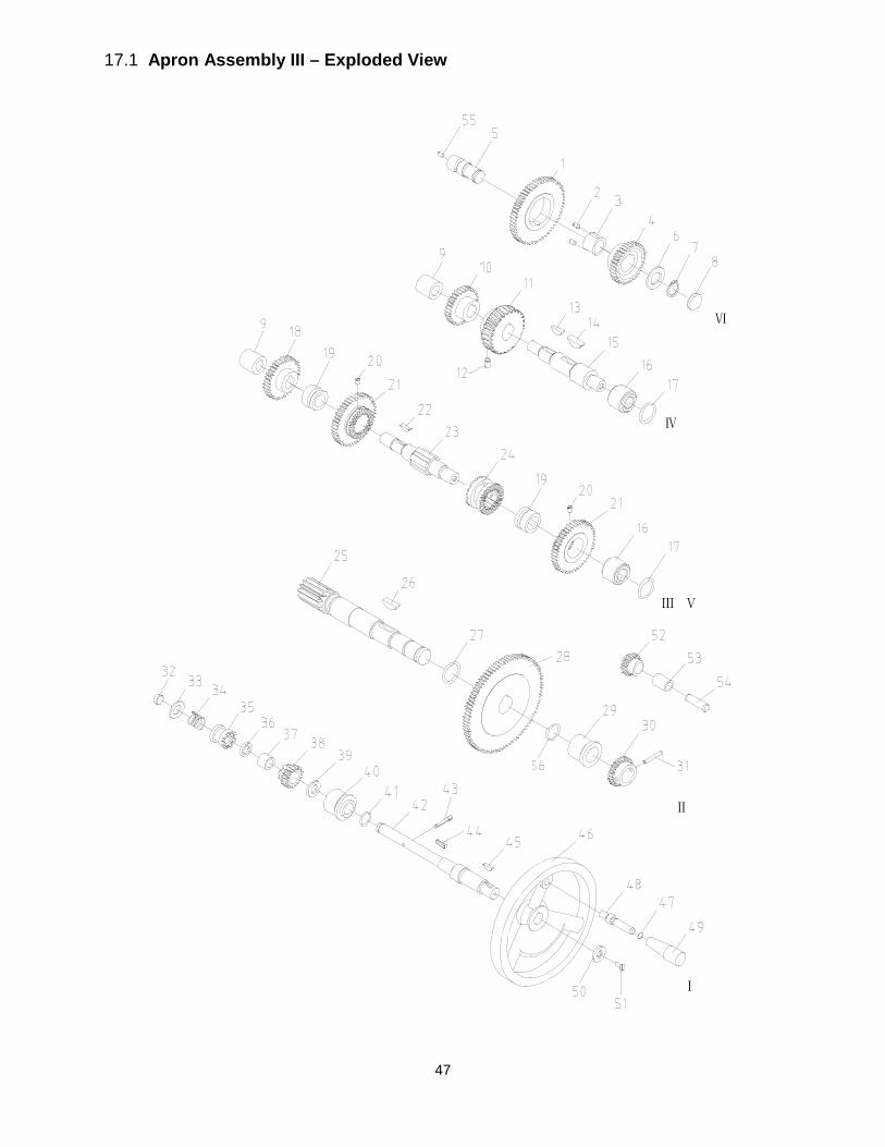
47
17.1 Apron Assembly III – Exploded View
Ⅰ
Ⅱ
ⅤⅢ
Ⅳ
Ⅵ
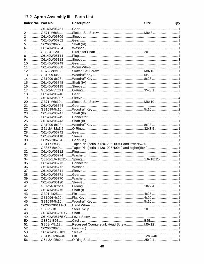
48
17.2 Apron Assembly III – Parts List Index No. Part No. Description Size Qty 1 ............... C6140W06751 ......... Gear ..................................................................... .................................... 1 2 ............... GB71-M6x8 .............. Slotted Set Screw ................................................ M6x8 ........................... 2 3 ............... C6140W06309 ......... Sleeve .................................................................. .................................... 1 4 ............... C6140W06752 ......... Gear ..................................................................... .................................... 1 5 ............... C6266C06728 .......... Shaft (VI) .............................................................. .................................... 1 6 ............... C6140W06754 ......... Washer ................................................................. .................................... 1 7 ............... GB894.1-20 .............. Circlip for Shaft .................................................... 20 ................................ 1 8 ............... C6140W06114 ......... Plug ...................................................................... .................................... 1 9 ............... C6140W06113 ......... Sleeve .................................................................. .................................... 3 10 ............. C6140W06749 ......... Gear ..................................................................... .................................... 1 11 ............. C6140W06308 ......... Worm Wheel ........................................................ .................................... 1 12 ............. GB72-M8x16 ............ Slotted Set Screw ................................................ M8x16 ......................... 1 13 ............. GB1099-6x22 ........... Woodruff Key ....................................................... 6x22 ............................ 1 14 ............. GB1099-8x28 ........... Woodruff Key ....................................................... 8x28 ............................ 1 15 ............. C6140W06748 ......... Shaft (IV) .............................................................. .................................... 1 16 ............. C6140W06115 ......... Sleeve .................................................................. .................................... 3 17 ............. G51-2A-35x3.1 ......... O-Ring .................................................................. 35x3.1 ......................... 3 18 ............. C6140W06746 ......... Gear ..................................................................... .................................... 2 19 ............. C6140W06307 ......... Sleeve .................................................................. .................................... 4 20 ............. GB71-M6x10 ............ Slotted Set Screw ................................................ M6x10 ......................... 4 21 ............. C6140W06744 ......... Gear ..................................................................... .................................... 4 22 ............. GB1099-5x16 ........... Woodruff Key ....................................................... 5x16 ............................ 2 23 ............. C6140W06747 ......... Shaft (III) .............................................................. .................................... 2 24 ............. C6140W06745 ......... Connector............................................................. .................................... 2 25 ............. C6140W06743 ......... Shaft (II) ............................................................... .................................... 1 26 ............. GB1099-8x28 ........... Woodruff Key ....................................................... 8x28 ............................ 1 27 ............. G51-2A-32x3.5 ......... O-Ring .................................................................. 32x3.5 ......................... 1 28 ............. C6140W06742 ......... Gear ..................................................................... .................................... 1 29 ............. C6140W06118 ......... Sleeve .................................................................. .................................... 1 30 ............. C6266C06764 .......... Gear (in.) .............................................................. .................................... 1 31 ............. GB117-5x35 ............. Taper Pin (serial #120720ZH0041 and lower)5x35 .................................. 1 ................. GB877-5x40 ............. Taper Pin (serial #130102ZH0042 and higher)5x40 ................................ 1 32 ............. C6140W06112 ......... Plug ...................................................................... .................................... 1 33 ............. C6140W06774 ......... Washer ................................................................. .................................... 1 34 ............. Q81-1-1.6x18x25 ..... Spring ................................................................... 1.6x18x25 ................... 1 35 ............. C6140W06773 ......... Connector............................................................. .................................... 1 36 ............. C6140W06772 ......... Washer ................................................................. .................................... 1 37 ............. C6140W06311 ......... Sleeve .................................................................. .................................... 1 38 ............. C6140W06771 ......... Gear ..................................................................... .................................... 1 39 ............. C6140W06770 ......... Washer ................................................................. .................................... 1 40 ............. C6140W06120 ......... Sleeve .................................................................. .................................... 1 41 ............. G51-2A-18x2.4 ......... O-Ring l ................................................................ 18x2.4 ......................... 1 42 ............. C6140W06775 ......... Shaft (I) ................................................................ .................................... 1 43 ............. GB91-4x25 ............... Pin ........................................................................ 4x25 ............................ 1 44 ............. GB1096-4x20 ........... Flat Key ................................................................ 4x20 ............................ 1 45 ............. GB1099-5x16 ........... Woodruff Key ....................................................... 5x16 ............................ 1 46 ............. C6266C06111-G ...... Hand Wheel ......................................................... .................................... 1 47 ............. GB895-10 ................. Steel C-clip ........................................................... 10 ................................ 1 48 ............. C6140W06766-G ..... Shaft ..................................................................... .................................... 1 49 ............. C6140W06765-G ..... Lever Sleeve ........................................................ .................................... 1 50 ............. GB891-B25 .............. Circlip ................................................................... B25 .............................. 1 51 ............. GB68-M5x12 ............ Recessed Countersunk Head Screw ................... M5x12 ......................... 1 52 ............. C6266C06763 .......... Gear (in.) .............................................................. .................................... 1 53 ............. C6140W06310Y ....... Sleeve .................................................................. .................................... 1 54 ............. GB119-12n6x40 ....... Pin ........................................................................ 12n6x40 ...................... 1 56 ............. G51-2A-25x2.4 ......... O Ring Seal .......................................................... 25x2.4 ......................... 1
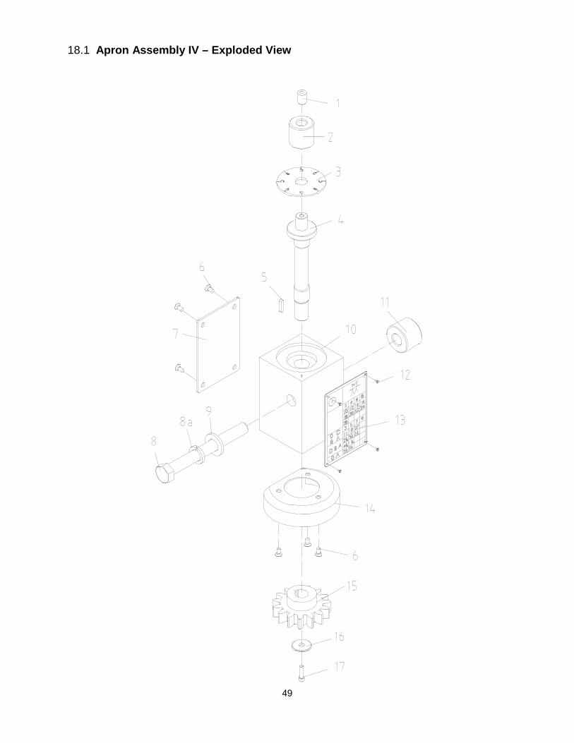
49
18.1 Apron Assembly IV – Exploded View
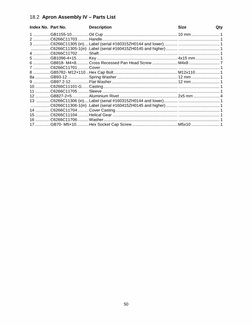
50
18.2 Apron Assembly IV – Parts List
Index No. Part No. Description Size Qty
1 ............... GB1155-10 ............... Oil Cup ................................................................. 10 mm ......................... 1 2 ............... C6266C11703 .......... Handle .................................................................. .................................... 1 3 ............... C6266C11305 (in) .... Label (serial #160315ZH0144 and lower) ............ .................................... 1 ................. C6266C11305-1(in) . Label (serial #160415ZH0145 and higher) .......... .................................... 1 4 ............... C6266C11702 .......... Shaft ..................................................................... .................................... 1 5 ............... GB1096-4×15........... Key ....................................................................... 4x15 mm ..................... 1 6 ............... GB818- M4×8........... Cross Recessed Pan Head Screw ...................... M4x8 ........................... 7 7 ............... C6266C11701 .......... Cover .................................................................... .................................... 1 8 ............... GB5782- M12×110 .. Hex Cap Bolt ........................................................ M12x110 ..................... 1 8a ............. GB93-12 ................... Spring Washer ..................................................... 12 mm ......................... 1 9 ............... GB97.2-12 ................ Flat Washer .......................................................... 12 mm ......................... 1 10 ............. C6266C11101-G ...... Casting ................................................................. .................................... 1 11 ............. C6266C11705 .......... Sleeve .................................................................. .................................... 1 12 ............. GB827-2×5............... Aluminium Rivet ................................................... 2x5 mm ....................... 4 13 ............ C6266C11306 (in) .... Label (serial #160315ZH0144 and lower) ............ .................................... 1 ................. C6266C11306-1(in) . Label (serial #160415ZH0145 and higher) .......... .................................... 1 14 ............. C6266C11704 .......... Cover Casting ...................................................... .................................... 1 15 ............. C6266C11104 .......... Helical Gear ......................................................... .................................... 1 16 ............. C6266C11706 .......... Washer ................................................................. .................................... 1 17 ............. GB70- M5×10........... Hex Socket Cap Screw ........................................ M5x10 ......................... 1
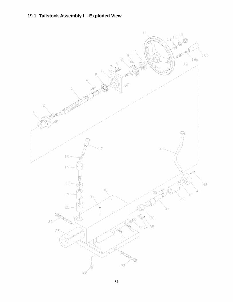
51
19.1 Tailstock Assembly I – Exploded View
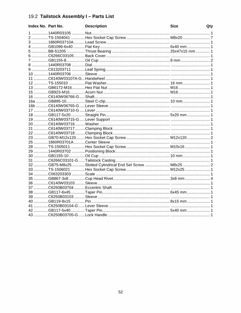
52
19.2 Tailstock Assembly I – Parts List
Index No. Part No. Description Size Qty
1 ............... 1440R03105 ............ Nut ........................................................................ .................................... 1 2 ............... TS-1504041 ............. Hex Socket Cap Screw ........................................ M8x20 ......................... 7 3 ............... 1860R03710A .......... Lead Screw .......................................................... .................................... 1 4 ............... GB1096-6x40 ........... Flat Key ................................................................ 6x40 mm ..................... 1 5 ............... BB-51205 ................. Thrust Bearing ..................................................... 25x47x15 mm ............. 1 6 ............... C6266C03105 .......... Back Cover........................................................... .................................... 1 7 ............... GB1155-8 ................. Oil Cup ................................................................. 8 mm ........................... 2 8 ............... 1440R03708 ............ Dial ....................................................................... .................................... 1 9 ............... C613203711 ............ Leaf Spring ........................................................... .................................... 1 10 ............. 1440R03706 ............ Sleeve .................................................................. .................................... 1 11 ............. C6140W03107A-G ... Handwheel ........................................................... .................................... 1 12 ............. TS-155010 ............... Flat Washer .......................................................... 16 mm ......................... 1 13 ............. GB6172-M16 ............ Hex Flat Nut ......................................................... M16 ............................. 1 15 ............. GB923-M16 .............. Acorn Nut ............................................................. M16 ............................. 1 16 ............. C6140W06766-G ..... Shaft ..................................................................... .................................... 1 16a ........... GB895-10 ................. Steel C-clip ........................................................... 10 mm ......................... 1 16b ........... C6140W06765-G ..... Lever Sleeve ........................................................ .................................... 1 17 ............. C6140W03710-G ..... Lever .................................................................... .................................... 1 18 ............. GB117-5x20 ............. Straight Pin........................................................... 5x20 mm ..................... 1 19 ............. C6140W03715-G ..... Lever Support ...................................................... .................................... 1 20 ............. C6140W03716 ......... Washer ................................................................. .................................... 1 21 ............. C6140W03717 ......... Clamping Block .................................................... .................................... 1 22 ............. C6140W03718 ......... Clamping Block .................................................... .................................... 1 23 ............. GB70-M12x120 ........ Hex Socket Cap Screw ........................................ M12x120 ..................... 2 25 ............. 1860R03701A .......... Center Sleeve ...................................................... .................................... 1 28 ............. TS-1505011 ............. Hex Socket Cap Screw ........................................ M10x16 ....................... 1 29 ............. 1440R03702 ............ Positioning Block .................................................. .................................... 1 30 ............. GB1155-10 ............... Oil Cup ................................................................. 10 mm ......................... 1 31 ............. C6266C03101-G ...... Tailstock Casting .................................................. .................................... 1 32 ............. GB75-M8x25 ............ Slotted Cylindrical End Set Screw ....................... M8x25 ......................... 2 33 ............. TS-1506021 ............. Hex Socket Cap Screw ........................................ M12x25 ....................... 1 34 ............. C063203303 ............ Scale .................................................................... .................................... 1 35 ............. GB867-3x8 ............... Cup Head Rivet .................................................... 3x8 mm ....................... 4 36 ............. C6140W03103 ......... Sleeve .................................................................. .................................... 1 37 ............. C6250B03704 .......... Eccentric Shaft ..................................................... .................................... 1 38 ............. GB117-6x45 ............. Taper Pin .............................................................. 6x45 mm ..................... 1 39 ............. C6250B03103 .......... Sleeve .................................................................. .................................... 1 40 ............. GB119-8x15 ............. Pin ........................................................................ 8x15 mm ..................... 1 41 ............. C6250B03104-G ...... Lever Sleeve ........................................................ .................................... 1 42 ............. GB117-5x40 ............. Taper Pin .............................................................. 5x40 mm ..................... 1 43 ............. C6250B03705-G ...... Lock Handle ......................................................... .................................... 1
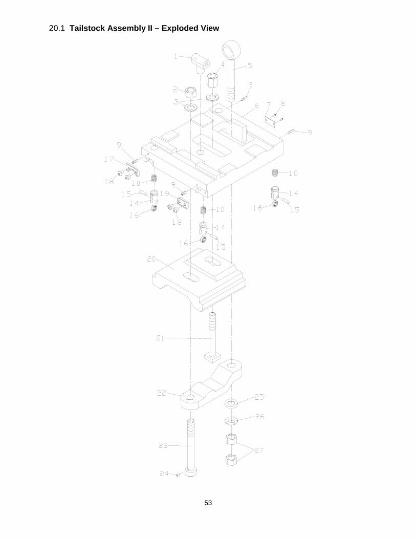
53
20.1 Tailstock Assembly II – Exploded View

54
20.2 Tailstock Assembly II – Parts List
Index No. Part No. Description Size Qty
1 ............... C6140W03110 ......... Nut ........................................................................ .................................... 1 2 ............... GB6171-M20x1.5 ..... Hex Nut ................................................................ M20x1.5 ...................... 1 3 ............... TS-1550111 ............. Flat Washer .......................................................... 20 mm ......................... 1 4 ............... GB56-M20 ................ Hex Thick Nut....................................................... M20 ............................. 1 5 ............... C6266C03703 .......... Pulling Rod ........................................................... .................................... 1 6 ............... C6266C03102-G ...... Sliding Base ......................................................... .................................... 1 7 ............... C063203304 ............ Sign Plate ............................................................. .................................... 1 8 ............... GB867-3x8 ............... Half Circle Rivet ................................................... 3x8 mm ....................... 4 9 ............... GB75-M6x16 ............ Slotted Cylindrical End Set Screw ....................... M6x16 ......................... 4 10 ............. GB2089-1.8x14x18 .. Spring ................................................................... .................................... 4 14 ............. C6140W03713 ......... Bearing Support ................................................... .................................... 4 15 ............. C6140W03714 ......... Small Axle ............................................................ .................................... 4 16 ............. BB-607ZZ ................. Ball Bearing .......................................................... 7x19x6 mm ................. 4 17 ............. C6140W03502 ......... Wipe Plate ............................................................ .................................... 1 18 ............. TS-1534032 ............. Phillips Pan Head Machine Screw (serial #160315ZH0144 and lower) ..... ................. ................................. ............................................................................. M6x10 ......................... 4 ................. GB2672-M6x10 ........ Screw (serial #160415ZH0145 and higher) ......... M6x10 ......................... 4 19 ............. C6140W03503 ......... Wipe Plate ............................................................ .................................... 1 20 ............. C6140W03104-G ..... Clamping Block .................................................... .................................... 1 21 ............. C6266C03702 .......... Screw ................................................................... .................................... 1 22 ............. C6140W03111-G ..... Clamping Block .................................................... .................................... 1 23 ............. C6266C03701 .......... Screw ................................................................... .................................... 1 24 ............. GB119-5x10 ............. Straight Pin........................................................... 5x10 mm ..................... 1 25 ............. GB850-20 ................. Taper Washer ...................................................... 20 mm ......................... 1 26 ............. GB849-20 ................. Ball Washer .......................................................... 20 mm ......................... 1 27 ............. GB6173-M20x1.5 ..... Hex Nut ................................................................ M20x1.5 ...................... 2
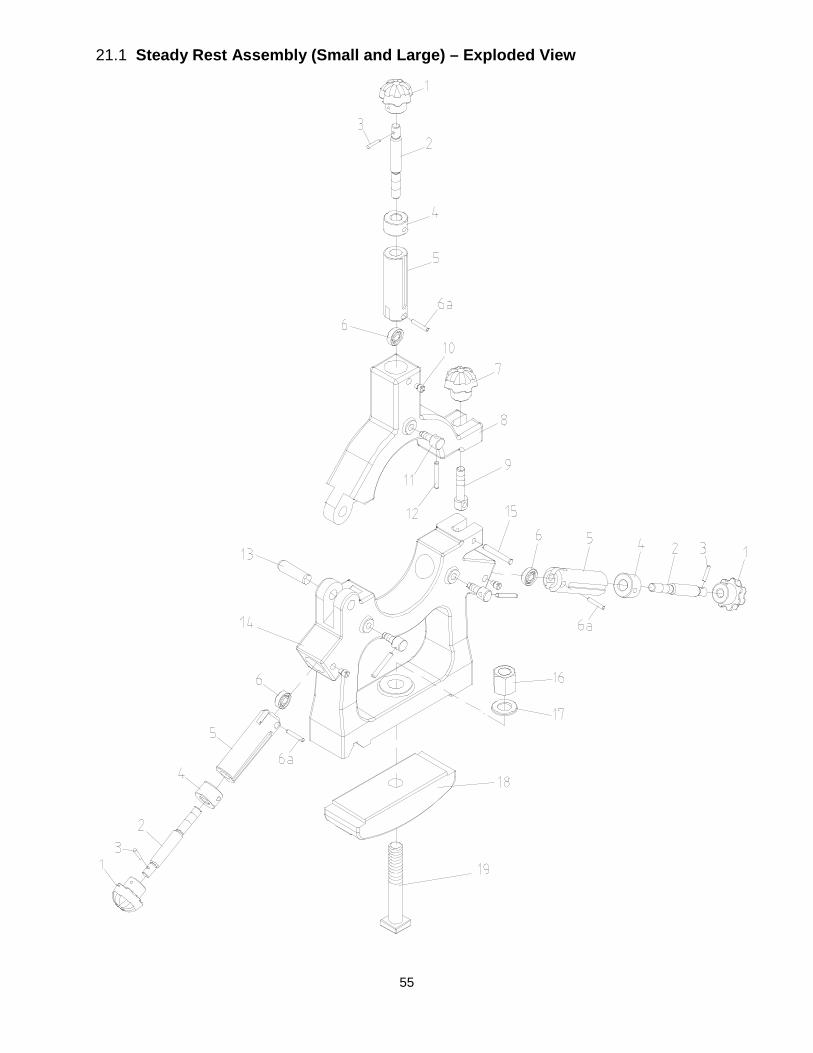
55
21.1 Steady Rest Assembly (Small and Large) – Exploded View
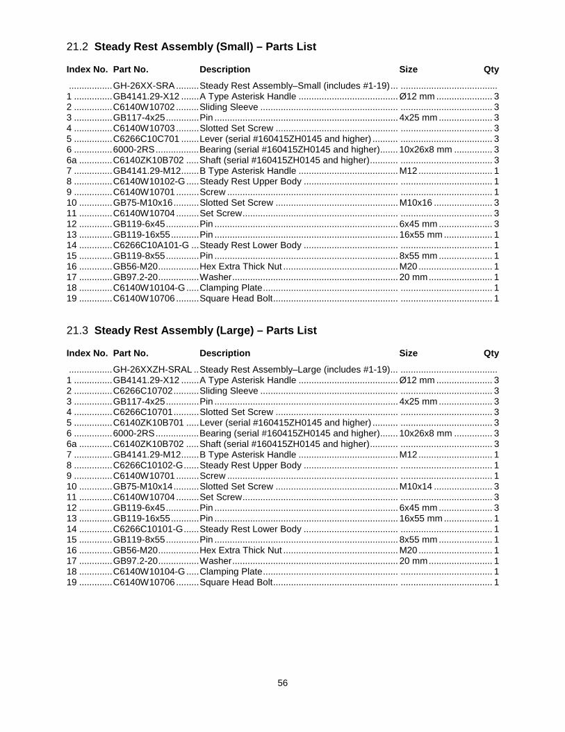
56
21.2 Steady Rest Assembly (Small) – Parts List
Index No. Part No. Description Size Qty
................. GH-26XX-SRA ......... Steady Rest Assembly–Small (includes #1-19) ... ...................................... 1 ............... GB4141.29-X12 ....... A Type Asterisk Handle ....................................... Ø12 mm ...................... 3 2 ............... C6140W10702 ......... Sliding Sleeve ...................................................... .................................... 3 3 ............... GB117-4x25 ............. Pin ........................................................................ 4x25 mm ..................... 3 4 ............... C6140W10703 ......... Slotted Set Screw ................................................ .................................... 3 5 ............... C6266C10C701 ....... Lever (serial #160415ZH0145 and higher) .......... .................................... 3 6 ............... 6000-2RS ................. Bearing (serial #160415ZH0145 and higher) ....... 10x26x8 mm ............... 3 6a ............. C6140ZK10B702 ..... Shaft (serial #160415ZH0145 and higher) ........... .................................... 3 7 ............... GB4141.29-M12 ....... B Type Asterisk Handle ....................................... M12 ............................. 1 8 ............... C6140W10102-G ..... Steady Rest Upper Body ..................................... .................................... 1 9 ............... C6140W10701 ......... Screw ................................................................... .................................... 1 10 ............. GB75-M10x16 .......... Slotted Set Screw ................................................ M10x16 ....................... 3 11 ............. C6140W10704 ......... Set Screw ............................................................. .................................... 3 12 ............. GB119-6x45 ............. Pin ........................................................................ 6x45 mm ..................... 3 13 ............. GB119-16x55 ........... Pin ........................................................................ 16x55 mm ................... 1 14 ............. C6266C10A101-G ... Steady Rest Lower Body ..................................... .................................... 1 15 ............. GB119-8x55 ............. Pin ........................................................................ 8x55 mm ..................... 1 16 ............. GB56-M20 ................ Hex Extra Thick Nut ............................................. M20 ............................. 1 17 ............. GB97.2-20 ................ Washer ................................................................. 20 mm ......................... 1 18 ............. C6140W10104-G ..... Clamping Plate ..................................................... .................................... 1 19 ............. C6140W10706 ......... Square Head Bolt ................................................. .................................... 1
21.3 Steady Rest Assembly (Large) – Parts List
Index No. Part No. Description Size Qty
................. GH-26XXZH-SRAL .. Steady Rest Assembly–Large (includes #1-19) ... ...................................... 1 ............... GB4141.29-X12 ....... A Type Asterisk Handle ....................................... Ø12 mm ...................... 3 2 ............... C6266C10702 .......... Sliding Sleeve ...................................................... .................................... 3 3 ............... GB117-4x25 ............. Pin ........................................................................ 4x25 mm ..................... 3 4 ............... C6266C10701 .......... Slotted Set Screw ................................................ .................................... 3 5 ............... C6140ZK10B701 ..... Lever (serial #160415ZH0145 and higher) .......... .................................... 3 6 ............... 6000-2RS ................. Bearing (serial #160415ZH0145 and higher) ....... 10x26x8 mm ............... 3 6a ............. C6140ZK10B702 ..... Shaft (serial #160415ZH0145 and higher) ........... .................................... 3 7 ............... GB4141.29-M12 ....... B Type Asterisk Handle ....................................... M12 ............................. 1 8 ............... C6266C10102-G ...... Steady Rest Upper Body ..................................... .................................... 1 9 ............... C6140W10701 ......... Screw ................................................................... .................................... 1 10 ............. GB75-M10x14 .......... Slotted Set Screw ................................................ M10x14 ....................... 3 11 ............. C6140W10704 ......... Set Screw ............................................................. .................................... 3 12 ............. GB119-6x45 ............. Pin ........................................................................ 6x45 mm ..................... 3 13 ............. GB119-16x55 ........... Pin ........................................................................ 16x55 mm ................... 1 14 ............. C6266C10101-G ...... Steady Rest Lower Body ..................................... .................................... 1 15 ............. GB119-8x55 ............. Pin ........................................................................ 8x55 mm ..................... 1 16 ............. GB56-M20 ................ Hex Extra Thick Nut ............................................. M20 ............................. 1 17 ............. GB97.2-20 ................ Washer ................................................................. 20 mm ......................... 1 18 ............. C6140W10104-G ..... Clamping Plate ..................................................... .................................... 1 19 ............. C6140W10706 ......... Square Head Bolt ................................................. .................................... 1
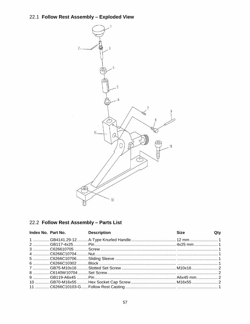
57
22.1 Follow Rest Assembly – Exploded View
22.2 Follow Rest Assembly – Parts List
Index No. Part No. Description Size Qty
1 ............... GB4141.29-12 .......... A-Type Knurled Handle ........................................ 12 mm ......................... 1 2 ............... GB117-4x25 ............. Pin ........................................................................ 4x25 mm ..................... 1 3 ............... C626610705 ............ Screw ................................................................... .................................... 1 4 ............... C6266C10704 .......... Nut ........................................................................ .................................... 1 5 ............... C6266C10706 .......... Sliding Sleeve ...................................................... .................................... 1 6 ............... C6266C10302 .......... Block .................................................................... .................................... 1 7 ............... GB75-M10x16 .......... Slotted Set Screw ................................................ M10x16 ....................... 2 8 ............... C6140W10704 ......... Set Screw ............................................................. .................................... 2 9 ............... GB119-A6x45 .......... Pin ........................................................................ A6x45 mm ................... 2 10 ............. GB70-M16x55 .......... Hex Socket Cap Screw ........................................ M16x55 ....................... 2 11 ............. C6266C10103-G ...... Follow Rest Casting ............................................. .................................... 1
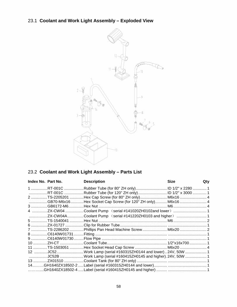
58
23.1 Coolant and Work Light Assembly – Exploded View
23.2 Coolant and Work Light Assembly – Parts List
Index No. Part No. Description Size Qty
1 ............... RT-001C .................. Rubber Tube (for 80” ZH only) ............................. ID 1/2" x 2280 ............. 1 ................. RT-001C .................. Rubber Tube (for 120” ZH only) ........................... ID 1/2" x 3000 ............. 1 2 ............... TS-2205201 ............. Hex Cap Screw (for 80” ZH only) ......................... M6x16 ......................... 4 ................. GB70-M6x16 ............ Hex Socket Cap Screw (for 120” ZH only) ........... M6x16 ......................... 4 3 ............... GB6172-M6 .............. Hex Nut ................................................................ M6 ............................... 4 4 .............. ZX-CW04 ................. Coolant Pump (serial #141020ZH0102and lower) ............................... 1 ................. ZX-CW04A ............... Coolant Pump (serial #141220ZH0103 and higher) ............................ 1 5 ............... TS-1540041 ............. Hex Nut ................................................................ M6 ............................... 2 6 ............... ZX-01727 ................. Clip for Rubber Tube ............................................ .................................... 1 7 ............... TS-2286202 ............. Phillips Pan Head Machine Screw ....................... M6x20 ......................... 2 8 ............... C6140W01731 ......... Fitting ................................................................... .................................... 1 9 ............... C6140W01730 ......... Flow Pipe ............................................................. .................................... 1 10 ............. ZH-CT ...................... Coolant Tube........................................................ 1/2"x16x700 ................ 1 11 ............. TS-1503051 ............. Hex Socket Head Cap Screw .............................. M6x20 ......................... 4 12 ............ JC52 ......................... Work Lamp (serial #160315ZH0144 and lower) .. 24V, 50W .................... 1 ................. JC52B ...................... Work Lamp (serial #160415ZH0145 and higher). 24V, 50W .................... 1 13 ............. ZX01510 .................. Coolant Tank (for 80” ZH only) ............................ .................................... 1 14………GH1640ZX18502-2 ..... Label (serial #160315ZH0144 and lower) ............ .................................... 1 ………....GH1640ZX18502-4 ..... Label (serial #160415ZH0145 and higher) .......... .................................... 1
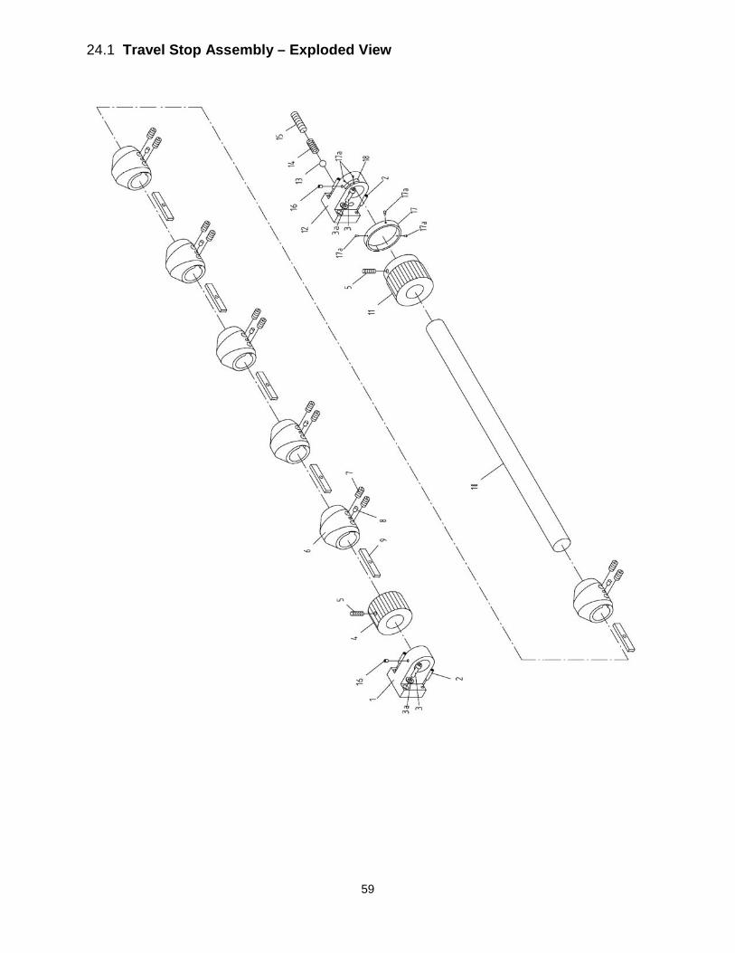
59
24.1 Travel Stop Assembly – Exploded View
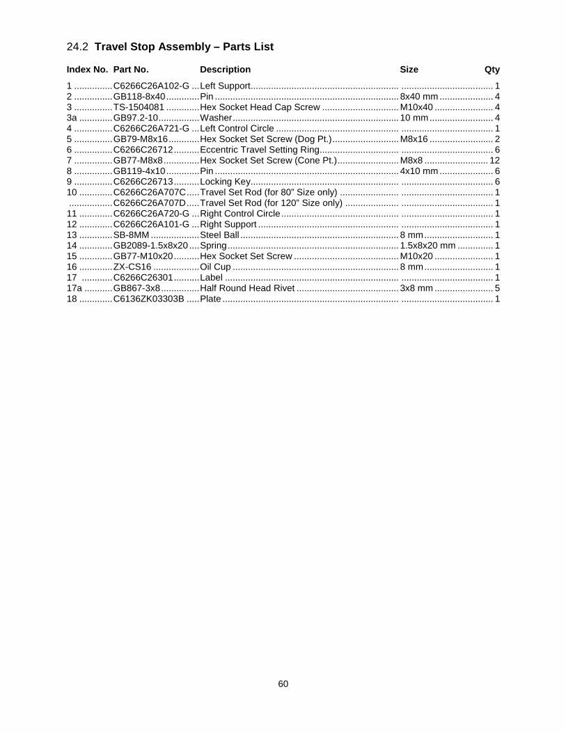
60
24.2 Travel Stop Assembly – Parts List
Index No. Part No. Description Size Qty
1 ............... C6266C26A102-G ... Left Support.......................................................... .................................... 1 2 ............... GB118-8x40 ............. Pin ........................................................................ 8x40 mm ..................... 4 3 ............... TS-1504081 ............. Hex Socket Head Cap Screw .............................. M10x40 ....................... 4 3a ............. GB97.2-10 ................ Washer ................................................................. 10 mm ......................... 4 4 ............... C6266C26A721-G ... Left Control Circle ................................................ .................................... 1 5 ............... GB79-M8x16 ............ Hex Socket Set Screw (Dog Pt.) .......................... M8x16 ......................... 2 6 ............... C6266C26712 .......... Eccentric Travel Setting Ring............................... .................................... 6 7 ............... GB77-M8x8 .............. Hex Socket Set Screw (Cone Pt.) ........................ M8x8 ......................... 12 8 ............... GB119-4x10 ............. Pin ........................................................................ 4x10 mm ..................... 6 9 ............... C6266C26713 .......... Locking Key.......................................................... .................................... 6 10 ............. C6266C26A707C ..... Travel Set Rod (for 80” Size only) ....................... .................................... 1 ................. C6266C26A707D ..... Travel Set Rod (for 120” Size only) ..................... .................................... 1 11 ............. C6266C26A720-G ... Right Control Circle .............................................. .................................... 1 12 ............. C6266C26A101-G ... Right Support ....................................................... .................................... 1 13 ............. SB-8MM ................... Steel Ball .............................................................. 8 mm ........................... 1 14 ............. GB2089-1.5x8x20 .... Spring ................................................................... 1.5x8x20 mm .............. 1 15 ............. GB77-M10x20 .......... Hex Socket Set Screw ......................................... M10x20 ....................... 1 16 ............. ZX-CS16 .................. Oil Cup ................................................................. 8 mm ........................... 1 17 ............ C6266C26301 .......... Label .................................................................... .................................... 1 17a ........... GB867-3x8 ............... Half Round Head Rivet ........................................ 3x8 mm ....................... 5 18 ............. C6136ZK03303B ..... Plate ..................................................................... .................................... 1
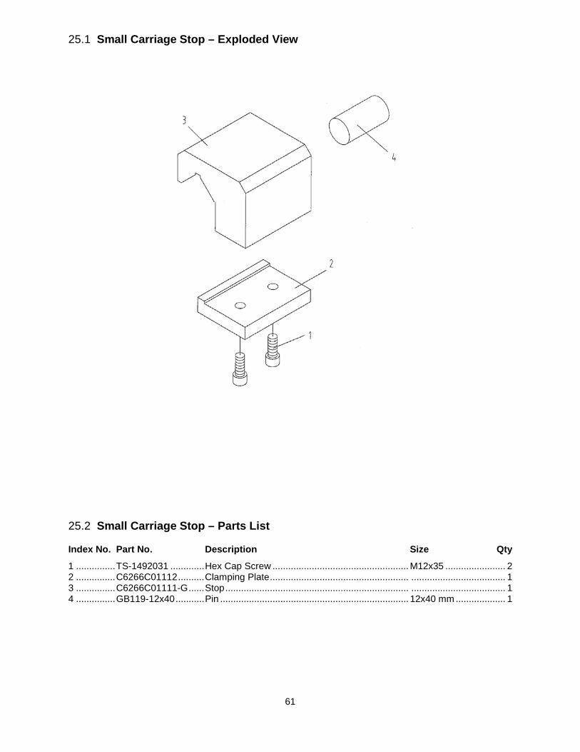
61
25.1 Small Carriage Stop – Exploded View
25.2 Small Carriage Stop – Parts List
Index No. Part No. Description Size Qty
1 ............... TS-1492031 ............. Hex Cap Screw .................................................... M12x35 ....................... 2 2 ............... C6266C01112 .......... Clamping Plate ..................................................... .................................... 1 3 ............... C6266C01111-G ...... Stop ...................................................................... .................................... 1 4 ............... GB119-12x40 ........... Pin ........................................................................ 12x40 mm ................... 1
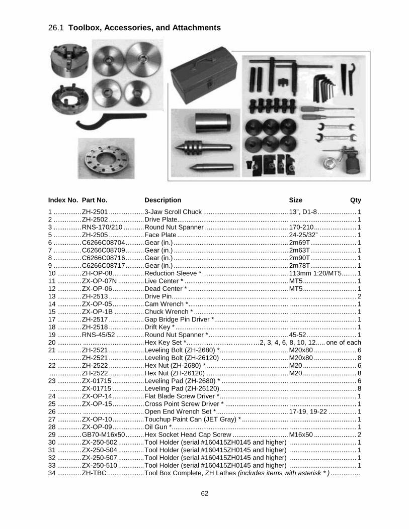
62
26.1 Toolbox, Accessories, and Attachments
Index No. Part No. Description Size Qty 1 ............... ZH-2501 ................... 3-Jaw Scroll Chuck .............................................. 13”, D1-8 ..................... 1 2 ............... ZH-2502 ................... Drive Plate............................................................ .................................... 1 3 ............... RNS-170/210 ........... Round Nut Spanner ............................................. 170-210 ....................... 1 5 ............... ZH-2505 ................... Face Plate ............................................................ 24-25/32” .................... 1 6 ............... C6266C08704 .......... Gear (in.) .............................................................. 2m69T ......................... 1 7 ............... C6266C08709 .......... Gear (in.) .............................................................. 2m63T ......................... 1 8 ............... C6266C08716 .......... Gear (in.) .............................................................. 2m90T ......................... 1 9 ............... C6266C08717 .......... Gear (in.) .............................................................. 2m78T ......................... 1 10 ............. ZH-OP-08 ................. Reduction Sleeve * .............................................. 113mm 1:20/MT5 ........ 1 11 ............. ZX-OP-07N .............. Live Center * ........................................................ MT5 ............................. 1 12 ............. ZX-OP-06 ................. Dead Center * ...................................................... MT5 ............................. 1 13 ............. ZH-2513 ................... Drive Pin ............................................................... .................................... 2 14 ............. ZX-OP-05 ................. Cam Wrench * ...................................................... .................................... 1 15 ............. ZX-OP-1B ................ Chuck Wrench * ................................................... .................................... 1 17 ............. ZH-2517 ................... Gap Bridge Pin Driver * ........................................ .................................... 1 18 ............. ZH-2518 ................... Drift Key * ............................................................. .................................... 1 19 ............. RNS-45/52 ............... Round Nut Spanner * ........................................... 45-52 ........................... 1 20 ............. ................................. Hex Key Set *……………………………2, 3, 4, 6, 8, 10, 12 ..... one of each 21 ............. ZH-2521 ................... Leveling Bolt (ZH-2680) * ..................................... M20x80 ....................... 6 ................. ZH-2521 ................... Leveling Bolt (ZH-26120) .................................... M20x80 ....................... 8 22 ............. ZH-2522 ................... Hex Nut (ZH-2680) * ............................................ M20 ............................. 6 ................. ZH-2522 ................... Hex Nut (ZH-26120) ............................................ M20 ............................. 8 23 ............. ZX-01715 ................. Leveling Pad (ZH-2680) * .................................... .................................... 6 ................. ZX-01715 ................. Leveling Pad (ZH-26120) ..................................... .................................... 8 24 ............. ZX-OP-14 ................. Flat Blade Screw Driver * ..................................... .................................... 1 25 ............. ZX-OP-15 ................. Cross Point Screw Driver * .................................. .................................... 1 26 ............. ................................. Open End Wrench Set * ....................................... 17-19, 19-22 ............... 1 27 ............. ZX-OP-10 ................. Touchup Paint Can (JET Gray) * ......................... .................................... 1 28 ............. ZX-OP-09 ................. Oil Gun * ............................................................... .................................... 1 29 ............. GB70-M16x50 .......... Hex Socket Head Cap Screw .............................. M16x50 ....................... 2 30 ............. ZX-250-502 .............. Tool Holder (serial #160415ZH0145 and higher) .................................... 1 31 ............. ZX-250-504 .............. Tool Holder (serial #160415ZH0145 and higher) .................................... 1 32 ............. ZX-250-507 .............. Tool Holder (serial #160415ZH0145 and higher) .................................... 1 33 ............. ZX-250-510 .............. Tool Holder (serial #160415ZH0145 and higher) .................................... 1 34 ............. ZH-TBC .................... Tool Box Complete, ZH Lathes (includes items with asterisk * ) ................
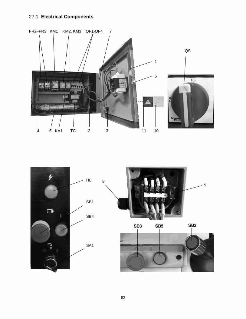
63
27.1 Electrical Components FR2–FR3 KM1 KM2, KM3 QF1-QF4 7
4 5 KA1 TC 2 3 11 10
1
QS
6
HL
SB1
SB4
SA1
89
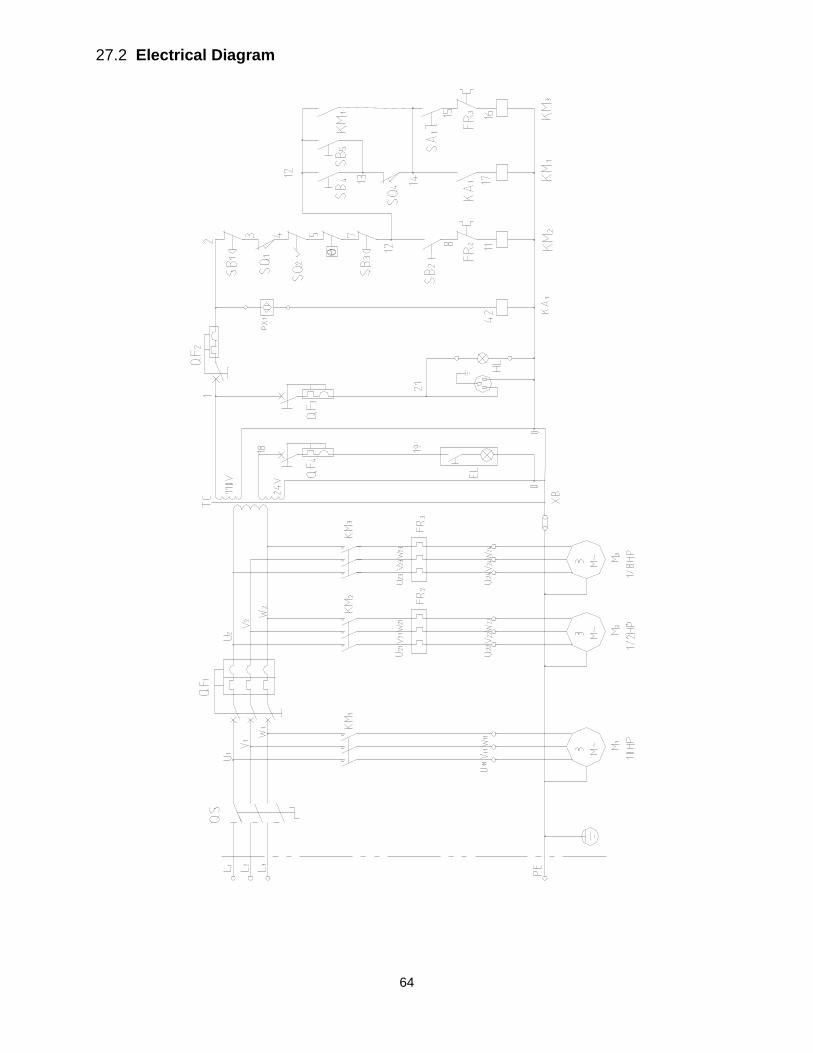
64
27.2 Electrical Diagram
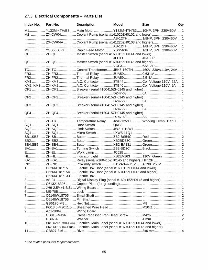
65
27.3 Electrical Components – Parts List
Index No. Part No. Description Model Size Qty M1......... ....... Y132M-4TH/B3 ....... Main Motor .................... Y132M-4TH/B3 ..... 10HP, 3PH, 230/460V ..... 1 M2 ............... ZX-CW04 ................ Coolant Pump (serial #141020ZH0102 and lower) ................................. ..................... ................................ ...................................... AB-12TH ............... 1/8HP, 3PH, 230/460V .... 1 ..................... ZX-CW04A ............. Coolant Pump (serial #141220ZH0103 and higher) ................................ ..................... ................................ ...................................... AB-12TH ............... 1/8HP, 3PH, 230/460V .... 1 M3 ................ YSS56BJ-G ............ Rapid Feed Motor ......... YSS5634 ............... 1/2HP, 3PH, 230/460V .... 1 QF ................ ZH-QF..................... Master Switch (serial #160315ZH0144 and lower) ................................. ..................... ................................ ...................................... JFD11 ................... 40A, 3P ............................ 1 QS ................ ZH-QS .................... Master Switch (serial #160415ZH0145 and higher) ................................ ..................... ................................ ...................................... VCF3 ..................... 63A, 3P ............................ 1 TC ................. ZH-TC ..................... Control Transformer ...... JBK5-160TH ......... 460V, 230V/110V, 24V .... 1 FR3 ............... ZH-FR3 ................... Thermal Relay .............. 3UA59 ................... 0.63-1A ............................ 1 FR2 ............... ZH-FR2 ................... Thermal Relay .............. 3UA59 ................... 2.5-4A .............................. 1 KM1 .............. ZX-KM3 .................. A.C. Contactor .............. 3TB44 ................... Coil Voltage 110V, 22A ... 1 KM2, KM3..... ZX-KM2 .................. A.C. Contactor .............. 3TB40 ................... Coil Voltage 110V, 9A ..... 2 QF1 .............. ZH-QF1................... Breaker (serial #160415ZH0145 and higher) .......................................... ..................... ................................ ...................................... DZ47-63 ................ 6A .................................... 1 QF2 .............. ZH-QF2................... Breaker (serial #160415ZH0145 and higher) .......................................... ..................... ................................ ...................................... DZ47-63 ................ 3A .................................... 1 QF3 .............. ZH-QF3................... Breaker (serial #160415ZH0145 and higher) .......................................... ..................... ................................ ...................................... DZ47-63 ................ 3A .................................... 1 QF4 .............. ZH-QF4................... Breaker (serial #160415ZH0145 and higher) .......................................... ..................... ................................ ...................................... DZ47-63 ................ 3A .................................... 1 θ ...................... ZH-TR ..................... Temperature Relay ....... JW6-125°C ........... Working Temp. 125°C ..... 1 SQ1 .............. ZH-SQ1 .................. Door Switch .................. QKS8 .................... ......................................... 1 SQ2 .............. ZH-SQ2 .................. Limit Switch ................... JW2-11H/W1 ........ ......................................... 1 SQ4 .............. ZH-SQ4 .................. Micro Switch ................. LXW5-11Q1 .......... ......................................... 1 SB1,SB3 ....... ZH-SB1 ................... Button............................ ZB2-BS54C........... Red .................................. 2 SB2 ............... ZH-SB2 ................... Button............................ XB2BD53C ........... Green ............................... 1 SB4,SB5 ....... ZH-SB4 ................... Button............................ XB2-EA131 ........... Green ............................... 2 SA1 ............... ZH-SA1 ................... Turning Switch .............. ZB2-BD2C ............ Black ................................ 1 EL ................. ZH-EL ..................... Work Lamp ................... JC52B ................... ......................................... 1 HL ................. ZH-HL ..................... Indicator Light ............... XB2EV163 ............ 110V, Green .................... 1 KA1 ............... ZH-KA1 ................... Relay (serial #160415ZH0145 and higher).. HH52P ............................. 1 PX1 ............... ZH-PX1 ................... Proximity switch ............ LJ12A3-4-J/EZ ...... AC90~250V ..................... 1 1 .................. C6266C18715 ........ Electric Box Door (serial #160315ZH0144 and lower) .......................... 1 ..................... C6266C18715A ...... Electric Box Door (serial #160415ZH0145 and higher) ......................... 1 2 ................... C6266C18713-G .... Electric Box ................... .............................. ......................................... 1 3 ................... AS-04...................... Digital Display Plug (serial #160415ZH0145 and higher) ...................... 1 4 ................... C613218306 ........... Copper Plate (for grounding) ....................... ......................................... 1 5 ................... JH9-2.5/4+1.5/31 .... Wiring Board ................. .............................. ......................................... 1 6 ................... MS-705 ................... Lock .............................. .............................. ......................................... 1 7 ................... C6140W18705 ....... Small Shaft ................... .............................. ......................................... 2 ..................... C6140W18706 ....... Pin Shaft ....................... .............................. ......................................... 2 ..................... GB6170-M8 ............ Hex Nut ......................... .............................. M8 .................................... 2 8 ................... PG13.5-M20x1.5 .... Sheathed Wire Head .... .............................. M20x1.5 ........................... 1 9 ................... AZ1-2004 ................ Wiring Board ................. .............................. ......................................... 1 ..................... GB818-M4x6 .......... Cross Recessed Pan Head Screw .............. M4x6 ................................ 2 ..................... GB97-4 ................... Washer.......................... .............................. 4 mm ................................ 2 10 ................. C6136ZK18304A (in) . Electrical Main Label (serial #160315ZH0144 and lower) ..................... 1 ..................... C6266C18304-11(in) . Electrical Main Label (serial #160415ZH0145 and higher) ................... 1 11 ................. GB827-3x6 ............. Rivet .............................. .............................. 3x6 mm ............................ 4 * See related parts lists for part numbers.
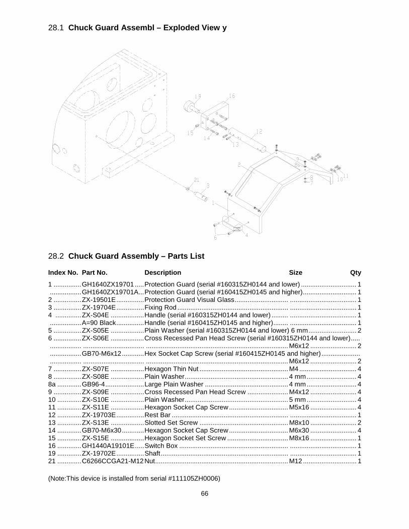
66
28.1 Chuck Guard Assembl – Exploded View y
28.2 Chuck Guard Assembly – Parts List
Index No. Part No. Description Size Qty
1 ............... GH1640ZX19701 ..... Protection Guard (serial #160315ZH0144 and lower) .............................. 1 ................. GH1640ZX19701A ... Protection Guard (serial #160415ZH0145 and higher) ............................. 1 2 ............... ZX-19501E ............... Protection Guard Visual Glass ............................. .................................... 1 3 ............... ZX-19704E ............... Fixing Rod ............................................................ .................................... 1 4 .............. ZX-S04E .................. Handle (serial #160315ZH0144 and lower) ......... .................................... 1 ................. A=90 Black ............... Handle (serial #160415ZH0145 and higher) ........ .................................... 1 5 ............... ZX-S05E .................. Plain Washer (serial #160315ZH0144 and lower) 6 mm .......................... 2 6 ............... ZX-S06E .................. Cross Recessed Pan Head Screw (serial #160315ZH0144 and lower) ..... ................. ................................. ............................................................................. M6x12 ......................... 2 ................. GB70-M6x12 ............ Hex Socket Cap Screw (serial #160415ZH0145 and higher) ..................... ................. ................................. ............................................................................. M6x12 ......................... 2 7 ............... ZX-S07E .................. Hexagon Thin Nut ................................................ M4 ............................... 4 8 ............... ZX-S08E .................. Plain Washer ........................................................ 4 mm ........................... 4 8a ............. GB96-4 ..................... Large Plain Washer ............................................. 4 mm ........................... 4 9 ............... ZX-S09E .................. Cross Recessed Pan Head Screw ...................... M4x12 ......................... 4 10 ............. ZX-S10E .................. Plain Washer ........................................................ 5 mm ........................... 4 11 ............. ZX-S11E .................. Hexagon Socket Cap Screw ................................ M5x16 ......................... 4 12 ............. ZX-19703E ............... Rest Bar ............................................................... .................................... 1 13 ............. ZX-S13E .................. Slotted Set Screw ................................................ M8x10 ......................... 2 14 ............. GB70-M6x30 ............ Hexagon Socket Cap Screw ................................ M6x30 ......................... 4 15 ............. ZX-S15E .................. Hexagon Socket Set Screw ................................. M8x16 ......................... 1 16 ............. GH1440A19101E ..... Switch Box ........................................................... .................................... 1 19 ............. ZX-19702E ............... Shaft ..................................................................... .................................... 1 21 ............. C6266CCGA21-M12 Nut ........................................................................ M12 ............................. 1 (Note:This device is installed from serial #111105ZH0006)
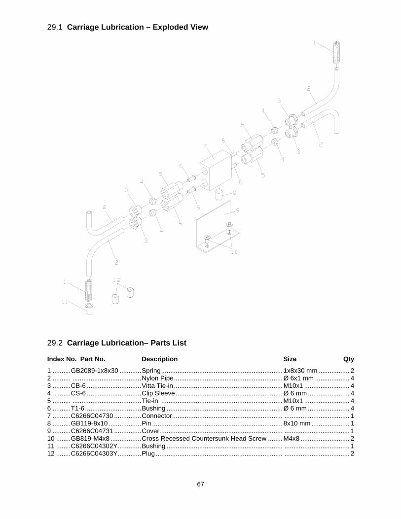
67
29.1 Carriage Lubrication – Exploded View
29.2 Carriage Lubrication– Parts List
Index No. Part No. Description Size Qty
1 .......... GB2089-1x8x30 ............ Spring ................................................................... 1x8x30 mm ................. 2 2 .......... ...................................... Nylon Pipe ............................................................ Ø 6x1 mm ................... 4 3 .......... CB-6 .............................. Vitta Tie-in ............................................................ M10x1 ......................... 4 4 ......... CS-6 .............................. Clip Sleeve ........................................................... Ø 6 mm ....................... 4 5 .......... ...................................... Tie-in ................................................................... M10x1 ......................... 4 6 .......... T1-6 ............................... Bushing ................................................................ Ø 6 mm ....................... 4 7 .......... C6266C04730 ............... Connector............................................................. .................................... 1 8 .......... GB119-8x10 .................. Pin ........................................................................ 8x10 mm ..................... 1 9 .......... C6266C04731 ............... Cover .................................................................... .................................... 1 10 ........ GB819-M4x8 ................. Cross Recessed Countersunk Head Screw ........ M4x8 ........................... 2 11 ........ C6266C04302Y ............. Bushing ................................................................ .................................... 1 12 ........ C6266C04303Y ............. Plug ...................................................................... .................................... 2

68
Ordering Replacement Parts To order parts or reach our service department, call 1-800-274-6848 Monday through Friday, 8:00 a.m. to 5:00 p.m. CST. Having the Model Number and Serial Number of your machine available when you call will allow us to serve you quickly and accurately.
Non-proprietary parts, such as fasteners, can be found at local hardware stores, or may be ordered from JET.
Some parts are shown for reference only, and may not be available individually.
427 New Sanford Road LaVergne, Tennessee 37086
Phone: 800-274-6848 www.jettools.com