installation manual - pollite · anemomete mast 180mm step 22 step 23 run the aluminium tape down...
TRANSCRIPT

INSTALLATION MANUAL
f r ang ib l e s t r uc tu res
Anemometer Mast10000mm (180mm)
ANEMOMETER MAST 180MM10
000m
m
400mm
400mm
180mm
300mm
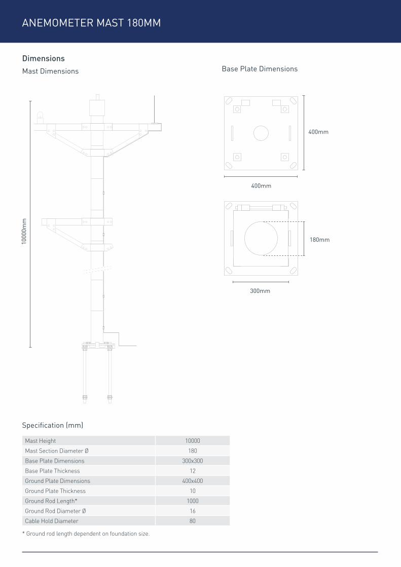
* Ground rod length dependent on foundation size.
Mast Height 10000
Mast Section Diameter Ø 180
Base Plate Dimensions 300x300
Base Plate Thickness 12
Ground Plate Dimensions 400x400
Ground Plate Thickness 10
Ground Rod Length* 1000
Ground Rod Diameter Ø 16
Cable Hold Diameter 80
Base Plate Dimensions
Specification (mm)
DimensionsMast Dimensions

ANEMOMETER MAST 180MM
A 1 x MastB 1 x Ground PlateC 1 x Ground Plate Template (Optional)D 1 x Hinge Bolt, Nut & WasherE 4 x Foundation Rods, Nuts & Square WashersF 4 x WashersG 4 x Full NutsH Cross Arm Assembly (As Required)I Upper Support Brackets (As Required)
J Lower Support Brackets (As Required)K 1 x GRP Plug (Optional)L 1 x Rubber GrommetM 4 x Bolts M20N 4 x Large WashersO 1 x Obstruction LightP 1 x Adjustable Spanner (Not Included)Q 1 x Utility Knife (Not Included)
Parts Checklist - Mast
C
I
N
D
J
O
F
K
P
E
G
L
Q
A B
H
M

ANEMOMETER MAST 180MM
A 1 x Air RodB 1 x Air Rod BracketC 2 x Air Rod Bracket Counter Suck Screws & WashersD 1 x 10m Aluminium TapeE 15 x Plastic ClipsF 15 x Anchor Nuts & ScrewsG 1 x In-Line Tape Connector
H 1 x Threaded CouplingI 1 x Copper RodJ 1 x 5m Copper TapeK 1 x Brass ClampL 1 x Earth BoxM 1 x Drill (Not Included)N 1 x Hammer (Not Included)
Parts Checklist - Lightning Protection
C
I
N
D
JF
K
E
G
L
A B
H
M

ANEMOMETER MAST 180MM
Step 3
Step 4
Level the ground plate using the nuts on the underside of the plate.
Once level screw one washer and one nut onto all four ground rods to secure the ground plate. Torque the nuts to 180Nm.
Step 5Mate the two half hinges of the mast base plate and the ground plate together, ensuring the holes are aligned.
Step 2Once set, remove the retaining nuts and template if used. Thread the cable through the central hole of the base plate and rest the ground plate onto the washers. Ensure the hinge is facing in the required direction.
Step 1At the base of each foundation rod, fit a nut, square washer and a nut.
Screw one nut and one washer onto each threaded foundation rod for distance ‘A’ as shown on the concrete foundation dimension.
Rest the ground plate (or template, if casting in advance of the masts) onto the washers ensuring the hinge is facing up, secure the plate in position with a retaining nut on each rod.
Place the foundation bolts in the concrete at the correct depth, ensuring there is a maximum gap of distance ‘B’ between the concrete and the ground plate, as shown on the diagram. This is to make it possible to adjust the mast vertically later. (To help maintain a gap, use wooden lats.)
a)
b)
c)
d)
B (30mm)
Nut / Square Washer / Nut
Concrete Foundation
A (60mm)

ANEMOMETER MAST 180MM
Step 7
Step 8
Once the base plate has been correctly secured to the ground plate, rest the mast horizontally and feed the cables up through the mast to the pre-drilled hole at the top.
To prevent ingress of water into the mast, slice the rubber grommet and thread it onto the cable. Secure the grommet into the wall of the mast.
Step 6Once the holes are aligned, slide through the hinge bolt, use a large hammer if required. Secure the hinge bolt with the washer and nut provided. Torque the nut to between 150-200Nm.
Step 10
Step 11
Wrap the upper support brackets around the top of the mast, directly below the top cap.
Align the two holes on the bracket with the two holes on the cross arm. Insert the two bolts and secure with the washers and nuts provided, repeat on both sides. Torque the nuts to between 15-20Nm.
Step 9Remove the bolts from the cross arm assembly.

ANEMOMETER MAST 180MM
Step 15
Step 14
Step 16
Screw the obstruction light directly onto the threaded bracket located on the cross arm. Position the light bracket and torque the nuts to between 10-20Nm. (For cabling of OBS light, see manufacturers installation guide.)
If supplementary cross arms are required, repeat the process above. If using a half cross arm, use the GRP blanks provided in between the two halves of the upper bracket and the two halves of the lower bracket. Torque the nuts to between 15-20Nm.
Remove the four countersunk screws that hold the two halves of the air rod saddle together. Align the holes of the lower half of the saddle with those on the air rod bracket located on the cross arm. Secure in place using the two countersunk screws, washers and nuts provided. Position the air rod bracket and torque the nut to between 10-20Nm.
Step 12Wrap the lower support brackets around the mast. Align the two holes on the lower bracket with the two holes on the support arm. Insert the two bolts and secure with the washers and nuts provided, repeat for both sides. Torque the nuts to between 15-20Nm.
Step 13Once the lower support arm bracket is correctly located, tighten the nuts on the upper support arm brackets. Torque the M8 nuts to between 10-15Nm and the M12 nut to between 15-20Nm.

ANEMOMETER MAST 180MM
Step 22
Step 23
Run the aluminium tape down the mast, secure the tape in place using the clips.
Approximately 2m from the base drill the mast using an 8mm drill bit, taking care not to damage internal cables. Insert an anchor nut and attach the in-line tape connector using the screw provided.
Step 19
Step 21
Step 20
Screw the air rod into the saddle, hand tighten to secure. The tape should run down the support arm and down the mast.(See image sequence 4 for routing of the tape.)
At 2m intervals drill the mast using an 8mm drill bit, taking care not to damage internal cables. Insert an anchor nut and attach the plastic clips onto the mast using the screws provided.
At this point, if required fit the sensing equipment. (See manufacturers installation guide.)
Step 18Insert the shaved tape into the groove in the lower section of the saddle. Place the top of the saddle onto the lower half and secure in place using the four counter suck screws.
Step 17Use a knife to shave approximately 50mm of insulation tape from the aluminium tape.

ANEMOMETER MAST 180MM
Step 29
Step 30
Find a suitable location for the earth pit. Dig a hole big enough to place in the earth box. Use a large hammer to drive the copper rod into the ground. Ensure the copper coupling is protruding out from the ground.
Run the tape along from the mast to the earth rod. Connect the tape to the copper earth rod with brass clamp. Cover the rod with the Earth box lid. (Before cutting excess tape, ensure there’s sufficient spare so the tape is not under tension when lowering.)
Step 27Bring the copper tape up to the mast, cut out a 10mm opening in the end of the tape to fit the in-line connector bolt. Remove the bolt from the bottom half of the in-line connector. Locate the copper tape and secure in place by re-fitting the bolt.
Step 28Attach the threaded coupling onto the copper rod and screw on the driving head.
Step 26Secure the mast base plate to the ground plate using the bolts and large washers. Torque the large M20 bolts to between 200-250Nm.
Step 25Hinge the mast up vertically until it meets the ground plate resting blocks.(Use lifting assistance.)
Step 24Shave approximately 50mm off the end of the aluminium tape. Cut a 10mm opening in the end of the tape to fit the in-line connector bolt.