the wanz guide to window installation · step p1 – preliminary check 8 step p2 – cut the...
TRANSCRIPT

The WANZ Guide to Window Installation
0800 397 263 [email protected] 1 November 2017 | Version 1.4
as described in E2/AS1 Amendment 7

The WANZ Guide to Window Installation
as described in
E2/AS1 Amendment 7
1 November 2017 Version 1.4
This guide also includes installation details for specific Altus NZ Ltd products: The Eurostacker®, Euroslider®, Foldback® Bifold, Top Hung Bifold and the CodeMark certified Smartfit® Window Technology.
Window Association of New Zealand Page 1

WANZ Guide to E2/AS1 Amd. 7 1 November 2017
Window Association of New Zealand Page 2
Ver 1.3 - 1 December 2014
The WANZ Technical Committee have reviewed E2/AS1 Amendment 6 and agree that the
erratum does not affect the content of this document.
Ver 1.4 - 1 November 2017
The WANZ Technical Committee have added details pertaining to the installation of full
height windows and doors pushed up to the soffit lining.
The WANZ Technical Committee have reviewed E2/AS1 Amendment 7 and agree that the
erratum does not affect the content of this document.

WANZ Guide to E2/AS1 Amd. 7 1 November 2017
Window Association of New Zealand Page 3
Contents
Overview Page 5
Objective Page 5
Scope Page 5
Opening Preparation Page 7
Step P1 – Preliminary Check 8
Step P2 – Cut the Underlay 9
Step P3 – Flexible Flashing Tape 10
Cavity Construction Page 11
Step C1 – Sill Support Bar 12
Step C1a – Sill Support – Full Height 16
Step C2 – Position the Unit 19
Step C2a – Position the Unit – Full Height 21
Step C3 – Fixing 23
Step C3a – Fixing – Full Height 24
Step C4 – Air Seal 25
Step C5 – Head Flashing 26
Supplementary Detail 1.1 – Full Height to Soffit 31
Supplementary Detail 1.2 – Part Height to Soffit 34
Components – Cavity Construction Page 37
Typical Details Page 39
Masonry Veneer 40
Stucco 42
Bevel Back Weatherboards 43
Rusticated Weatherboards 44
Fibre Cement Weatherboards 45
Horizontal Profiled Metal 46

WANZ Guide to E2/AS1 Amd. 7 1 November 2017
Window Association of New Zealand Page 4
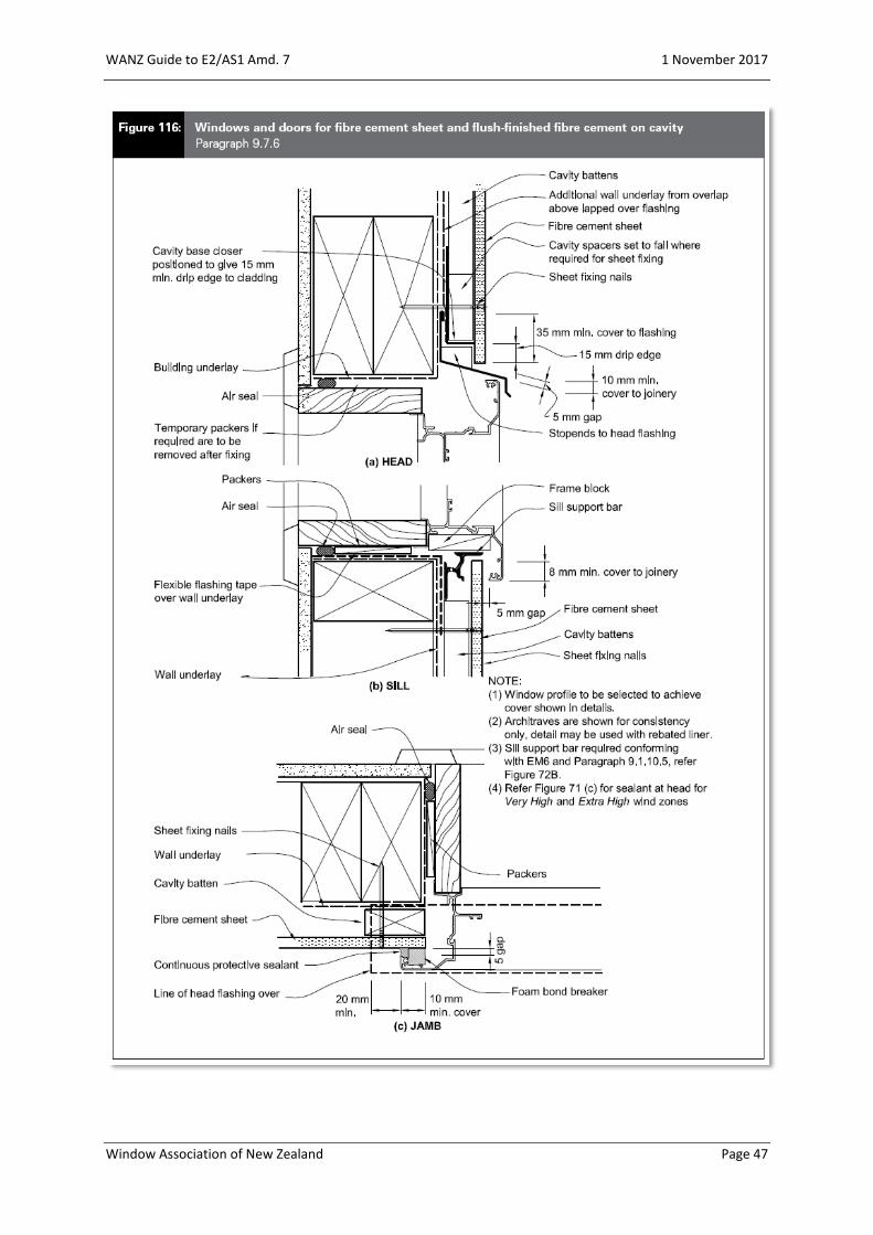
Fibre Cement Sheet 47
EIFS 48
Direct Fixed Claddings Page 49
Step D1 – Sill Tray Flashing 50
Step D2 – Position the Unit 54
Step D2a – Position the Unit – Full Height 55
Step D3 – Fixing 57
Step D3a – Fixing – Full Height 58
Step D4 – Air Seal 59
Step D5 – Head Flashing 60
Components – Direct Fix Claddings Page 65
Typical Details Page 67
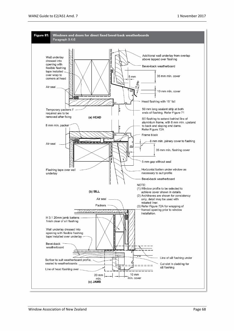
Bevel Back Weatherboards 68
Rusticated Weatherboards 69
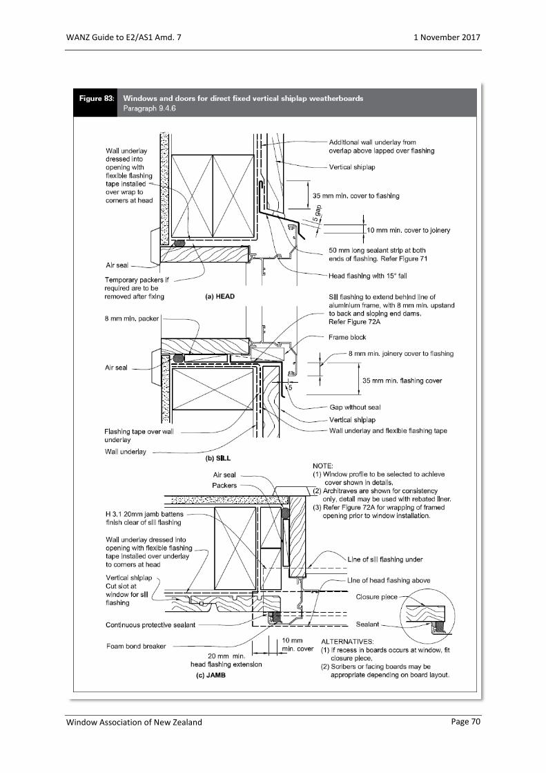
Vertical Shiplap Weatherboards 70
Board & Batten Weatherboards 71
Fibre Cement Weatherboards 72
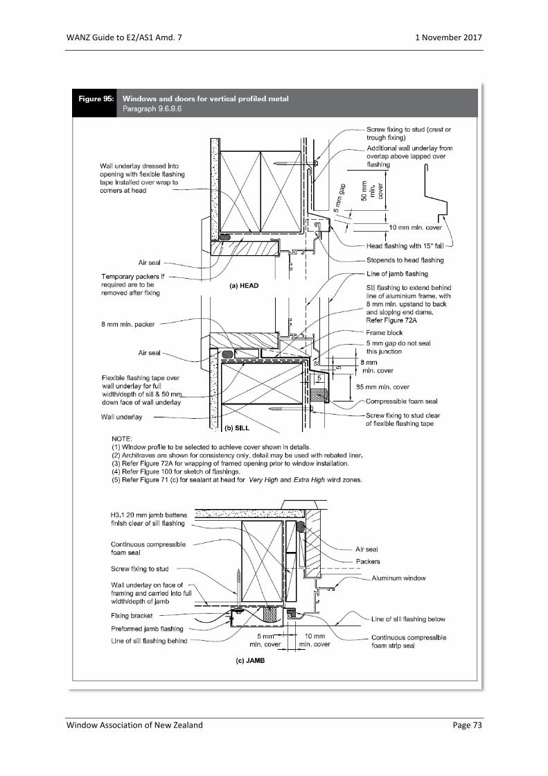
Vertical Profiled Metal 73
Fibre Cement Sheet 74
Altus NZ Ltd Specific Products Page 7576777879
Euroslider®Eurostacker®Foldback® BifoldTop Hung BifoldSmartfit® Window Technology 80

WANZ Guide to E2/AS1 Amd. 7 1 November 2017
Window Association of New Zealand Page 5
Overview
In 2009 the Department of Building & Housing invited WANZ to become a part of a working
group set up to assist in a technical review of E2/AS1. This was seen by WANZ as an
opportunity to address some of the confusion being experienced within the wider building
community through having two generic window installation systems available. The net
result, in terms of window installation, was E2/AS1 Amendment 5 which effectively merged
previous versions of the Acceptable Solution with WANZ WIS. There are some additional
items included in the document, which will be covered off as a part of this guide.
Objective
The objective of this document is an attempt to offer a better understanding of window and
door installation as described in E2/AS1 Amendment 7.
The details and drawings used within E2/AS1 to describe window and door installation are
two dimensional, cross sectional details which show a required end result. However, often a
more in-depth sequential approach might describe the process better to the end user. This
is what WANZ have attempted to do with this document by providing a step by step guide
to the details offered by this latest version of the Compliance Document E2/AS1.
Scope
Because this document is designed as a Guide to E2/AS1 Amendment 7, its scope is identical
to that listed in Section 1 (Pg. 25) of the Acceptable Solution.
E2/AS1 Amendment 7 contains the details for a number of generic solutions covering a
majority of the typical building situations encountered on building sites in New Zealand.
Obviously, there are many more situations that are not covered within its pages. The details
for these situations will need to be specifically designed to suit the conditions being
encountered. However, the principles expressed within the document, and in these pages,
will provide a good foundation for the development of specific details.

WANZ Guide to E2/AS1 Amd. 7 1 November 2017
Window Association of New Zealand Page 6
For the purpose of this guide it is assumed that the building designer has already worked
through the Risk Matrix and selected an appropriate cladding option, either Cavity
Construction or Direct Fixed cladding.
Note: There are a series of
size limitations as expressed
in Clause 9.1.10.1 Scope (Pg.
103)
Where your window or door
unit exceeds the limitations
set out within this clause,
please contact your window
supplier for alternative
details.

WANZ Guide to E2/AS1 Amd. 7 1 November 2017
Window Association of New Zealand Page 7
Opening Preparation
The preparation of the wall opening prior to the installation of the window or door is
essentially the same regardless of cladding option. The following offers a step by step guide
to the process.
WANZ Guide to E2/AS1 Amd. 7 1 November 2017
Window Association of New Zealand Page 8
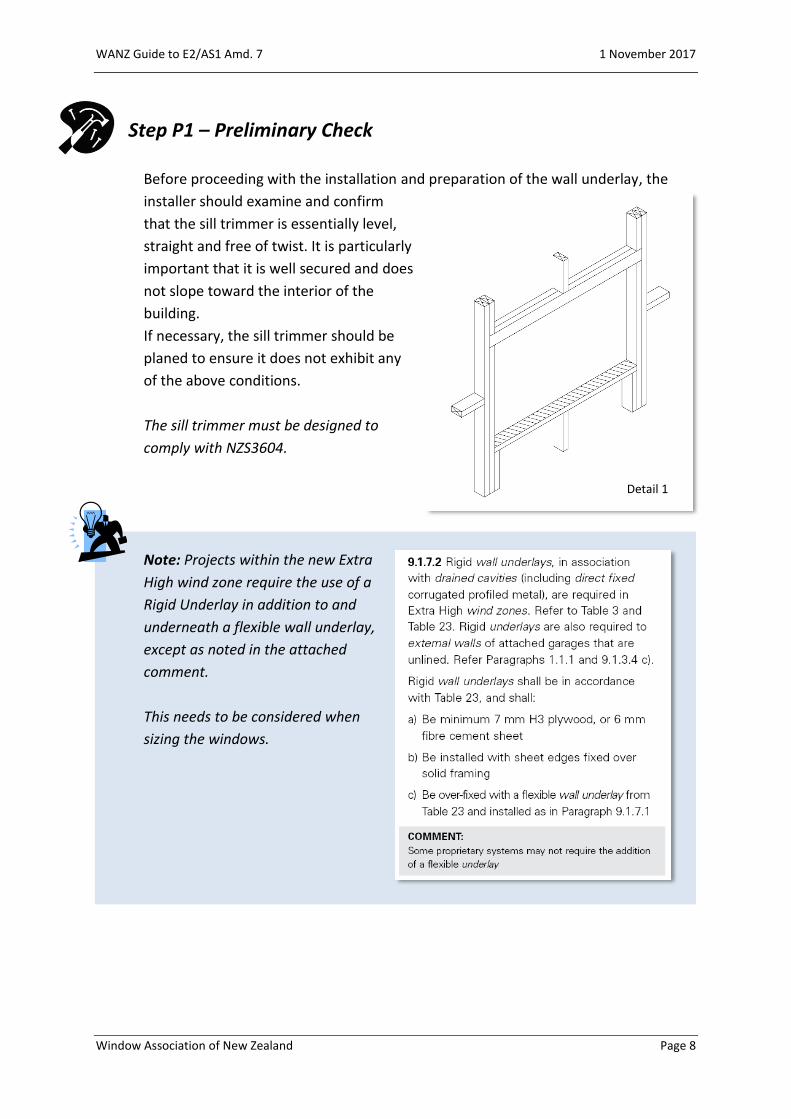
Step P1 – Preliminary Check
Before proceeding with the installation and preparation of the wall underlay, the
installer should examine and confirm
that the sill trimmer is essentially level,
straight and free of twist. It is particularly
important that it is well secured and does
not slope toward the interior of the
building.
If necessary, the sill trimmer should be
planed to ensure it does not exhibit any
of the above conditions.
The sill trimmer must be designed to
comply with NZS3604.
Note: Projects within the new Extra
High wind zone require the use of a
Rigid Underlay in addition to and
underneath a flexible wall underlay,
except as noted in the attached
comment.
This needs to be considered when
sizing the windows.
Detail 1

WANZ Guide to E2/AS1 Amd. 7 1 November 2017
Window Association of New Zealand Page 9
Step P2 – Cut the Underlay
Clause 9.1.5 a) describes the
application of a flexible wall
underlay.
To achieve this, follow these steps;
a. Cut the building underlay at 45o away from each corner.
b. Fold the flaps tightly into the opening and secure to the framing on all
sides.
c. Trim off excess underlay after fixing.
Note: Figures 72A & 72B do not show the inner extent of the flexible wall underlay.
The industry trend has been to cut this off at the inner corner of the framing as
wrapping around sometimes interferes with the internal linings. Ensure the underlay
is fixed tightly to the framework.
Detail 2

WANZ Guide to E2/AS1 Amd. 7 1 November 2017
Window Association of New Zealand Page 10
Step P3 – Flexible Flashing Tape
After ensuring the flashing
tape to be used meets the
criteria set out in Clause 9.1.5
b), follow these steps to satisfy
the clause;
a. Cut the flashing tape
for the sill at least
200mm wider than the
opening.
b. Fit the tape, as described in the manufacturers literature, with the inner edge
of the tape flush with the inside line of the framing, so that it extends a
minimum of 100mm up each jamb ensuring timber framing is covered.
c. Ensure the tape is securely
adhered to the underlay on all
surfaces and fits tightly into
each of the corners.
d. Cut two more pieces of tape at
least 200mm long and fit into
each of the upper corners as
described above ensuring
timber framing is covered.
Note: Ensure all exposed timber is covered, particularly in the corners. This may
mean the tape has to extend further than nominated.
Detail 3

WANZ Guide to E2/AS1 Amd. 7 1 November 2017
Window Association of New Zealand Page 11
Cavity Construction
Clause 9.1.10.2 c) & d) describes the basics of window installation for wall claddings over a
cavity.
Note: The use of a sill tray with cavity construction should be avoided. Its use will
impact on the airflow into the cavity around the window and therefore its ability to
pressure equalise. If a sill tray is
desired, then a Direct Fix type
solution for the window
installation must be created.

WANZ Guide to E2/AS1 Amd. 7 1 November 2017
Window Association of New Zealand Page 12
Step C1 – Sill Support Bar
Clause 9.1.10.5 b) v) describes the requirements of the Sill Support bar in terms of
compliance with E2/AS1. There are some important points to note;
a. Support is required on all
window and door units with a
trim opening over 600mm
wide,
b. The sill support bar must
comply with EM6, E2/VM1 &
B2/AS1,
c. Must be installed prior to the window or door unit.
d. The bar must be fitted in a manner that does not trap water on the sill
trimmer
The comment following Clause 9.1.10.5 b) v) makes reference to ensuring the
support bar is appropriate for the
application for which it is being
used. The EM6 test will allow the
calculation of an acceptable
weight limit for the support
mechanism being used and the
size and frequency of the fixings
required to achieve the support.
Clause 9.1.10.5 c) also makes this note
regarding the design of the sill support
bars.
Note: Selection of the appropriate sill support bar is important. Please refer below
for a guide to the options offered by WANZ members.

WANZ Guide to E2/AS1 Amd. 7 1 November 2017
Window Association of New Zealand Page 13
Figure 72B shows the general arrangement of the sill for a window installed into wall
claddings, over a cavity.
Note: Figure 72B indicates that the sill support bar may be up to 100mm short of the
trim opening at either end. It is recommended that the bar is installed to the full
width of the opening to ensure it picks up the window or door frame support blocks.
However, in some cases the use of non-proprietary corner soakers may require
shortening of the bar.

WANZ Guide to E2/AS1 Amd. 7 1 November 2017
Window Association of New Zealand Page 14
The WANZ sill support bars, as described on the Components page (Page 37) and
below, offer not only support to
the window or door unit, but also
drainage and ventilation of the
trim cavity. The WANZ bars have
been tested to EM6 and have
demonstrated compliance with
E2/VM1. In order to comply with
these documents, they must be
used in a continuous length
across the trim opening.
a. The sill support bar is positioned below the opening, and set so that the
upper edge sits a minimum of 5mm above the sill trimmer
The WANZ sill support bar is supplied with
locator blocks which are a quick and easy
method of setting the bar in the correct
position.
The locator blocks are designed to be re-used
but can remain if desired.
b. After fitting a locator block at each end
of the bar, position it into the trim
opening. Using a level find the high end
of the bar and fix the bar in place. Now
adjust the other end of the bar to level
and fix this end.
Detail 4
Detail 6
Detail 5

WANZ Guide to E2/AS1 Amd. 7 1 November 2017
Window Association of New Zealand Page 15
Note: The WANZ sill support bars, as described on the Components page
(Page 37) are designed to fit a
number of different claddings and
circumstances. Selection of the
correct bar, and its installation, is
important. Please refer to the
following to assist in the selection.
Fixing Options;
i. The generic fixing method into timber is 10g x 50mm stainless steel screws,
positioned at each end of the bar and at a maximum of 300mm centres
between.
ii. When fixing to concrete, the Heavy-Duty bars must be used. The same screws
and fixing centres, as noted above, apply but the screws would be driven into
nylon plugs or similar.
iii. For concrete the screws may be substituted for 6mm masonry anchors, at the
same centres. However, in order to achieve the required edge clearance that
these fasteners require, the Heavy-Duty bar must be re-drilled to suit.
WANZ Guide to E2/AS1 Amd. 7 1 November 2017
Window Association of New Zealand Page 16
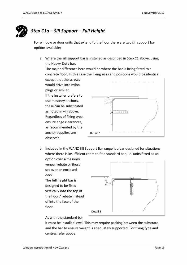
Step C1a – Sill Support – Full Height
For window or door units that extend to the floor there are two sill support bar
options available;
a. Where the sill support bar is installed as described in Step C1 above, using
the Heavy-Duty bar.
The major difference here would be where the bar is being fitted to a
concrete floor. In this case the fixing sizes and positions would be identical
except that the screws
would drive into nylon
plugs or similar.
If the installer prefers to
use masonry anchors,
these can be substituted
as noted in vii) above.
Regardless of fixing type,
ensure edge clearances,
as recommended by the
anchor supplier, are
observed.
b. Included in the WANZ Sill Support Bar range is a bar designed for situations
where there is insufficient room to fit a standard bar, i.e. units fitted as an
option over a masonry
veneer rebate or those
set over an enclosed
deck.
The full height bar is
designed to be fixed
vertically into the top of
the floor / rebate instead
of into the face of the
floor.
As with the standard bar
it must be installed level. This may require packing between the substrate
and the bar to ensure weight is adequately supported. For fixing type and
centres refer above.
Detail 8
Detail 7

WANZ Guide to E2/AS1 Amd. 7 1 November 2017
Window Association of New Zealand Page 17
Note: Fixing holes into concrete should be pre-filled with sealant prior to the
installation of the fixing as noted in Figure 17A.
WANZ Guide to E2/AS1 Amd. 7 1 November 2017
Window Association of New Zealand Page 18
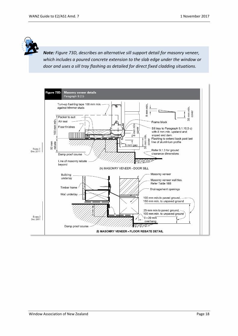
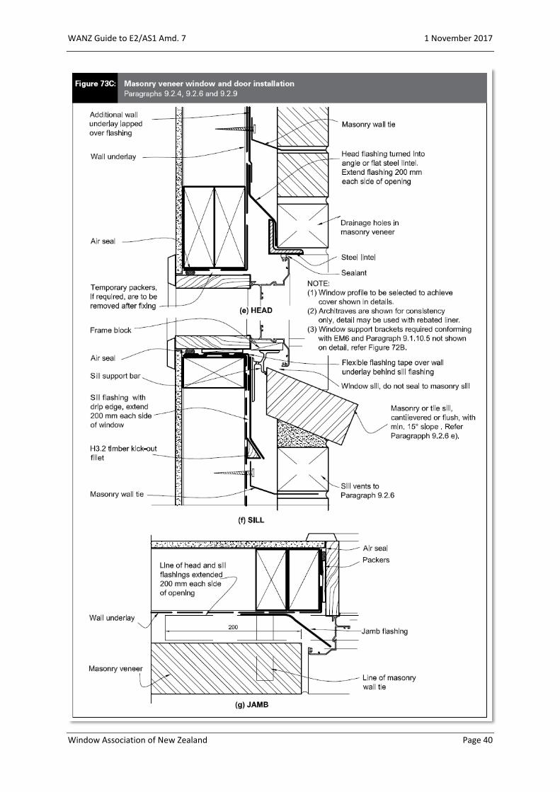
Note: Figure 73D, describes an alternative sill support detail for masonry veneer,
which includes a poured concrete extension to the slab edge under the window or
door and uses a sill tray flashing as detailed for direct fixed cladding situations.

WANZ Guide to E2/AS1 Amd. 7 1 November 2017
Window Association of New Zealand Page 19
Step C2 – Position the Unit
a. Before positioning the window or door unit into the opening ensure that,
where applicable, that the sill
corners have been fitted with
corner soaker as described in
Clause 9.1.10.5 c).
Check with your window
manufacturer regarding the
types of corner soaker used
with their systems and that
they are indeed applicable.
b. Ensure the unit is positioned so that;
i) The unit is positioned 5mm forward of the exterior cladding line, as
described in Clause 9.1.10.2 d),
ii) The interior linings finish in the correct positions,
iii) The unit is sitting
correctly on the sill
support bar,
Detail 9

WANZ Guide to E2/AS1 Amd. 7 1 November 2017
Window Association of New Zealand Page 20
iv) Once the installation has been completed, check that the required cover
over the exterior
cladding as described
in Clause 9.1.10, has
been achieved.
Note: Traditionally a nominal clearance of 5mm is detailed between the window
jamb liner and the framed opening. The purpose of this is i) to allow space for the
application of an air seal and ii) to avoid water being drawn into or being held within
the opening due to capillary action.
The industry now typically calls for an installation tolerance of 15mm (7.5mm each
side) on the framed opening, to allow for flashing tapes etc.

WANZ Guide to E2/AS1 Amd. 7 1 November 2017
Window Association of New Zealand Page 21
Step C2a – Position the Unit – Full Height
Figure 17C, describes the sill details for full height window and door units for
cavity construction. The positioning of the unit is essentially the same as
described in Step C2 above.
Note: Ensure the correct sill support bar is selected for these details, as described on
Pages 15 & 16, so that fixings are positioned appropriately.

WANZ Guide to E2/AS1 Amd. 7 1 November 2017
Window Association of New Zealand Page 22
Note: Some find the on-floor details described in Figure 17C to be undesirable. If so
then a rebated sill detail will need to be designed for the situation. In this case the
rebate becomes the threshold level, i.e. the floor level inside of the window or door
is irrelevant to the Acceptable Solution.
Rebated Timber Floor
Rebated Concrete Floor
Detail 11
Detail 10
WANZ Guide to E2/AS1 Amd. 7 1 November 2017
Window Association of New Zealand Page 23
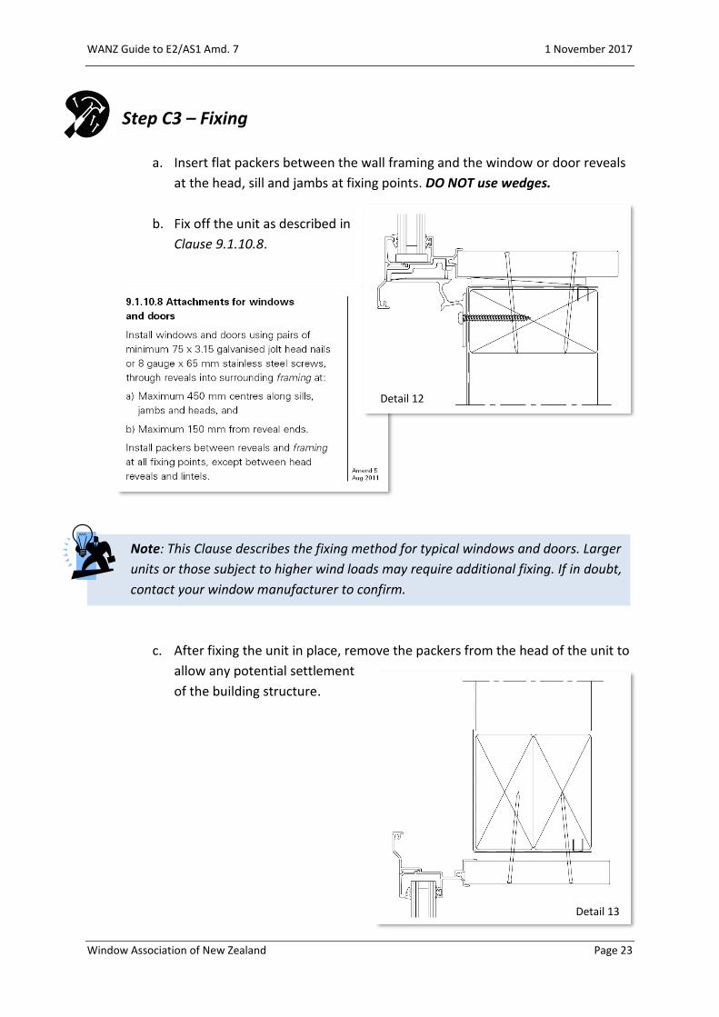
Step C3 – Fixing
a. Insert flat packers between the wall framing and the window or door reveals
at the head, sill and jambs at fixing points. DO NOT use wedges.
b. Fix off the unit as described in
Clause 9.1.10.8.
Note: This Clause describes the fixing method for typical windows and doors. Larger
units or those subject to higher wind loads may require additional fixing. If in doubt,
contact your window manufacturer to confirm.
c. After fixing the unit in place, remove the packers from the head of the unit to
allow any potential settlement
of the building structure.
Detail 12
Detail 13

WANZ Guide to E2/AS1 Amd. 7 1 November 2017
Window Association of New Zealand Page 24
Step C3a – Fixing – Full Height
For full height units fixed to concrete floors replace the nail fixings with 8g x
65mm screws driven into nylon plugs or similar.
If the installer prefers
to use masonry
anchors, these can be
substituted as noted
on Page 15.
Regardless of fixing
type, ensure edge
clearances, as
recommended by the
anchor supplier, are
observed.
Note: Fixing holes into concrete should be pre-filled with sealant prior to the
installation of the fixing as noted in Figure 17A (Page 17).
For timber floors, ensure the screw fixing is positioned a minimum of 20mm
from the edge of the
joist. This may
require re-drilling of
the sill support bar.
Detail 14
Detail 15
Detail 14

WANZ Guide to E2/AS1 Amd. 7 1 November 2017
Window Association of New Zealand Page 25
Step C4 – Air Seal
The Air Seal is designed to hold pressure in the trim cavity to enable pressure
equalisation to occur. Typically, the Air Seal is a low expansion polyurethane foam
installed over a PEF backing rod, as
described in Clause 9.1.6.
The detail drawings contained
within E2/AS1 show the air seal as a
single entity. Please note Clause
9.1.6 b).
Note: Clause 9.1.6 makes this
comment regarding air seals.
Detail 16
WANZ Guide to E2/AS1 Amd. 7 1 November 2017
Window Association of New Zealand Page 26
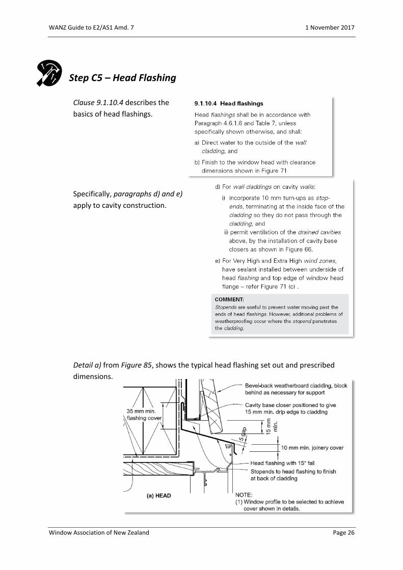
Step C5 – Head Flashing
Clause 9.1.10.4 describes the
basics of head flashings.
Specifically, paragraphs d) and e)
apply to cavity construction.
Detail a) from Figure 85, shows the typical head flashing set out and prescribed
dimensions.

WANZ Guide to E2/AS1 Amd. 7 1 November 2017
Window Association of New Zealand Page 27
Table 7 describes the upstand cover required by window head flashings.
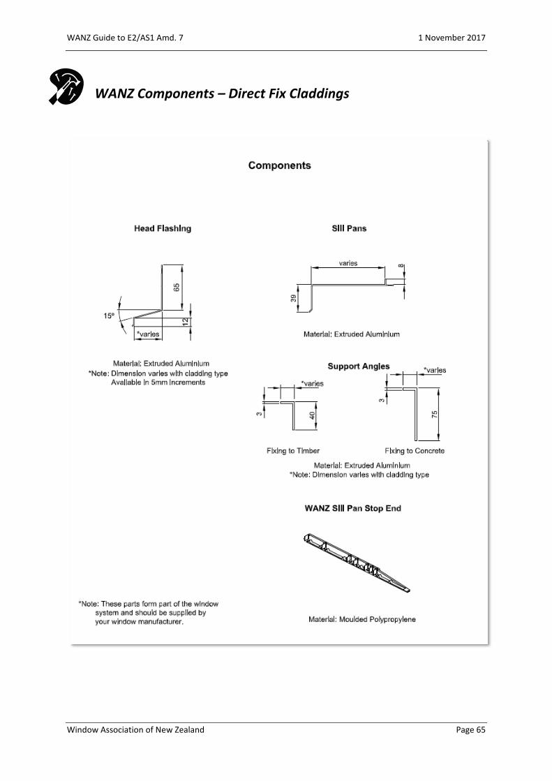
The most common form of window or door head flashing is the extruded aluminium
version, chosen primarily because of its consistent dimension and ease of
installation. Those supplied by
WANZ members are available to
suit a wide range of claddings.
These extruded flashings are
designed to provide a nominal
5mm gap between the back of the
flashing and the face of the
window.
With Amendment 7 to E2/AS1 the
design of the vertical upstand of
the flashing has been increased to
65mm to comply with Table 7 and
Clause 4.5.1 2).
However, these do not comply for
use in an Extra High Wind Zone,
unless they are provided with a
hook or hem to the upper edge of
the flashing.

WANZ Guide to E2/AS1 Amd. 7 1 November 2017
Window Association of New Zealand Page 28
Note: E2/AS1 Amendment 7 does not
prescribe the offset of the head flashing
from the face of the window flange. As
noted above WANZ members offer head
flashings designed to provide a nominal
5mm gap between the flashing and the
window is achieved, similar to that
shown below the cladding. The gap
helps to avoid capillary action drawing
water over the head of the window.
It is industry standard to extend the length of the head flashing 20mm past each side
of the window, i.e. window width +40mm.
In cases where jamb
scribers are used, these
are considered as a part
of the window width and
therefore the +40mm is
added to the overall
scriber dimension.
This is described in each of the window details shown within E2/AS1 Amendment 7.
Because of the difficulty in folding
extruded aluminium head flashings, the
stop ends, described in
Clause 9.1.10.4 d) i), can be supplied as
an applied injection moulded plastic
item which is fitted on site.
Detail 17
WANZ Guide to E2/AS1 Amd. 7 1 November 2017
Window Association of New Zealand Page 29
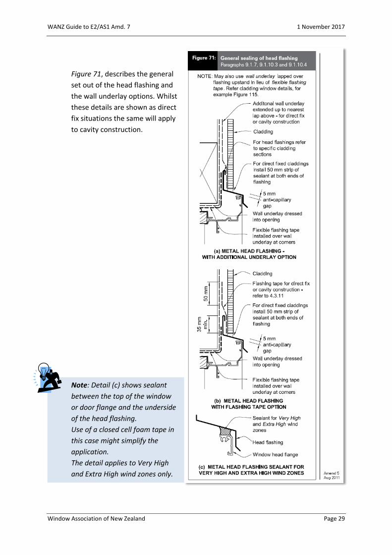
Figure 71, describes the general
set out of the head flashing and
the wall underlay options. Whilst
these details are shown as direct
fix situations the same will apply
to cavity construction.
Note: Detail (c) shows sealant
between the top of the window
or door flange and the underside
of the head flashing.
Use of a closed cell foam tape in
this case might simplify the
application.
The detail applies to Very High
and Extra High wind zones only.
WANZ Guide to E2/AS1 Amd. 7 1 November 2017
Window Association of New Zealand Page 30
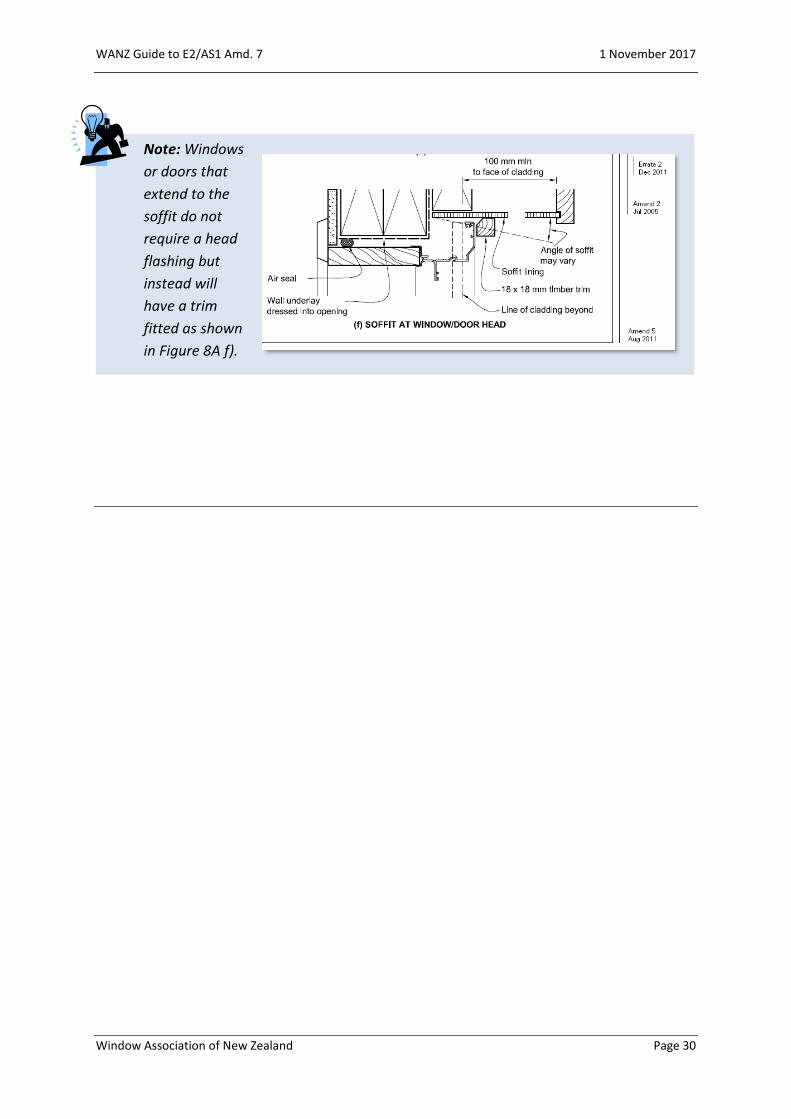
Note: Windows
or doors that
extend to the
soffit do not
require a head
flashing but
instead will
have a trim
fitted as shown
in Figure 8A f).
WANZ Guide to E2/AS1 Amd. 7 1 November 2017
Window Association of New Zealand Page 31
Supplementary Detail 1
In some instances, where a window or door unit is to finish against the soffit of
the building, then the Steps described in the preceding pages can be difficult to
achieve. The following modifications to these Steps could be made to ease the
installation process…
Detail 1.1 – Full Height to Soffit
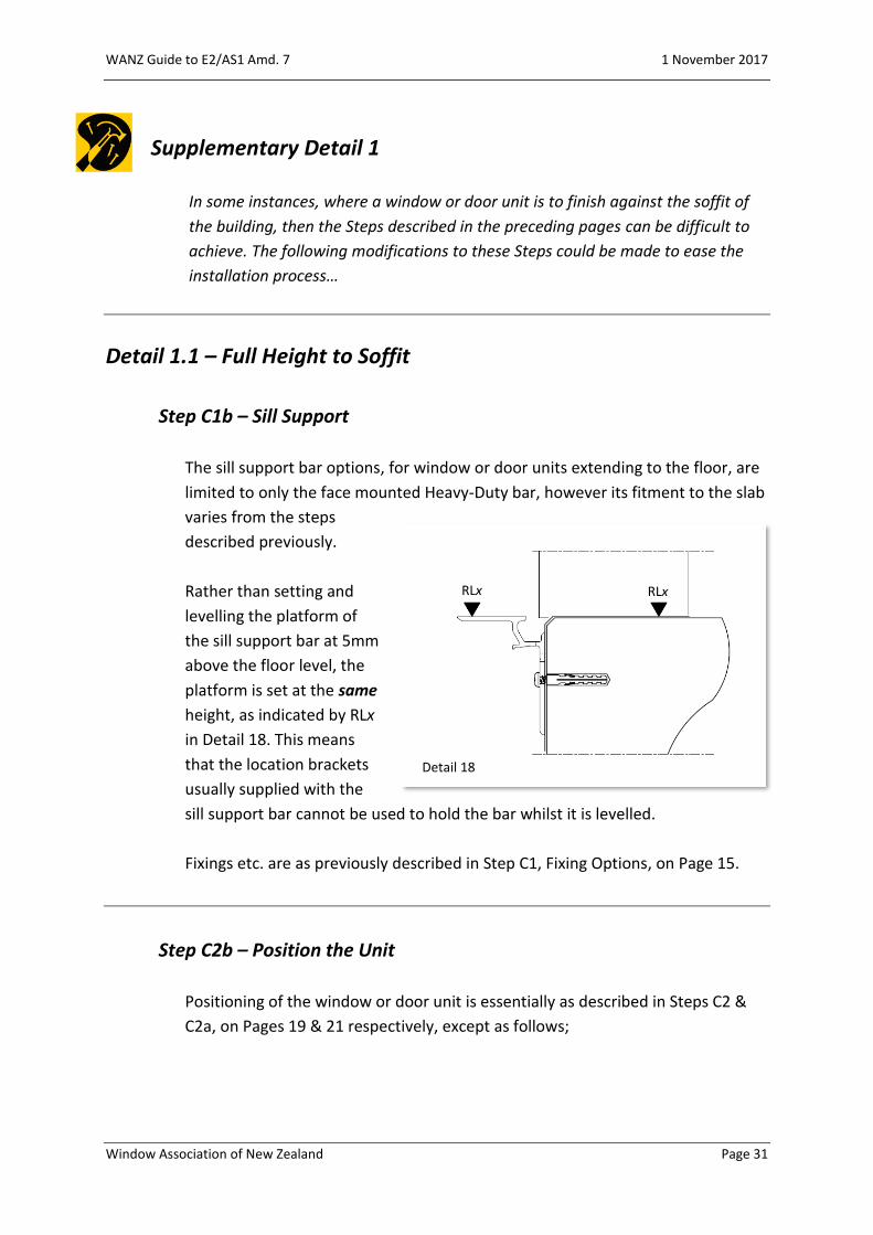
Step C1b – Sill Support
The sill support bar options, for window or door units extending to the floor, are
limited to only the face mounted Heavy-Duty bar, however its fitment to the slab
varies from the steps
described previously.
Rather than setting and
levelling the platform of
the sill support bar at 5mm
above the floor level, the
platform is set at the same
height, as indicated by RLx
in Detail 18. This means
that the location brackets
usually supplied with the
sill support bar cannot be used to hold the bar whilst it is levelled.
Fixings etc. are as previously described in Step C1, Fixing Options, on Page 15.
Step C2b – Position the Unit
Positioning of the window or door unit is essentially as described in Steps C2 &
C2a, on Pages 19 & 21 respectively, except as follows;
Detail 18
RLx RLx
WANZ Guide to E2/AS1 Amd. 7 1 November 2017
Window Association of New Zealand Page 32
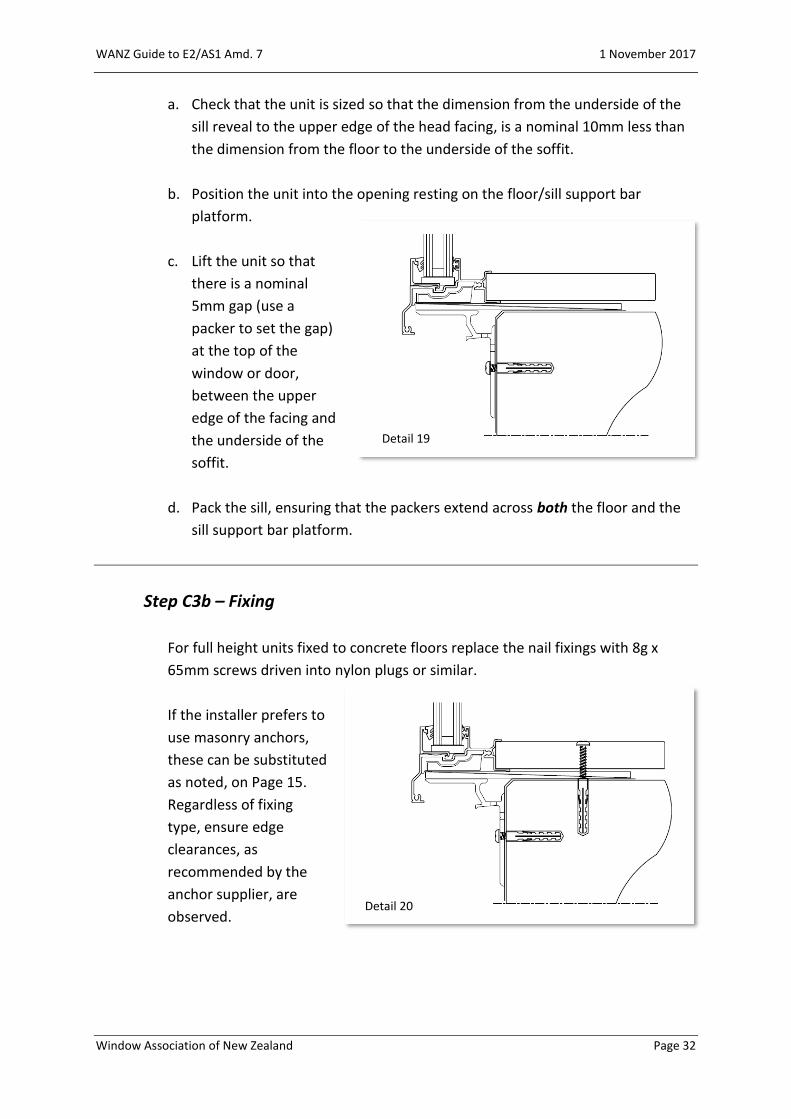
a. Check that the unit is sized so that the dimension from the underside of the
sill reveal to the upper edge of the head facing, is a nominal 10mm less than
the dimension from the floor to the underside of the soffit.
b. Position the unit into the opening resting on the floor/sill support bar
platform.
c. Lift the unit so that
there is a nominal
5mm gap (use a
packer to set the gap)
at the top of the
window or door,
between the upper
edge of the facing and
the underside of the
soffit.
d. Pack the sill, ensuring that the packers extend across both the floor and the
sill support bar platform.
Step C3b – Fixing
For full height units fixed to concrete floors replace the nail fixings with 8g x
65mm screws driven into nylon plugs or similar.
If the installer prefers to
use masonry anchors,
these can be substituted
as noted, on Page 15.
Regardless of fixing
type, ensure edge
clearances, as
recommended by the
anchor supplier, are
observed.
Detail 19
Detail 20

WANZ Guide to E2/AS1 Amd. 7 1 November 2017
Window Association of New Zealand Page 33
Step C4 – Air Seal
Apply the Air Seal as described in Step C4 on Page 25.
Step C5b – Head to Soffit
After ensuring all surfaces are clean (and primed where necessary), seal the gap
between the window
or door facing and the
soffit with a good
quality MS sealant.
Step C5, from Page 26,
describes the design
and installation of the
head flashing for a
window or door unit.
The primary function
of any head flashing is
to deflect any water
falling or running from
above away from a
potential entry point,
at the head of the unit. This is the first D (deflection) of the weathertightness
principles.
Note: In this case, where there is no falling/running water, and because of the
impracticality of fitting a head flashing in this environment, it is the seal that
protects the head from water ingress. This is described in Figure 8A f) of the
Acceptable Solution.
Before proceeding, the building designer must satisfy themselves that the detail
is robust enough to satisfy the conditions specific to their project.
Detail 21

WANZ Guide to E2/AS1 Amd. 7 1 November 2017
Window Association of New Zealand Page 34
Detail 1.2 – Part Height to Soffit
Step C1c – Sill Support
The sill support for window units sitting on a sill trimmer and extending to the
soffit varies from the steps
described previously.
Rather than setting and
levelling the platform of the
sill support bar at 5mm
above the sill trimmer, the
platform is set at the same
height, as indicated by RLx in
Detail 22. This means that
the location brackets usually
supplied with the sill
support bar cannot be used to hold
the bar whilst it is levelled.
Fixings etc. are as previously
described in Step C1, Fixing Options,
on Page 15.
Step C2c – Position the Unit
Positioning of the window unit is essentially as described in Steps C2 on Page 19,
except as follows;
a. Check that the unit is sized so that the dimension from the underside of the
sill reveal to the upper edge of the head facing, is a nominal 10mm less than
the dimension from the floor to the underside of the soffit.
Detail 22
RLx RLx
Detail 23
WANZ Guide to E2/AS1 Amd. 7 1 November 2017
Window Association of New Zealand Page 35
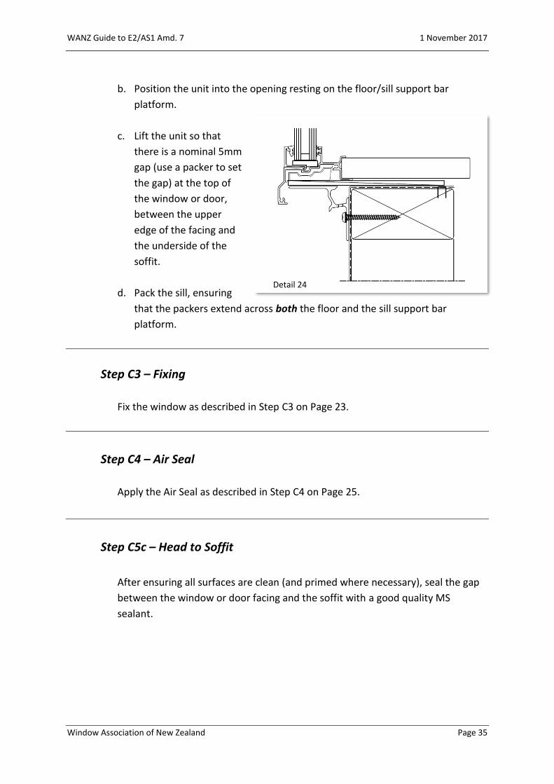
b. Position the unit into the opening resting on the floor/sill support bar
platform.
c. Lift the unit so that
there is a nominal 5mm
gap (use a packer to set
the gap) at the top of
the window or door,
between the upper
edge of the facing and
the underside of the
soffit.
d. Pack the sill, ensuring
that the packers extend across both the floor and the sill support bar
platform.
Step C3 – Fixing
Fix the window as described in Step C3 on Page 23.
Step C4 – Air Seal
Apply the Air Seal as described in Step C4 on Page 25.
Step C5c – Head to Soffit
After ensuring all surfaces are clean (and primed where necessary), seal the gap
between the window or door facing and the soffit with a good quality MS
sealant.
Detail 24

WANZ Guide to E2/AS1 Amd. 7 1 November 2017
Window Association of New Zealand Page 36
Step C5, from Page 26, describes the design and installation of the head flashing
for a window or door
unit. The primary
function of any head
flashing is to deflect
any water falling or
running from above
away from a potential
entry point, at the head
of the unit. This is the
first D (deflection) of
the weathertightness
principles.
Note: In this case, where there is no falling/running water, and because of the
impracticality of fitting a head flashing in this environment, it is the seal that
protects the head from water ingress. This is described in Figure 8A f) of the
Acceptable Solution.
Before proceeding, the building designer must satisfy themselves that the detail
is robust enough to satisfy the conditions specific to their project.
Detail 25

WANZ Guide to E2/AS1 Amd. 7 1 November 2017
Window Association of New Zealand Page 37
WANZ Components – Cavity Construction

WANZ Guide to E2/AS1 Amd. 7 1 November 2017
Window Association of New Zealand Page 38

WANZ Guide to E2/AS1 Amd. 7 1 November 2017
Window Association of New Zealand Page 39
Cavity Construction
Typical Details
WANZ Guide to E2/AS1 Amd. 7 1 November 2017
Window Association of New Zealand Page 40

WANZ Guide to E2/AS1 Amd. 7 1 November 2017
Window Association of New Zealand Page 41

WANZ Guide to E2/AS1 Amd. 7 1 November 2017
Window Association of New Zealand Page 42

WANZ Guide to E2/AS1 Amd. 7 1 November 2017
Window Association of New Zealand Page 43

WANZ Guide to E2/AS1 Amd. 7 1 November 2017
Window Association of New Zealand Page 44

WANZ Guide to E2/AS1 Amd. 7 1 November 2017
Window Association of New Zealand Page 45
WANZ Guide to E2/AS1 Amd. 7 1 November 2017
Window Association of New Zealand Page 46
WANZ Guide to E2/AS1 Amd. 7 1 November 2017
Window Association of New Zealand Page 47

WANZ Guide to E2/AS1 Amd. 7 1 November 2017
Window Association of New Zealand Page 48

WANZ Guide to E2/AS1 Amd. 7 1 November 2017
Window Association of New Zealand Page 49
Direct Fix Claddings
Clause 9.1.10.2 describes the basics of window installation for direct fixed wall
claddings.
WANZ Guide to E2/AS1 Amd. 7 1 November 2017
Window Association of New Zealand Page 50
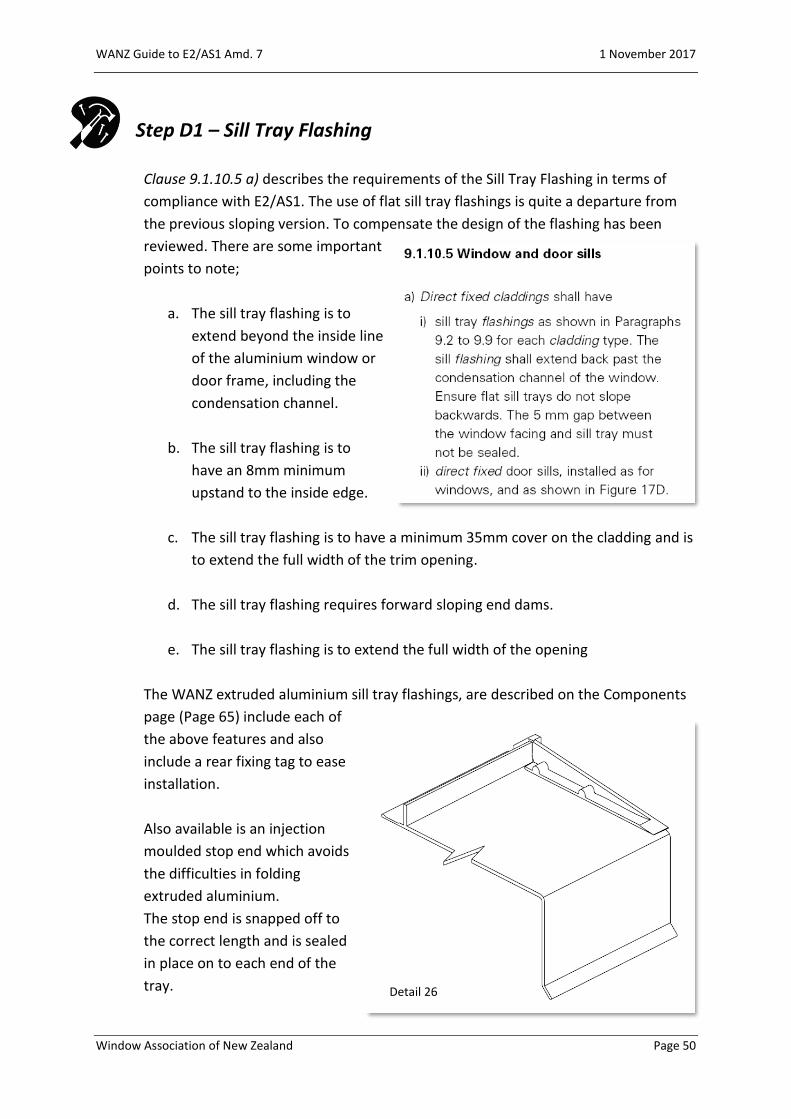
Step D1 – Sill Tray Flashing
Clause 9.1.10.5 a) describes the requirements of the Sill Tray Flashing in terms of
compliance with E2/AS1. The use of flat sill tray flashings is quite a departure from
the previous sloping version. To compensate the design of the flashing has been
reviewed. There are some important
points to note;
a. The sill tray flashing is to
extend beyond the inside line
of the aluminium window or
door frame, including the
condensation channel.
b. The sill tray flashing is to
have an 8mm minimum
upstand to the inside edge.
c. The sill tray flashing is to have a minimum 35mm cover on the cladding and is
to extend the full width of the trim opening.
d. The sill tray flashing requires forward sloping end dams.
e. The sill tray flashing is to extend the full width of the opening
The WANZ extruded aluminium sill tray flashings, are described on the Components
page (Page 65) include each of
the above features and also
include a rear fixing tag to ease
installation.
Also available is an injection
moulded stop end which avoids
the difficulties in folding
extruded aluminium.
The stop end is snapped off to
the correct length and is sealed
in place on to each end of the
tray. Detail 26
WANZ Guide to E2/AS1 Amd. 7 1 November 2017
Window Association of New Zealand Page 51
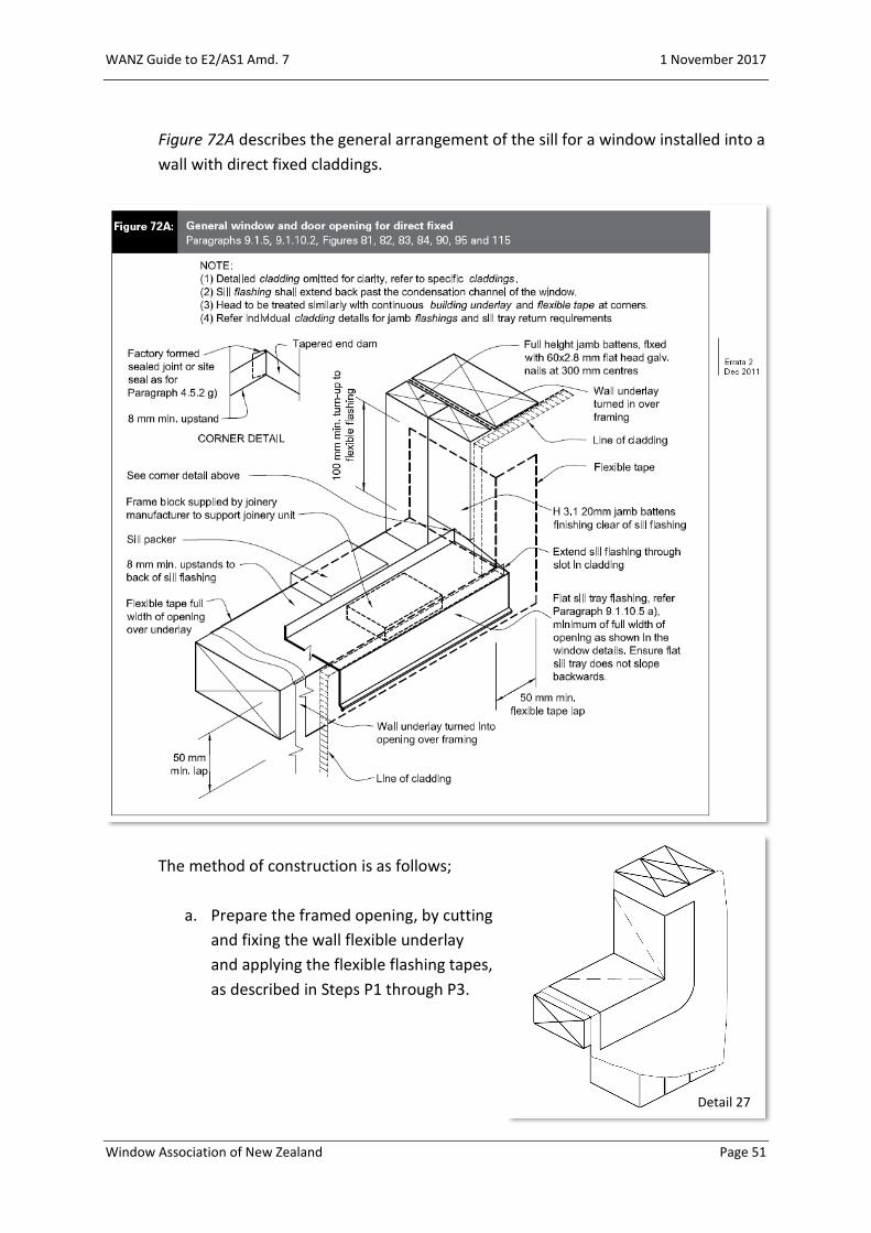
Figure 72A describes the general arrangement of the sill for a window installed into a
wall with direct fixed claddings.
The method of construction is as follows;
a. Prepare the framed opening, by cutting
and fixing the wall flexible underlay
and applying the flexible flashing tapes,
as described in Steps P1 through P3.
Detail 27
WANZ Guide to E2/AS1 Amd. 7 1 November 2017
Window Association of New Zealand Page 52
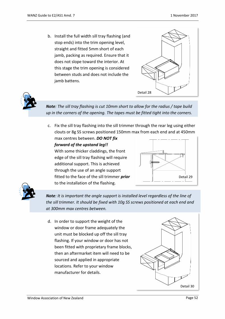
b. Install the full width sill tray flashing (and
stop ends) into the trim opening level,
straight and fitted 5mm short of each
jamb, packing as required. Ensure that it
does not slope toward the interior. At
this stage the trim opening is considered
between studs and does not include the
jamb battens.
Note: The sill tray flashing is cut 10mm short to allow for the radius / tape build
up in the corners of the opening. The tapes must be fitted tight into the corners.
c. Fix the sill tray flashing into the sill trimmer through the rear leg using either
clouts or 8g SS screws positioned 150mm max from each end and at 450mm
max centres between. DO NOT fix
forward of the upstand leg!!
With some thicker claddings, the front
edge of the sill tray flashing will require
additional support. This is achieved
through the use of an angle support
fitted to the face of the sill trimmer prior
to the installation of the flashing.
Note: It is important the angle support is installed level regardless of the line of
the sill trimmer. It should be fixed with 10g SS screws positioned at each end and
at 300mm max centres between.
d. In order to support the weight of the
window or door frame adequately the
unit must be blocked up off the sill tray
flashing. If your window or door has not
been fitted with proprietary frame blocks,
then an aftermarket item will need to be
sourced and applied in appropriate
locations. Refer to your window
manufacturer for details.
Detail 29
Detail 30
Detail 28

WANZ Guide to E2/AS1 Amd. 7 1 November 2017
Window Association of New Zealand Page 53
e. Figure 72A (shown on Page 51) describes the addition of full height battens
to each jamb of the trim opening. These
battens are fitted after all of the trim
opening preparation has been
completed, including flashing tape, sill
tray flashings and end stops.
The battens are used as described in
Clause 9.1.8.4 f).
Comment: It would be good practice to bed the inner
batten on sealant to help prevent / reduce air
leakage around the primary air seal.
f. The cladding is now installed and must
be notched around the sill tray flashing,
and support angle where it is used.
Note: It is important to discuss the building details, including the batten size, with
your window manufacturer to ensure the window sizes are calculated correctly.
- Sealant
Detail 31
Detail 32

WANZ Guide to E2/AS1 Amd. 7 1 November 2017
Window Association of New Zealand Page 54
Step D2 – Position the Unit
a. Before positioning the window or door unit into the opening ensure, where
applicable, that the sill corners
have been fitted with corner
soaker as described in Clause
9.1.10.5 c).
Check with your window
manufacturer regarding the
types of corner soaker used
with their systems and that
they are indeed applicable.
b. Ensure the unit is positioned so that;
i) The unit is positioned 5mm
forward of the exterior cladding
line, as described in Clause
9.1.10.2 b),
ii) The interior linings will finish in the correct positions,
iii) The unit is sitting correctly on
the sill tray flashing,
iv) Once the installation has been completed, the required cover over the
exterior cladding as
described in Clause
9.1.10, has been
achieved.
Detail 33

WANZ Guide to E2/AS1 Amd. 7 1 November 2017
Window Association of New Zealand Page 55
Step D2a – Position the Unit – Full Height
Figure 17D, describes the sill details for full height window and door units. The
positioning of the unit is essentially the same as described in Step D2 above.

WANZ Guide to E2/AS1 Amd. 7 1 November 2017
Window Association of New Zealand Page 56
Note: Some find the on-floor details described in Figure 17D to be undesirable. If so
then a rebated sill detail will need to be designed for the situation. In this case the
rebate becomes the threshold level, i.e. the floor level inside of the window or door
is irrelevant to the Acceptable Solution.
Rebated Timber Floor
Rebated Concrete Floor
Detail 35
Detail 34

WANZ Guide to E2/AS1 Amd. 7 1 November 2017
Window Association of New Zealand Page 57
Step D3 – Fixing
a. Insert flat packers between the wall framing and the window or door reveals
at the head, sill and jambs at fixing points. DO NOT use wedges.
b. Fix off the unit as described in
Clause 9.1.10.8.
Note: This Clause describes the fixing method for typical windows and doors. Larger
units or those subject to higher wind loads may require additional fixing. If in doubt,
contact your window manufacturer to confirm.
c. After fixing the unit in place, remove the packers from the head of the unit to
allow any potential settlement
of the building structure.
Detail 36
Detail 37
WANZ Guide to E2/AS1 Amd. 7 1 November 2017
Window Association of New Zealand Page 58
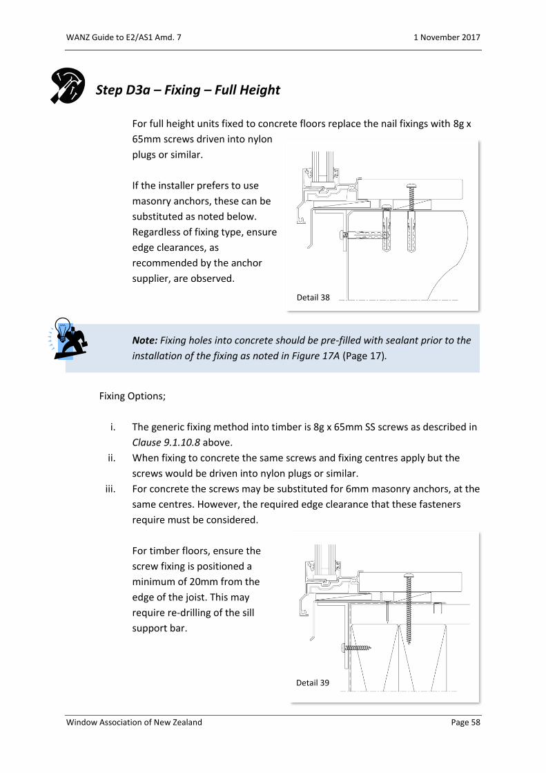
Step D3a – Fixing – Full Height
For full height units fixed to concrete floors replace the nail fixings with 8g x
65mm screws driven into nylon
plugs or similar.
If the installer prefers to use
masonry anchors, these can be
substituted as noted below.
Regardless of fixing type, ensure
edge clearances, as
recommended by the anchor
supplier, are observed.
Note: Fixing holes into concrete should be pre-filled with sealant prior to the
installation of the fixing as noted in Figure 17A (Page 17).
Fixing Options;
i. The generic fixing method into timber is 8g x 65mm SS screws as described in
Clause 9.1.10.8 above.
ii. When fixing to concrete the same screws and fixing centres apply but the
screws would be driven into nylon plugs or similar.
iii. For concrete the screws may be substituted for 6mm masonry anchors, at the
same centres. However, the required edge clearance that these fasteners
require must be considered.
For timber floors, ensure the
screw fixing is positioned a
minimum of 20mm from the
edge of the joist. This may
require re-drilling of the sill
support bar.
Detail 38
Detail 39

WANZ Guide to E2/AS1 Amd. 7 1 November 2017
Window Association of New Zealand Page 59
Step D4 – Air Seal
The Air Seal is designed to hold pressure in the trim cavity to enable pressure
equalisation to occur. Typically, the Air Seal is a low expansion polyurethane foam
installed over a PEF backing rod, as
described in Clause 9.1.6.
Note: Clause 9.1.6 makes this
comment regarding air seals.
Detail 40

WANZ Guide to E2/AS1 Amd. 7 1 November 2017
Window Association of New Zealand Page 60
Step D5 – Head Flashing
Clause 9.1.10.4 describes the basics of
head flashings.
Specifically, paragraphs c) and in some
situations e) apply to direct fix
construction.
Detail a) from Figure 81, shows the typical head flashing set out and prescribed
dimensions.
WANZ Guide to E2/AS1 Amd. 7 1 November 2017
Window Association of New Zealand Page 61
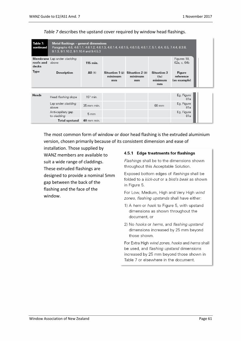
Table 7 describes the upstand cover required by window head flashings.
The most common form of window or door head flashing is the extruded aluminium
version, chosen primarily because of its consistent dimension and ease of
installation. Those supplied by
WANZ members are available to
suit a wide range of claddings.
These extruded flashings are
designed to provide a nominal 5mm
gap between the back of the
flashing and the face of the
window.
WANZ Guide to E2/AS1 Amd. 7 1 November 2017
Window Association of New Zealand Page 62
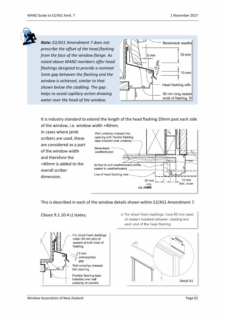
Note: E2/AS1 Amendment 7 does not
prescribe the offset of the head flashing
from the face of the window flange. As
noted above WANZ members offer head
flashings designed to provide a nominal
5mm gap between the flashing and the
window is achieved, similar to that
shown below the cladding. The gap
helps to avoid capillary action drawing
water over the head of the window.
It is industry standard to extend the length of the head flashing 20mm past each side
of the window, i.e. window width +40mm.
In cases where jamb
scribers are used, these
are considered as a part
of the window width
and therefore the
+40mm is added to the
overall scriber
dimension.
This is described in each of the window details shown within E2/AS1 Amendment 7.
Clause 9.1.10.4 c) states;
Detail 41
WANZ Guide to E2/AS1 Amd. 7 1 November 2017
Window Association of New Zealand Page 63
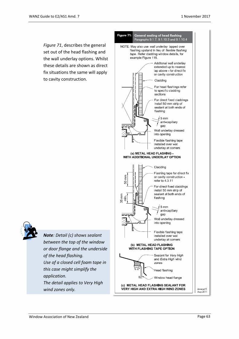
Figure 71, describes the general
set out of the head flashing and
the wall underlay options. Whilst
these details are shown as direct
fix situations the same will apply
to cavity construction.
Note: Detail (c) shows sealant
between the top of the window
or door flange and the underside
of the head flashing.
Use of a closed cell foam tape in
this case might simplify the
application.
The detail applies to Very High
wind zones only.

WANZ Guide to E2/AS1 Amd. 7 1 November 2017
Window Association of New Zealand Page 64
Note: Windows or doors that extend to the soffit do not require a head flashing but
instead will have
a trim fitted as
shown in Figure
8A f).
Refer to pages 31-36 for details relating to installation up to a soffit.
WANZ Guide to E2/AS1 Amd. 7 1 November 2017
Window Association of New Zealand Page 65
WANZ Components – Direct Fix Claddings

WANZ Guide to E2/AS1 Amd. 7 1 November 2017
Window Association of New Zealand Page 66

WANZ Guide to E2/AS1 Amd. 7 1 November 2017
Window Association of New Zealand Page 67
Direct Fix Claddings
Typical Details
WANZ Guide to E2/AS1 Amd. 7 1 November 2017
Window Association of New Zealand Page 68

WANZ Guide to E2/AS1 Amd. 7 1 November 2017
Window Association of New Zealand Page 69
WANZ Guide to E2/AS1 Amd. 7 1 November 2017
Window Association of New Zealand Page 70

WANZ Guide to E2/AS1 Amd. 7 1 November 2017
Window Association of New Zealand Page 71

WANZ Guide to E2/AS1 Amd. 7 1 November 2017
Window Association of New Zealand Page 72
WANZ Guide to E2/AS1 Amd. 7 1 November 2017
Window Association of New Zealand Page 73
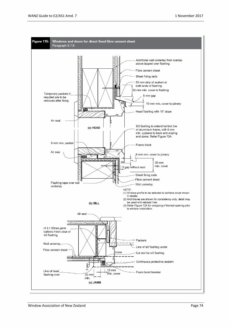
WANZ Guide to E2/AS1 Amd. 7 1 November 2017
Window Association of New Zealand Page 74

Altus NZ Ltd Specific Products - Installation Details
Altus NZ Ltd is a Window Association of New Zealand member Page 75
Altus NZ Ltd Specific ProductsInstallation details
Installation details for: The Eurostacker®, Euroslider®, Foldback® Bifold and the CodeMark certified Smartfit® Window Technology.

Altus NZ Ltd Specific Products - Euroslider® Cavity Construction Installation Details (Pacific Suite ranges)
Altus NZ Ltd is a Window Association of New Zealand member Page 76
Euroslider®EUROSLIDER® - HEAD DETAIL
EUROSLIDER® - SILL DETAIL EUROSLIDER® - REBATED SILL DETAIL
EUROSLIDER® - JAMB DETAIL
Cladding
Wanz HeadFlashing End Dam
Water resistant 'Air Seal'to perimeter of trim cavity
Do not push gib hardinto groove
No packers at head
Head flashing.Do not fit hard downonto frame
Foam tape
Nail fix bottomrolling doorhead reveals.
Bottom Rolling EuroSlider
Install bracket 78619/16 withlegs ripped to suit claddingthickness. Fix to lintel with3x min 8g wood screwsDrill channel infilland frame thentighten machinescrew into bracketSecure clip inextrusion to framewith 2x 6G screws.All framepenetrations to besealed over.
WANZ SupportBar
Flat packers tosupport unit Sill Detail
Fixings to suitsubstrate at450 ctrs
78752CornerSoaker
Bevel-backWeatherboard
Line of headflashing above
Flat packers tosupport unit
Water resistant 'AirSeal' to perimeterof trim cavity
Jamb Detail (At Sidelight)Jamb Detail (At Lock)
Cut 331271 x 250 long.1 at mid point of jamb (or near strike) and1 directly at overlight transom (if present).
Pre fix 2x 8g Csk 13 screw &washers through slot of flat.
Conceal screw through strike & selftap into flat (pilot hole). All framepenetrations to be sealed over.
Method:1) Rip legs of angle to suit cladding thickness. Screw fix to front face of lintel.2) Screw fix similar ripped angles to jamb stud work as per notes.3) Fix selected support angle and sill flashing in place. Locate appropriate packers.4) Position unit into trimmed opening and 'tack off' through liners.5) Screw fix off remainder of unit through reveals as detailed.
Note:Use angles as shown prior to the building cladding being in place.
Refer the weather tightness details on the appropriate claddings page in the WANZ Manual.
Some thinner cavity claddings may need the wall framing packed to fit the long reach of the stacker door frame into the overall wall thickness.
NOTE: Rebate Depthand Height may varyfrom what is shown
336672
336678
336607
336677
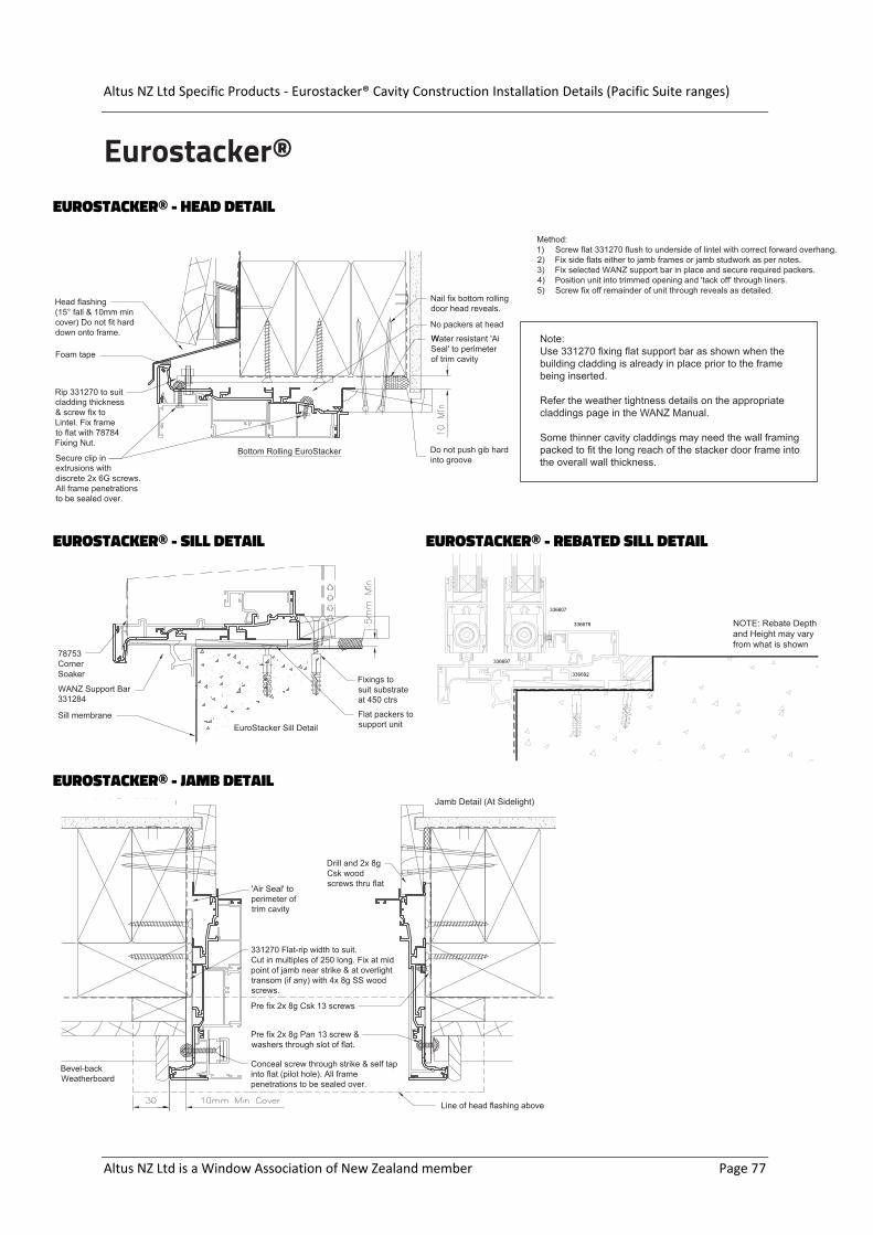
Altus NZ Ltd Specific Products - Eurostacker® Cavity Construction Installation Details (Pacific Suite ranges)
Altus NZ Ltd is a Window Association of New Zealand member Page 77
Eurostacker®
336678
336607
336692
336697
NOTE: Rebate Depthand Height may varyfrom what is shown.
EUROSTACKER® - HEAD DETAIL
EUROSTACKER® - SILL DETAIL EUROSTACKER® - REBATED SILL DETAIL
EUROSTACKER® - JAMB DETAIL
Note:Use 331270 fixing flat support bar as shown when the building cladding is already in place prior to the frame being inserted.
Refer the weather tightness details on the appropriate claddings page in the WANZ Manual.
he wall framing Some thinner cavity claddings may need tpacked to fit the long reach of the stacker door frame into the overall wall thickness.
e DepthNOTE: Rebatand Height may varyfrom what is shown
W resistant 'AiSeal'Water
to perimeterof trim cavity
Do not push gib hardinto groove
No packers at head
Head flashing(15° fall m min& 10mcover) Do not fit harddown onto frame.
Foam tape
Nail fix bottom rollingdoor head reveals.
Bottom Rolling EuroStacker
Rip 331270 to suitcladding thickness& screw fix toLintel. Fix frame
flat with 78784to Fixing Nut.
Secure clip inextrusions withdiscrete 2x 6G screws.All frame penetrationsto be sealed over.
Bevel-backWeatherboard
'Air Seal' toperimeter oftrim cavity
Jamb DetaiJamb Detail (At Lock) l (At Lock)
331270 Flat-rip width to suit.Cut in multiples of 250 long. Fix at midpoint of jamb near strike & at overlighttransom (if any) with 4x 8g SS woodscrews.
Pre fix 2x 8g Pan 13 screw &washers through slot of flat.
Pre fix 2x 8g Csk 13 screws
Drill and 2x 8gCsk woodscrews thru flat
Conceal screw through strike & self tapinto flat (pilot hole). All framepenetrations to be sealed over.
Line of head flashing above
EuroStacker Sill Detail
WANZ Support Bar331284
Flat packers tosupport unit
Sill membrane
Fixings tosuit substrateat 450 ctrs
78753erCorn
Soaker
Method:1) Screw flat 331270 flush to underside of lintel with correct forward overhang.2) Fix side flats either to jamb frames or jamb studwork as per notes.3) Fix selected WANZ support bar in place and secure required packers.4) Position unit into trimmed opening and 'tack off' through liners.5) Screw fix off remainder of unit through reveals as detailed.
) Jamb Detail (At Sidelight
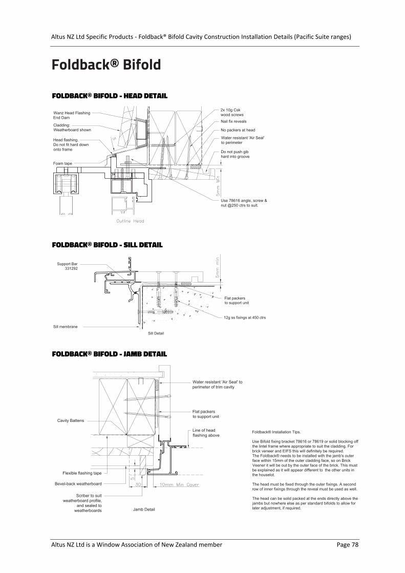
Altus NZ Ltd Specific Products - Foldback® Bifold Cavity Construction Installation Details (Pacific Suite ranges)
Altus NZ Ltd is a Window Association of New Zealand member Page 78
Foldback® Bifold
FOLDBACK® BIFOLD - HEAD DETAIL
FOLDBACK® BIFOLD - SILL DETAIL
FOLDBACK® BIFOLD - JAMB DETAIL
Cladding:Weatherboard shown
Wanz Head FlashingEnd Dam
Water resistant 'Air Seal'to perimeter
Do not push gibhard into groove
No packers at head
Head flashing. downDo not fit hard
onto frame
Foam tape
Nail fix reveals
Use 78616 angle, screw &nut @250 ctrs to suit.
2x 10g Cskwood screws
Foldback® Installation Tips.
Use Bifold fixing bracket 78616 or 78619 or solid blocking offthe lintel frame where appropriate to suit the cladding. Forbrick veneer and EIFS this will definitely be required.The ack® needs to be installed with the jamb's outerface wi
Foldbthin 15mm of the outer cladding face, so on Brick
Veener it will be out by the outer face of the brick. This mustbe explained as it will appear different to the other units inthe houselot.
The head must be fixed through the outer fixings. A secondrow of inner fixings through the reveal must be used as well.
The head can be solid packed at the ends directly above thejambs but nowhere else as per standard bifolds to allow forlater adjustment, if required.
Sill membrane
Support Bar331292
12g ss fixings at 450 ctrs
Sill Detail
Flat packersto support unit
Jamb Detail
Flexible flashing tape
Cavity Battens
Water resistant 'Air Seal' toperimeter of trim cavity
Flat packersto support unit
Line of headflashing above
Bevel-back weatherboard
Scriber to suitweatherboard profile,
and sealed toweatherboards

Altus NZ Ltd Specific Products - Top Hung Bifold Cavity Construction Installation Details (Pacific Suite ranges)
Altus NZ Ltd is a Window Association of New Zealand member Page 79
Top Hung BifoldTOP HUNG BIFOLD - HEAD DETAIL
TOP HUNG BIFOLD - SILL DETAIL
TOP HUNG BIFOLD - JAMB DETAIL
Sill membrane
Support Bar331292
12g ss fixings at 450 ctrs
Sill Detail
Flat packersto support unit
Jamb Detail
Flexible flashing tape
Cavity Battens
Water resistant 'Air Seal' toperimeter of trim cavity
Flat packersto support unit
Line of headflashing above
Bevel-back weatherboard
Scriber to suitweatherboard profile,
and sealed toweatherboards
78616 Head bracket at 450ctr
Head flashing (15° fall &10mm min cover)Don't fit
hard down onto frame
Double screw fix thru head at450mm crs with 8g screws.
This allows later adjustment forsagging lintels
73102 cavity closer
Foam tape
No packers at head
Water resistant 'Air Seal' toperimeter of trim cavity
Do not push gib hardinto groove
Bevel-back weatherboard
Approved tape &/or house wrap over cavity closer
Cavity Battens
Cladding seal
Altus NZ Ltd Specific Products - Smartfit® Window Technology
Altus NZ Ltd is a Window Association of New Zealand member Page 80
Smartfit®
Smartfit® Window Technology
Note: The following Smartfit® installation details are only a partial representation of the details available. For the full guide call 0800 397 263 or email [email protected] to request a copy.

Altus NZ Ltd Specific Products - Smartfit® Window Technology
Altus NZ Ltd is a Window Association of New Zealand member Page 81
Smartfit®
1.2 Check trim opening for level, plumb,twist and squareness. Check outerwindow mounting surface is free from anyprotrusions and misaligned timber.
1.3 The trimmer must be fixed as such toresist torsional loads placed upon it fromthe weight of the installed and glazedwindow
1.4 Check concrete slab edge issmooth and even, devoid of spilland boxing ridges. Any substantialedge breakouts that could affectsill sealing must be reinstated
STEP 1 - Preliminary check of trim opening
1.1 IMPORTANT NOTE;The wall framing must at leastbe flush or protrude out overthe floor edge. 5mm nominal isideal.
5mm
Altus NZ Ltd Specific Products - Smartfit® Window Technology
Altus NZ Ltd is a Window Association of New Zealand member Page 82
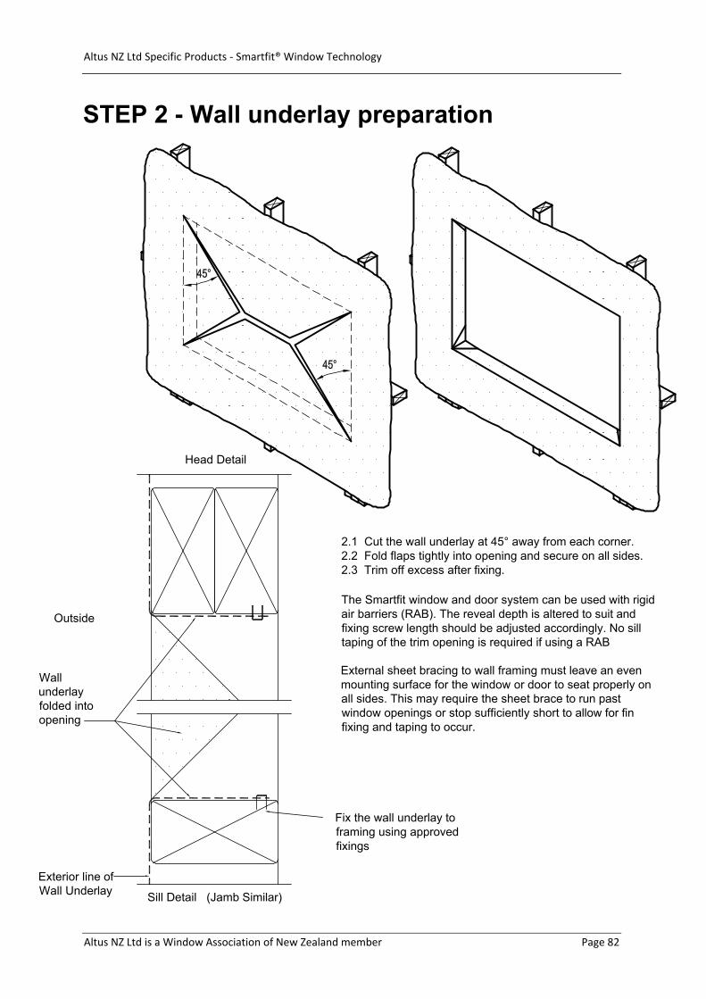
Outside
Exterior line ofWall Underlay
Fix the wall underlay toframing using approvedfixings
Sill Detail (Jamb Similar)
Head Detail
STEP 2 - Wall underlay preparation
2s.
.1 Cut the wall underlay at 45° away from each corner.2.2 Fold flaps tightly into opening and secure on all side2.3 Trim off excess after fixing.
The Smartfit window and door system can be used with rigidair barriers (RAB). The reveal depth is altered to suit andfixing screw length should be adjusted accordingly. No silltaping of the trim opening is required if using a RAB
External sheet bracing to wall framing must leave an evenmounting surface for the window or door to seat properly onall sides. This may require the sheet brace to run pastwindow openings or stop sufficiently short to allow for finfixing and taping to occur.
Wallunderlayfolded intoopening

Altus NZ Ltd Specific Products - Smartfit® Window Technology
Altus NZ Ltd is a Window Association of New Zealand member Page 83
STEP 3 - Position unit in opening
3.1 Position unit into opening.
s3.2 Push outer fixing flange hard against the framing ensuring it ievenly seated and devoid of twist. Minor shimming under outer fixingfin is permissible to eliminate twist or to position window accurately tothe reveal wall board groove or architrave.
,3.4 Use full depth rectangular packers between framing and revealto level the unit if required. If the floor or trimmer is straight and levelthe window or door may sit hard down.
3.5 Diagonally measure to check for square and pack reveals ifrequired.
3.6 Fix off unit as described in Step 4
3.7 Remove any packers from head reveal area
3.8 Cladding fixing s tst
tr
a
i
r
m
after window install.
gap dimension between reveal and framingisNote; The remaining
not important.

Altus NZ Ltd Specific Products - Smartfit® Window Technology
Altus NZ Ltd is a Window Association of New Zealand member Page 84
STEP 4 - Fix off unit
4.2 Fixing requirements @Head & Jambs through outer fin;
10g x 32 SS screws @ 300 ctrs andnot more than 150mm fromcorners
Holes are pre machined in headand jambs for screw fixings.
4.3 Fixing requirements @ Sill.10g x 32 SS screws @ 300 ctrs notmore than 150mm from Corners.Holes are pre machined in sill forfixings. Refer to subsequent detailsfor timber or concrete sill fixing.
4.4 Reveal Fixing:The reveal is not the primary means for attaching thewindow to the building. The frequency of reveal fixingsand packers should follow good carpentry practice toprevent the reveal from being unduly flexible in service.Remove any head packers after fixing reveals.If no head flashing is present, reveal fixings at the headare required in accordance with 4.5.Sliding and hinged door jambs at lock points will requirea positive reveal fixing. Pack between reveal and houseframing and nail fix reveal to a suitable standard toresist jamb movement from potential lock loads.
4.5 Windows with head hard to soffit and no head flashingrequired (not shown);Fixings: 2 off 75mm Jolt Head Nails@ 450ctrs and not more than 150mm from each end throughreveal at head only. See IN-43 for example.
4.1 Do not fix through any plasticparts.
Note;Before attempting to install a Smartfit window unit,installers are advised to familiarise themselveswith the Smartfit window system componentsshown on Dwg. No's IN-04 and IN-05.
Altus NZ Ltd Specific Products - Smartfit® Window Technology
Altus NZ Ltd is a Window Association of New Zealand member Page 85
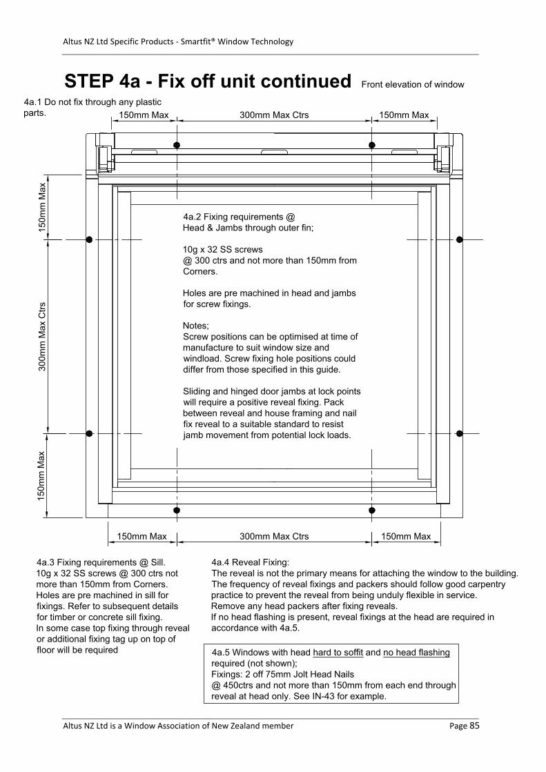
STEP 4a - Fix off unit continued
4a.2 Fixing requirements @Head & Jambs through outer fin;
10g x 32 SS screws@ 300 ctrs and not more than 150mm fromCorners.
Holes are pre machined in head and jambsfor screw fixings.
Notes;Screw positions can be optimised at time ofmanufacture to suit window size andwindload. Screw fixing hole positions coulddiffer from those specified in this guide.
Sliding and hinged door jambs at lock pointswill require a positive reveal fixing. Packbetween reveal and house framing and nailfix reveal to a suitable standard to resistjamb movement from potential lock loads.
4a.3 Fixing requirements @ Sill.10g x 32 SS screws @ 300 ctrs notmore than 150mm from Corners.Holes are pre machined in sill forfixings. Refer to subsequent detailsfor timber or concrete sill fixing.In some case top fixing through revealor additional fixing tag up on top offloor will be required
4a.4 Reveal Fixing:The reveal is not the primary means for attaching the window to the building.The frequency of reveal fixings and packers should follow good carpentrypractice to prevent the reveal from being unduly flexible in service.Remove any head packers after fixing reveals.If no head flashing is present, reveal fixings at the head are required inaccordance with 4a.5.
4a.1 Do not fix through any plasticparts.
150mm Max 150mm Max300mm Max Ctrs
150mm Max300mm Max Ctrs150mm Max
150m
m M
ax15
0mm
Max
300m
m M
ax C
trs
Front elevation of window
4a.5 Windows with head hard to soffit and no head flashingrequired (not shown);Fixings: 2 off 75mm Jolt Head Nails@ 450ctrs and not more than 150mm from each end throughreveal at head only. See IN-43 for example.

Altus NZ Ltd Specific Products - Smartfit® Window Technology
Altus NZ Ltd is a Window Association of New Zealand member Page 86
STEP 4b - Fix off unit continued
4b.4 FIXING REQUIREMENTS @Sill.10g x 32 SS screws @ 300 ctrs notmore than 150mm from Corners.
4b.2 Fixing requirements @Head &Jambs;10g x 32 SS screws @ 300 ctrs and notmore than 150mm from Corners.
4b.5 Reveal fixing:*See note 4.4 on sheet IN-09
4b.6 Fixing requirements @head & jambs.10g x 32 SS screws @ 300 ctrsnot more than 150mm from corners.
HEAD
SILL
JAMB
Note: Use top row of holesfor fixing into timber, Usebottom row for fixing intoConcrete.
Packer
4b.3 Note: Window reveal to buildingframing trim clearances are notimportant. 5mm nominal shown allround to allow for squaring unit.
4b.1 For windows with head hard to soffitand no head flashing present (not shown);See specific detail on Dwg. No. IN-43.
NOTE: Heavy duty head flashing (shownN.T.S) is required for Bi-fold door units.See specific detail on Dwg. no. IN-53.
Minor shimming under outer is permissible tofixing
eliminate twist or to positionwindow accurately to thereveal wall board groove orarchitrave
fin
.
Vertical and Horizontal cross section of unit
Altus NZ Ltd Specific Products - Smartfit® Window Technology
Altus NZ Ltd is a Window Association of New Zealand member Page 87
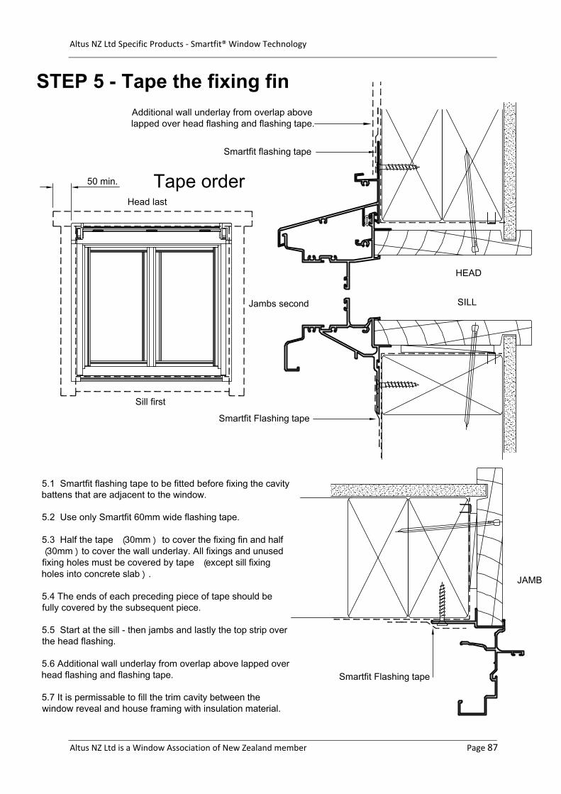
STEP 5 - Tape the fixing fin
5.1 Smartfit flashing tape to be fitted before fixing the cavitybattens that are adjacent to the window.
5.2 Use only Smartfit 60mm wide flashing tape.
5.3 Half the tape (30mm ) to cover the fixing fin and half30mm )to cover the wall underlay. All fixings and unusedi
(
nfix g holes must be covered by tape (except sill fixingholes into concrete slab ).
of tape should be5.4 The ends of each preceding pifully covered by the subsequent piece
ece.
5.5 Start at the sill - then jambs and lastly the top strip overthe head flashing.
5.6 Additional wall underlay from overlap above lapped overhead flashing and flashing tape.
5.7 It is permissable to fill the trim cavity between thewindow reveal and house framing with insulation material.
Sill first
Jambs second
Head last
Tape order
Smartfit flashing tape
Smartfit Flashing tape
Smartfit Flashing tape
HEAD
SILL
JAMB
50 min.
Additional wall underlay from overlap abovelapped over head flashing and flashing tape.
Altus NZ Ltd Specific Products - Smartfit® Window Technology
Altus NZ Ltd is a Window Association of New Zealand member Page 88
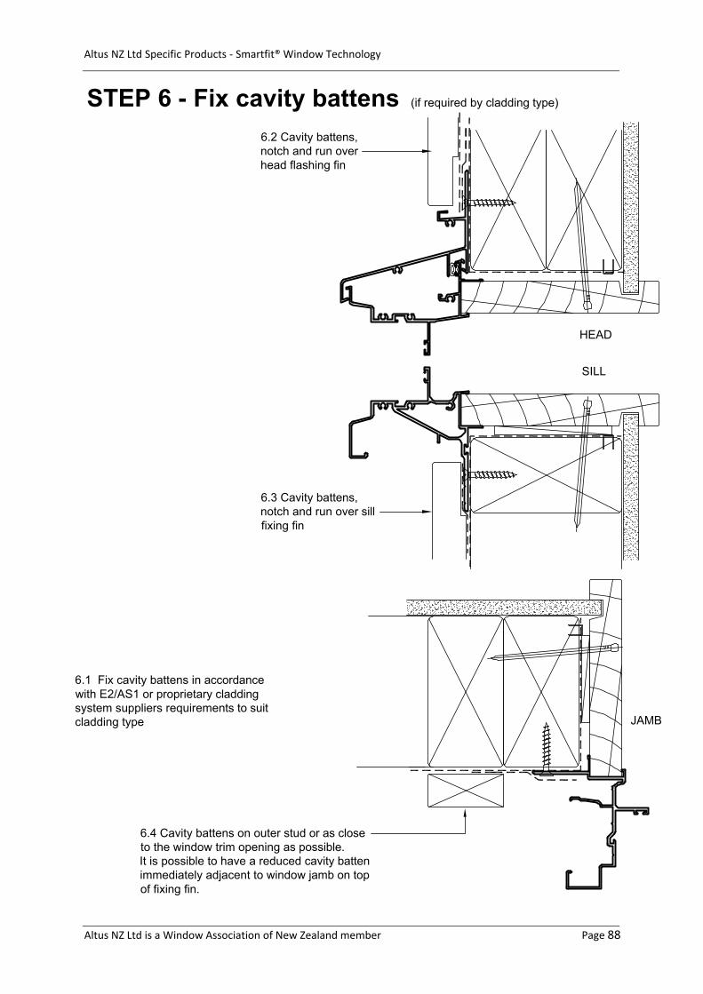
STEP 6 - Fix cavity battens
6.2 Cavity battens,notch and run overhead flashing fin
6.1 cladding
Fix cavity battens in accordancewith E2/AS1 or proprietarysystem suppliers requirements to suitcladding type
HEAD
SILL
JAMB
6.3 Cavity battens,notch and run over sillfixing fin
6.4 Cavity battens on outer stud or as closeto the window trim opening as possible.It is possible to have a reduced cavity battenimmediately adjacent to window jamb on topof fixing fin.
(if required by cladding type)

Altus NZ Ltd Specific Products - Smartfit® Window Technology
Altus NZ Ltd is a Window Association of New Zealand member Page 89
STEP 7 - Fit cladding
Bevel-back weatherboard
Bevel-backweatherboard
Cavity battens
HEAD
SILL
JAMB
Cant strip
Bevel-backweatherboard
Cavity battens
Scriber
Min 8
Weatherboard shown, example
8 m
in c
ove
rCladdingreferences top hub
Cavity battens
In all cases, cladding is fitted afterwindow installation. Sheet claddingproducts will need joins to allowcladding to be presented about awindow after the window is in position.
Altus NZ Ltd Specific Products - Smartfit® Window Technology
Altus NZ Ltd is a Window Association of New Zealand member Page 90
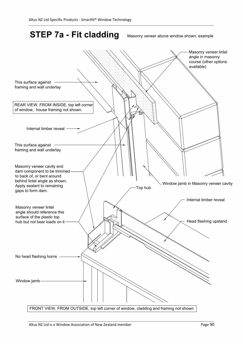
STEP 7a - Fit cladding
Masonry veneer cavity enddam component to be trimmedto back of, or bent aroundbehind lintel angle as shown.Apply sealant to remaininggaps to form dam.
Masonry veneer lintelangle should reference thissurface of the plastic tophub but not bear loads on it
FRONT VIEW, FROM OUTSIDE, top left corner of window, cladding and framing not shown
Masonry veneer above window shown, example
Masonry veneer lintelangle in masonrycourse (other optionsavailable)
Internal timber reveal
Head flashing upstand
Top hub
Window jamb
No head flashing horns
Window jamb in Masonry veneer cavity
Internal timber reveal
This surface againstframing and wall underlay
This surface againstframing and wall underlay
REAR VIEW, FROM INSIDE, top left cornerof window, house framing not shown.
Altus NZ Ltd Specific Products - Smartfit® Window Technology
Altus NZ Ltd is a Window Association of New Zealand member Page 91
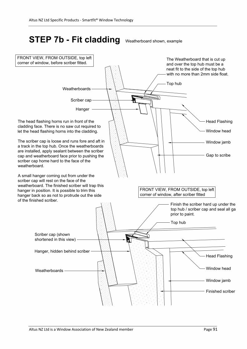
STEP 7b - Fit cladding
Head Flashing
The head flashing horns run in front of thecladding face. There is no saw cut required tolet the head flashing horns into the cladding.
The scriber cap is loose and runs fore and aft ina track in the top hub. Once the weatherboardsare installed, apply sealant between the scribercap and weatherboard face prior to pushing thescriber cap home hard to the face of theweatherboard.
A small hanger coming out from under thescriber cap will rest on the face of theweatherboard. The finished scriber will trap thishanger in position. It is possible to trim thishanger back so as not to protrude out the sideof the finished scriber.
Scriber cap
Hanger
Weatherboards
The Weatherboard that is cut upand over the top hub must be aneat fit to the side of the top hubwith no more than 2mm side float.
FRONT VIEW, FROM OUTSIDE, top leftcorner of window, before scriber fitted.
FRONT VIEW, FROM OUTSIDE, top leftcorner of window, after scriber fitted
Scriber cap (shownshortened in this view)
Window jamb
Finished scriber
Top hub
Head Flashing
Window head
Window jamb
Gap to scribe
Weatherboards Window head
Top hub
Finish the scriber hard up under thetop hub / scriber cap and seal all gaprior to paint.
Weatherboard shown, example
Hanger, hidden behind scriber
Altus NZ Ltd Specific Products - Smartfit® Window Technology
Altus NZ Ltd is a Window Association of New Zealand member Page 92
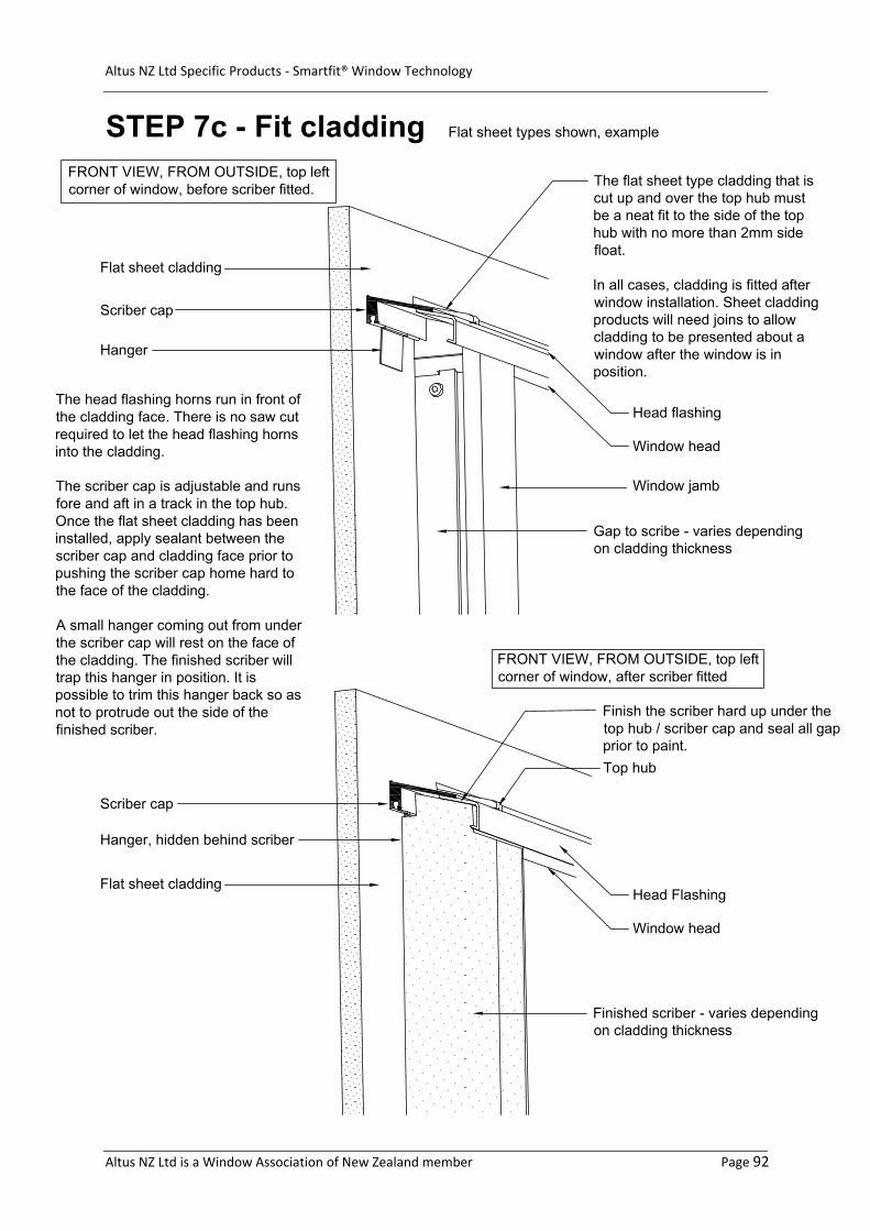
STEP 7c - Fit cladding
Scriber cap
Hanger
The head flashing horns run in front ofthe cladding face. There is no saw cutrequired to let the head flashing hornsinto the cladding.
The scriber cap is adjustable and runsfore and aft in a track in the top hub.Once the flat sheet cladding has beeninstalled, apply sealant between thescriber cap and cladding face prior topushing the scriber cap home hard tothe face of the cladding.
A small hanger coming out from underthe scriber cap will rest on the face ofthe cladding. The finished scriber willtrap this hanger in position. It ispossible to trim this hanger back so asnot to protrude out the side of thefinished scriber.
Flat sheet cladding
The flat sheet type cladding that iscut up and over the top hub mustbe a neat fit to the side of the tophub with no more than 2mm sidefloat.
In all cases, cladding is fitted afterwindow installation. Sheet claddingproducts will need joins to allowcladding to be presented about awindow after the window is inposition.
Window jamb
Head flashing
Window head
Gap to scribe - varies dependingon cladding thickness
Head Flashing
Window head
Finished scriber - varies dependingon cladding thickness
Top hub
Finish the scriber hard up under thetop hub / scriber cap and seal all gapprior to paint.
Flat sheet types shown, example
Flat sheet cladding
Scriber cap
Hanger, hidden behind scriber
FRONT VIEW, FROM OUTSIDE, top leftcorner of window, after scriber fitted
FRONT VIEW, FROM OUTSIDE, top leftcorner of window, before scriber fitted.

0800 397 263 [email protected]
The WANZ Guide to Window Installation | 1 November 2017 | Version 1.4