installation instructions winch bumper - · pdf fileinstallation instructions. winch bumper....
TRANSCRIPT

WARN INDUSTRIES PAGE 1 85632A0©2007 Warn Industries, Inc.WARN® and the WARN logo are trademarks of Warn Industries Inc.
INSTALLATION INSTRUCTIONSWINCH BUMPER
Part Number: 85623Applications: 2011+ BRP COMMANDER
Your safety, and the safety of others, is very important. To help you make informed decisions about safety, we have provided installation and operating instructions and other information on labels and in this guide. This information alerts you to potential hazards that could hurt you or others. It is not possible to warn you about all potential hazards associated with this product, you must use your own good judgment. CARELESS INSTALLATION AND OPERATION CAN RESULT IN SERIOUS INJURY OR EQUIPMENT DAMAGE. READ AND UNDERSTAND ALL SAFETY PRECAUTIONS AND OPERATING INSTRUC-TIONS BEFORE INSTALLING AND OPERATING THIS PRODUCT.This guide identifies potential hazards and has important safety messages that help you and others avoid personal injury or death. WARNING and CAUTION are signal words that identify the level of hazard. These signal words mean: WARNING signals a hazard that could cause serious injury or death, if you do not follow recommendations. CAUTION signals a hazard that may cause minor to moderate injury, if you do not follow recommendations.This guide uses NOTICE to call attention to important mechanical information, and Note: to emphasize general information worthy of special attention.
INJURY HAZARD Failure to observe these instructions could lead to severe injury or death.
Always use extreme caution when cutting and trimming during fitting. Always remove jewelry and wear eye protection. Always use appropriate and adequate care in lifting components into place. Always insure components will remain secure during installation and operation. Always tighten all nuts and bolts securely, per the installation and operation. Always perform regular inspections and maintenance on the bumper and related hardware. Never operate this WARN product with damaged or missing parts.
WARNING

WARN INDUSTRIES PAGE 2 85632A0©2007 Warn Industries, Inc.WARN® and the WARN logo are trademarks of Warn Industries Inc.
NoticeEquipment Damage
Always refer to the Installation and Specification Guide, supplied in the winch kit, for all wiring schematics and specific details on how to wire this WARN product to your vehicle.
Read installation and operating instructions thoroughly.
I. TABLE OF CONTENTS
Tools Required page 2Fastener Torque Specifications page 2Parts List page 3Installation page 4-10Maintenance/Care page 11
CautionMoving Parts Entanglement Hazard
Failure to observe these instructions could lead to minor or moderate injury. Always take time to fully read and understand the installation and Operations Guide included with this product.Never operate this product if you are under 16 years of age.Never operate this product when under the influence of drugs, alcohol or medications.
Read installation and operating instructions thoroughly.
II. TOOLS REQUIRED
- 3/8” drive ratchet - 3/8” drive 3 in. extension - 3/8” drive 6 in. extension - 13mm, 14mm socket - 14m, 9/16 end wrench - 5mm allen wrench or socket driver
III. FASTENER TORQUE SPECIFICATIONS
1/4 & M6 8 lb. ft. (10.8 N-m)5/16 & M8 17 lb. ft. (12.5 N-m)3/8 & M10 30 lb. ft. (40.7 N-m)7/16 50 lb. ft. (67.8 N-m)1/2 75 lb. ft. (101.7 N-m)
NOTE: This bumper includes mounting holes for WARN winch and trail lights, which are sold separately.
NOTE: If vehicle is equipped with winch from the factory, you will need to order PN79618 kit. This will supply you with longer cables from the contactor to the winch.

WARN INDUSTRIES PAGE 3 85632A0©2007 Warn Industries, Inc.WARN® and the WARN logo are trademarks of Warn Industries Inc.
IV. PARTS LIST Ref Qty Description A1 1 BRACKET SUPPORT BUMPER A2 1 BRACKET FRAME LH BUMPER A3 1 BRACKET FRAME RH BUMPER A4 1 WELDMENT BRP COMMANDER BUMPER A5 1 BRACKET SUPPORT BUMPER A6 2 PLATE STRAP A7 2 BRACKET FRAME SUPPORT A8 1 BRACKET GRILL A9 1 PLATE GRILL BUMPER A10 1 WELDMENT BRUSH TUBE BRP COMMANDER B1 20 M8 1.25 X 25-HEXHEAD CAPSCREW B2 48 5/16 FLAT WASHER B3 20 M8 X 1.25 – LOCKING HEX NUT B4 4 U-BOLT – 5/16 – 18 X 1 ½ X 2 B5 12 5/16 – 18 – LOCKING HEX NUT B6 6 5/16 – LOCK WASHER B7 4 5/16 – 18 X 1 - ¼ HEX SCKT BTN HD BLK B8 4 BOLT – 3/8 – 16 X 1.0 CARRIAGE HEAD BOLT B9 4 3/8 -16 – LOCKING HEX INSERT NUT B10 4 3/8 FLAT WASHER B11 2 M8 – 1.25 X 60MM HEX HEAD CAP SCREW B12 1 M8 – 1.25 X 30 – HEX HEAD CAPSCREW

WARN INDUSTRIES PAGE 4 85632A0©2007 Warn Industries, Inc.WARN® and the WARN logo are trademarks of Warn Industries Inc.
Figure 1
Figure 2
Figure 3
V. INSTALLATION
1. Remove the factory front bumper by removing the four fasteners using a torques head driver shown in figure 1.
2. Remove the two torque head screws that hold the front fascia plastic. See figure 2.
3. Remove the hood on front of vehicle, exposing the air box. Shown in figure 3.

WARN INDUSTRIES PAGE 5 85632A0©2007 Warn Industries, Inc.WARN® and the WARN logo are trademarks of Warn Industries Inc.
Figure 4
Figure 5
4. Remove the two front air box bolts using a 10mm socket shown in figure 4.
5. Attach bracket A1 underneath the front of vehicle,
align the four holes at the top to the cross brace just under the front of the air box. Take two of the u-bolts supplied and attach the plate to the tubes as shown in figure 5. Do not tighten.
6. With the u-bolts holding the plate in place, insert the M8 bolts 25mm long through the four holes just under the tabs of the air box. Thus connecting the plate to the cross brace. You may have to lift up on air box to obtain clearance to access holes. See figure 6.
Figure 6

WARN INDUSTRIES PAGE 6 85632A0©2007 Warn Industries, Inc.WARN® and the WARN logo are trademarks of Warn Industries Inc.
7. Using the supplied washers and lock nuts tighten all fasteners at this time. It may be easier to tighten the top nuts using a long extension while using an open end wrench from the top. See Figure 7.
8. Attach brackets A2 and A3 to the front of the frame using the supplied M8 x 25mm long bolts and lock washers. Attach where the factory bumper was previously attached. The brackets are slotted for any necessary adjustment required. See Figure 8.
9. Use a flat bar or scale to level brackets before You tighten all the way. Do not tighten.
10. Slide the bumper over the brackets to ensure
correct alignment of the holes. Remove bumper once you have the brackets adjusted properly you may tighten the brackets at this time. It may take the installation of an additional bracket in one of the upcoming steps before true alignment is reached.
Figure 7
Figure 8
Figure 9

WARN INDUSTRIES PAGE 7 85632A0©2007 Warn Industries, Inc.WARN® and the WARN logo are trademarks of Warn Industries Inc.
Figure 10
Bumper to be used with 2500 and 3000 lb. winches only. Do not attempt to mount 4000 lb. winch on this application, vehicle damage and operator injury or death may result.
WARNING
11. Insert the black button head bolts in the outward four corners down through the previously installed brackets. Shown in Figure 11.
12. If needed insert a punch in both the rear holes of the Bumper rear winch mounting holes and through the Frame bracket before you tighten the button head bolts. You may do one side at a time. This will aid in the installation of the winch bolts. There are access holes in the bottom of the bumper washers and lock nuts. See Figure 12 & 13.
Figure 11
Figure 12
Read the vehicle’s operator manual, winch operator manual and all warning labels prior to operation of UTV.
WARNING

WARN INDUSTRIES PAGE 8 85632A0©2007 Warn Industries, Inc.WARN® and the WARN logo are trademarks of Warn Industries Inc.
13. See previous step.
14. Install fairlead plate and winch to the top of your bumper at this time using the winch hard ware supplied with the winch. There will be one rear winch bolt that will be to short. Supplied in your hardware kit for the bumper is a M8 x 30mm long bolt, use this bolt to correct thread engagement. There are access holes in the bottom of bumper to aid in installation. See figure 14.
15. Install bracket A5 from the rear of the bumper at this time using the M8 x 25mm long bolts, flat washers, and lock nuts supplied in the bumper hardware kit. See figure 15.
Figure 13
Figure 14
Figure 15

WARN INDUSTRIES PAGE 9 85632A0©2007 Warn Industries, Inc.WARN® and the WARN logo are trademarks of Warn Industries Inc.
Figure 16
Figure 17
Figure 18
16. See figure 16.
17. It will be necessary to use a socket and extension to go through the front of the bumper to tighten the bolts on the previously installed bracket. Install the other two M8 x 25mm bolts at this time on lower ends of bumper. Tighten at this time. See figure 17.
18. Install the U-bolts to the rear of the bumper where the bumper comes in contact with the Tube shown in figure 18. See figure 18.

WARN INDUSTRIES PAGE 10 85632A0©2007 Warn Industries, Inc.WARN® and the WARN logo are trademarks of Warn Industries Inc.
19. In order to attach the lower end of the straps to the two vertical frame members you have to insert brackets A7 into the frame. Use the M8 x 60mm long bolts, flat washers, and lock nuts to secure straps. See figure 19.
20. The straps A6 are attached to the inside of the frame to the inside of the bracket shown in figure 18. Use the M8 x 25mm long bolts, flat washers, and 3/8 lock nuts to attach the straps to the top bracket. Figure 20 shows the lower end of the strap. See figure 20.
21. You are now ready to install the light bar. Use the 3/8 carriage bolts, 3/8 flat washers, and the 3/8 lock nuts to attach through the wings of bumper. You are now ready to move to the winch wiring installation portion of the winch installation book. See figure 21.
PROCEED TO SECTION TITLED “MAINTENANCE/CARE”.
Figure 19
Figure 20
Figure 21

WARN INDUSTRIES PAGE 11 85632A0©2007 Warn Industries, Inc.WARN® and the WARN logo are trademarks of Warn Industries Inc.
VI. MAINTENANCE/CARE
1. Inspect all parts on the bumper and related hardware prior to each use. Replace all hardware that appears rusted or deformed.
2. Inspect all nuts and bolts on the bumper, and related hardware prior to each use. Tighten all nuts that appear to be loose. Stripped, fractured, or bent bolts or nuts need to be replaced.
3. Check all moving or rotating parts. Remove debris that may inhibit the part from moving freely.
FAILURE TO SECURELY TIGHTEN ALL BOLTS ON THE BUMPER CAN RESULT IN PRODUCT FAILURE WHICH MAY RESULT IN VEHICLE DAMAGE AND OPERATOR INJURY OR DEATH. DOUBLE CHECK THAT ALL BOLTS ARE SE-CURELY TIGHTENED PRIOR TO USE.
WARNING
WARNINGPERFORM REGULAR INSPECTIONS ON THE BUMPER AND RELATED HARDWARE. FAILURE TO FOLLOW THIS WARNING MAY CAUSE VEHICLE DAMAGE AND OPERATOR INJURY OR DEATH.

WARN INDUSTRIES PAGE 12 85632A0©2007 Warn Industries, Inc.WARN® and the WARN logo are trademarks of Warn Industries Inc.
INSTRUCTIONS D’INSTALLATIONKIT DE PARE-CHOCS
Numéro de pièce : 85623Application: 2011+ BRP Commander
AVERTISSEMENTRISQUES DE BLESSURES
Le non-respect des instructions peut entraîner des blessures graves, voire mortelles.
Faites toujours très attention lorsque vous découpez ou taillez. Retirez toujours les bijoux et portez des lunettes de sécurité. Faites toujours attention lorsque vous déplacez des composants. Assurez-vous toujours que les composants sont bien fixés durant l’installation et l’utilisation. Serrez toujours bien tous les écrous et les boulons conformément aux instructions d’installation et
d’utilisation. Effectuez toujours régulièrement les inspections et l’entretien du treuil, de son kit de montage et du matériel
de montage connexe. Ne faites jamais fonctionner ce produit WARN avec des pièces endommagées ou manquantes.
Votre sécurité et celle des autres est très importante. Afin de vous permettre de prendre des décisions éclairées dans le domaine de la sécurité, nous vous avons fourni des instructions relatives à l’installation et à l’utilisation du produit ainsi que d’autres informations figurant sur des étiquettes et dans ce guide. Ces informations attirent l’attention sur les risques de danger pouvant vous affecter ainsi qu’autrui. Nous ne sommes pas en mesure de vous mettre en garde contre tous les dangers potentiels associés à ce produit. Il vous incombe par conséquent de faire preuve de jugement.TOUTE INSTALLATION OU UTILISATION IMPRUDENTE PEUT ENTRAÎNER DES BLESSURES GRAVES OU ENDOMMAGER L’ÉQUIPEMENT. PRENEZ SOIN DE LIRE ET DE BIEN ASSIMILER LES CONSIGNES DE SÉCURITÉ ET D’UTILISATION DU PRODUIT AVANT DE L’INSTALLER ET DE L’UTILISER.Ce guide identifie les dangers potentiels et comporte des consignes de sécurité importantes qui permettent à vous et à autrui d’éviter les risques de blessures graves ou de mort. Les termes AVERTISSEMENT et MISE EN GARDE sont des indicateurs du niveau de danger. Signification des indicateurs :Le terme AVERTISSEMENT souligne un danger potentiel qui peut entraîner des blessures graves ou la mort si vous ne suivez pas les consignes.Le terme MISE EN GARDE souligne un danger potentiel susceptible d’entraîner des blessures mineures ou modérées si vous ne suivez pas les consignes.Ce guide utilise le terme AVIS pour attirer votre attention sur des informations mécaniques importantes, et le terme Remarque : pour souligner des informations générales qui méritent une attention particulière.

WARN INDUSTRIES PAGE 13 85632A0©2007 Warn Industries, Inc.WARN® and the WARN logo are trademarks of Warn Industries Inc.
III. COUPLES DE SERRAGE DES FIXATIONS
1/4, M8 10,8 N-m (8 pi-lb)5/16 & M8 12,5 N-m (17 pi-lb)3/8 , M10 40,7 N-m (30 pi-lb)7/16 67,8 N-m (50 pi-lb)1/2 101,7 N-m (75 pi-lb)
REMARQUE : ce pare-chocs comprend des trous de montage pour le treuil et les phares longue portée WARN, vendus séparément.
REMARQUE : si le véhicule est équipé d’un treuil d’origine, vous devrez commander le kit PN79618. Il contient des câbles plus longs pour relier le contacteur au treuil.
I. TABLE DES MATIÈRES
Outils requis page 2Couples de serrage des fixations page 2Liste de pièces détachées page 3Installation page 4-10Maintenance et entretien page 11
AVISÉquipement endommagé
Reportez-vous toujours au Guide d’installation et de spécification, fourni dans le kit de treuil, pour tous les schémas de câblage et des informations détaillées concernant la façon de brancher ce produit WARN sur votre véhicule.
MISE EN GARDEDanger de happement par des pièces mobiles
Le non-respect des instructions peut entraîner des blessures mineures ou modérées.Prenez toujours le temps de bien lire et comprendre le manuel d’installation et d’utilisation inclus avec ce produit.Les personnes âgées de moins de 16 ans ne doivent jamais faire fonctionner ce produit.Ne faites jamais fonctionner ce produit sous l’effet de drogues, de l’alcool ou de médicaments.
Veuillez lire attentivement les instructions concernant l’installation et l’utilisation.
Veuillez lire attentivement les instructions concernant l’installation et l’utilisation.
II. OUTILS REQUIS
- Clé à rochet 3/8 po - Rallonge de 7,6 cm (3 po) pour clé 3/8 po - Rallonge de 15 cm (6 po) pour clé 3/8 po - Douille 13 mm, 14 mm - Clé plate simple 14 mm, 9/16 po - Clé Allen ou à douille 5 mm

WARN INDUSTRIES PAGE 14 85632A0©2007 Warn Industries, Inc.WARN® and the WARN logo are trademarks of Warn Industries Inc.
IV. PARTS LIST
Ref Qty Description A1 1 SUPPORT, PARE-CHOCS A2 1 SUPPORT DE CADRE GAUCHE, PARE-CHOCS A3 1 SUPPORT DE CADRE DROIT, PARE-CHOCS A4 1 ENSEMBLE SOUDÉ, BRP COMMANDER, PARE-CHOCS A5 1 SUPPORT, PARE-CHOCS A6 2 BANDE A7 2 SUPPORT DE CADRE A8 1 SUPPORT, CALANDRE A9 1 PLAQUE DE CALANDRE, PARE-CHOCS A10 1 ENSEMBLE SOUDÉ, TUBE DE PROTECTION, BRP COMMANDER B1 20 VIS À TÊTE HEXAGONALE M8 1,25 X 25 B2 48 RONDELLE PLATE 5/16 B3 20 ÉCROU HEXAGONAL DE BLOCAGE M8 X 1,25 B4 4 BOULON EN U, 5/16 – 18 X 1 ½ X 2 B5 12 ÉCROU HEXAGONAL DE BLOCAGE 5/16 - 18 B6 6 RONDELLE DE BLOCAGE 5/16 B7 4 VIS À TÊTE CREUSE HEXAGONALE 5/16 – 18 X 1 - ¼ B8 4 BOULON DE CARROSSERIE 3/8 – 16 X 1,0 B9 4 ÉCROU HEXAGONAL DE BLOCAGE 3/8 - 16 B10 4 RONDELLE PLATE 3/8 B11 2 VIS À TÊTE HEXAGONALE M8 – 1,25 X 60 MM B12 1 VIS À TÊTE HEXAGONALE M8 – 1,25 X 30

WARN INDUSTRIES PAGE 15 85632A0©2007 Warn Industries, Inc.WARN® and the WARN logo are trademarks of Warn Industries Inc.
Figure 1
Figure 2
Figure 3
V. INSTALLATION
1. Retirez le pare-chocs avant d’origine en enlevant les quatre fixations à l’aide d’un tournevis dynamométrique tel qu’indiqué à la figure 1.
2. Retirez les deux vis étoile qui retiennent la grille de protection avant en plastique. Voir la figure 2.
3. Retirez le capot à l’avant du véhicule, en exposant la boîte à vent. Illustré à la figure 3.
WARN INDUSTRIES PAGE 16 85632A0©2007 Warn Industries, Inc.WARN® and the WARN logo are trademarks of Warn Industries Inc.
Figure 4
Figure 5
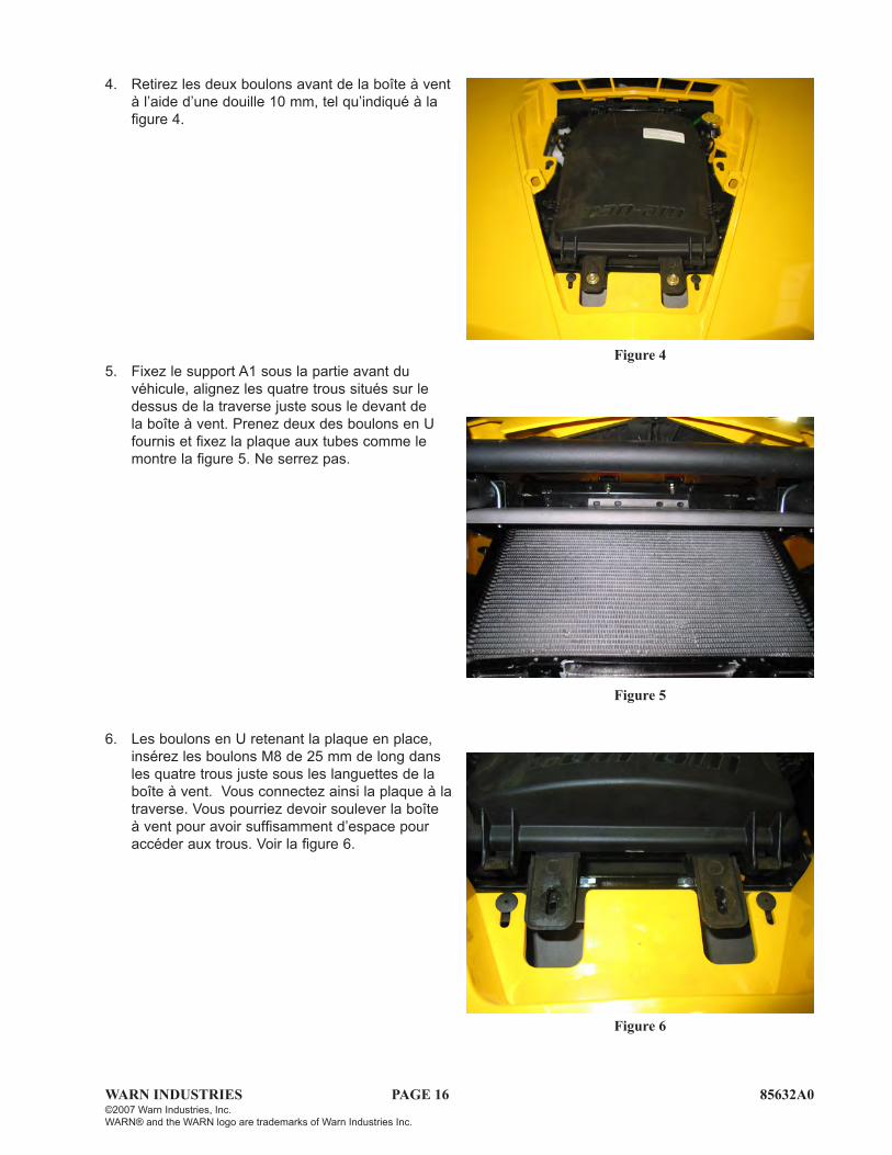
4. Retirez les deux boulons avant de la boîte à vent à l’aide d’une douille 10 mm, tel qu’indiqué à la figure 4.
5. Fixez le support A1 sous la partie avant du véhicule, alignez les quatre trous situés sur le dessus de la traverse juste sous le devant de la boîte à vent. Prenez deux des boulons en U fournis et fixez la plaque aux tubes comme le montre la figure 5. Ne serrez pas.
6. Les boulons en U retenant la plaque en place, insérez les boulons M8 de 25 mm de long dans les quatre trous juste sous les languettes de la boîte à vent. Vous connectez ainsi la plaque à la traverse. Vous pourriez devoir soulever la boîte à vent pour avoir suffisamment d’espace pour accéder aux trous. Voir la figure 6.
Figure 6

WARN INDUSTRIES PAGE 17 85632A0©2007 Warn Industries, Inc.WARN® and the WARN logo are trademarks of Warn Industries Inc.
7. À l’aide des rondelles et écrous de blocage fournis, serrez toutes les fixations à ce point. Il pourrait s’avérer plus facile de serrer les écrous du haut en utilisant une rallonge tout en utilisant une clé ouverte par le haut. Voir la figure 7.
8. Fixez les supports A2 et A3 à l’avant du cadre à l’aide des boulons M8 x 25 mm et rondelles de blocage fournis. Fixez-les à l’endroit où le pare-chocs d’origine l’était. Les supports comportent des fentes pour tout ajustement éventuel. Voir la figure 8.
9. Utilisez une barre de niveau pour mettre les supports à niveau avant de serrer à fond. Ne serrez pas.
10. Faites glisser le pare-chocs sur les supports pour assurer un alignement correct des trous. Retirer le pare-chocs une fois les supports réglés correctement; vous pouvez maintenant serrer les supports. Vous devrez peut-être installer un support supplémentaire lors de l’une des prochaines étapes avant d’obtenir un alignement parfait.
Figure 7
Figure 8
Figure 9

WARN INDUSTRIES PAGE 18 85632A0©2007 Warn Industries, Inc.WARN® and the WARN logo are trademarks of Warn Industries Inc.
Le pare-chocs est prévu pour les treuils de 1134 et 1361 kg (2500 et 3000 lb) seulement. N’essayez pas d’installer un treuil de 1814 kg (4000 lb) sur cet ensemble; cela peut endom-mager le véhicule et provoquer des blessures ou la mort de l’opérateur.
AVERTISSEMENT
Figure 10
11. Insérez les boulons à tête ronde noirs dans les quatre coins extérieurs à travers les supports déjà installés. Illustré à la figure 11.
12. En cas de besoin, introduisez un pointeau dans les trous de montage du treuil à l’arrière du pare-chocs et à travers le support du cadre avant de serrer les boulons à tête ronde. Faites-le un côté à la fois. Cela facilitera l’installation des boulons du treuil. Il y a des trous d’accès au bas du pare-chocs pour les rondelles et les écrous de blocage. Voir les figures 12 et 13.
Figure 11
Figure 12
Lisez les manuels de l’utilisateur du véhicule et du treuil ainsi que toutes les étiquettes de mise en garde avant toute utilisation du véhicule utilitaire.
AVERTISSEMENT

WARN INDUSTRIES PAGE 19 85632A0©2007 Warn Industries, Inc.WARN® and the WARN logo are trademarks of Warn Industries Inc.
13. Voir l’étape précédente.
14. Installez maintenant la plaque de guide-câble et le treuil sur le dessus du pare-chocs en utilisant le matériel fourni avec le treuil. Le kit du matériel contient un boulon de treuil arrière court. Il comprend aussi un boulon M8 x 30 mm; utilisez-le pour corriger l’engagement du filetage. Il y a des trous d’accès au bas du pare-chocs pour faciliter l’installation. Voir la figure 14.
15. Installez à présent le support A5 à l’arrière du pare-chocs en utilisant les boulons M8 x 25 mm, rondelles plates et écrous de blocage fournis dans le kit de matériel du pare-chocs. Voir la figure 15.
Figure 13
Figure 14
Figure 15
WARN INDUSTRIES PAGE 20 85632A0©2007 Warn Industries, Inc.WARN® and the WARN logo are trademarks of Warn Industries Inc.
Figure 16
Figure 17
Figure 18
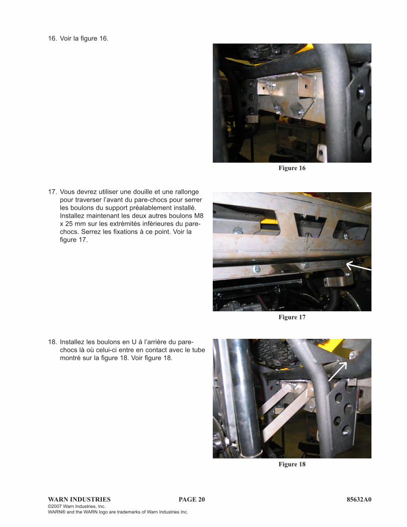
16. Voir la figure 16.
17. Vous devrez utiliser une douille et une rallonge pour traverser l’avant du pare-chocs pour serrer les boulons du support préalablement installé. Installez maintenant les deux autres boulons M8 x 25 mm sur les extrémités inférieures du pare-chocs. Serrez les fixations à ce point. Voir la figure 17.
18. Installez les boulons en U à l’arrière du pare-chocs là où celui-ci entre en contact avec le tube montré sur la figure 18. Voir figure 18.

WARN INDUSTRIES PAGE 21 85632A0©2007 Warn Industries, Inc.WARN® and the WARN logo are trademarks of Warn Industries Inc.
19. Afin de fixer l’extrémité inférieure des bandes aux deux éléments de cadre verticaux, vous devez insérer les supports A7 dans le cadre. Servez-vous des boulons M8 x 60 mm, rondelles plates et écrous de blocage pour fixer les bandes. Voir la figure 19.
20. Les bandes A6 doivent être fixées à l’intérieur du cadre à l’intérieur du support montré à la figure 18. Utilisez les boulons M8 x 25 mm, rondelles plates et écrous de blocage 3/8 pour fixer les bandes au support supérieur. La figure 20 montre l’extrémité inférieure de la bande. Voir la figure 20.
21. Vous pouvez à présent installer la barre des projecteurs. Utilisez les boulons 3/8, rondelles plates 3/8 et écrous de blocage 3/8 pour la fixer aux ailes du pare-chocs. Vous êtes maintenant prêt à passer à la section traitant de l’installation du câblage de treuil du guide d’installation du treuil. Voir la figure 21.
PASSEZ À LA SECTION INTITULÉE « MAINTENANCE/ENTRETIEN ».
Figure 19
Figure 20
Figure 21

WARN INDUSTRIES PAGE 22 85632A0©2007 Warn Industries, Inc.WARN® and the WARN logo are trademarks of Warn Industries Inc.
VI. MAINTENANCE/CARE
1. Inspectez toutes les pièces du treuil, de la plaque de montage et le matériel de montage connexe avant toute utilisation. Remplacez tout matériel qui semble rouillé ou déformé.
2. Avant toute utilisation, inspectez tous les écrous et boulons du treuil, de la plaque de montage de lame et du matériel de montage connexe. Serrez bien tous les écrous qui en ont besoin. Les écrous et boulons foirés, fracturés ou tordus doivent être remplacés.
3. Vérifiez tous les câbles avant toute utilisation. Remplacez les câbles qui semblent usés ou effilochés.
LE FAIT DE NE PAS SERRER SOLIDEMENT TOUS LES BOULONS DU TREUIL, DE LA PLAQUE DE TREUIL ET DU GUIDE-CÂBLE PEUT ENTRAÎNER UNE DÉFAILLANCE DU PRODUIT, CE QUI PEUT ENDOMMAGER LE VÉHICULE ET PROVOQUER DES BLESSURES OU LA MORT DE L’OPÉRATEUR. AVANT TOUTE UTILISATION, ASSUREZ-VOUS QUE TOUS LES BOULONS SONT BIEN SERRÉS.
AVERTISSEMENT
AVERTISSEMENTINSPECTEZ RÉGULIÈREMENT LE TREUIL, SON KIT DE MONTAGE ET LE MATÉRIEL DE MONTAGE CONNEXE. NE FAITES JAMAIS FONCTIONNER LE TREUIL AVEC DES PIÈCES ENDOMMAGÉES OU MANQUANTES. LE FAIT DE NE PAS RESPECTER CET AVERTISSEMENT PEUT FINIR PAR ENDOMMAG-ER LE VÉHICULE OU PROVOQUER DES BLESSURES GRAVES OU LA MORT DE L’OPÉRATEUR