installation instructions - electric drive systems for arm ...€¦ · installation instructions -...
TRANSCRIPT
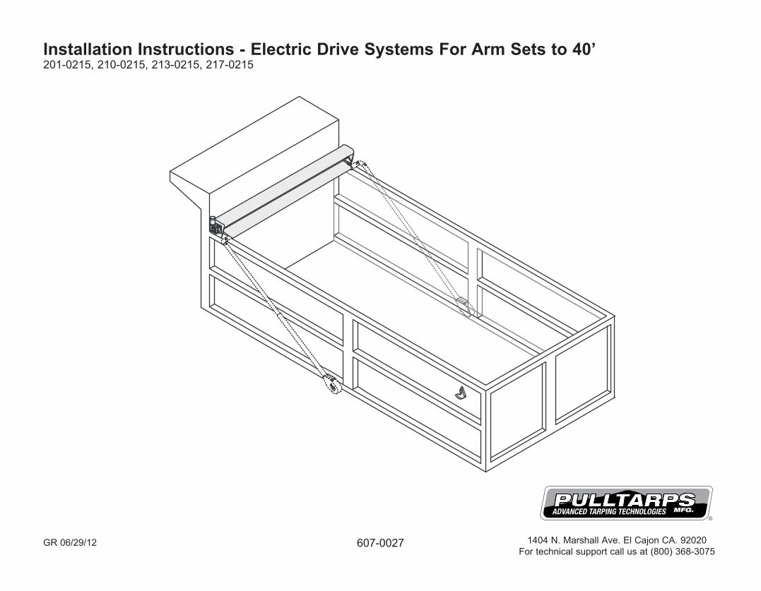
Installation Instructions - Electric Drive Systems For Arm Sets to 40’201-0215, 210-0215, 213-0215, 217-0215
607-0027 1404 N. Marshall Ave. El Cajon CA. 92020For technical support call us at (800) 368-3075
GR 06/29/12
Page 1
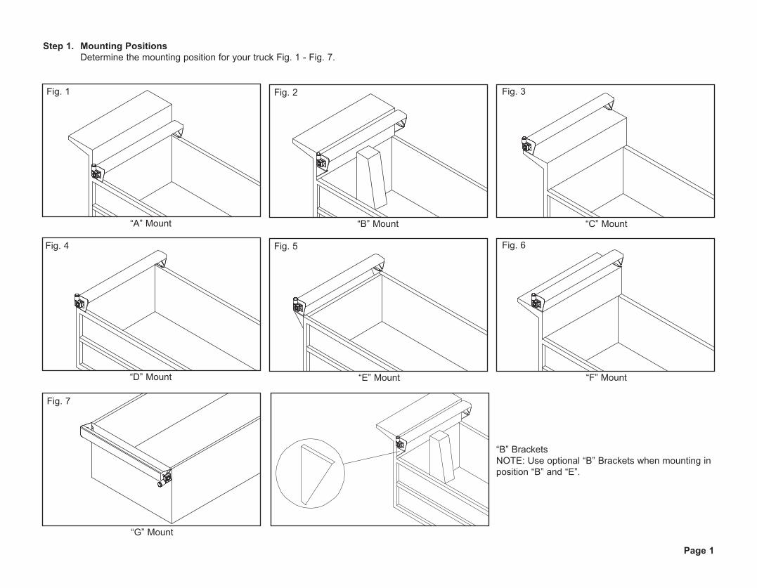
Step 1. Mounting Positions Determine the mounting position for your truck Fig. 1 - Fig. 7.
Fig. 1 Fig. 2 Fig. 3
Fig. 4 Fig. 5
“A” Mount “B” Mount “C” Mount
“E” Mount
“G” Mount
“B” BracketsNOTE: Use optional “B” Brackets when mounting in position “B” and “E”.
Fig. 7
“D” Mount
Fig. 6
“F” Mount

System Assembly Fig. 8A, 8B, 8C, & 8D
Step 2. Weld System To Truck Stitch weld system mounting bar every 6” to truck as shown in (Fig. 12).
Weld Mounting Bar to Truck
Fig. 12
Fig. 8 Fig. 9 Fig. 10 Fig. 11
Open System201-0215
Steel Protector Plus217-0215
Universal Super Shield210-0215
Ultimate Aluminum213-0215
Page 2
Step 3. Tarp Installation Slide Tarp into groove on Roller Tube and center (Fig. 13).
Fig. 13
Note: See Switch Kit for wiring instructions.

Page 3
Fig. 14
CORRECT INCORRECT
Parts: Tie Down Hooks (Steel or Alum.)
Pull Down Hook
The Location Of The Tie Down Hooks Is Critical!
Flip the braided rope over the corner so that the flaps and tie down ropes hang over each side of the box. The number of tie down hooks vary depending on the length of your tarp. One pull down hook is included with your Pulltarp system. If needed. Use the hook to pull the braided rope and flap over the side of the box.
The tie down hooks must be positioned so that:
a. The tie down rope can be reached from the ground.b. The bungee cord has to be stretched to reach the last hook (see step 6).c. The rope has no slack.d. The tie down hooks are level with one another.
To ensure proper hook placement, first duct tape the rope to the box in place of the tie down hooks. Start with hook closest to the cab.
1. Position the first hook 6” (15.24cm) down and 12” (30.48cm) forward (toward the cab) from the first grommet (Fig.14).2. Position 2nd hook straight down from 1st grommet. This hook should be reached from ground (Fig.15).3. Place middle hooks equal distances from grommet (Fig.16). These hooks should be placed at the same height as the second hook.4. Position last hook (closest to the tailgate) below the last grommet at the same height as the others (Fig.17).5. Weld hooks in place.
Step 4. Optional Flap Tarp, Rope and Hook Installation
Fig. 15
Fig. 16
Fig. 17
Page 4
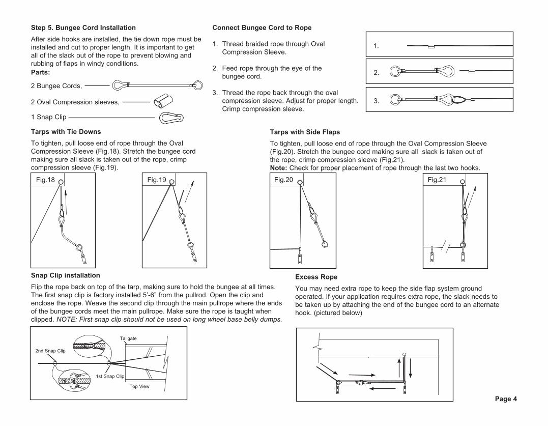
Step 5. Bungee Cord InstallationAfter side hooks are installed, the tie down rope must be installed and cut to proper length. It is important to get all of the slack out of the rope to prevent blowing and rubbing of flaps in windy conditions.Parts:
2 Bungee Cords, 2 Oval Compression sleeves,
1 Snap Clip
Connect Bungee Cord to Rope
1. Thread braided rope through Oval Compression Sleeve.
2. Feed rope through the eye of the bungee cord.
3. Thread the rope back through the oval compression sleeve. Adjust for proper length. Crimp compression sleeve.
Tarps with Tie DownsTo tighten, pull loose end of rope through the Oval Compression Sleeve (Fig.18). Stretch the bungee cord making sure all slack is taken out of the rope, crimp compression sleeve (Fig.19).
Fig.18 Fig.19
Tarps with Side FlapsTo tighten, pull loose end of rope through the Oval Compression Sleeve (Fig.20). Stretch the bungee cord making sure all slack is taken out of the rope, crimp compression sleeve (Fig.21). Note: Check for proper placement of rope through the last two hooks.
Fig.20 Fig.21
Snap Clip installationFlip the rope back on top of the tarp, making sure to hold the bungee at all times. The first snap clip is factory installed 5’-6” from the pullrod. Open the clip and enclose the rope. Weave the second clip through the main pullrope where the ends of the bungee cords meet the main pullrope. Make sure the rope is taught when clipped. NOTE: First snap clip should not be used on long wheel base belly dumps.
Excess RopeYou may need extra rope to keep the side flap system ground operated. If your application requires extra rope, the slack needs to be taken up by attaching the end of the bungee cord to an alternate hook. (pictured below)
2nd Snap Clip
Tailgate
1st Snap Clip
Top View
1.
2.
3.

Page 5
Step 6. Flap/Tie Down Rope Placement and Installation (Fig.22). Step 8. Rope Hook Placement For Steel Arms Weld rope storage hook on the top of the arms approx. 32” apart (Fig.23 A).
Housing
Tarp
Flaps
Bungee
Flap/Tie Down Ropes
Storage Hooks
32”
Arm
Arm
Fig. 23 (A)
Fig. 24
Fig. 22
Hook Placement on Arms
Rope Storage on Arms
Tailgate
32”
Arm
Step 8. Rope Hook Placement For Aluminum Arms Use Self Drilling screws (part #506-9933) to install Hooks (Fig. 23 B)
Fig. 23 (B)
Hook Placement on Arms

Page 6
Wire Pin Connector Spring Tab
Option #1. Plug Assembly - Part # 514-0505Assemble the Quick Disconnect as shown in Fig. 25 and Fig. 26.
Fig. 25
Fig. 26
Option #2. Plug Assembly - Part # 514-0501
Fig. 27

Page 7

NB 3/15/10
STEEL PROTECTOR PLUS HOUSING - 80,84,87,89,93,96,100"lg.501-01XX
1819
20
17
55/16"-18 NYLOC NUT504-310345/16"-18 x 3/4"lg. CARRIAGE BOLT503-3104101/4"-20 NYLOC NUT504-2503151/4" FLAT WASHER USS505-2502101/4"-20 x 3/4"lg. CARRIAGE BOLT503-2505
11111
ELECTRIC END PLATE "N" SYSTEMROLLER DRIVE ALUMINUM END CAPFLANGED END CAPSCREW #8-18 X 3/4" SELF DRILLINGBOLT-IN STUD KIT
(SPECIFY STEEL OR ALUMINUM)
(SPECIFY STEEL OR ALUMINUM)
501-0241501-9915517-0102506-9916501-0633
1RIGHT END PLATE FOR "N" SYSTEM501-0240
1SYSTEM MOUNT BRACKET (RIGHT)501-152X
1SYSTEM MOUNT BRACKET (LEFT)501-152X
1QTY
1ROLLER TUBE - 80,84,87,89,93,96,100"lg.
DESCRIPTIONPART#1
ITEM
4
3
765
2 501-13XX
98
121110
1413
1615
1
1
3315/16"-18 x 1 3/4"lg. HHCS BOLT
5/16"-18 x 3/4 "lg. HHCS BOLT5/16" LOCK WASHER12V DC ELECTRIC MOTOR 1.1HP (217-0215)12V DC ELECTRIC MOTOR 1.3HP (226-0215)PULLTARPS DECAL
503-3108503-3103505-3102517-0906517-0909607-0061
196
1817
11
201
11
5
416
1512
82
12
13
14
127
9
10
163
12
15
15
STEEL PROTECTOR PLUS ELECTRIC ARMS SYSTEM(#217-0215, 226-0215)
Page 8

18
17
2
3
8
6 8
15
1710
16
5
411
12
13
14
9
UNIVERSAL SUPER SHIELD ELECTRIC ARM SYSTEM (#210-0215, 216-0215)
NB-REV: 6/21/10
501-01XX1 9.5" SUPER SHIELD HOUSING - 80,84,87,89,93,96,100"lg. 1501-13XX ROLLER TUBE ASSY - 80,84,87,89,93,96,100"lg.2
31
501-15XX MOUNTING BAR - 40,42,43.5,44.5,46.5,48,50"lg.(SPECIFY STEEL OR ALUMINUM)
(SPECIFY STEEL OR ALUMINUM)
2
501-150X501-1235
16
17
18
6" LARGE MOUNTING BARALUM. ADAPTOR PLATE-SW MOTOR
1
1
503-3108
8
12
607-0061
1413
15
1011
9
503-310567
5
504-3103
45/16"-18 x 1 3/4"lg. HHCS BOLT
PULLTARPS DECAL
5/16"-18 x 1"lg. HHCS BOLT
5/16"-18 NYLOC NUT
13
1
503-3101505-3102
506-9905501-9915517-0102506-9916501-0632
5/16"-18 x 1/2"lg. HHCS BOLT5/16" LOCK WASHER
#10-32 x 1/2"lg. PHILLIPS HEAD PANROLLER DRIVE ALUMINUM END CAPFLANGED END CAPSCREW #8-18 X 3/4" SELF DRILLINGSYSTEM END PLATE STUD KIT
15
41111
2
12
1
517-0906 12V DC ELECTRIC MOTOR 1.1 HP (210-0215)517-0909 12V DC ELECTRIC MOTOR 1.3 HP (216-0215)
1
Part # DESCRIPTION QTY
505-2502 1/4” FLAT WASHER USS
Page 9

18
17
2
3
8
6 8
15
1710
16
5
411
12
13
14
9
UNIVERSAL SUPER SHIELD ELECTRIC ARM SYSTEM (#210-0215, 216-0215)
NB-REV: 6/21/10
501-01XX1 9.5" SUPER SHIELD HOUSING - 80,84,87,89,93,96,100"lg. 1501-13XX ROLLER TUBE ASSY - 80,84,87,89,93,96,100"lg.2
31
501-15XX MOUNTING BAR - 40,42,43.5,44.5,46.5,48,50"lg.(SPECIFY STEEL OR ALUMINUM)
(SPECIFY STEEL OR ALUMINUM)
2
501-150X501-1235
16
17
18
6" LARGE MOUNTING BARALUM. ADAPTOR PLATE-SW MOTOR
1
1
503-3108
8
12
607-0061
1413
15
1011
9
503-310567
5
504-3103
45/16"-18 x 1 3/4"lg. HHCS BOLT
PULLTARPS DECAL
5/16"-18 x 1"lg. HHCS BOLT
5/16"-18 NYLOC NUT
13
1
503-3101505-3102
506-9905501-9915517-0102506-9916501-0632
5/16"-18 x 1/2"lg. HHCS BOLT5/16" LOCK WASHER
#10-32 x 1/2"lg. PHILLIPS HEAD PANROLLER DRIVE ALUMINUM END CAPFLANGED END CAPSCREW #8-18 X 3/4" SELF DRILLINGSYSTEM END PLATE STUD KIT
15
41111
2
12
1
517-0906 12V DC ELECTRIC MOTOR 1.1 HP (210-0215)517-0909 12V DC ELECTRIC MOTOR 1.3 HP (216-0215)
1
Part # DESCRIPTION QTY
505-2502 1/4” FLAT WASHER USS
Page 10