installation instructions and owner's manual · ket, permanently located, manufactured...
TRANSCRIPT

Page 123466-0-0407
INSTALLATION INSTRUCTIONSAND
OWNER'S MANUALUNVENTED
GAS FIREPLACE
MODELS(A)VFD26F(M,P)2(0,1,2,3)(N,W,C)-1(A)VFD26F(M,P)3(0,1,2,3)(N,W,C)-1
(A)VFD26FP3(0,1,2,3)L10-1
EFFECTIVE DATE APRIL 2007
Vent-Free Gas Fireplaces
This appliance may be installed in an aftermar-ket, permanently located, manufactured (mobile) home, where not prohibited by local codes.This appliance is only for use with the type of gas indicated on the rating plate. This appliance is not convertible for use with other gases.
This is an unvented gas-fired heater. It uses air (oxygen) from the room in which it is installed. Provisions for adequate combustion and ventila-tion air must be provided. Refer to page 9.
WATER VAPOR: A BY-PRODUCT OF UNVENTED ROOM HEATERSWater vapor is a by-product of gas combustion. An unvented room heater produces approximate-ly one (1) ounce (30ml) of water for every 1,000 BTU's (.3KW's) of gas input per hour. Refer to page 8.
WARNING: If not installed, operated and main-tained in accordance with the manufacturer's in-structions, this product could expose you to sub-stances in fuel or from fuel combustion which can cause death or serious illness.
— Do not store or use gasoline or other flamma-ble vapors and liquids in the vicinity of this or any other appliance.
— WHAT TO DO IF YOU SMELL GAS • Do not try to light any appliance. • Do not touch any electrical switch; do not
use any phone in your building. • Immediately call your gas supplier from a
neighbor’s phone. Follow the gas suppli-er’s instructions.
• If you cannot reach your gas supplier, call the fire department.
— Installation and service must be performed by a qualified installer, service agency or the gas supplier.
WARNING: If the information in these instruc-tions are not followed exactly, a fire or explosion may result causing property damage, personal injury or loss of life.
Installer: Leave this manual with the appli-ance.
Consumer: Retain this manual for future refer-ence.

Page 2 23466-0-0407
SECTION PAGE
IMPORTANT SAFETY INFORMATION ..................................................................................... 3SAFETY INFORMATION FOR USERS OF LP-GAS ................................................................. 4INTRODUCTION .......................................................................................................................... 5BUILT-IN FIREPLACE INSTALLATION .................................................................................... 6FIREPLACE DIMENSIONS ......................................................................................................... 7WATER VAPOR: A BY-PRODUCT OF UNVENTED ROOM HEATERS .................................. 8SPECIFICATIONS ......................................................................................................................... 8PROVISIONS FOR ADEQUATE COMBUSTION & VENTILATION AIR ..........................9-10GAS SUPPLY ............................................................................................................................... 11CLEARANCES ............................................................................................................................ 12COMBUSTIBLE MATERIAL ..................................................................................................... 12INSTALLATION OF FIREPLACE AND MANTEL .............................................................13-14LOG PLACEMENT ..................................................................................................................... 15PLACEMENT OF GLOWING EMBERS (ROCK WOOL) ....................................................... 16OPERATION INSTRUCTIONS/FLAME APPEARANCE ........................................................ 16(A)VFD26FP3L10 LIGHTING INSTRUCTIONS ...................................................................... 17(A)VFD26F(M,P)3 LIGHTING INSTRUCTIONS ..................................................................... 18(A)VFD26F(M,P)2 LIGHTING INSTRUCTIONS ..................................................................... 19PILOT FLAME CHARACTERISTICS ..................................................................................20-21MAIN BURNER AND THERMOSTAT OPERATION .............................................................. 21OUTER TRIM INSTRUCTIONS ................................................................................................ 22HOOD INSTRUCTIONS ............................................................................................................. 22(A)VFD26F3 WIRING ................................................................................................................ 23JUNCTION BOX WIRING INSTALLATION INSTRUCTIONS .............................................. 24TROUBLESHOOTING ............................................................................................................... 25PARTS LIST ................................................................................................................................. 26PARTS VIEW ............................................................................................................................... 27FBBX BLOWER KIT EXTENSION INSTALLATION INSTRUCTIONS ..........................28-29FBB4 OPTIONAL VARIABLE SPEED BLOWER .................................................................... 29FPP26E OPTIONAL BRICK LINER KIT INSTALLATION INSTRUCTIONS ....................... 30HOW TO ORDER REPAIR PARTS ............................................................................................ 31SERVICE NOTES ........................................................................................................................ 31
TABLE OF CONTENTS
Page 323466-0-0407
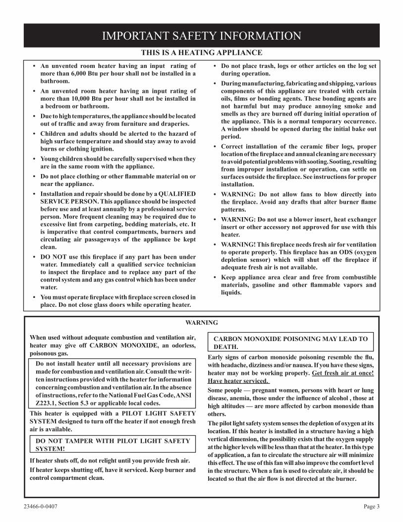
When used without adequate combustion and ventilation air, heater may give off CARBON MONOXIDE, an odorless, poisonous gas.
Do not install heater until all necessary provisions are made for combustion and ventilation air. Consult the writ-ten instructions provided with the heater for information concerning combustion and ventilation air. In the absence of instructions, refer to the National Fuel Gas Code, ANSI Z223.1, Section 5.3 or applicable local codes.
This heater is equipped with a PILOT LIGHT SAFETY SYSTEM designed to turn off the heater if not enough fresh air is available.
DO NOT TAMPER WITH PILOT LIGHT SAFETY SYSTEM!
If heater shuts off, do not relight until you provide fresh air.If heater keeps shutting off, have it serviced. Keep burner and control compartment clean.
CARBON MONOXIDE POISONING MAY LEAD TO DEATH.
Early signs of carbon monoxide poisoning resemble the flu, with headache, dizziness and/or nausea. If you have these signs, heater may not be working properly. Get fresh air at once! Have heater serviced. Some people — pregnant women, persons with heart or lung disease, anemia, those under the influence of alcohol , those at high altitudes — are more affected by carbon monoxide than others.The pilot light safety system senses the depletion of oxygen at its location. If this heater is installed in a structure having a high vertical dimension, the possibility exists that the oxygen supply at the higher levels will be less than that at the heater. In this type of application, a fan to circulate the structure air will minimize this effect. The use of this fan will also improve the comfort level in the structure. When a fan is used to circulate air, it should be located so that the air flow is not directed at the burner.
WARNING
• An unvented room heater having an input rating of more than 6,000 Btu per hour shall not be installed in a bathroom.
• An unvented room heater having an input rating of more than 10,000 Btu per hour shall not be installed in a bedroom or bathroom.
• Due to high temperatures, the appliance should be located out of traffic and away from furniture and draperies.
• Children and adults should be alerted to the hazard of high surface temperature and should stay away to avoid burns or clothing ignition.
• Young children should be carefully supervised when they are in the same room with the appliance.
• Do not place clothing or other flammable material on or near the appliance.
• Installation and repair should be done by a QUALIFIED SERVICE PERSON. This appliance should be inspected before use and at least annually by a professional service person. More frequent cleaning may be required due to excessive lint from carpeting, bedding materials, etc. It is imperative that control compartments, burners and circulating air passageways of the appliance be kept clean.
• DO NOT use this fireplace if any part has been under water. Immediately call a qualified service technician to inspect the fireplace and to replace any part of the control system and any gas control which has been under water.
• You must operate fireplace with fireplace screen closed in place. Do not close glass doors while operating heater.
• Do not place trash, logs or other articles on the log set during operation.
• During manufacturing, fabricating and shipping, various components of this appliance are treated with certain oils, films or bonding agents. These bonding agents are not harmful but may produce annoying smoke and smells as they are burned off during initial operation of the appliance. This is a normal temporary occurrence. A window should be opened during the initial bake out period.
• Correct installation of the ceramic fiber logs, proper location of the fireplace and annual cleaning are necessary to avoid potential problems with sooting. Sooting, resulting from improper installation or operation, can settle on surfaces outside the fireplace. See instructions for proper installation.
• WARNING: Do not allow fans to blow directly into the fireplace. Avoid any drafts that alter burner flame patterns.
• WARNING: Do not use a blower insert, heat exchanger insert or other accessory not approved for use with this heater.
• WARNING! This fireplace needs fresh air for ventilation to operate properly. This fireplace has an ODS (oxygen depletion sensor) which will shut off the fireplace if adequate fresh air is not available.
• Keep appliance area clear and free from combustible materials, gasoline and other flammable vapors and liquids.
THIS IS A HEATING APPLIANCE
IMPORTANT SAFETY INFORMATION

Page 4 23466-0-0407
Some people cannot smell well. Some people cannot smell the odor of the chemical put into the gas. You must find out if you can smell the odorant in propane. Smoking can decrease your ability to smell. Being around an odor for a time can affect your sensitivity or ability to detect that odor. Sometimes other odors in the area mask the gas odor. People may not smell the gas odor or their minds are on something else. Thinking about smelling a gas odor can make it easier to smell.
The odorant in LP-gas is colorless, and it can fade under some circumstances. For example, if there is an underground leak, the movement of the gas through soil can filter the odorant. Odorants in LP-Gas also are subject to oxidation. This fading can occur if
by point with the members of your household. Someday when there may not be a minute to lose, everyone's safety will depend on knowing exactly what to do. If, after read-ing the following information, you feel you still need more information, please contact your gas supplier.
Propane (LP-Gas) is a flammable gas which can cause fires and explosions. In its natural state, propane is odorless and colorless. You may not know all the following safety precau-tions which can protect both you and your family from an accident. Read them carefully now, then review them point
there is rust inside the storage tank or in iron gas pipes.
The odorant in escaped gas can adsorb or absorb onto or into walls, masonry and other materials and fabrics in a room. That will take some of the odorant out of the gas, reducing its odor intensity.
LP-Gas may stratify in a closed area, and the odor intensity could vary at different levels. Since it is heavier than air, there may be more odor at lower levels. Always be sensitive to the slightest gas odor. If you detect any odor, treat it as a serious leak. Immediately go into action as instructed earlier.
• Learn to recognize the odor of LP-gas. Your local LP-Gas Dealer can give you a "Scratch and Sniff" pamphlet. Use it to find out what the propane odor smells like. If you suspect that your LP-Gas has a weak or abnormal odor, call your LP-Gas Dealer.
• If you are not qualified, do not light pilot lights, perform service, or make adjustments to appliances on the LP-Gas system. If you are qualified, consciously think about the odor of LP-Gas prior to and while lighting pilot lights or performing service or making adjustments.
• Sometimes a basement or a closed-up house has a musty smell that can cover up the LP-Gas odor. Do not try to light pilot lights, perform service, or make adjustments in an area where the conditions are such that you may not detect the odor if there has been a leak of LP-Gas.
• Odor fade, due to oxidation by rust or adsorption on walls of new cylinders and tanks, is possible. Therefore, people should be particularly alert and careful when new tanks or cylinders are placed in service. Odor fade can occur in new tanks, or reinstalled old tanks, if they are filled and allowed
to set too long before refilling. Cylinders and tanks which have been out of service for a time may develop internal rust which will cause odor fade. If such conditions are suspected to exist, a periodic sniff test of the gas is advisable. If you have any question about the gas odor, call your LP-gas dealer. A periodic sniff test of the LP-gas is a good safety measure under any condition.
• If, at any time, you do not smell the LP-Gas odorant and you think you should, assume you have a leak. Then take the same immediate action recommended above for the occasion when you do detect the odorized LP-Gas.
• If you experience a complete "gas out," (the container is un-der no vapor pressure), turn the tank valve off immediately. If the container valve is left on, the container may draw in some air through openings such as pilot light orifices. If this occurs, some new internal rusting could occur. If the valve is left open, then treat the container as a new tank. Always be sure your container is under vapor pressure by turning it off at the container before it goes completely empty or having it refilled before it is completely empty.
• Do not operate electric switches, light matches, use your phone. Do not do anything that could ignite the gas.
• Get everyone out of the building, vehicle, trailer, or area. Do that IMMEDIATELY.
• Close all gas tank or cylinder supply valves.• LP-Gas is heavier than air and may settle in low areas such
as basements. When you have reason to suspect a gas leak, keep out of basements and other low areas. Stay out until firefighters declare them to be safe.
• Use your neighbor's phone and call a trained LP-Gas service person and the fire department. Even though you may not continue to smell gas, do not turn on the gas again. Do not re-enter the building, vehicle, trailer, or area.
• Finally, let the service man and firefighters check for escaped gas. Have them air out the area before you return. Properly trained LP-Gas service people should repair the leak, then check and relight the gas appliance for you.
SOME POINTS TO REMEMBER
NO ODOR DETECTED - ODOR FADE
LP-GAS WARNING ODORIf a gas leak happens, you should be able to smell the gas because of the odorant put in the LP-Gas.
That's your signal to go into immediate action!
SAFETY INFORMATION FOR USERS OF LP-GAS

Page 523466-0-0407
instructions.Any alteration of the original design, installed other than as shown in these instructions or use with a type of gas not shown on the rating plate is the responsibility of the person and com-pany making the change.ImportantAll correspondence should refer to complete Model Number, Serial Number and type of gas.Attention: During initial use of ceramic log you will detect an odor as the ceramic log is cured. Also, during the curing process the ceramic log will burn with a yellow flame.Notice: During initial firing of this unit, its paint will bake out, and smoke will occur. To prevent triggering of smoke alarms, ventilate the room in which the unit is installed.Installation on Rugs and TileIf this appliance is installed directly on carpeting, tile or other combustible material other than wood flooring the appliance shall be installed on a metal or wood panel extending the full width and depth of the appliance. The base referred to above does not mean the fire-proof base as used on wood stoves. The protection is for rugs that are extremely thick and light colored tile.
Solid-fuels shall not be burned in a masonry or UL 127 factory-built fireplace in which an unvented room heater is installed.
Qualified Installing AgencyInstallation and replacement of gas piping, gas utilization equip-ment or accessories and repair and servicing of equipment shall be performed only by a qualified agency. The term "qualified agency" means any individual, firm, corporation or company which either in person or through a representative is engaged in and is responsible for (a) the installation or replacement of gas piping or (b) the connection, installation, repair or servicing of equipment, who is experienced in such work, familiar with all precautions re-quired and has complied with all the requirements of the authority having jurisdiction.
State of Massachusetts: The installation must be made by a licensed plumber or gas fitter in the Commonwealth of Mas-sachusetts.Sellers of unvented propane or natural gas-fired supplemental room heaters shall provide to each purchaser a copy of 527 CMR 30 upon sale of the unit.In the State of Massachusetts, unvented propane and natural gas-fired space heaters shall be prohibited in bedrooms and bathrooms.
The installation must conform with local codes or, in the absence of local codes, with the National Fuel Gas Code, ANSI Z223.1.**Available from the American National Standards Institute, Inc. 1430 Broadway, New York, N.Y. 10018.
High AltitudesFor altitudes/elevations above 2,000 feet (610m), ratings should be reduced at the rate of 4 percent for each 1,000 feet (305m) above sea level. Contact the manufacturer or your gas company before changing spud/orifice size.
WARNING: Failure to keep the primary air opening(s) of the burner(s) clean may result in sooting and property damage.
Instructions to Installer1. Installer must leave instruction manual with owner after
installation.2. Installer must have owner fill out and mail warranty card supplied
with unvented room heater.3. Installer should show owner how to start and operate unvented
room heater.
Always consult your local Building Department regarding regu-lations, codes or ordinances which apply to the installation of an unvented room heater.This appliance may be installed in an aftermarket* manufactured (mobile) home, where not prohibited by state or local codes.
*Aftermarket: Completion of sale, not for purpose of resale, from the manufacturer.
This appliance is only for use with the type of gas indicated on the rating plate. This appliance is not convertible for use with other gases.
Well Head Gas InstallationsSome natural gas utilities use "well head" gas. This may affect the Btu output of the unit. Contact the gas company for the heating value. Contact the manufacturer or your gas company before changing spud/orifice size.
WARNING: ANY CHANGE TO THIS HEATER OR ITS CONTROLS CAN BE DANGEROUS. Improper installation or use of the heater can cause seri-ous injury or death from fire, burns, explosion or carbon monoxide poisoning.
OperationThis unvented fireplace requires no outside venting. This unvented fireplace is designed for vent-free operation with flue damper closed. State and local codes in some areas prohibit the use of unvented fireplace.
(A)VFD26F(M,P)3, Millivolt controlsThe valve regulator controls the burner pressure which should be checked at the pressure test point. Turn captured screw counter clockwise 2 or 3 turns and then place tubing to pressure gauge over test point (Use test point “A” closest to control knob). After taking pressure reading, be sure and turn captured screw clockwise firmly to re-seal. Do not over torque. Check for gas leaks.
Millivolt System, (A)VFD26F(M,P)3When you ignite the pilot, the thermocouple produces millivolts (electrical current) which energizes the magnet in the gas valve. After 30 seconds to 1 minute time period you can release the gas control knob and the pilot will stay ON. Allow your pilot flame to operate an additional one (1) to two (2) minutes before you turn the gas control knob from the PILOT position to the ON position. This time period allows the millivolts (electrical current) to build-up to a sufficient level allowing the gas control to operate properly.
WARNING: This appliance is equipped for (natural gas or propane) gas. Field conversion is not permitted.
General InformationThis series is design certified in accordance with American National Standard Z21.11.2 by the Canadian Standards Association as an Unvented Room Heater and should be installed according to these
INTRODUCTION
Page 6 23466-0-0407
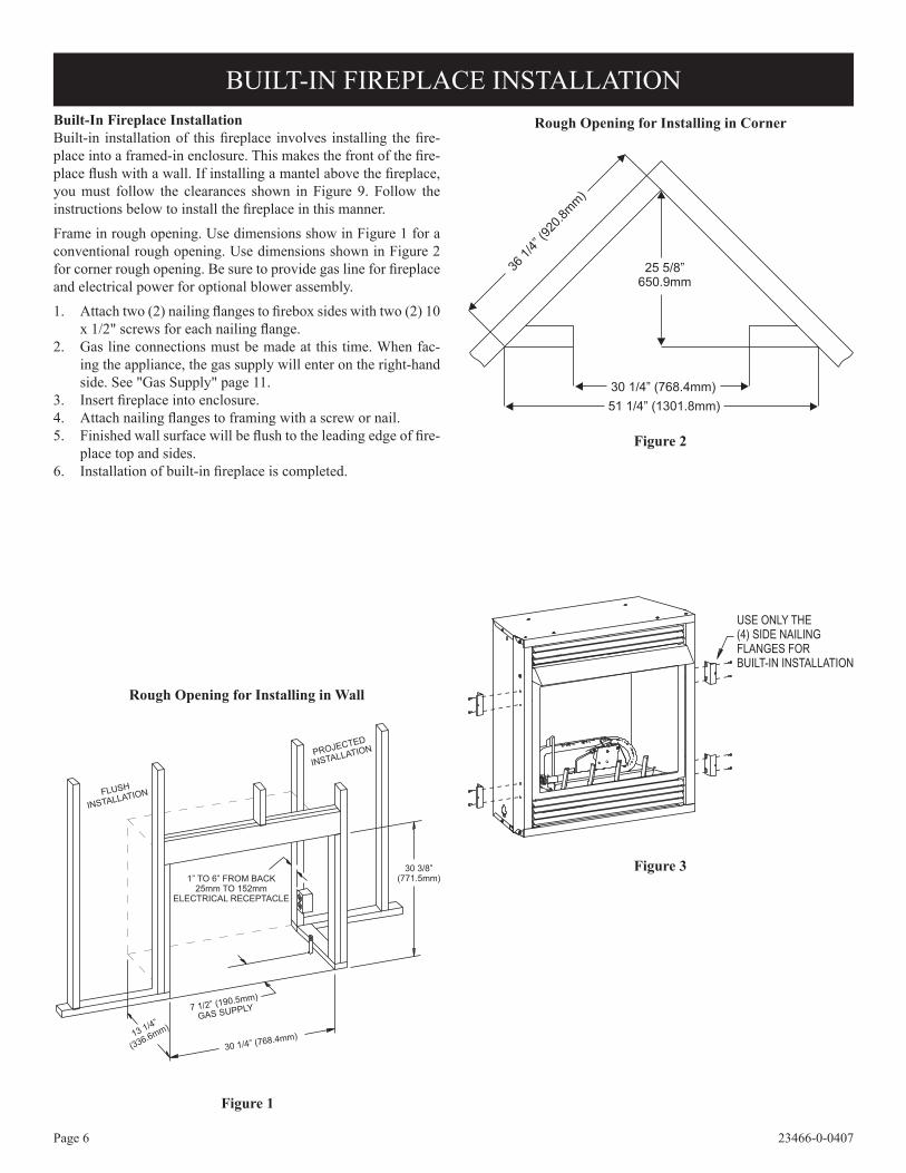
BUILT-IN FIREPLACE INSTALLATIONBuilt-In Fireplace InstallationBuilt-in installation of this fireplace involves installing the fire-place into a framed-in enclosure. This makes the front of the fire-place flush with a wall. If installing a mantel above the fireplace, you must follow the clearances shown in Figure 9. Follow the instructions below to install the fireplace in this manner.
Frame in rough opening. Use dimensions show in Figure 1 for a conventional rough opening. Use dimensions shown in Figure 2 for corner rough opening. Be sure to provide gas line for fireplace and electrical power for optional blower assembly.
1. Attach two (2) nailing flanges to firebox sides with two (2) 10 x 1/2" screws for each nailing flange.
2. Gas line connections must be made at this time. When fac-ing the appliance, the gas supply will enter on the right-hand side. See "Gas Supply" page 11.
3. Insert fireplace into enclosure.4. Attach nailing flanges to framing with a screw or nail.5. Finished wall surface will be flush to the leading edge of fire-
place top and sides.6. Installation of built-in fireplace is completed.
Figure 2
Figure 3
Figure 1
Rough Opening for Installing in Wall
Rough Opening for Installing in Corner
Page 723466-0-0407
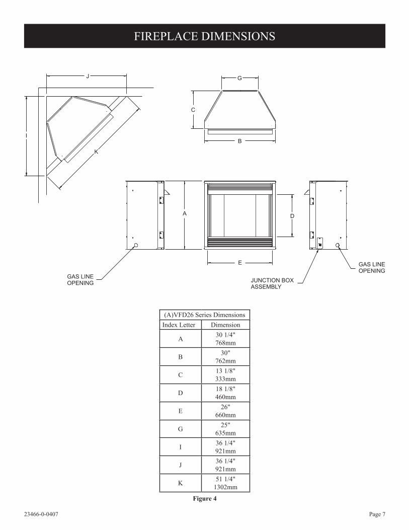
FIREPLACE DIMENSIONS
GAS LINEOPENING JUNCTION BOX
ASSEMBLY
GAS LINEOPENING
J
I
K
B
C
G
A D
E
Figure 4
(A)VFD26 Series DimensionsIndex Letter Dimension
A 30 1/4"768mm
B 30"762mm
C 13 1/8"333mm
D 18 1/8"460mm
E 26"660mm
G 25"635mm
I 36 1/4"921mm
J 36 1/4"921mm
K 51 1/4"1302mm
Page 8 23466-0-0407
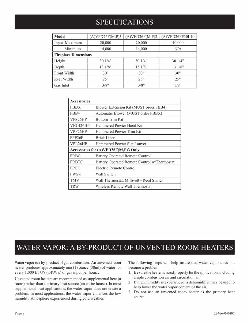
SPECIFICATIONS
Model (A)VFD26F(M,P)3 (A)VFD26F(M,P)2 (A)VFD26FP30L10Input Maximum 20,000 20,000 10,000 Minimum 14,000 14,000 N/AFireplace DimensionsHeight 30 1/4" 30 1/4" 30 1/4"Depth 13 1/8" 13 1/8" 13 1/8"Front Width 30" 30" 30"Rear Width 25" 25" 25"Gas Inlet 3/8" 3/8" 3/8"
AccessoriesFBBX Blower Extension Kit (MUST order FBB4)FBB4 Automatic Blower (MUST order FBBX)VPS26HP Bottom Trim KitVF2H26HP Hammered Pewter Hood KitVPF26HP Hammered Pewter Trim KitFPP26E Brick LinerVPL26HP Hammered Pewter Slat LouverAccessories for (A)VFD26F(M,P)3 OnlyFRBC Battery Operated Remote ControlFRBTC Battery Operated Remote Control w/ThermostatFREC Electric Remote ControlFWS-1 Wall SwitchTMV Wall Thermostat, Millivolt - Reed SwitchTRW Wireless Remote Wall Thermostat
Water vapor is a by-product of gas combustion. An unvented room heater produces approximately one (1) ounce (30ml) of water for every 1,000 BTU's (.3KW's) of gas input per hour. . Unvented room heaters are recommended as supplemental heat (a room) rather than a primary heat source (an entire house). In most supplemental heat applications, the water vapor does not create a problem. In most applications, the water vapor enhances the low humidity atmosphere experienced during cold weather.
The following steps will help insure that water vapor does not become a problem. 1. Be sure the heater is sized properly for the application, including
ample combustion air and circulation air.2. If high humidity is experienced, a dehumidifier may be used to
help lower the water vapor content of the air.3. Do not use an unvented room heater as the primary heat
source.
WATER VAPOR: A BY-PRODUCT OF UNVENTED ROOM HEATERS

Page 923466-0-0407
3. Add the BTU/Hr of all fuel burning appliances in the space. Vent-free heater BTU/Hr Gas water heater BTU/Hr Gas furnace BTU/Hr Vented gas heater BTU/Hr Gas fireplace logs BTU/Hr Other gas appliances* + BTU/Hr Total = BTU/Hr
Example: Vented gas heater 20,000 BTU/Hr Vent-free heater + 18,000 BTU/Hr Total = 38,000 BTU/Hr*Do not include direct-vent gas appliances. Direct vent draws combustion air from the outdoors and vents to the outdoors.
4. Compare the maximum BTU/Hr the space can support with the actual amount of BTU/Hr used.
BTU/Hr (maximum the space can support) BTU/Hr (actual amount of BTU/Hr used) Example: 25,600 BTU/Hr (maximum the space can support) 38,000 BTU/Hr (actual amount of BTU/Hr used)
Warning: If the area in which the heater may be operated is smaller than that defined as an unconfined space or if the building is of unusually tight construction, provide adequate combustion and ventilation air by one of the methods described in the National Fuel Gas Code, ANSI Z223.1, Section 5.3 or applicable local codes.The space in the above example is a confined space because the actual BTU/Hr used is more than the maximum BTU/HR the space can support. You must provide additional fresh air. Your options are as follows:A. Rework worksheet, adding the space of an adjoining room. If
the extra space provides an unconfined space, remove door to adjoining room or add ventilation grills between rooms. See Ventilation Air From Inside Building.
B. Vent room directly to the outdoors. See Ventilation Air From Outdoors.
C. Install a lower BTU/Hr heater, if lower BTU/Hr size makes room unconfined.
If the actual BTU/Hr used is less than the maximum BTU/Hr the space can support, the space is an unconfined space. You will need no additional fresh air ventilation.
WARNING: You must provide additional ventilation air in a confined space.
This heater shall not be installed in a confined space or unusually tight construction unless provisions are provided for adequate combustion and ventilation air.The National Fuel Gas Code defines a confined space as a space whose volume is less than 50 cubic feet per 1,000 Btu per hour (4.8m3 per kw) of the aggregate input rating of all appliances installed in that space and an unconfined space as a space whose volume is not less than 50 cubic feet per 1,000 Btu per hour (4.8 m3 per kw) of the aggregate input rating of all appliances installed in that space. Rooms communicating directly with the space in which the appliances are installed, through openings not furnished with doors, are considered a part of the unconfined space.Unusually Tight ConstructionThe air that leaks around doors and windows may provide enough fresh air for combustion and ventilation. However, in buildings of unusually tight construction, you must provide additional fresh air. Unusually tight construction is defined as construction
where:a. Walls and ceilings exposed to the outside atmosphere have
a continuous water vapor retarder with a rating of one perm or less with openings gasketed or sealed, and
b. Weatherstripping has been added on openable windows and doors, and
c. Caulking or sealants are applied to areas such as joints around window and door frames, between sole plates and floors, between wall-ceiling joints, between wall panels, at penetrations for plumbing, electrical, and gas lines, and at other openings.
If your home meets all of the three criteria above, you must provide additional fresh air. See “Ventilation Air From Outdoors,” page 10.
Determining if You Have a Confined or Unconfined SpaceUse this worksheet to determine if you have a confined or unconfined space. Space: Includes the room in which you will install heater plus any adjoining rooms with doorless passageways or ventilation grills between the rooms.1. Determine the volume of the space (length x width x height). Length x Width x Height = cu. ft. (volume of
space)Example: Space size 16 ft. (length) x 10 ft. (width) x 8 ft. (ceiling
height) = 1,280 cu. ft. (volume of space) If additional ventilation to adjoining room is supplied with grills
or openings, add the volume of these rooms to the total volume of the space.
2. Divide the space volume by 50 cubic feet to determine the maximum BTU/Hr the space can support.
(volume of space) ÷ 50 cu. ft. = (maximum BTU/Hr the space can support)Example: 1,280 cu. ft. (volume of space) ÷ 50 cu. ft. = 25.6 or
25,600 (maximum BTU/Hr the space can support)
PROVISIONS FOR ADEQUATE COMBUSTION & VENTILATION AIR
Page 10 23466-0-0407
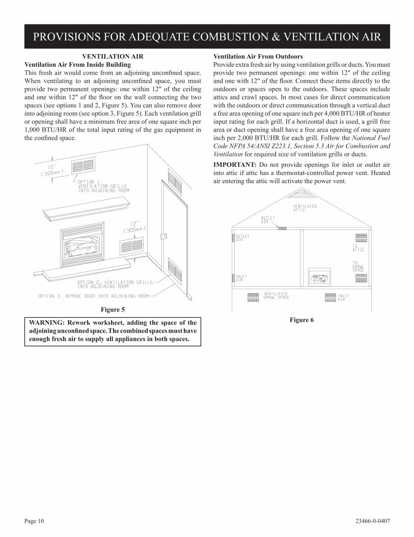
VENTILATION AIRVentilation Air From Inside BuildingThis fresh air would come from an adjoining unconfined space. When ventilating to an adjoining unconfined space, you must provide two permanent openings: one within 12" of the ceiling and one within 12" of the floor on the wall connecting the two spaces (see options 1 and 2, Figure 5). You can also remove door into adjoining room (see option 3, Figure 5). Each ventilation grill or opening shall have a minimum free area of one square inch per 1,000 BTU/HR of the total input rating of the gas equipment in the confined space.
Figure 5
WARNING: Rework worksheet, adding the space of the adjoining unconfined space. The combined spaces must have enough fresh air to supply all appliances in both spaces.
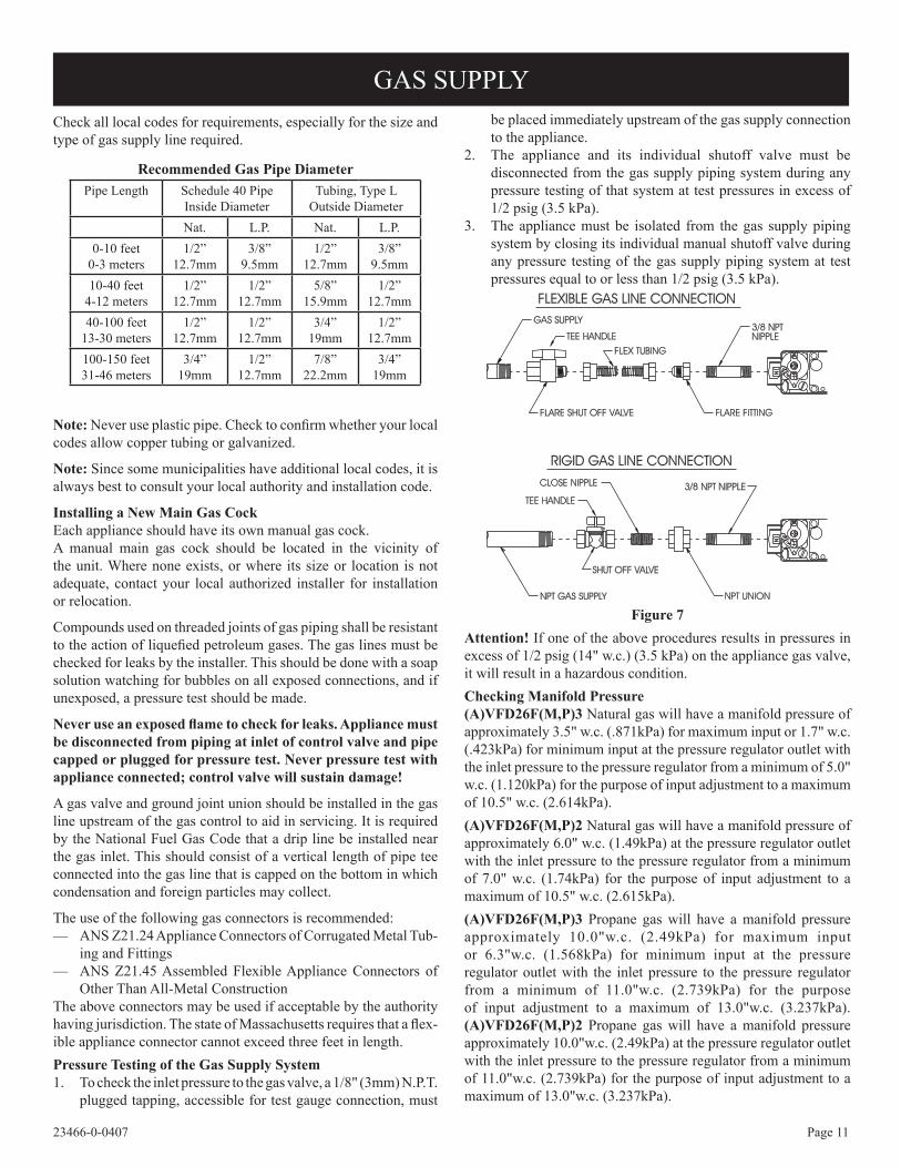
Ventilation Air From OutdoorsProvide extra fresh air by using ventilation grills or ducts. You must provide two permanent openings: one within 12" of the ceiling and one with 12" of the floor. Connect these items directly to the outdoors or spaces open to the outdoors. These spaces include attics and crawl spaces. In most cases for direct communication with the outdoors or direct communication through a vertical duct a free area opening of one square inch per 4,000 BTU/HR of heater input rating for each grill. If a horizontal duct is used, a grill free area or duct opening shall have a free area opening of one square inch per 2,000 BTU/HR for each grill. Follow the National Fuel Code NFPA 54/ANSI Z223.1, Section 5.3 Air for Combustion and Ventilation for required size of ventilation grills or ducts.IMPORTANT: Do not provide openings for inlet or outlet air into attic if attic has a thermostat-controlled power vent. Heated air entering the attic will activate the power vent.
Figure 6
PROVISIONS FOR ADEQUATE COMBUSTION & VENTILATION AIR
Page 1123466-0-0407
Check all local codes for requirements, especially for the size and type of gas supply line required.
Recommended Gas Pipe DiameterPipe Length Schedule 40 Pipe
Inside DiameterTubing, Type L
Outside DiameterNat. L.P. Nat. L.P.
0-10 feet0-3 meters
1/2”12.7mm
3/8”9.5mm
1/2”12.7mm
3/8”9.5mm
10-40 feet4-12 meters
1/2”12.7mm
1/2”12.7mm
5/8”15.9mm
1/2”12.7mm
40-100 feet13-30 meters
1/2”12.7mm
1/2”12.7mm
3/4”19mm
1/2”12.7mm
100-150 feet31-46 meters
3/4”19mm
1/2”12.7mm
7/8”22.2mm
3/4”19mm
Note: Never use plastic pipe. Check to confirm whether your local codes allow copper tubing or galvanized.
Note: Since some municipalities have additional local codes, it is always best to consult your local authority and installation code.
Installing a New Main Gas Cock Each appliance should have its own manual gas cock.A manual main gas cock should be located in the vicinity of the unit. Where none exists, or where its size or location is not adequate, contact your local authorized installer for installation or relocation.
Compounds used on threaded joints of gas piping shall be resistant to the action of liquefied petroleum gases. The gas lines must be checked for leaks by the installer. This should be done with a soap solution watching for bubbles on all exposed connections, and if unexposed, a pressure test should be made.
Never use an exposed flame to check for leaks. Appliance must be disconnected from piping at inlet of control valve and pipe capped or plugged for pressure test. Never pressure test with appliance connected; control valve will sustain damage!
A gas valve and ground joint union should be installed in the gas line upstream of the gas control to aid in servicing. It is required by the National Fuel Gas Code that a drip line be installed near the gas inlet. This should consist of a vertical length of pipe tee connected into the gas line that is capped on the bottom in which condensation and foreign particles may collect.
The use of the following gas connectors is recommended:— ANS Z21.24 Appliance Connectors of Corrugated Metal Tub-
ing and Fittings— ANS Z21.45 Assembled Flexible Appliance Connectors of
Other Than All-Metal ConstructionThe above connectors may be used if acceptable by the authority having jurisdiction. The state of Massachusetts requires that a flex-ible appliance connector cannot exceed three feet in length.Pressure Testing of the Gas Supply System1. To check the inlet pressure to the gas valve, a 1/8" (3mm) N.P.T.
plugged tapping, accessible for test gauge connection, must
be placed immediately upstream of the gas supply connection to the appliance.
2. The appliance and its individual shutoff valve must be disconnected from the gas supply piping system during any pressure testing of that system at test pressures in excess of 1/2 psig (3.5 kPa).
3. The appliance must be isolated from the gas supply piping system by closing its individual manual shutoff valve during any pressure testing of the gas supply piping system at test pressures equal to or less than 1/2 psig (3.5 kPa).
Figure 7Attention! If one of the above procedures results in pressures in excess of 1/2 psig (14" w.c.) (3.5 kPa) on the appliance gas valve, it will result in a hazardous condition.Checking Manifold Pressure(A)VFD26F(M,P)3 Natural gas will have a manifold pressure of approximately 3.5" w.c. (.871kPa) for maximum input or 1.7" w.c. (.423kPa) for minimum input at the pressure regulator outlet with the inlet pressure to the pressure regulator from a minimum of 5.0" w.c. (1.120kPa) for the purpose of input adjustment to a maximum of 10.5" w.c. (2.614kPa). (A)VFD26F(M,P)2 Natural gas will have a manifold pressure of approximately 6.0" w.c. (1.49kPa) at the pressure regulator outlet with the inlet pressure to the pressure regulator from a minimum of 7.0" w.c. (1.74kPa) for the purpose of input adjustment to a maximum of 10.5" w.c. (2.615kPa). (A)VFD26F(M,P)3 Propane gas will have a manifold pressure approximately 10.0"w.c. (2.49kPa) for maximum input or 6.3"w.c. (1.568kPa) for minimum input at the pressure regulator outlet with the inlet pressure to the pressure regulator from a minimum of 11.0"w.c. (2.739kPa) for the purpose of input adjustment to a maximum of 13.0"w.c. (3.237kPa). (A)VFD26F(M,P)2 Propane gas will have a manifold pressure approximately 10.0"w.c. (2.49kPa) at the pressure regulator outlet with the inlet pressure to the pressure regulator from a minimum of 11.0"w.c. (2.739kPa) for the purpose of input adjustment to a maximum of 13.0"w.c. (3.237kPa).
GAS SUPPLY
Page 12 23466-0-0407
Minimum Wall and Ceiling Clearances
36”
(91.44 cm)
2” (5.08 cm)
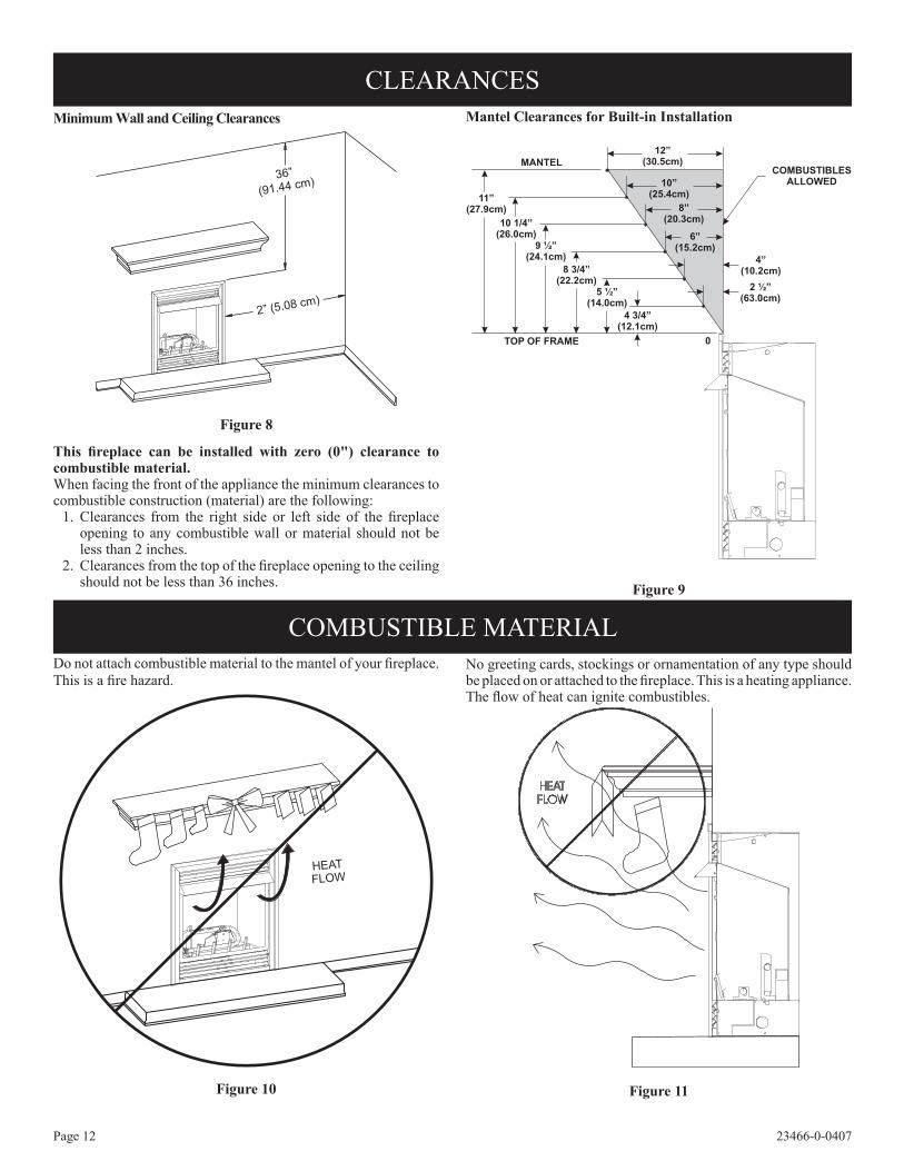
Figure 8
This fireplace can be installed with zero (0") clearance to combustible material.When facing the front of the appliance the minimum clearances to combustible construction (material) are the following: 1. Clearances from the right side or left side of the fireplace
opening to any combustible wall or material should not be less than 2 inches.
2. Clearances from the top of the fireplace opening to the ceiling should not be less than 36 inches.
Mantel Clearances for Built-in Installation
Figure 9
Do not attach combustible material to the mantel of your fireplace. This is a fire hazard.
HEATFLOW
Figure 10
No greeting cards, stockings or ornamentation of any type should be placed on or attached to the fireplace. This is a heating appliance. The flow of heat can ignite combustibles.
Figure 11
CLEARANCES
COMBUSTIBLE MATERIAL
COMBUSTIBLESALLOWED
4”(10.2cm)
5 ½”(14.0cm)
2 ½”(63.0cm)
4 3/4”(12.1cm)
6”(15.2cm)
8 3/4”(22.2cm)
8”(20.3cm)
9 ½”(24.1cm)
10”(25.4cm)
10 1/4”(26.0cm)
12”(30.5cm)
11”(27.9cm)
TOP OF FRAME 0
MANTEL
Page 1323466-0-0407
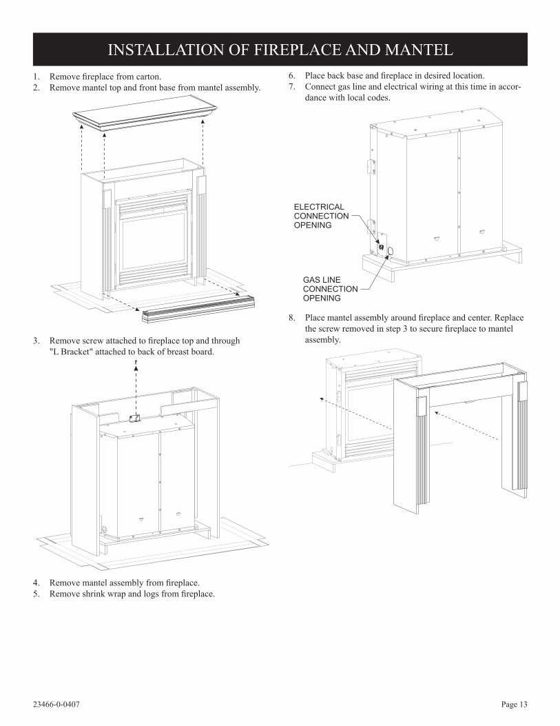
1. Remove fireplace from carton.2. Remove mantel top and front base from mantel assembly.
3. Remove screw attached to fireplace top and through "L Bracket" attached to back of breast board.
4. Remove mantel assembly from fireplace.5. Remove shrink wrap and logs from fireplace.
6. Place back base and fireplace in desired location. 7. Connect gas line and electrical wiring at this time in accor-
dance with local codes.
8. Place mantel assembly around fireplace and center. Replace the screw removed in step 3 to secure fireplace to mantel assembly.
ELECTRICALCONNECTIONOPENING
GAS LINECONNECTIONOPENING
INSTALLATION OF FIREPLACE AND MANTEL
Page 14 23466-0-0407
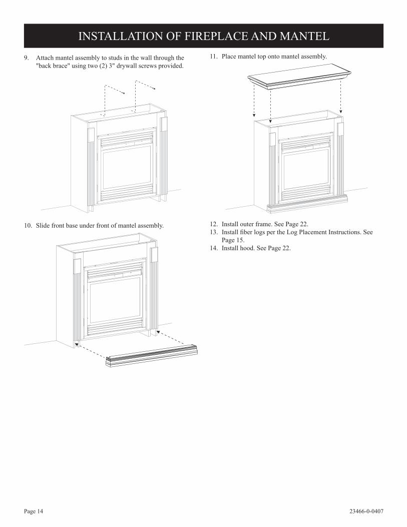
11. Place mantel top onto mantel assembly.
12. Install outer frame. See Page 22.13. Install fiber logs per the Log Placement Instructions. See
Page 15.14. Install hood. See Page 22.
9. Attach mantel assembly to studs in the wall through the "back brace" using two (2) 3" drywall screws provided.
10. Slide front base under front of mantel assembly.
INSTALLATION OF FIREPLACE AND MANTEL

Page 1523466-0-0407
LOG PLACEMENT 1. Place front logs (#1 and #2) between front grate flange and
main burner. Align notches on front logs with locator tabs in base.
2. Place middle log (#3) between front and rear loop of burner. Note: Do not place log on top of pilot assembly. 3. Place rear log (#4) on rear log shelf. Bottom flange of log must
be placed between the log shelf and burner tube. 4. This step is optional for (A)VFD26FP3L10 log sets. Place
front twig (#5) onto (#1) log and flat area on (#3) log. The bottom of the front twig is to be placed behind the grate tang that is second from the left.
Attention: Do not use Figures 12 and 13 to order logs. Refer to Page 26, Parts list and Page 27, Parts View to order logs.
Refer to Figure 12 for the following warning.Warning: Failure to position the parts in accordance with this diagram or failure to use only parts specifically approved with this heater may result in property damage or personal injury.
Figure 12
1
45
3
2
Figure 13
Page 16 23466-0-0407
Replacement Loose Material (glowing embers)
Part Number
Rock Wool 15998Platinum Bright Embers PE-20-1
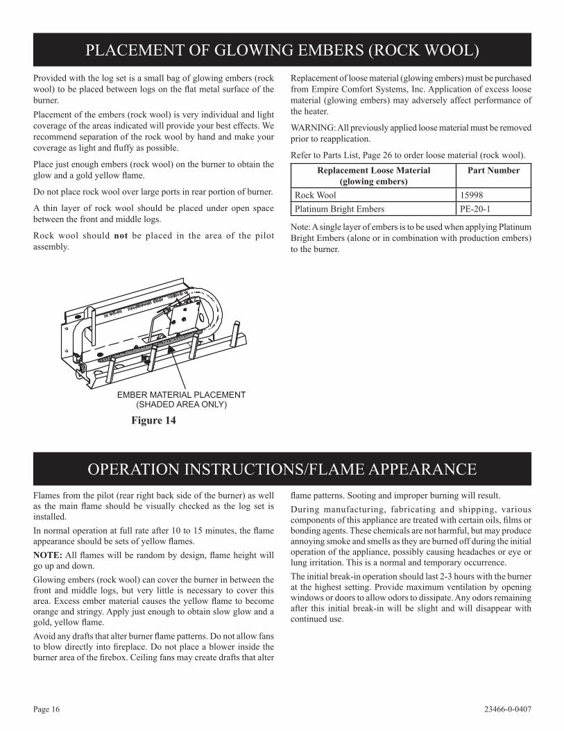
Provided with the log set is a small bag of glowing embers (rock wool) to be placed between logs on the flat metal surface of the burner.Placement of the embers (rock wool) is very individual and light coverage of the areas indicated will provide your best effects. We recommend separation of the rock wool by hand and make your coverage as light and fluffy as possible.
Place just enough embers (rock wool) on the burner to obtain the glow and a gold yellow flame.
Do not place rock wool over large ports in rear portion of burner.
A thin layer of rock wool should be placed under open space between the front and middle logs.
Rock wool should not be placed in the area of the pilot assembly.
Replacement of loose material (glowing embers) must be purchased from Empire Comfort Systems, Inc. Application of excess loose material (glowing embers) may adversely affect performance of the heater.
WARNING: All previously applied loose material must be removed prior to reapplication.
Refer to Parts List, Page 26 to order loose material (rock wool).
Note: A single layer of embers is to be used when applying Platinum Bright Embers (alone or in combination with production embers) to the burner.
Flames from the pilot (rear right back side of the burner) as well as the main flame should be visually checked as the log set is installed.In normal operation at full rate after 10 to 15 minutes, the flame appearance should be sets of yellow flames.NOTE: All flames will be random by design, flame height will go up and down.Glowing embers (rock wool) can cover the burner in between the front and middle logs, but very little is necessary to cover this area. Excess ember material causes the yellow flame to become orange and stringy. Apply just enough to obtain slow glow and a gold, yellow flame.Avoid any drafts that alter burner flame patterns. Do not allow fans to blow directly into fireplace. Do not place a blower inside the burner area of the firebox. Ceiling fans may create drafts that alter
flame patterns. Sooting and improper burning will result.During manufacturing, fabricating and shipping, various components of this appliance are treated with certain oils, films or bonding agents. These chemicals are not harmful, but may produce annoying smoke and smells as they are burned off during the initial operation of the appliance, possibly causing headaches or eye or lung irritation. This is a normal and temporary occurrence.The initial break-in operation should last 2-3 hours with the burner at the highest setting. Provide maximum ventilation by opening windows or doors to allow odors to dissipate. Any odors remaining after this initial break-in will be slight and will disappear with continued use.
PLACEMENT OF GLOWING EMBERS (ROCK WOOL)
OPERATION INSTRUCTIONS/FLAME APPEARANCE
Figure 14

Page 1723466-0-0407
WARNING: If you do not follow these instructions exactly, a fire or explosion may result causing property damage, personal injury or loss of life.
A. This appliance has a pilot which must be lighted by hand. When lighting the pilot, follow these instructions exactly.
B. BEFORE LIGHTING, smell all around the appliance area for gas. Be sure to smell next to the floor because some gas is heavier than air and will settle on the floor.
WHAT TO DO IF YOU SMELL GAS • Do not try to light any appliance • Do not touch any electrical switch; Do not use any
phone in your building • Immediately call your gas supplier from a neighbor's
phone. Follow the gas supplier's instructions.
• If you cannot reach your gas supplier, call the fire department.
C. Use only your hand to push in or turn the gas control knob. Never use tools. If the knob will not push in or turn by hand, don't try to repair it, call a qualified service tech-nician. Force or attempted repair may result in a fire or explosion.
D. Do not use this appliance if any part has been under water. Immediately call a qualified service technician to inspect the appliance and to replace any part of the control system and any gas control which has been under water.
1. Set REMOTE/OFF/ON switch to "OFF."
2. Turn off all electric power to the appliance if service is to be performed (if applicable).
3. Open bottom louver assembly (if applicable).
4. Push in gas control knob slightly and turn clockwise to "OFF". Do not force.
5. Close bottom louver assembly (if applicable).
1. STOP! Read the safety information above on this page.
2. Set REMOTE/OFF/ON switch to "OFF".
3. Turn off all electric power to the appliance (if applicable).
4. Open bottom louver assembly (if applicable).
5. Push in gas control knob slightly and turn clockwise to "OFF".
NOTE: Knob cannot be turned from "PILOT" to "OFF" unless knob is pushed in slightly. Do not force.
6. Wait ten (10) minutes to clear out any gas. Then smell for gas, including near the floor. If you smell gas, STOP! Follow "B" in the safety information above. If you do not smell gas, go to the next step.
7. Find pilot - Follow metal tube from gas control. The pilot is located next to the burner, near the right side.
8. Turn gas control knob counterclockwise to "PILOT".
9. Push in control knob all the way and hold in. Repeatedly push the Piezo Ignitor Button until the pilot is lit. Continue to hold the control knob in for about one (1) minute after the pilot is lit. Release knob, and it will pop back up. Pilot should remain lit. If it goes out, repeat steps 5 through 9.
• If knob does not pop up when released, STOP and IM-MEDIATELY call a qualified service technician or gas supplier.
• If the pilot will not stay lit after several tries, turn the gas control knob to "OFF" and call your service technician or gas supplier.
10. Turn gas control knob counterclockwise to "ON".
11. Close bottom louver assembly (if applicable).
12. Turn on all electric power to the appliance (if applicable).
13. Set REMOTE/OFF/ON switch to desired setting.
GAS CONTROL KNOBSHOWN IN "OFF" POSITION.
THERMOCOUPLE(NATURAL)
ELECTRODE
PILOTTHERMOPILE
REMOTEOFFON
THERMOCOUPLE(LPG)
GAS CONTROL KNOBSHOWN IN "OFF" POSITION.
THERMOCOUPLE(NATURAL)
ELECTRODE
PILOTTHERMOPILE
REMOTEOFFON
THERMOCOUPLE(LPG)
(A)VFD26FP3L10(N,P) LIGHTING INSTRUCTIONS
FOR YOUR SAFETY READ BEFORE LIGHTING
LIGHTING INSTRUCTIONS
TO TURN OFF GAS TO APPLIANCE

Page 18 23466-0-0407
(A)VFD26F(M,P)3 LIGHTING INSTRUCTIONS
WARNING: If you do not follow these instructions exactly, a fire or explosion may result causing property damage, personal injury or loss of life.
A. This appliance has a pilot which must be lighted by hand. When lighting the pilot, follow these instructions exactly.
B. BEFORE LIGHTING, smell all around the appliance area for gas. Be sure to smell next to the floor because some gas is heavier than air and will settle on the floor.
WHAT TO DO IF YOU SMELL GAS • Do not try to light any appliance • Do not touch any electrical switch; Do not use any
phone in your building • Immediately call your gas supplier from a neighbor's
phone. Follow the gas supplier's instructions.
• If you cannot reach your gas supplier, call the fire department.
C. Use only your hand to push in or turn the gas control knob. Never use tools. If the knob will not push in or turn by hand, don't try to repair it, call a qualified service tech-nician. Force or attempted repair may result in a fire or explosion.
D. Do not use this appliance if any part has been under water. Immediately call a qualified service technician to inspect the appliance and to replace any part of the control system and any gas control which has been under water.
1. Set REMOTE/OFF/ON switch to "OFF."
2. Turn off all electric power to the appliance if service is to be performed (if applicable).
3. Open bottom louver assembly (if applicable).
4. Push in gas control knob slightly and turn clockwise to "OFF". Do not force.
5. Close bottom louver assembly (if applicable).
1. STOP! Read the safety information above on this page.
2. Set REMOTE/OFF/ON switch to "OFF".
3. Turn off all electric power to the appliance (if applicable).
4. Open bottom louver assembly (if applicable).
5. Push in gas control knob slightly and turn clockwise to "OFF". NOTE: Knob cannot be turned from "PILOT" to "OFF" unless knob is pushed in slightly. Do not force.
6. Wait ten (10) minutes to clear out any gas. Then smell for gas, including near the floor. If you smell gas, STOP! Follow "B" in the safety information above. If you do not smell gas, go to the next step.
7. Find pilot - Follow metal tube from gas control. The pilot is located next to the burner, near the right side.
8. Turn gas control knob counterclockwise to "PILOT".
9. Push in control knob all the way and hold in. Repeatedly push the Piezo Ignitor Button until the pilot is lit. Continue to hold the control knob in for about one (1) minute after the pilot is lit. Release knob, and it will pop back up. Pilot should remain lit. If it goes out, repeat steps 5 through 9.
• If knob does not pop up when released, STOP and IM-MEDIATELY call a qualified service technician or gas supplier.
• If the pilot will not stay lit after several tries, turn the gas control knob to "OFF" and call your service technician or gas supplier.
10. Turn gas control knob counterclockwise to "ON".
11. Close bottom louver assembly (if applicable).
12. Turn on all electric power to the appliance (if applicable).
13. Set REMOTE/OFF/ON switch to desired setting.
GAS CONTROL KNOBSHOWN IN "OFF" POSITION.
THERMOCOUPLE(NATURAL)
ELECTRODE
PILOTTHERMOPILE
REMOTEOFFON
THERMOCOUPLE(LPG)
GAS CONTROL KNOBSHOWN IN "OFF" POSITION.
THERMOCOUPLE(NATURAL)
ELECTRODE
PILOTTHERMOPILE
REMOTEOFFON
THERMOCOUPLE(LPG)
GAS CONTROL KNOBSHOWN IN "OFF" POSITION.
THERMOCOUPLE(NATURAL)
ELECTRODE
PILOTTHERMOPILE
REMOTEOFFON
THERMOCOUPLE(LPG)
FOR YOUR SAFETY READ BEFORE LIGHTING
LIGHTING INSTRUCTIONS
TO TURN OFF GAS TO APPLIANCE

Page 1923466-0-0407
FOR YOUR SAFETY READ BEFORE LIGHTINGWARNING: If you do not follow these instructions exactly, a fire or explosion may result
causing property damage, personal injury or loss of life.
A. This appliance has a pilot which must be lighted by hand. When lighting the pilot, follow these instructions exactly.
B. BEFORE LIGHTING smell all around the appliance area for gas. Be sure to smell next to the floor because some gas is heavier than air and will settle on the floor.
WHAT TO DO IF YOU SMELL GAS• Do not try to light any appliance.• Do not touch any electrical switch; Do not use any phone in your building.• Immediately call your gas supplier from a neighbor's
phone. Follow the gas supplier's instructions.
• If you cannot reach your gas supplier, call the fire department.
C. Use only your hand to push in or turn the gas control knob. Never use tools. If the knob will not push in or turn by hand, don't try to repair it; call a qualified service technician. Force or attempted repair may result in a fire or explosion.
D. Do not use this appliance if any part has been under water. Immediately call a qualified service technician to inspect the appliance and to replace any part of the control system and any gas control which has been under water.
3. Push in gas control knob slightly and turn clockwise to "OFF". Do not force.
TO TURN OFF GAS TO APPLIANCE1. Set thermostat (gas control knob) to lowest setting.2. Turn off all electric power to appliance if service is to be
performed (if applicable).
LIGHTING INSTRUCTIONS 7. Turn gas control knob counterclockwise to
"PILOT." 8. Push in gas control knob all the way and hold in. Repeat-
edly push the piezo ignitor button until pilot is lit (or use a match to light pilot). Continue to hold the control knob in for about one (1) minute after the pilot is lit. Release knob and it will pop back up. Pilot should remain lit. If it goes out, repeat steps 4 through 8. • If knob does not pop up when released, stop and
immediately call your service technician or gas sup-plier.
• If the pilot will not stay lit after several tries, turn the gas control knob to "OFF" and call your service technician or gas supplier.
9. Turn gas control knob counterclockwise to "HI" (5).
10. Turn on all electric power to appliance (if applicable). 11. Set thermostat (gas control knob) to desired setting from
"HI" (5) to "LO" (1).
1. STOP! Read the safety information above. 2. Set thermostat (gas control knob) to lowest setting. 3. Turn off all electric power to the appliance (if applica-
ble). 4. Push in gas control knob slightly and turn clockwise
to "OFF". Do not force.
5. Wait ten (10) minutes to clear out any gas. Then smell for gas, including near the floor. If you smell gas, STOP! Follow "B" in the safety information above. If you don't smell gas, go to the next step.
6. Find pilot - Follow metal tube from gas control. The pilot is located next to the burner, near the right side.
(A)VFD26F(M,P)2 LIGHTING INSTRUCTIONS
PIEZO IGNITOR

Page 20 23466-0-0407
Figures 15 and 18 show a correct pilot flame pattern. The correct flame will be blue and will extend beyond the thermocouple. The flame will surround the thermocouple just below the tip. A slight yellow flame may occur where the pilot flame and main burner flame meet. Figures 16 and 19 show an incorrect pilot flame pattern. The incorrect pilot flame is not touching the thermocouple. This will cause the thermocouple to cool. When the thermocouple cools, the heater will shut down.
(A)VFD26F(M,P)3 PILOT
Correct Pilot Flame Pattern
Figure 15
Incorrect Pilot Flame Pattern
Figure 16
If pilot flame pattern is incorrect, as shown in Figure 15• See Troubleshooting, page 25.
Cleaning and Maintenance/PilotOxygen Depletion Sensor PilotWhen the pilot has a large yellow tip flame, clean the Oxygen Depletion Sensor as follows:
1. Clean the ODS pilot by loosening nut B from the pilot tubing. When this procedure is required, grasp nut A with an open end wrench.
2. Blow air pressure through the holes indicated by the arrows.
This will blow out foreign materials such as dust, lint and spider webs. Tighten nut B also by grasping nut A.
Warning: Never use needles, wires, or similar cylindrical objects to clean the pilot to avoid damaging the calibrated ruby that controls the gas flow.
Figure 17
(A)VFD26F(M,P)2 PILOT
Correct Pilot Flame PatternFigure 18
Incorrect Pilot Flame PatternFigure 19
If pilot flame pattern is incorrect, as shown in Figure 19• See Troubleshooting, page 25.
PILOT FLAME CHARACTERISTICS

Page 2123466-0-0407
Cleaning and Maintenance/PilotOxygen Depletion Sensor PilotWhen the pilot has a large yellow tip flame, clean the Oxygen Depletion Sensor as follows:
1. Clean the ODS pilot by loosening nut B from the pilot tubing. When this procedure is required, grasp nut A with an open end wrench.
2. Blow air pressure through the holes indicated by the arrows. This will blow out foreign materials such as dust, lint and spider webs. Tighten nut B also by grasping nut A.
Warning: Never use needles, wires, or similar cylindrical objects to clean the pilot to avoid damaging the calibrated ruby that controls the gas flow.
The (A)VFD26F(M,P)3 gas control maximum and minimum inputs are listed below.OFF is the OFF position.PILOT is the PILOT position.(A)VFD26F(M,P)3Max. 20,000 BTU/HRMin. 14,000 BTU/HR
(A)VFD26FP3L10Max. 10,000Min. N/A(A)VFD26F(M,P)2 Main Burner OperationThe gas control modulates from a minimum input of 14,000 BTU/HR ("LO" (1) setting) to a maximum input of 20,000 BTU/HR ("HI" (5) setting).
Figure 20
Cleaning and Maintenance / Main BurnerWarning: Turn off heater and let cool before cleaning.Caution: You must keep control areas, burner and circulating air passageways of heater clean. Inspect these areas of heater before each use. Have heater inspected yearly by a qualified service person. Heater may need more frequent cleaning due to excessive lint from carpeting, bedding materials, etc. LogsBe careful cleaning and handling logs so as not to damage them. If logs break or fall apart in handling, spray the broken pieces and fibers with water, sweep up and discard.
MAIN BURNER AND THERMOSTAT OPERATION
Page 22 23466-0-0407
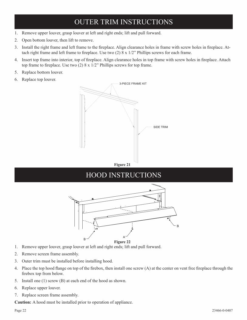
OUTER TRIM INSTRUCTIONS1. Remove upper louver, grasp louver at left and right ends; lift and pull forward.2. Open bottom louver, then lift to remove.3. Install the right frame and left frame to the fireplace. Align clearance holes in frame with screw holes in fireplace. At-
tach right frame and left frame to fireplace. Use two (2) 8 x 1/2” Phillips screws for each frame.4. Insert top frame into interior, top of fireplace. Align clearance holes in top frame with screw holes in fireplace. Attach
top frame to fireplace. Use two (2) 8 x 1/2” Phillips screws for top frame.5. Replace bottom louver.6. Replace top louver.
3-PIECE FRAME KIT
SIDE TRIM
Figure 21
HOOD INSTRUCTIONS
1. Remove upper louver, grasp louver at left and right ends; lift and pull forward.2. Remove screen frame assembly.3. Outer trim must be installed before installing hood.4. Place the top hood flange on top of the firebox, then install one screw (A) at the center on vent free fireplace through the
firebox top from below.5. Install one (1) screw (B) at each end of the hood as shown.6. Replace upper louver.7. Replace screen frame assembly.Caution: A hood must be installed prior to operation of appliance.
Figure 22

Page 2323466-0-0407
Label all wires prior to disconnection when servicing controls. Wiring errors can cause improper and dangerous operation. Verify proper operation after servicing.
Millivolt thermopile is self powered, gas valve does not require 110 volts. Maximum length of 20 feet of 16 AWG to conductor wires is to be used with all optional components.
Use the two leads (Green and Red wires) to attach optional components.
Check 750 Millivolt System OperationMillivolt system and all individual components may be checked with a millivolt meter 0-1000 MV range.
Remote ReceiverUse the following steps to place the remote receiver adjacent to the gas valve.
Attention: The remote receiver bracket is not used in this installation.
1. The remote receiver can not be placed behind the gas valve and burner assembly.
2. When facing the appliance, the remote receiver must be placed to the right of the gas valve and burner assembly.
Note: Do not let remote control receiver come in contact with burner assembly.On circulating vent-free firebox, install remote control receiver behind bottom louver.Refer to remote control installation and operating instructions for more details on remote control.
(A)VFD26F3 WIRING
REMOTE/OFF/ON SWITCHA DISTANCE/FERME/OUVERTINTERRUPTEUR
IF ANY OF THE ORIGINAL WIREAS SUPPLIED WITH THIS UNITMUST BE REPLACED, IT MUST BEREPLACED WITH NUMBER 18, 150°CWIRE OR ITS EQUIVALENT.
SI UN DES FILS ELECTRIQUESORIGINAUX, VENANT DU FABRICANTAVEC CETTE UNITE, DOIT ETREREMPLACE, VOUS DEVEZ LEREMPLACER AVEC UN FILELECTRIQUE DE NUMERO 18,150 ° C DU L'EQUIVALENT.
THERMOPILE
GAS VALVE
THERMOCOUPLE(NATURAL)
OFFON
REMOTE
(OPTIONAL) REMOTE CONTROL RECEIVER(FACULTATIVE) CONTROLE E DISTANCEDU RECEPTEUR
(OPTIONAL) WALL SWITCHINTERRUPTEUR MURAL(FACULTATIVE)
(OPTIONAL) THERMOSTAT(FACULATIVE) THERMOSTAT
WIRING DIAGRAM
GAS VALVEVALVE DE GAZ
REMOTE/OFF/ON SWITCHA DISTANCE/OUVERT/FERME INTERRUPTEUR
REMOTE CONTROL RECEIVER/THERMOSTAT/ CONTROLE EDISTANCE DU RECEPTEUR
H N
VEILLEUSEPILOT
THERMOCOUPLE(LPG)
Figure 23
Page 24 23466-0-0407
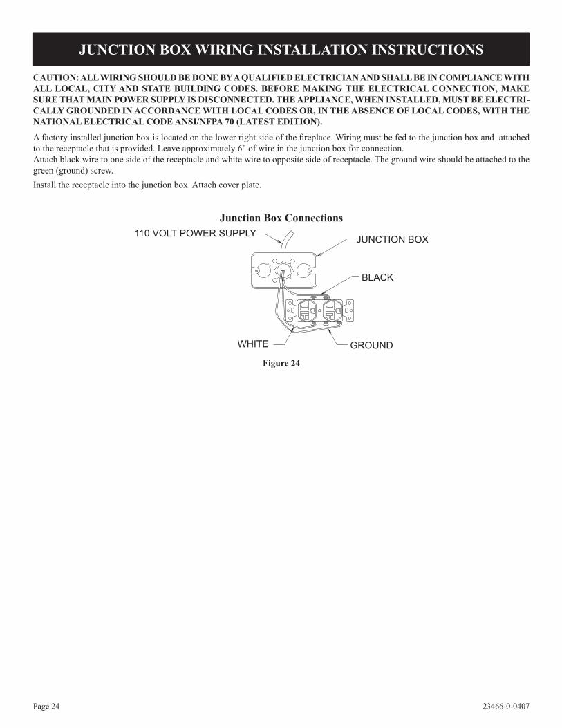
CAUTION: ALL WIRING SHOULD BE DONE BY A QUALIFIED ELECTRICIAN AND SHALL BE IN COMPLIANCE WITH ALL LOCAL, CITY AND STATE BUILDING CODES. BEFORE MAKING THE ELECTRICAL CONNECTION, MAKE SURE THAT MAIN POWER SUPPLY IS DISCONNECTED. THE APPLIANCE, WHEN INSTALLED, MUST BE ELECTRI-CALLY GROUNDED IN ACCORDANCE WITH LOCAL CODES OR, IN THE ABSENCE OF LOCAL CODES, WITH THE NATIONAL ELECTRICAL CODE ANSI/NFPA 70 (LATEST EDITION).
A factory installed junction box is located on the lower right side of the fireplace. Wiring must be fed to the junction box and attached to the receptacle that is provided. Leave approximately 6" of wire in the junction box for connection.Attach black wire to one side of the receptacle and white wire to opposite side of receptacle. The ground wire should be attached to the green (ground) screw.Install the receptacle into the junction box. Attach cover plate.
JUNCTION BOX WIRING INSTALLATION INSTRUCTIONS
Figure 24
Junction Box Connections
Page 2523466-0-0407
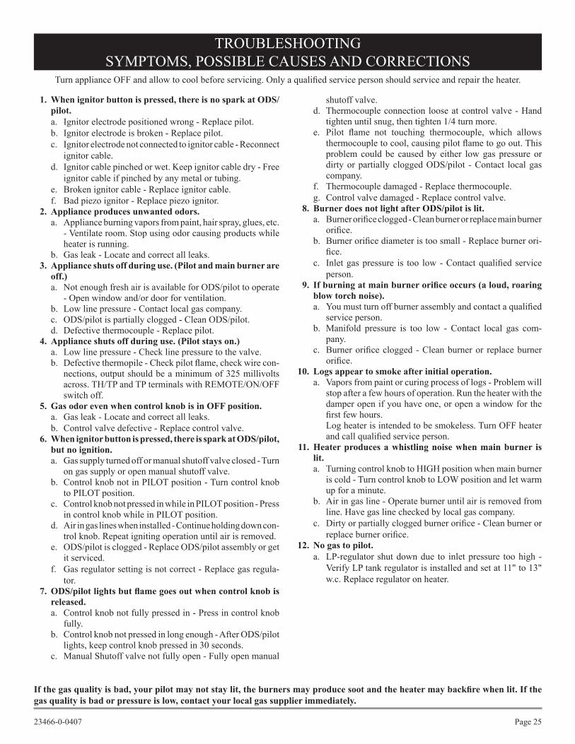
If the gas quality is bad, your pilot may not stay lit, the burners may produce soot and the heater may backfire when lit. If the gas quality is bad or pressure is low, contact your local gas supplier immediately.
1. When ignitor button is pressed, there is no spark at ODS/pilot. a. Ignitor electrode positioned wrong - Replace pilot.b. Ignitor electrode is broken - Replace pilot.c. Ignitor electrode not connected to ignitor cable - Reconnect
ignitor cable.d. Ignitor cable pinched or wet. Keep ignitor cable dry - Free
ignitor cable if pinched by any metal or tubing. e. Broken ignitor cable - Replace ignitor cable.f. Bad piezo ignitor - Replace piezo ignitor.
2. Appliance produces unwanted odors.a. Appliance burning vapors from paint, hair spray, glues, etc.
- Ventilate room. Stop using odor causing products while heater is running.
b. Gas leak - Locate and correct all leaks. 3. Appliance shuts off during use. (Pilot and main burner are
off.)a. Not enough fresh air is available for ODS/pilot to operate
- Open window and/or door for ventilation.b. Low line pressure - Contact local gas company.c. ODS/pilot is partially clogged - Clean ODS/pilot.d. Defective thermocouple - Replace pilot.
4. Appliance shuts off during use. (Pilot stays on.)a. Low line pressure - Check line pressure to the valve.b. Defective thermopile - Check pilot flame, check wire con-
nections, output should be a minimum of 325 millivolts across. TH/TP and TP terminals with REMOTE/ON/OFF switch off.
5. Gas odor even when control knob is in OFF position.a. Gas leak - Locate and correct all leaks.b. Control valve defective - Replace control valve.
6. When ignitor button is pressed, there is spark at ODS/pilot, but no ignition.a. Gas supply turned off or manual shutoff valve closed - Turn
on gas supply or open manual shutoff valve.b. Control knob not in PILOT position - Turn control knob
to PILOT position.c. Control knob not pressed in while in PILOT position - Press
in control knob while in PILOT position.d. Air in gas lines when installed - Continue holding down con-
trol knob. Repeat igniting operation until air is removed.e. ODS/pilot is clogged - Replace ODS/pilot assembly or get
it serviced.f. Gas regulator setting is not correct - Replace gas regula-
tor. 7. ODS/pilot lights but flame goes out when control knob is
released.a. Control knob not fully pressed in - Press in control knob
fully.b. Control knob not pressed in long enough - After ODS/pilot
lights, keep control knob pressed in 30 seconds.c. Manual Shutoff valve not fully open - Fully open manual
shutoff valve.d. Thermocouple connection loose at control valve - Hand
tighten until snug, then tighten 1/4 turn more.e. Pilot flame not touching thermocouple, which allows
thermocouple to cool, causing pilot flame to go out. This problem could be caused by either low gas pressure or dirty or partially clogged ODS/pilot - Contact local gas company.
f. Thermocouple damaged - Replace thermocouple.g. Control valve damaged - Replace control valve.
8. Burner does not light after ODS/pilot is lit.a. Burner orifice clogged - Clean burner or replace main burner
orifice.b. Burner orifice diameter is too small - Replace burner ori-
fice.c. Inlet gas pressure is too low - Contact qualified service
person. 9. If burning at main burner orifice occurs (a loud, roaring
blow torch noise).a. You must turn off burner assembly and contact a qualified
service person.b. Manifold pressure is too low - Contact local gas com-
pany.c. Burner orifice clogged - Clean burner or replace burner
orifice. 10. Logs appear to smoke after initial operation.
a. Vapors from paint or curing process of logs - Problem will stop after a few hours of operation. Run the heater with the damper open if you have one, or open a window for the first few hours.
Log heater is intended to be smokeless. Turn OFF heater and call qualified service person.
11. Heater produces a whistling noise when main burner is lit.a. Turning control knob to HIGH position when main burner
is cold - Turn control knob to LOW position and let warm up for a minute.
b. Air in gas line - Operate burner until air is removed from line. Have gas line checked by local gas company.
c. Dirty or partially clogged burner orifice - Clean burner or replace burner orifice.
12. No gas to pilot.a. LP-regulator shut down due to inlet pressure too high -
Verify LP tank regulator is installed and set at 11" to 13" w.c. Replace regulator on heater.
Turn appliance OFF and allow to cool before servicing. Only a qualified service person should service and repair the heater.
TROUBLESHOOTINGSYMPTOMS, POSSIBLE CAUSES AND CORRECTIONS

Page 26 23466-0-0407 Empire Comfort Systems, Inc. Nine Eighteen Freeburg Ave. Belleville, Illinois 62220-2623
ATTENTION: When ordering parts, it is very important that part number and description of part coincide.
PARTS LIST
INDEX PARTNUMBER NUMBER DESCRIPTION
COMMON PART NUMBERS1 10554 NAILING FLANGE2 17162 JUNCTION BOX ASSEMBLY3 23461 TRIM - TOP4 23462 TRIM – LEFT5 23463 TRIM – RIGHT6 23464 LOUVER ASSEMBLY – UPPER7 23465 LOUVER ASSEMBLY – LOWER8 23460 HOOD9 23470 SCREEN FRAME ASSEMBLY13 17235 BRACKET, LOG LOCATOR15 R7624 AIR SHUTTER17 R7572 JAMB NUT18 P212 FITTING, ORIFICE20 R2423 CONNECTOR, MALE22 23473 BURNER BASE PLATE ASSEMBLY26 23450 VALVE BRACKET29 R2708 IGNITOR, PIEZO31 R7587 REAR LOG32 R7586 MIDDLE LOG33 R7585 FRONT LEFT LOG34 R7554 FRONT RIGHT LOG35 R7588 Y-TWIGN/S R5668 IGNITOR WIREN/S 15998 ROCK WOOL
(A)VFD26F(M,P)3LN PART NUMBERS10 R3624 PILOT ASSEMBLY11 23106 PILOT BRACKET12 23449 PILOT SHIELD14 R9022 BURNER TUBE16 P288 ORIFICE19 23493 TUBING ASSEMBLY21 R3626 VALVE23 23492 TUBING ASSEMBLY24 R7063 REGULATOR, NAT PILOT25 23491 TUBING ASSEMBLY30 R3436 SWITCH, REMOTE/OFF/ONN/S R3435 WIRE ASSEMBLY
(A)VFD26F(M,P)3LP PART NUMBERS10 R3623 PILOT ASSEMBLY11 21590 PILOT BRACKET14 R9022 BURNER TUBE16 P182 ORIFICE19 23493 TUBING ASSEMBLY21 R3625 VALVE23 23496 TUBING ASSEMBLY30 R3436 SWITCH, REMOTE/OFF/ONN/S R3435 WIRE ASSEMBLY
INDEX PARTNUMBER NUMBER DESCRIPTION
(A)VFD26F(M,P)2LN PART NUMBERS10 R5171 PILOT ASSEMBLY11 23106 PILOT BRACKET12 23449 PILOT SHIELD14 R9022 BURNER TUBE16 P265 ORIFICE19 23475 TUBING ASSEMBLY21 23477 VALVE23 23476 TUBING ASSEMBLY27 P239 NIPPLE, 3/8 NPT X 1 ½28 R2479 REGULATOR
(A)VFD26F(M,P)2LP PART NUMBERS10 R5170 PILOT ASSEMBLY11 21590 PILOT BRACKET14 R9022 BURNER TUBE16 P182 ORIFICE19 23475 TUBING ASSEMBLY21 23478 VALVE23 23476 TUBING ASSEMBLY27 P239 NIPPLE, 3/8 NPT X 1 ½28 R2480 REGULATOR
(A)VFD26FP3L10N PART NUMBERS10 R3624 PILOT ASSEMBLY11 23106 PILOT BRACKET12 23449 PILOT SHIELD14 R9276 BURNER TUBE16 P214 ORIFICE19 23493 TUBING ASSEMBLY21 R9368 VALVE23 23492 TUBING ASSEMBLY24 R7063 REGULATOR, NAT PILOT25 23491 TUBING ASSEMBLY30 R3436 SWITCH, REMOTE/OFF/ONN/S R3435 WIRE ASSEMBLY
(A)VFD26FP3L10P PART NUMBERS10 R3623 PILOT ASSEMBLY11 21590 PILOT BRACKET14 R9276 BURNER TUBE16 P193 ORIFICE19 23493 TUBING ASSEMBLY21 R9369 VALVE23 23496 TUBING ASSEMBLY30 R3436 SWITCH, REMOTE/OFF/ONN/S R3435 WIRE ASSEMBLY

Page 2723466-0-0407
PARTS VIEW
5 PIECE LOG YASSEMBLMILLIVOLT VALVE
YASSEMBLTHERMOSTATIC VALVE
YASSEMBL
1
2
3
4
5
6
7
8
9
10
1112
13
14
151617
18
19
19
20
2021
21
22
23
23
24
25
26
27 28
29
29
30
31
1832
33
34
35
26
1
1
1

Page 28 23466-0-0407
For Unvented Gas Fireplace Model (A)VFD26F(M,P)2, (A)VFD26F(M,P)3
FBBX BLOWER KIT EXTENSION INSTALLATION INSTRUCTIONS
Disregard FBB4 Blower Installation Instructions. Follow the in-stallation instructions with your FBBX blower extension kit or the (A)VFD26 Instruction Manual.
Attention: If installed, do not damage gas inlet supply line when blower assembly is inserted into fireplace. Removal of the gas inlet supply line will be necessary.
1. Remove blower parts from the FBB4 kit and the parts from the FBBX kit.
2. Remove fan control from wire harness in the FBB4 kit.3. Attach the fan control to the fan control bracket using the 2-
8x1/4” screws provided.4. If installed, turn OFF gas supply to fireplace.5. If applicable, turn OFF electric supply to fireplace.6. Lower bottom louver on fireplace.7. Remove upper louver.8. Remove screen frame assembly9. If applicable, remove logs from burner assembly.10. Remove burner assembly from firebox (3 screws).
See Figure 26.11. Position blower assembly behind gas valve, align notch on
back of blower assembly with center screw on fireplace back and push blower assembly against fireplace back. The bower wheel must be centered with the back wall of the fireplace. Place blower assembly against the back wall. The magnets on the back and bottom of blower assembly will sufficiently hold blower assembly in place.
12. Position speed control to the right of gas valve. Attach speed control to bottom of fireplace. The magnets on the bottom of speed control will sufficiently hold the speed control in place.
13. Attach fan control bracket to upper right side of firebox with one #10 x 1/2 hex screw provided. See Figure 25.
14. Attach wire harness from the FBBX kit to the terminals on the fan control.
15. Route the wire harness along the right side of the firebox.16. Connect the wire harness from the fan control to the wire har-
ness from the speed control.17. Insert power cord plug into junction box.18. Replace burner assembly in firebox with the three (3) screws
removed in Step 10.19. If applicable, replace logs onto burner assembly.20. Replace screen frame assembly.21. Install upper louver. Close bottom louver on fireplace.Note: This blower is equipped with a heat activated fan control
switch. Fan will operate when the fireplace warms up, and will turn off when the fireplace cools down.
22. Installation of FBB4 and FBBX option variable speed blower assembly is completed.
Blower MotorThe blower motor does not have oiling holes. Do not attempt to oil the blower motor.
Blower WheelsThe blower wheels will collect lint and could require periodic cleaning. If the air output decreases or the noise level increases, it indicates a dirty blower wheel. Remove fan and clean blower wheels.
Warning: Unplugging of blower accessory will not stop the heater from cycling. To turn off gas to the heater (millivolt model): push in gas control knob slightly and turn clockwise to OFF.” Do not force.
FAN SWITCH
FAN KITSPEED CONTROL
JUNCTION BOX
SWITCHBRACKET
FAN CONTROLBRACKETSCREW HOLE
BRICK LINERRETAINERSCREW HOLE
Figure 25
REMOVEREMOVE
REMOVE
Figure 26

Page 2923466-0-0407
1 11508 SWITCH BRACKET
2 R-9377 HARNESS
N/S R-1131 SCREWS
N/S R-2737 #10 X 1/2 SCREWS
1 2
FBBX Blower Kit
110 VOLT ACJUNCTION BOX
WHITE
SPEEDCONTROL
FANSWITCH
GROUND
BLACK
FAN
WHITE
BLACK
SWITCHBRACKET
FBBX Wiring Diagram
FBBX BLOWER KIT EXTENSION INSTALLATION INSTRUCTIONS (cont.)
FBB4 OPTIONAL VARIABLE SPEED BLOWER
1 FBB4 BLOWER ASSEMBLY COMPLETE
2 R7649 FAN CONTROL3 R4192 SPEED CONTROL KNOB4 R4186 SPEED CONTROL

Page 30 23466-0-0407
FPP26E OPTIONAL BRICK LINER KIT INSTALLATION INSTRUCTIONS
1. Remove screen from fireplace.2. Remove branch log and rear log from burner assembly.3. Insert back panel into firebox.4. Insert one (1) side panel into firebox.5. Align clearance hole on brick panel bracket with screw hole in the left or right interior top of firebox. Use two (2) 10 x 1/2" screws
to attach brick panel bracket to interior, top of firebox.6. Repeat steps 4 and 5 to install second side panel.7. Replace rear log and branch log onto burner assembly.8. Replace screen onto fireplace.9. Installation of optional brick liner is complete.
Page 3123466-0-0407
Parts can be ordered only through your service person or dealer. For best results, the service person or dealer should order parts through the distributor. Parts can be shipped directly to the service person/dealer.All parts listed in the Parts List have a Part Number. When ordering parts, first obtain the Model Number from the name plate on your equipment. Then determine the Part Number (not the Index Number) and the Description of each part from the following appropriate illustration and list. Be sure to give all this information.
Fireplace Number Part Description
Fireplace Serial Number Part Number
Type of Gas (Propane or Natural)
Do not order bolts, screws, washers or nuts. They are standard hardware items and can be purchased at any local hardware store. Shipments contingent upon strikes, fires and all causes beyond our control.
Empire Comfort Systems, Inc. Nine Eighteen Freeburg Ave. Belleville, Illinois 62222-2623
SERVICE NOTES
HOW TO ORDER REPAIR PARTS

Page 32 23466-0-0407
Empire Comfort Systems, Inc.918 Freeburg Ave. Belleville, IL 62222PH: 618-233-7420 or 800-851-3153FAX: 618-233-7097 or [email protected]
www.empirecomfort.com