installation, care and operation of circuit breakers …...installation, care and operation of...
TRANSCRIPT
� Installation, Care and Operation
of Circuit Breakers and Accessories
TYPE LA-l5A and LA-25! MANUAL STORED-ENEBGY
AIR CIRCUIT · BREAKER
, BOOK BWX-6 559-l
These instructions are not intended to cover all details or variations that may be encountered in connection with the installation, operation, and maintenance of this equipment. Should additional information be desired contact the Allis-Chalmers Mfg. Company.
AIIIS·(HAIMERS MF6.(0. BOSTON WORKS • BOSTON • MASS. www . El
ectric
alPar
tMan
uals
. com

www . El
ectric
alPar
tMan
uals
. com
,t_.:::_';:,
ALLIS-CHALMERS � MANUFACTURING COMPANY
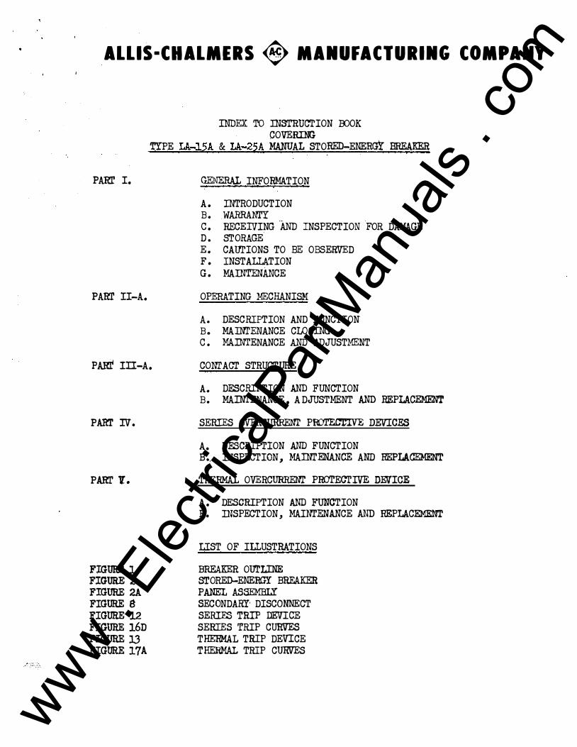
INDEX TO INSTRUCTION :OOOK COVERING
TYPE LA-.l5A & LA-25A MANUAL STORED-ENERGY BREAKER
PARr I. GENERAL INFORMATION
A. INTRODUCTION B. WARRANl'Y c. RECEIVING AND INSPECTION FOR DAMAGE D. STORAGE E. CAUTIONS TO BE OBSERVED F. INSTALLATION G. MAINTENANCE
PAm' II-A. OPERATING MECHANISM
A . DESCRIPTION AND FUNCTION B. MAOO'ENANCE CLOSING c. MAJNI'ENANCE AND ADJUSTMENT
PARf In-A. CONI' ACT STRUCTURE
A. DESCRIPTION AND FUNCTION B. MAINTENANCE, A DJUSTMENT AND REPLACEMENT
PARr IV. SERIES OVERCURRENT POOTEC'ro:VE DEVICES
A. DESCRIPTION AND FUNCTION B •. INSPECTION, MAINrENANCE AND REPLACEMENT
PARI' V. THERMAL OVERCURR.Em' PROTECTIVE DEVICE
A. DESCRIPTION AND FUNCTION B. INSPECTION, MAINI'ENANCE AND REPLACEMENT
LIST OF ILLUSTRATIONS
FIGURE 1 BREAKER OUTLINE FIGURE 2 STORED-ENERGY BREAKER FIGURE 2A PANEL ASSEMBLY FIGURE g SECONDARY' DISCONNECT FIGURE 12 SERIES TRIP DEVICE
FIGURE 16D SERIES TRIP CURVES FIGURE l3 THERMAL TRIP DEVICE FIGURE 17A THERMAL TRIP CURVES
www . El
ectric
alPar
tMan
uals
. com

www . El
ectric
alPar
tMan
uals
. com
Instructions For the Installation and Operation
of Allis-Chalmers Type 11LA"
Low Voltage Air Circuit Breakers and Auxiliary Eq:D-pment
Part I GENERAL INFORMATION
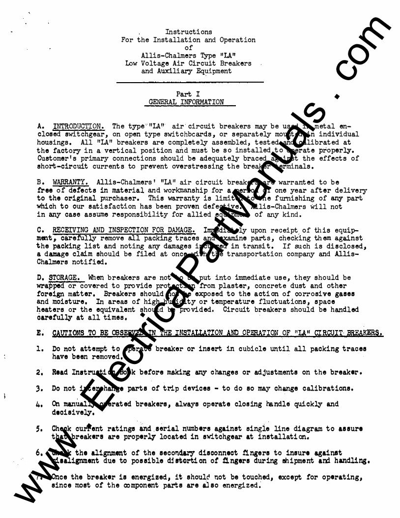
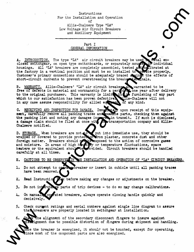
A. INTRODUCTION. The type··nLAn air circuit breakers may be used in metal enclosed switchgear, on open type switchbcards, or separately mounted in individual housings. All 11LA" breakers are completely assembled, tested and calibrated at the factory in a vertical position and must be so installed to operate properly. Customer's primary connections should be adequately braced against the effects of short-circuit currents to prevent overstressing the breaker terminals.
B. WARRANTY . Allis-Chalmers 1 11LA11 air circuit breakers are warranted to be free of defects in material and workmanship for a period of one year after delivery to the original purchaser. This warranty is limited to the furnishing of any part which to our satisfaction has been proven defective. Allis-Chalmers will not in any case assume responsibility for allied equipment of any kind.
C. RECEIVING AND INSPECTION FOR DAMAGE. Immediately upon receipt of this equipment,. carefully remove all packing traces and examine parts, checking them against the pack ing list and noting any damages incurred in transi t. If such is disclosed, a damage claim should be filed at once with the transportation company and AllisChalmers notified.
D, STORAGE. When breakers are not to be put into immediate use, they should be wrapped or covered to provide protection from plaster, concrete dust and other foreign mat ter , Breakers should not be exposed to the action of corrosive gases and moisture, In areas of high humidity or temper ature fluctuations, space heaters or the equivalent should be provided, Circuit breakers should be handled oarefullf at all times,
�� CAUTIONS TO BE OBSERVED IN THE INSTALLATION AND OPERATION OF 11LA11 CIRCUIT BREAKERS. l. Do not attempt to operate breaker or insert in cubicle until all packing traces
have been removed,
2, Read Inatruotion Book before making any changes or adjustments on the breaker.
) . Do not interchange parte of trip devices - to do eo may change calibrations. '
4. On manually operated breakers, always operate closing handle quick:cy and dtoieivezy,
;. Cheok current ratings and serial numbers against single line diagram to assure that breakers are properlf located in switchgear at installation.
6. Cheok the alignment of the eeconclaey disconne ct !ingere to insure against miealignment d ue to pos eible d� atcrti on ot fingers during shipme nt ani ha.nd.lin&•
7. Once the breaker ie energized., it shoul,c:4 not be touched, except for operating, since most of the component parts are aJeo energized, www .
Elec
tricalP
artM
anua
ls . c
om
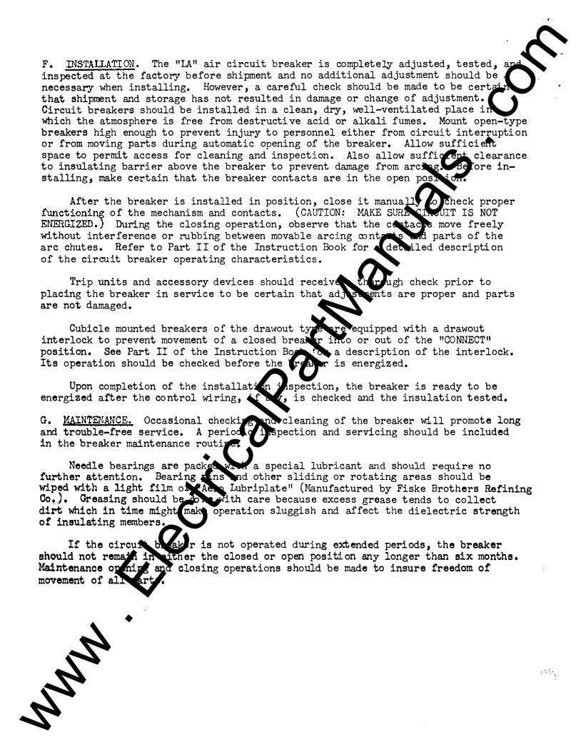
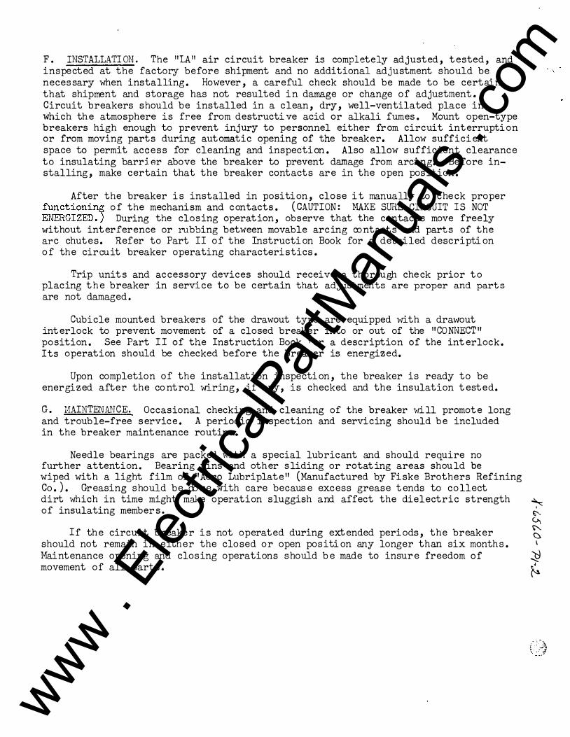
F. INSTALLATION. The 11LA11 air circuit breaker is completely adjusted, tested, and inspected at the factory before shipment and no additional adjustment should be , necessary when installing. However, a careful check should be made to be certain that shipment and storage has not resulted in damage or change of adjustment. Circuit breakers should be installed in a clean, dry, well-ventilated place in Which the atmosphere is free from destructi ve acid or alkali fumes. Mount open-type breakers high enough to prevent injury to personnel either from circuit interruption or from moving parts during automatic opening of the breaker. Allow sufficient space to permit access for cleaning and inspection. Also allow sufficient clearance to insulating barrier above the breaker to prevent damage from arcing. Before installing, make certain that the breaker contacts are in the open position.
After the breaker is installed in position, close it manually to check proper fu.nctioni� o f the mechanism and contacts. (CAUTION: MAKE SURE CIRCUIT IS NOT ENERGIZED.) During the closing operation, observe that the contacts move freely without interference or rubbing between movable arcing oontacts and parts of the arc chutes. Refer to Part II of the Instruction Book for a detailed descripti on of the circuit breaker operating characteristics.
Trip units and accessory devices should receive a thorough check prior to placing the breaker in service to be certain that adjustments are proper and parts are not damaged.
Cubicle mounted breakers of the dra\.,.out type are equipped with a drawout interlock to prevent movement of a closed breaker into or out of the 11CONNECT11 position . See Part II of the Instruction Book �or a description of the interlock. Its operation should be checked before the breaker is energized.
Upon completion of the installation inspection, the breaker is ready to be energized after the co ntrol wiring, if any, is checked and the insulation tested.
G. MAINTENANCE. Occasional checking and cleaning of the breaker will promote long a nd trouble-free service. A periodic inspection and servicing should be included in the breaker maintenance routine.
Needle bearings are packed with a special lubricant and should require no further attention. Bearing pins and other sliding or rotating areas should be wiped with a light film of "Aero Lubriplate" (Manufactured by Fiske Brothers Refining Co.). �easing should be done with care because excess grease tends to collect dirt which in time might make operation sluggish and affect the dielectric strength of insulating members .
If the circuit breaker is not operated during extend�d peri ods, the breaker should not remain in either the close d or open position any longer than six months. Maintenance opening and closing operations should be made to insure freedom of movement of all parts.
www . El
ectric
alPar
tMan
uals
. com

PARI.' ll--A
OPERATING MECHANISM
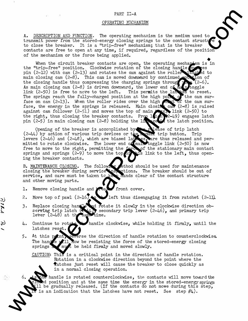
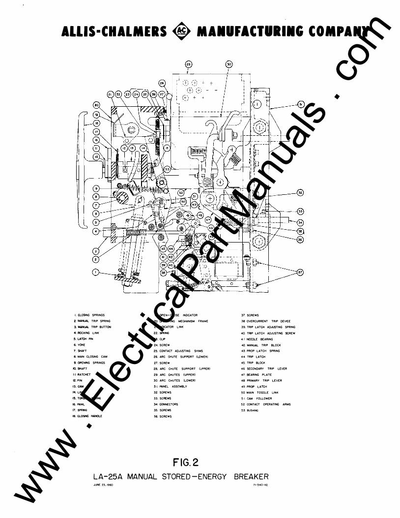
A. DESCRIPTION AND FUNCTION. The operating mechanism is t.he medium used to transmit power from the s'Oored-energy- closing springs to the eontact structure to close the breaker. It is a "trip--tree" meohanismJ that is, the breaker contacts are free to open at a:rry time, if requinld._, regardless of the position of the mechanism or the force being a.ppli$d.
When the circuit breaker contacts are open, the operating mechanism is in the'�rip-free" position. Clockwise rotation of the closing handle engages pin (2-12) with cam (2-13) and rotates the ea.m against the roller attached to main closing cam (2-8), This eam is moved do"WJ);Wa.l"d by csontinued rotation of the closing handle thus compressing the aharging $prings through yoke (2-6). As main closin� cam (2-8) is driven downward, the lower end of main toggle link (2-50) is free to move to the left. This permits the latdhes to reset. The springs reach the fUlly-charged position at the high point of the cam surface on cam (2-1.3). When the roller rides over the high point of the cam surface, the energy in the springs is released. Main closing cam (2-8) is raised against cam follower {..2-51) and moves the top of main toggle link (2-50) to the right, thus closing the breaker contacts. Prop latch (2-49) engages latch pin (2-5) in main closing cam (2-8) holding the linkage in the latch position. J
Opening of the breaker is accomplished by the release of trip la.tcit (2-44) by action of various trip devices or the manual trip button. Trip levers (2-46) and (2-48), Which are biased latches, are thus released and permitted to rotate clockwise. The lower end of main toggle link (2-50) is now free to move to the right, permitting the force of t he stationary main contact springs and springs (2-9) to move the top of this· link to the left, thus opening the breaker contacts.
B. MAINTENANCE ClOSING. The following method should be used for maintenance closing the breaker during service inspections. The breaker should be out of service, and care must be taken to keep hands clear of the contact structure and other moving parts.
1. Remove closing handle and breaker front cover. 2. MOve t�p of pawl (2-16) to the left as far as it will go •
.3. Replace closing handle and rotate it slowly in the clockwise direction observing trip latch (2-44), secondary trip lever (2-46), and pri�r,r trip lever (2-48) at the same time.
4. Continue to rotate the handle clockwise, while holding it firmly� until the latches reset. Just beyond this point� the stop in the ratchet will engage the lower end of the pawl and prevent further clockwise rotation.
5. Reverse t he direction of handle rotation to counterclockwise. The handle will now be resisting the force of the stored-energy closing springs and must be held firmly.
6. As the handle is rotated ceunterolockwise, the contacts will move toward the closed position and at the same time the energy in the stored-energy springs will be gradually released. (If the contacts do not move during this step, it is an indication that the latches have not reset. See Step #4) .. www .
Elec
tricalP
artM
anua
ls . c
om
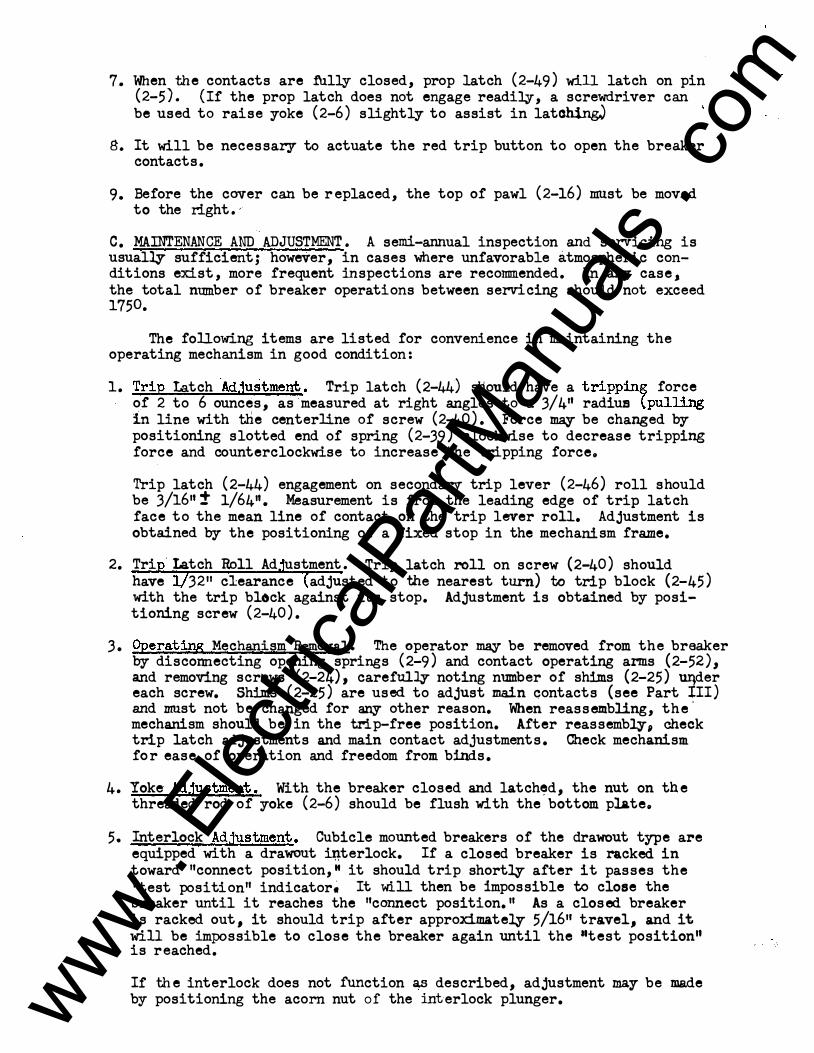
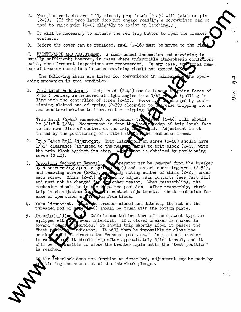
7. When the contacts are fully closed, prop latch (2-49) will latch on pin (2-5). (If the prop latch does not engage readily, a screwdriver can be used to raise yoke (2-6) slightly to assist in late�
B. It will be necessary to actuate the red trip button to open the breaker contacts.
9. Before the cover can be replaced, the top of pawl (2-16) must be moved to the right.,
C. MAINTENANCE AND ADJUSTMENT. A semi-armual inspection and servicing is usually sufficient; however, in cases where unfavorable atmospheric conditions exist, more frequent inspections are recommended. In any case, the total number of breaker operations between servicing should not exceed 1750.
The following items are listed for convenience in maintaining the operating mechanism in good condition:
1. Trip ta.tch ·Adjustment. Trip latch (2-44) stiould have a trippin� force of 2 to 6 ounces, as measured at right angles to a 3/411 radius tpulling in line with the centerline of screw (2-40). Force may be changed by positioning slotted end of spring (2-39) clockwise to decrease tripping force and counterclockwise to increase the tripping forceo
Trip latch (2-44) engagement on secondar,r trip lever (2-46) roll should be 3/1611 t 1/6411• Measurement is from the leading edge of trip latch face to the mean line of contact on the trip lever roll. Adjustment is obtained by the positioning of a fixed stop in the mechanism frame.
2. Tri ·Latch Roll Ad ustment. Trip latch roll on screw (2-40) should have 3211 clearance adjusted to the nearest turn) to trip block (2-45) with the trip block against its stop. Adjustment is obtained by positioning screw (2-40).
3. Operating Mechanism Removal. The operator may be removed from the breaker by disconnecting opening springs (2-9) and contact operating arms (2-52), and removing screws (2-24), carefully noting ntnnber of shims (2-25) uqder each screw. Shims (2-25) are used to adjust main contacts (see Part III) and must not be changed for any other reason. When reassembling, the' mechanism should be in the trip-free position. After reassembly, cheek trip latch adjustments and main contact adjustments. Check mechanism for ease of operation and freedom from binds.
4. Yoke Adjustment. With the breaker closed and latch�d, the nut on the threaded rod of yoke (2-6) should be flush with the bottom plateo
5. Interlock Adjustment. Cubicle mounted breakers of the drawout type are equipped with a drawout i�terlock. If a closed breaker is racked in toward "connect position," it should trip shortly after it passes the "test position" indicatori It will then be impossible to close the breaker until it reaches the "connect position. 11 As a closed breaker is racked out 1 it should trip after approximately 5/1611 travel, and it will be impossible to close the breaker again until the tttest position" is reached.
If the interlock does not function as described, adjustment may be made by positioning the acorn nut of the interlock plunger. www .
Elec
tricalP
artM
anua
ls . c
om
PART III-A
CONTACT STRUCTURE
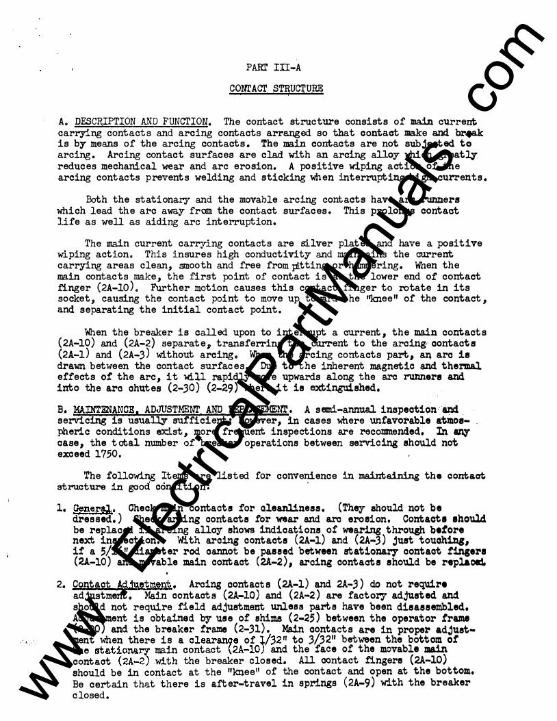
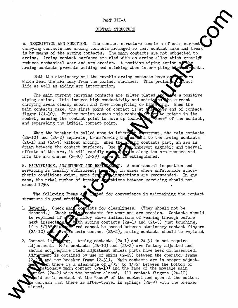
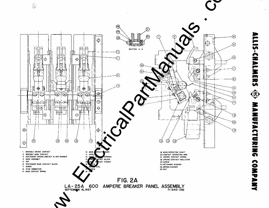
A.. DESCRIPTION AND FUNCTION. The contact structure consists of main current; carrying contacts and arcing contacts arranged so that contact make and break is by means o:f the arcing contacts. The main contacts are not subjected to arcing. Arcing contact surfaces are clad with an arcing alloy which greatly reduces mechanical wear and arc erosion. A positive wiping action o:f the arcing contacts p revents welding and sticking when interrupting high currents.
Both the stationar.r and the movable arcing contacts have arc runners which lead the a:rc away :from the contact surfaces. This prolongs contact life as well as aiding arc interruption.
The main current carrying contacts are silver plated and have a positive wiping action. This insures high conductivity and maintains the current carr,ring areas clean, smooth and :free :from pi..tting or hammering. When the main contacts make, the :first point o:f contact is at the lower end o:f contact :finger (2A-10). Further motion causes this contact finger to rotate in its socket, causing the contact point to move up toward the ''knee" of the contact, and separating the initial contact point.
When the breaker is called upon to interrupt a current, the main contacts (2A-10) and (2A-2) separate, transferring the current to the arcing·· contacts (2A-l) and (2A-3) without arcingo When the arcing contacts part, an. arc is drawn between the contact surfaces. Due to the inherent magnetic and t hermal effects of' the arc, it will rapidly move upwards along the arc runners and into the arc chutes (2-30) (2-29) where it is extinguished.
B. MAOOENANCE, ADJUST.MENI' AND REPLACEMENT. A semi-annual inspection and servicing is usually suf"ficient; however, in cases where unfavorable atmospheric conditions exist, more frequent in spections are recommended� In 8ZI:1 case, the total number o:f breaker operations between servicing should not exceed 17,50,
The :following Items are listed for convenience in maintaining the contact structure in good condition:
'
1, pener'*o Check main contacts for aleanliness. (They should not be dressed. ) Cheek aroing contacts f'or wear and a.rc eroeion , Contacte ehould be replaced if arcing alla,r shows indications of' wearing through before next inspection. With arcing contacts (2A-1) and (2A-3) just touching, if a 5/1611 diameter rod oannot be paseed between s\iatio:naey contact finsere (2.4.-10) and movable main contact (2A-2) 1 arcing contacts should be replace:L
2. Contact Ad.1U!�tmen.�. Arcing contacts (2A-l) and 2A-.3) do not require adjustment. Main contacts (2A-10) and (2A-2) are fact ory adjusted and should not require field adjustment unless parte have been disassembled, Adjustment is obtained by use of shims (2-2;) between the operator frame (2-20) and the breaker frame (2-.31). Main contacts are in proper adjust-
. . ment when there is a clearan9 e of l/32 11 to 3/3211 between the bottom o! the stationa� main contact �2A-10) and the face of the mo vable main oontaot ( 2A-2 ) with the breaker closed. All contact fingers (2A-10) should be in contact at the "knee" of the contact and open at the bottom..
Be certain that there is after-travel in springs (2A-9) with the breaker closed. www .
Elec
tricalP
artM
anua
ls . c
om
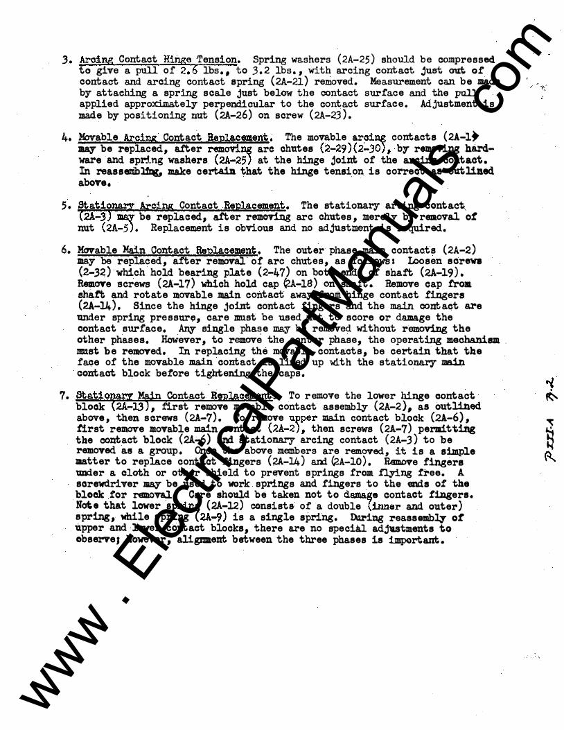
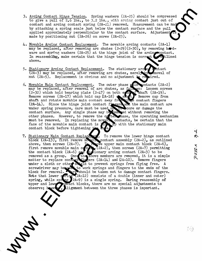
3. Arcing Contact Hinge Tension. Spring washers (2A-25) should be compressed to give a pull of 2.6 lbs,, to .3.2 lbs., with arcing contact just out of contact and arcing contact spring (2A-21) removed. ·Measurement can be made by attaching a spring scale just below the oontact surface and the pull applied approx:i..mately perpendicular to the contact surface. Adjustment is made by positioning nut (2A-26) on screw (2A-23).
4. Movable Arcing Contact Replacement� The movable ar�i� contacts (2A-l) may be replaced, a.:t'ter removi� arc chutes (2-29)(2-30), b;r removing hardware and spring washers. (2A-2;) at the hinge joint of' the arcing contact. In reassenibl1l:lg, make certa.iJl that the hinge tensi_on. is correQt ae outliaed. above.
;. stationa.rz Arcir!B Contact ReEla.cement. The stationary arcing contac� (2A-3) m.a.r be replaced, after removing arc chutes, merely by removal o! nnt (2A-5). Replacement is obvious and no adjustment is required.
6. Movable Main Contact Replacement. The outer phase main contacts (2A-2) may be replaced, a.:fter removal· of arc chutes, as follows: Loosen sor8VI (2-32) which hold bearing plate (2-47) on both ends of shaft (2A-19). Remove screws (2A-17) which hold cap C2A-1S) on shaft. Remove cap from. shaft and rotate movable main contact away from hinge contact .fingers (2A-J.4), Since the hinge joint contact fingers and the main contact are under spring pressur�, care must be used not to score or damage the contact surface. Any single pha�e may be removed without removing the other phases. However, to remove the center phase, the operating mechaniiUil . must be removed, In replacing the movable contacts, be certain that the face of the movable main contact is lined up "With the stationary main contact block before tightening the caps,
__ ,
"l 7. stationarz Main Contact Replacement� To r emove the lower hinge contact �
block (2A-l3) 1 first rellJOve movable contact assembly (2A-2), as outlined above, then serews (2A-7). To remove upper main contact block (2A-6), first remove movable main contact (2A-2 ) , then screws (2!-7) permitting � the contact block (2A.;.6) and stationary arcing contact (2A-3) to be � removed as a group. Onoe the above members are removed, it is a simple � :matter to replace cont:act fingers (�-14) am G2A-10), Remove fingers '" ader a cloth or other shield to prevent s prings from. !:cying free. A screwdriver ma.y be used to work springs and fingers to the ends of the
. block for removal. Care should be taken not to dama.�e contact fingers. Nate that lower spri� (2A-12) consists of a double {inner and outer) spring, while spring (2A-9) is a single spring. During reassemb!J' of upper and lower contact blocks, there are no specill adjv.stments to observeJ however, aligmnent between the three phases is important..
www . El
ectric
alPar
tMan
uals
. com

PART IV
SERIES OVERCDaqENT PROTECTIVE DEVICES
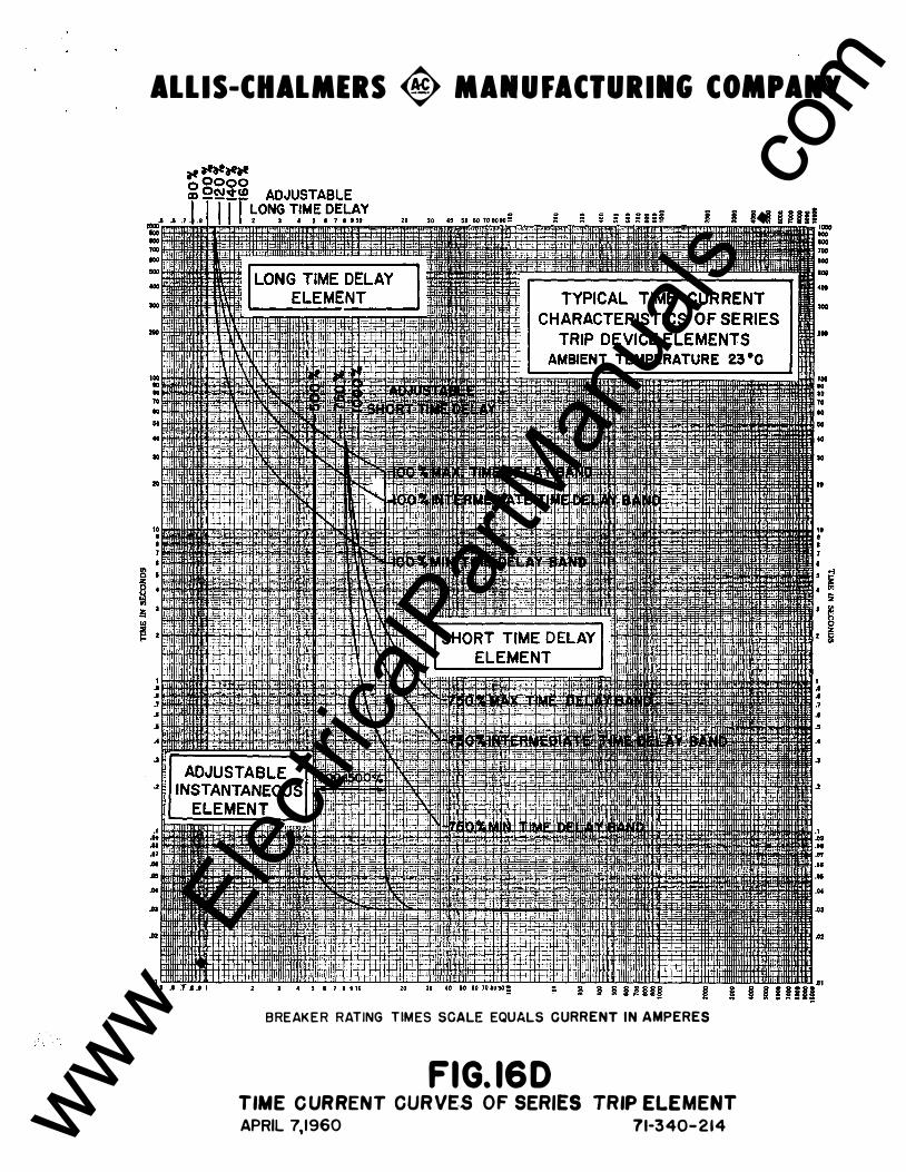
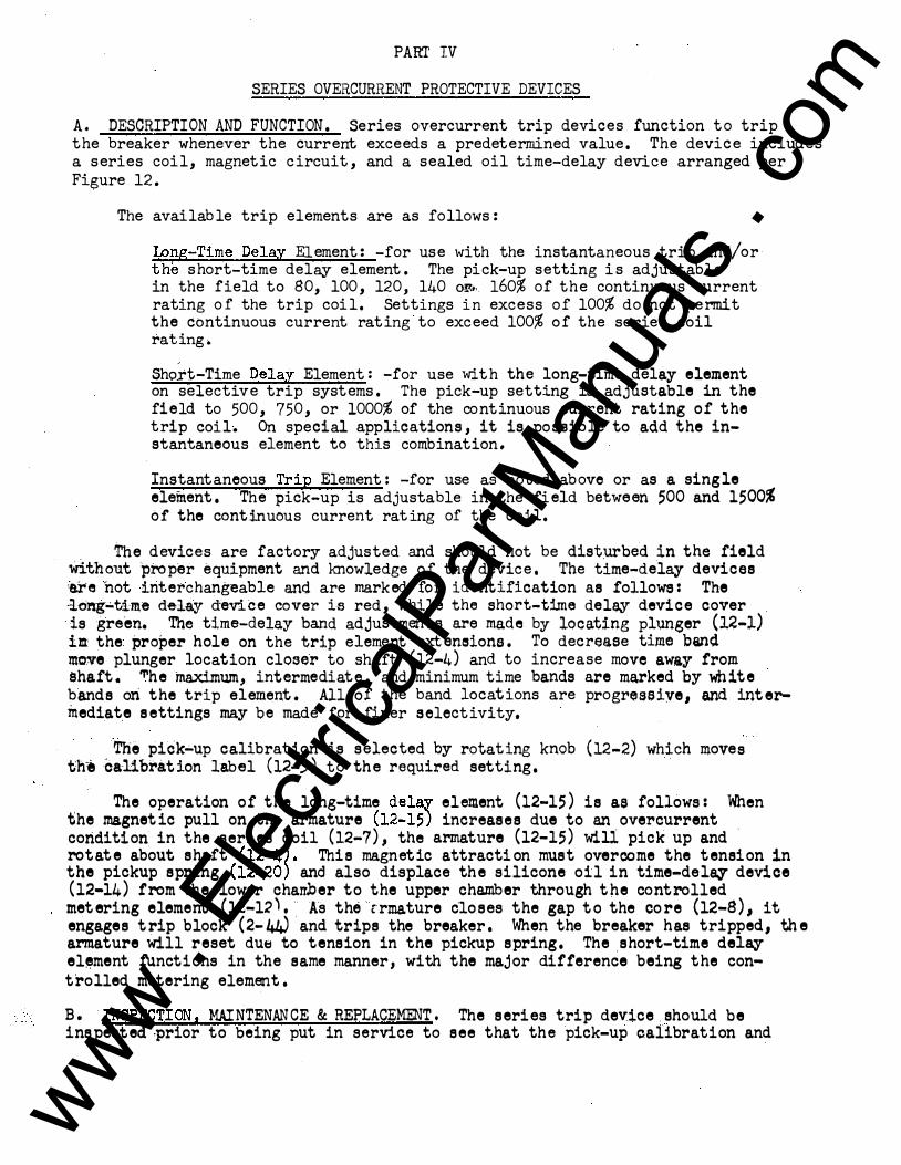
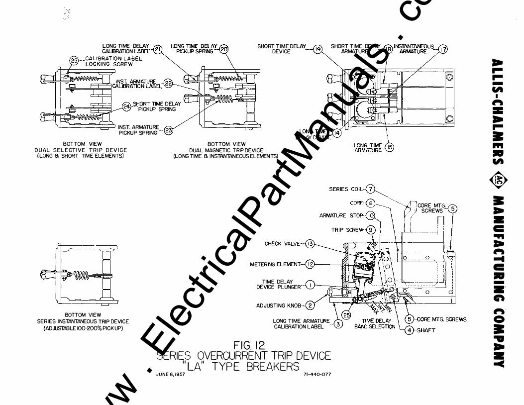
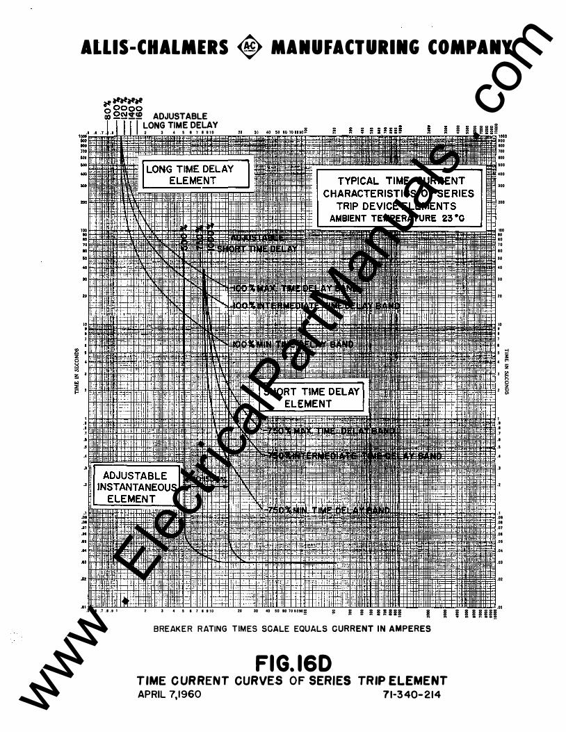
A. DESCRIPTION AND FUNCTION. Series overcurrent trip devices function to trip the breaker whenever the current exceeds a predetermined value. The device includes a series coil, magnetic circuit, and a sealed oil time-delay device arranged per Figure 12.
The available trip elements are as follows:
Long-Time Delay Element: -for use with the instantaneous trip and/or the short-time delay element. The pick-up setting is adjustable in the field to 80, 100, 120, 140 oF,t.. 160% of the continuous current rating of the trip coil. Settings in excess of 100% do not permit the continuous current rating to exceed 100% of the series coil rating.
-Short-Time Delay Element: -for use with the long-time delay element on selective trip systems. The pick-up setting is adjustable in the field to 500, 750, or 1000% of the co ntinuous current rating of the trip coil. On special applications, it is possible to add the instantaneous element to this combination.
Instantaneous Trip Element: -for use as noted above or as a single element. The pick-up is adjustable in the field between 500 and 1500% of the continuous current rat ing of the coil.
The devices are factory adjusted and should not be disturbed in the field without proper equipment iu+d knowledge of the device. The time-delay devices are hot interchangeable and are marked for ide ntification as follows: The -long-time delay device cover is red, while the short-time delay device cover is green. The time-delay band adjustments are made by locating plunger (12-1) in the proper hole on the trip element extensions. To decrease time band move plunger location closer to shaft (12-4) and to increase move away from shaft. "'he lnaximwn, intermediate, and minimum ti me bands are marked by wh ite bands on the trip element. All of the band locations are progressive, and intermediate settings may be made for finer selectivity.
The pick-up calibration is selected by rotating knob (12-2) which moves th·e calibration label (12-3) to the required setting.
The operation of the long-time dela,r element (12-15) is ae follows: When the magnetic pull on the armature (12- 1 5 ) increases due to an overcurrent condition in the series coil (12-7), the armature (12-15) will pick up and rotate about shaft (12-4). This magnetic attracti on must overcome the tension in the pickup spring (12-20) and also displace the silicone oil in time-del� device (12-14) from the lower charrber to the upper chamber through the controlled metering element (12-12'. -�As the -rrmature c'loses the gap to the co re (12-8), it engages trip block (2-44) and trips the breaker. When the breaker has tripped, the armature will reset due to tension in the pickup spring. The .short-time del� el•ment fUnctions in the same manner, with the major difference being the cont'rolled metering element.
B. INSPECTION, MAINTENANCE & REPLACEMENT. The series trip device ehould be inspected prior to being put in service to see that the pick-up calibration and
www . El
ectric
alPar
tMan
uals
. com
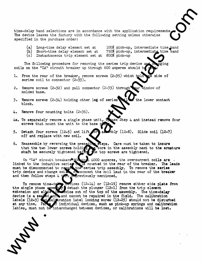
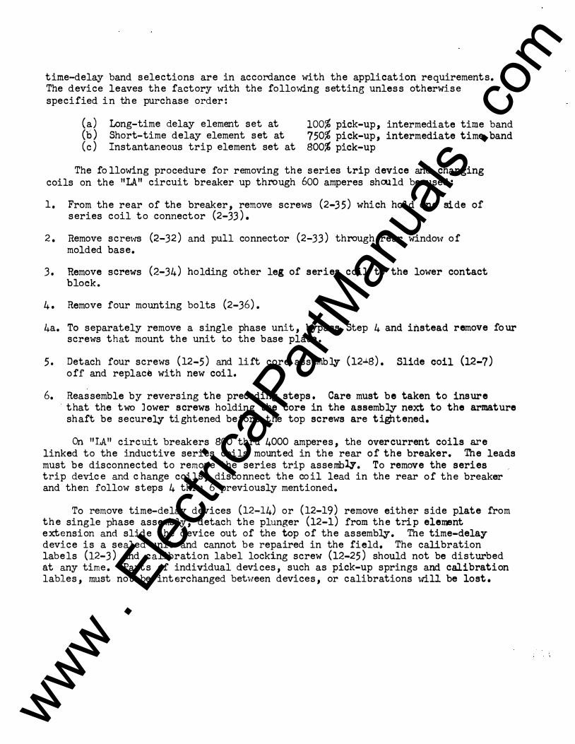
time-delay band selections are in accordance w ith the application requirements. The device leaves the factory 1-rith the following setting unless otherwise specif ied in the purchase order:
( a) Long-time delay element set at (b) Short-time delay element set at (c ) Inst antaneous trip element set at
100% pick-up, intermediate time band 750% pick-up, intermediate time band 800% pick-up
The fo llowing procedure for removing the series trip device and chang ing coils on the "l.A11 circuit breaker up through 600 amperes should be used:
1. From the rear of the breaker, remove screws (2-35) w hich hold one side of series coil to connector (2-33).
2. Remove screws (2-32) and pull connector (2-33) through rear window of mo lded base .
3. Remove screws (2-34) holding other leg of series coil to the lower contact block,
4. Remove four mounting bolts (2-36). 4a. To separately remove a single phas e unit, bypass Step 4 and instead remove four
ecrewe that mount the unit to the base plate.
5. Detach four ecr�n.,re (12-S) and lift core assembly (12-S). Slide coil (12-7) orr arid replace with new coil .
6. Reaaeemble by reversing the preceding eteps. Care must be taken to ineure · that the two Jower ecrewe holding the core in the aseembly next to the armature
ehatt b� eaourelr tightened before the top ecrewa are tightened , On "LA11 circuit breakers 800 thru 4000 ampere a, the over current coila are .. ,
linked to the inductive serie� coilf!l mounted in the rear of the breaker. The le.ada must be disconnected to remove the �eriee trip a3eemblr. To remove the aeriea trip devica and c hange coila, disconnect the coil lead in the rear of' the breaker and then follow eteps 4 thru 6 previouely mentioned,
To remove time-delay devices (12-14) or (12-19) remove either side plate trom th e single phaee assembly, detach the plunger (12-1) !rom the trip element extension and elide the device out o! the top o! the aaeembly, The time-delar de vice ie a eealed unit and cannot be repaired in the field. The calibration labele (12-3) and calibration label looking screw (12-25) ehould not be diaturbed at any time, Parte of individual devices , euch as pick-up eprings and calibration lables, nru.et not be interchanged between devion, or calibratione will be loet.
www . El
ectric
alPar
tMan
uals
. com
. ·� . '
PART V
THERMAL OVERCURRENT PROTECTIVE DEVICE
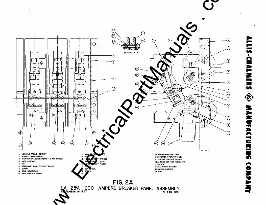
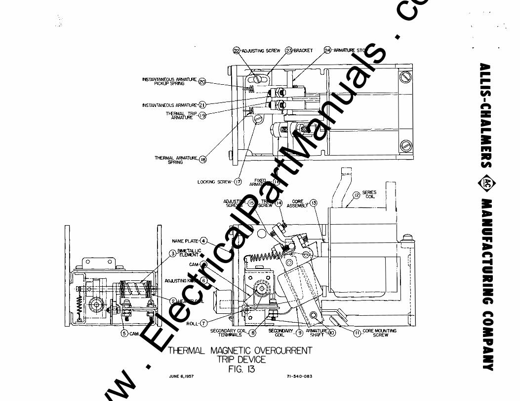
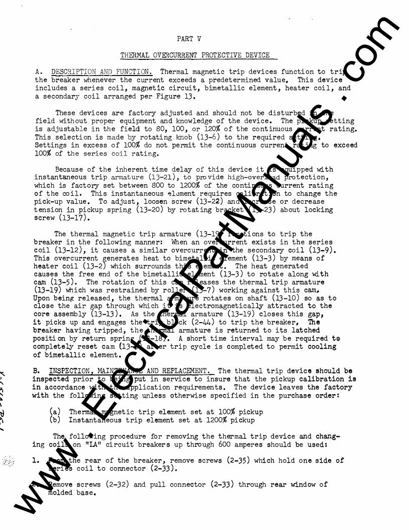
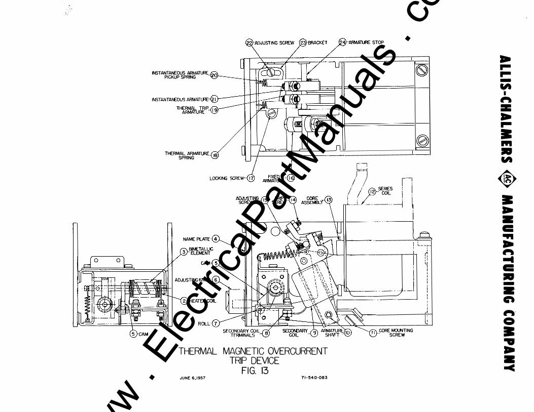
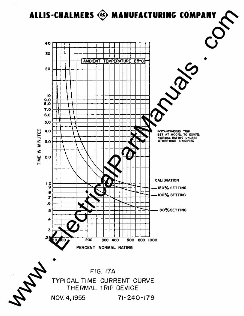
A. DESCRIPTION AND FUNCTION. Thermal magnetic trip devices functi on to trip the breaker whenever the current exceeds a predetermined value. This device includes a series coil, magnetic circuit, bimetallic element, heater coil, and a secondar,y coil arranged per Figure 13.
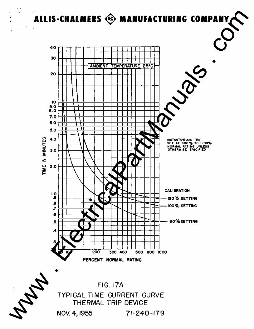
These devices are factory adjusted and should not be disturbed in the field without proper equipment and knowledge of the device. The pickup setting is adjustable in the field to 80, 100, or 120% of the continuous current rating. This selecti on is made by rotating knob (13-6) to the required setting. Settings in excess of 100% do not permit the conti nuous current rating to exceed 100% of the series coil rating.
Because of the inherent time delay of this device it is equipped with instantaneous trip armature (13-21 ) , to pzuvide high-overload protection, which is factory set between 800 to 1200% of the continuous current rating of the coil. This instantaneous �l�ment requires calibration to change the pick-up value. To adjust, loosen screw (13-22) and increase or decrease tension in pickup spring (13-20) by rotating bracket ( 13-23 ) about locking screw ( 13-17).
The thermal magnetic trip armature ( 13-19) functions to trip the breaker in the following manner: When an overcurrent exists in the series coil (13-12 ) , it causes a similar overcurrent in the secondary coil (13-9). This overcurrent �enerates heat to bimetallic element (13-3 ) by means of heater coil (13-2 ) which surrounds this element. The heat generated causes the free end of the bimetallic element ( 13-3 ) to rotate along with cam (13-5). The rotatio n of this cam releases the thermal trip armature (13-19) which was restrained by roller (13-7 ) working against this cam. Upon being released, the thermal armature rotates on shaft (13 -10) so as to close the air �ap through which it is electromagnetical� attracted to the core assembly (13-13 ) . As the thermal armature ( 13-19) closes this gap , it picks up and engages the trip block (2-44) to trip the breaker, 'lhe "
breaker having tripped, the thermal armature is returned to its latched positi on by return spring ( 13-18) . A short time interval may be required te completely reset cam (13-5) after trip cycle is completed to permit cooling of bimetallic element.
B. INSPECTION, MAINTENANCE AND REPLACEMENT. The thermal trip device should be inspected prior to being put in service to insure that the pickup calibration is in accordance with the application requiremen ts. The device leaves t he factory with the following setting unless otherwise specified in\ the purchase order:
(a ) Thermal magnetic trip element set at 100% pickup (b) Instantaneous trip element set at 1200% pickup
The following procedure for removing the th�mal trip device and changing coils on "LA" circuit breakers up through 600 amperes should be used:
l. From the rear of the breaker, remove screws (2-35) which h old one side ot series coil to connector (2-33).
2. Remove screws (2-32) and pull connector (2-33) through rear window of molded base. www .
Elec
tricalP
artM
anua
ls . c
om

3. Remove screws (2-34) holding other leg of series coil to the lower contact block.
4. Remove four mounting bolts (2-36 ) .
4a. To separate� remove a single phase Unit, ty-pass step 4 and instead remove four screws that mount the uriit to the base plate.
5 . Detach four screws (13-11) and lift core assemb� (13-13). Slide coil (13-12) off and replace with new coil•
6. Reassemble by reversing the preceding steps. Care must be taken to insure that the two lower screws holding the core in the assembly next to the armature shaft be secure� tightened before the top scre\oJ"S are tightened.
On 11U." circuit breakers, 800 through 4000 amperes, the overcurrent coils are linked to the inductive series coils mounted in the rear of the breaker. The leads must be disconnected to remove the series trip assembly. To remove the thermal trip device and change coils, disconnect the coil lead and follow steps 4 through 6 noted above. Other parts of the device should not be removed or disassembled since to do so l\rill disturb the calibration.
www . El
ectric
alPar
tMan
uals
. com
AUXILIARY--( 5 SWITCH
INTERLOCK--( I TRIP BAR
i I
SHLNT TRP DEVICE ATTACHMENT (LEFT- HAND VIEW)
6 1--A�s:;��f�v SWITCH
10 )--UNOERVOLTAGE TRIP
ATTACHMENT
18 )--BREAKER NAMEPLATE
PROVISION-FOR PADLOCK
�i ·� l
��
·E£;�1-Ill ��i����l-· �t- .. ':'� ...
""+ �1-. '+ i!<l-,�1
8 - ��-� -lH��� �f�l
'=--=-----' �
LIFTING BOLT {REMOVABLE) PROVIDED FOR THIRD POINT BREAKER LIFT
!41t-t3� HdlES
Oi .. , ... I'+ ��-
" ..,_ '.
;;;t-
.. i 'OliO 0 o 0
� + I
13 t- ii
20!.7 .. -r----
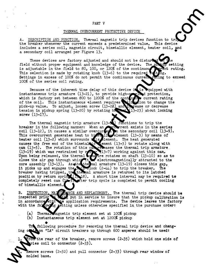
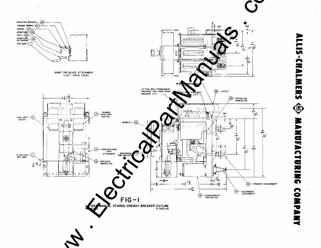
FIG-I LA-25A MANUAL STORED-ENERGY BREAKER OUTLINE, MAY �1960 71-540-110
16)--0VERCURRfNT TRIP DEVICE
a; iiiUi .. 1:1-
... ... ... .. "'
'I � = ... ... • ... • "'
� II .. • • ... ... � .... • • -• eft � 0 • .. .. • -c
www . El
ectric
alPar
tMan
uals
. com

www . El
ectric
alPar
tMan
uals
. com
AlLIS·CHA�MHS <$>-�MANUFACTURI IG COM PANY
I. Cl.OSI'«i SPRINGS
2. MAMJAl TRIP SPRJNG 3. MAMJAl TRIP BUTTON
4. ROCKING LINK
5. LAT'Qi PIN 6. YOKE
7. SHAFT
8. MAIN CLDSING CAM
9. OPENING SPRINGS
IQ SHAFT
I I. RATCHET
12. PN
13. CAM
14. LINK
1!5. LINKS
16. PAWL
17. TORSION SPRING
18. CLOSII«i tWolOLE
J; (:f) -1- -1-r:±:\ (��; + r
-1- -1-
19. OPEN -CLOSE lf<.OICATOR
20. OPERATING MECHANISM FRAME
2 L INDICATOR LINK
2 � SPRING
23 STUD
24. SCREW
25. CONTACT ADJUSTING SHIMS
26. ARC GHUTE SUPPORT (LDWER)
27. SCREW
28. ARC CHUTE SUPPORT (UPPER)
29. ARC CHUTES (UPPER)
30. ARC CHUTES (LOWER)
3 L PANEL ASSEMBLY
32. SCREWS
.3SCR.:WS
34. CONNECTORS
�.SCREWS
36. SCREWS
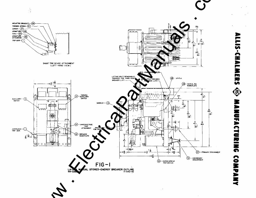
FlG.2 LA-25A MANUAL STORED-ENERGY MAY 13,1960
37. SCREWS
38. OVERCURRENT TRIP DEVICE
39. "l"RfP LATCH ADJUSTING SPRING
4'-. TRIP LATCH ADJUSTING SCREW
4 I. NEEDLE BEARING
42. MANUAL TRIP BLOCK
43. PROP LATCH SPRING
44. TRIP LATCH
45. TRIP BLOCK
46. SECONDARY TRIP LEVER
47 BEARING PLATE
48 PRIMARY TRIP LEVER
49. PROP LATCH
50. MAIN TOGGLE LINK
5 I. CAM FOLLOWER
52. CONTACT OPERATING ARMS
53. BUSHING
BREAKER 71-540-111 www .
Elec
tricalP
artM
anua
ls . c
om

www . El
ectric
alPar
tMan
uals
. com
I r-- I .- r- f= r-
0 0
iJ � $
r-
(' .. I J;� '
[f=t:tJ t--r--
1 �� ro -- �r::-; � '---1. _r-+l-1-(..j...). �
� f..{+) k+l � �-<ll � � �r -$- � � r-
:rrr ·+
-$ 18 18 20
I. MOVABLE ARCING CONTACT
2. MOVABLE MAIN CONTACT
3. STATIONARY ARCING CONTACT 8 ARC RUNNER
4. BASE ASSEMBLY
s. NUT
6. STATIONARY MAIN CONTACT BLOCK
7. SCREW
8 STUD CONNECTOR
9. MAIN CONTACT SPRING
r F' n_ -$ ,-
( �
, .-
'J
rr::=:; I I : -:-t"� t I '1-' I I __[ 1-----J I I I ' I I I I ' I I I I '
I
i
'!- ' : I r-- I I
I I
'
(
I \
'
r( � '-I. � � 1.-r-
I 1 I I I I I I --
-4M v +I- W'
�kr+l ,.It -- I ----
t!+ . .,. j_J,_ Jj � �}-
-$-� � I--- I I : ] I I I
i • 1 7
$-i L-....1 10. MAIN CONTACT FINGER
II. SHIELD
12. HINGE CONTACT SPRINGS
13. HINGE CONTACT BLOCK
14. HINGE CONTACT FINGER
15. SCREW
16. SERIES COIL
17. SCREW
18. CAP
SECTION
19. MAIN OPERATING SHAFT
2Q CONTACT OPERATING ARM
21. ARCING CONTACT SPRING
22. ARCING CONTACT INSULATOR
23.SCREW
24. RETAINING WASHER
25. SPRING WASHER
26. NUT
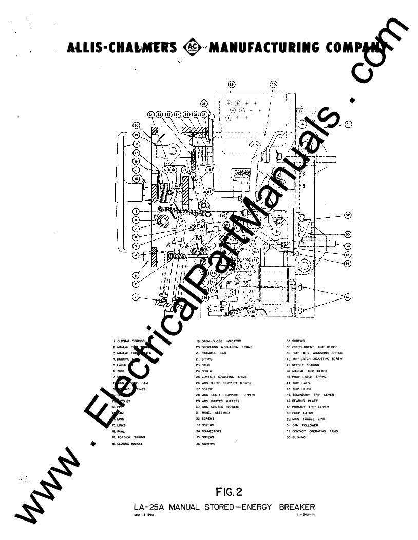
FIG. 2A LA- 25A 600 A MPERE BREAKER PANEL ASSEMBLY SEPTEMBER 16, 1957 71-540-092
... ... ... -"'
I " :II ... ... • Ill • "'
1:1
-
www . El
ectric
alPar
tMan
uals
. com

www . El
ectric
alPar
tMan
uals
. com
AlliS-CHALMERS � MANUFACTURI NG COMPANY
I- (0 &3 (0 rt)
'
z 0 v z (\J 0 •
-(.) "-(f) -0 I
>->-I--
>-'
(X) Oo::
I
a::_J a:: _J �w <(� <(
<(QJ z(!)
co 2 • 0� zg -
0� :E (!) oLL 8m a:: zw w w ocn (/) .....
lL ocn W<( (f)
(X) _J 10 <( 0') -(.) ... -
- I'() a.. >->- _J J- =>
-:>
www . El
ectric
alPar
tMan
uals
. com

www . El
ectric
alPar
tMan
uals
. com

LONG TIME DELAY CALIBRATION LABE[-(21 LONG TIME DELAY-{2Q'
PICKUP SPRING- ·
25)--CALIBR A T I O N LABEL LO CKING SCREW
24)_$tiORT TIME DELAY PICKUP SP RING
!"'= =/ \ \ I I I INST. ARMATURE (23 P ICKUP SPRING ·--
BOT T OM VIEW BOT T OM V IEW
_;
SHORT TIME DELAY ( 19 DEVICE -- SHORT TIME DELAY ARMATURE -
p uA L S E L E CTIVE T RI P DEVI C E (LONG 8r SHORT TIME ELEMENT S)
DUAL MA GNETIC TRIP DEVICE (LONG T IME 8r INSTANTANEOU S ELEMENT S)
ARMATURE
MET ERING ELEMENT---( 12) Hl �
,r-1 · : •CORE MT G . . �7 SCREWS-
,· ( 1'1 ! : : : --- ----1 I
TIME DELAY - - -- --- I DEVICE PLUNGER-- I
o
BOT T OM VIEW SERIES INSTANTANEOUS TRIP DEVICE
(ADJUSTABLE 100-200% P ICKUP)
ADJ USTING KNOB---( 2
FIG.12
25 LONG TIME ARMATURE ?-:\ '-../ TIME DELAY CALIBRATI ON LABEL --� BAN) SELECTION
SERIES OVERCURRENT TRIP DEVICE "LA" TYP E BREAKERS
JUNE 6,1957 71-44Q-077
5 }-CORE MT G. SCREWS
-
-
www . El
ectric
alPar
tMan
uals
. com

www . El
ectric
alPar
tMan
uals
. com
ALLIS-CHALMERS � MANUFACTURING COMPANY
BREAKER RATING TIMES SCALE EQUALS C URRENT I N AMPERES
FIG.I6D TIME CURRENT CURVE.S OF SERIES TRIP ELEMENT APRIL 7,1960 71-340-214 www . El
ectric
alPar
tMan
uals
. com

www . El
ectric
alPar
tMan
uals
. com
THERMAL ARMAT�-( IS. SPRING
��-(1
��W'-{15
THERMAL MAGNETIC OVERCURRENT TRIP DEVICE
FIG. 13 JUNE 6,1957 71-!540-083
·ARMJmH: STOP
[J .r) ,--l I SERIES I I //@--cOIL ! j
I j_L_ ______ � � . �--
! '---.-' '
-�-1 �
I 1 j, ) CORE MOIJijTING II-- SCREW
.. .. .. -tit
I " = .. .. • ... • tit
� • .. • c: ... .. " ... c: • -• C\ " 0 • .. .. • --=
www . El
ectric
alPar
tMan
uals
. com

www . El
ectric
alPar
tMan
uals
. com
..
ALLIS-CHALMERS � MAIUFACTURIIG COMPANY
C{) w ..... ::::> � :E iii: w :E i=
40
30
20
10 9.0 8 . 0 7.0 6 . 0 5.0
4.0
3.0
2.0
1 .0 .9 .8 ;r .6 .5
.4
3
\ \ \ \ \ \ \ \ \ \
\ \ \ \ \
\
AMBIENT TEMPERATURE 25°C
\ \ \
1\\ \ �\ � " ' "' " ........ i'-.. r.... ....
' r--. t-' r--.�
t"-..... -r-r-... t.... " -1-
1-
t-
INSTANTANEOUS TRIP
SET AT 800% TO 1200% NORMAL RATING UNLES S OTHERWISE SPECIFIED
CALI BRATION
- 120 o/o SETTING - 100°/o SETTING
- 8 0 o/o SETTI NG
.25 80 100 200 300 400 600 800 1000
PERCENT NORMAL RATING
FIG. 17A TYPICAL TIME CURRENT CURVE
THERMAL TRIP DEVICE NOV. 4,1955 71-240-179 www . El
ectric
alPar
tMan
uals
. com

• www .
Elec
tricalP
artM
anua
ls . c
om
) -�/
'P, Installation, Care and Operation
of Circuit Breakers and Accessories
TYPE IA-l5A and LA.-2SA MANUAL STORED-ENEIDY
AIR CIRCUIT BREAKER
BOOK BWX-6559
These instructions are not intended to cover all details or variations that may be encountered in connection with the installation, operation, and maintenance of this equipment. Should additional information be desired contact the Allis-Chalmers Mfg. Company.
41115·(H41M ER5 M f6. (0. BOSTON WORKS • BOSTON • MASS.
www . El
ectric
alPar
tMan
uals
. com

www . El
ectric
alPar
tMan
uals
. com

AlLIS·C:HALMERS � MANUFACTURING .COMPANY
PAm' I.
PARr n-A.
PART III-A.
PART IV.
PART V. ·
PIGUD l PIGUIE 2 PICJU!I.U PIGUU 8 PIGUIBl l2 FIG'URI 16D FIGURil3 FIGtnm l7A
INDEX TO INSTRUCTION :OOOK COVERING
TYPE LA.-25A MANUAL 'STORED-ENEmY BREAKER
GENERAL INFORMATION
A. IJITRODUCTION B. W.A.RRANTY C. RECEIVING AND INSPECTION FOR DAMAGE D. STORAGE E. CAUTIONS TO BE OBSERVED F. INSTALLATION G. MAINTENANCE
OPERATING MJIDHANISM
A. DESCRIPTION AND FUNCTION B. MAINTENANCE CLOSOO C. MAINrENANCE AND ADJUSTMENT
CONTACT STRUCTURE
A. DESCRIPTION AND FUNCTION B. MAINTENANCE 1 ADJUSTMENT AND REPLACEMEN!'
. SERIES OVERCURRENT PH:>TECTIVE DEVICES
A. .DESCRIPTION AND FUNCTION B. INSPECTION, MAINTENANCE AND REPLACEMENT THERMAL OVERCURRENl' PROTECTIVE DEVICE A. DESCRIPTION AND FUNO'l'ION B. INSP:mTION, MAINl'ENANCE AND REPUCEMEN'l'
LIST OF ILLUSTW.TIONS
BDAKER. Otn'LINE S'l'OBED-EN'DlY BREAKER PAREL ASSEMBLI SECOND.ABr DISCONNECT SERIES 'l'BIP DEVICE SDIES TiiP CURVES THERMAL TIUP DMOE THERMAL '!'RIP CURVES
www . El
ectric
alPar
tMan
uals
. com

L ·j \_:
www . El
ectric
alPar
tMan
uals
. com
Instructi ons For the Installat i on and Operation
of Allis -Chalmers Type "LA"
Low Voltage Air Circuit Breakers and Auxiliary Eq�ipment
Part I GENERAL INFORMATION
A . INTRODUCTI ON . The type "LA" air circuit breakers may b e used i n metal enclosed swit chgear , on open type switchbc ards , or s eparately mounted in individual housings . All "LA" breakers are c ompletely assembled , t ested and calibrated at the factory in a vert ical pos it ion and must b e s o installed to operat e properly. Customer ' s primary connecti on s should be adequat ely braced against the effects of short-circuit current s to prevent overstressing the breaker t erminals .
B . WARRANTY. Allis-Chalmers ' "LA" air circuit breakers are warranted to b e free of defects i n mate rial and workmanship for a period of one year aft er deliver,y to the original pur chaser. Thi s warranty is limited t o t h e furnishing o f any part which t o our satisfaction h as been proven defect ive . Allis-Chalmers will not in any case assume responsibility for allied equipment of any kind .
C. RECEIVING AND INSPECTION FOR DAMAGE . Immediat ely upon receipt of th is equiPment , carefully remove all packing t races and examine part s , checking th em againet the packing list and noting any damages incurred in transi t . I f euch i B disclosed, a damage clai m should b e filed at once with the transportation company and AllisChalmers notifi ed .
D . STORAGE . When breakers are not t o be put int o immediat e us e , they sh ould be wrapped or c overed to provide protection from plaster , concret e dust and other foreign matt er . Breakers should not b e exposed to the act i on o f corrosive gases and moisture . In areas of high humidity or t emperature fluctuat ion s , space heaters or th e equivalent s hould be pro vi ded . Circuit bre aker s should b e handled careful� at all times .
E. CAUTIONS TO BE OBSERVED IN THE INSTALLATION AND OPERATION OF "LA" CI RCUIT· BREAKERS . 1 . D o not att empt t o operat e breaker o r insert in cubicle unti l all packing traces
have been removed .
2. Read Instructi on Book before making any c hanges or adjustment s on the breaker .
3 . Do not int erchange part s of trip devices - to d o eo may change calibrations.
4. On manually operat ed breakers , always operat e closing ha ndle quickly and decis ively .
; . Check current rat ings and serial numbers against single line diagram t o assure that break er s ar e properly located in switchgear at inst allati on ..
6. Check the alignment o f t he secondar,r disconnect f1 ngers to insure against misalignment due to pos sible dj storti on of f1 ngers during sh ipment ani handling .
7. Onc e the breaker is energized , it shoul� not be t ouched , exc ept for operating, sinc e most of th e co mponent part s are aJ so energi z ed .
www . El
ectric
alPar
tMan
uals
. com
F . INSTALLATI ON . The "LA " air circuit breaker is completely adjust ed , t ested , and inspe ct ed at the factory b e fore shipment and no additional adjustment should be neces sary when installing . However , a careful check should be made to be cert ai n that shipment and storage has not resulted i n damage or change of adjustment . Circuit breakers should b e installed in a c lean , dry , well-ventilated place in which th e atmosphere is free from destructi ve acid or alkali fumes . Mount open-type breakers high enough to prevent injury to personnel either fr om circuit int errupti on or from moving part s during aut omatic opening of the breaker. Allow suffici ent space to permit acc e s s for cleaning and inspecti on . Also allow sufficient clearanc e t o insulating barri er above the breaker to prevent damage from arci ng. Be fore installing , make certain that the breaker contact s ar e in the open pos ition .
After the breaker i s installed in positi on , clo se i t manually to che ck proper functionin� o f the mechanism and c ontacts . ( CAUTION : }�KE SilltE CIRCUIT I S NOT ENERGIZED . ) During the clos ing operat ion , obs erve that the contact s move freely without int erference or rubbing between movable arc ing co ntact s and part s of the arc chut e s . Refer to Part II of the Instructi on Book for a det ai led descripti on o f the cir cu it breaker operating characteri stics .
Trip unit s and ac cessory devices should receive a thorough che ck prior t o placing t h e breaker in s ervi ce t o be c ertain that adjustments are proper and part s are not damaged .
Cubicle mounted breakers of the drawout type are equipped v<ith a dra\vout int erlock to prevent movement of a closed breaker into or out of the " CO NNECT " position . See Part I I o f the Instruction Book �or a description of the int erlock . Its operation should be checked before the breaker is energiz ed.
Upon completion of the installation inspecti on , the breaker is ready to be energi z ed after the co nt rol wiring , if any, is checked and the insulation t est e d .
G . MAINTENANCE. Occasional checking and cleaning of the breaker wi ll promot e long and troub le-free s ervic e . A periodic inspection and servicing should b e included in the breaker maint enance routine .
Needle bearings are packed 1\rith a special lubricant and should require no further attention . Bearing pins and oth er s liding or rotat ing areas shou ld be wiped with a light film of " Aero Lubriplat e " (Manufactured by Fi ske Brothers Refining Co . ) . Gr easing s hould b e do ne with care becaus e exc ess grease t ends to c o llect dirt which in time might make operation sluggish and affect the dielectric strength of insulating member s .
I f th e circuit breake r i s not operat ed during ext ended peri ods , the breaker should not remain in eith er the closed or open pos iti on any longer than six month s . l1aint enance opening and clos ing operations s hould b e made to insur e freedom o f movement of all parts .
� t'� \;"'-.. � I
� �
i- - ...;\ t ' !
www . El
ectric
alPar
tMan
uals
. com
� ..... � �
� '
PART I:I-A
OPERATING }�HANISM
A. DESCRIPTION AND FUNCTION . The operating mecha..lism is the medium used to transmit power from the stored-energy closing springs to the contact structure to close the breaker. It is a 11trip-free11 mechanism; that is the breaker contacts are free to open at any time, if required, regardless of the position of the mechanism or the force being applied.
When the circuit breaker contacts are open, the operating mechanism is in the 11trip-free 11 position. Clockwise rotation of the closing handle ehgages pin (2-12) with cam (2-13) and rotates the cam against the roller attached to main closing cam (2-8) . This cam is moved downward by continued rotation of the closing handle thus compressing the charging springs through yoke (2-6) . As main closing cam (2-8) is driven downward , the lower end of main toggle link (2-50) is free to move to the left . This permits the latches to reset . The springs reach the fully-charged position at. the high point of the cam surface on cam (2-13) . When the roller rides over the high point of the cam surface, the energy in the springs is released. Main closing cam (2 .... 8) is raised against cam follower (2-51) and moves the top of main toggle link (2-50) to the right , thus closing the breaker contact s . Prop latch (2-49) engages latch pin (2-5) in main closing cam (2-8) holding the linkage in the latch position.
Opening of the breaker is acco�plished by the release of trip latch ( 2-44) by action of various trip devices or the manual trip button. Trip levers ( 2-46) and (2-48) , which are biased lat ches, are thus rel�ased and permitted to rotat e clockwise. Tne lower end of main toggle link ( 2-50) is now free to move to the right , permitting the force of the stationary main contact springs and springs (2-9) to move the top of this link t o the left , thus opening the breaker contacts .
B. MAINTENANCE CLOSING . The following method should b e used for maintenance closing the breaker during service inspections. The breaker should be out of service, and care must be taken to keep hands clear of the contact structure and other moving part s .
1 . Remove closing handle and breaker front cover .
2 . Move top o f pawl ( 2-16) to the left thus disengaging it from ratchet ( 2-lV.
3 o Replace closing handle and rotat.e it slow}y in t he clockwise direction ob-s erving trip latch ( 2-44) , secondary trip lever (2-46) , and primary trip lever (2-48) at the same time .
4. Continue to rotat e the handle clockwise� while holding it firmly, until the lat ches reset .
5 . At this point , r-everse the direction of handle rotation to counterclockwise. The handle will now be resisting the force of the s tored-energy closing springs and must be held firm1y and moved sl.ow}y.
CAUTION: This is a critical point in the direction of handle rotation. Rotation in a clockwise direction beyond the point where the lat ches just reset will cause th e breaker to close quickly as in a normal closing operation.
6 . As the handle is rotated counterclockwise , the contacts will move tov.erd the closed position ��d at the same time the energy in the stored-energy spr� will be gradually released. (If the contact s do not move during thi s step, it is an indication tb.at the latches have not reset . See step #4) .
www . El
ectric
alPar
tMan
uals
. com
7.
8.
When the contacts are fully closed, prop lat ch (2-49 ) will ;Latch on pin (2-5 ) . ( If the prop latch does not engage readily, a screwdriver can be used to raise yoke (2-6) slightly to as sist in lB.tching. )
It will be necessar.y to actuate the red trip button to open the breaker contacts .
9 . Before the cover can be replaced, pawl ( 2-16 ) must be moved to the right .
C. MAINTENANCE AND ADJUSTMENT . A semi-annual inspection and servicing is usually sufficient ; howeveri in cases where unfavorable atmospheric conditions exist, more frequent inspections are recommended. In any case, the total n� ber of breaker operations between servicing should not exceed 1750.
The following items are listed for convenience in maintaining the operating mechanism in good condition:
1. Trip Latch Ad,justment.. Trip latch (2-44) should have a tripping force of 2 to 6 ounces , a s measured at right angles to a 3/411 radius (pulling in line with the centerline of screw (2-40) . Force may be changed by positioning slotted end of spring (2-39 ) clockwise to decrease tripping force and counterclockwise to increase the tripping force.
2 .
3 .
4.
J •
Trip latch (2-44) engagement on secondary trip lever (2-46 ) roll should be 3/16" ± 1/64. Measurement is from the leading edge of trip latch face to the mean line of contact on the trip lever roll. Adjustment is obtained by the positioning of a fixed stop in the mechanism frame.
Trip Latch Roll Adjustment. Trip latch roll on screw (2-40) should have 1/3211 clearance (adjusted to the nearest turn) to trip block ( 2-45 ) with the trip block against its stop. Adjustment is obtained by positioning screw (2-40) .
Operating Mechanism Removal. The operator may be removed from the breaker by disconnecting opening springs (2-9 ) and contact operating arms ( 2-52) , and removing screws ( 2-24) , carefully noting number of shims (2-25 ) under each screw. Shims (2-25) are used to adjust main contacts ( see Part III ) and must not b e changed for any other reason. \'llien reassembling, the mechanism should be in the trip-free position. After reassembly, ch eck trip latch adjustment s and main contact adjustments . Check mechanism for ease of operation and freedom from binds .
Yoke Adjustment . With the breaker closed and latched, the nut on the threaded rod of yok� (2-6 ) should be flush -vri.th the bottom plate.
Interlock Adjustment . Cubicle mounted breakers of the drawout type are equipped with a drawout interloak. If a. closed breaker is racked in toward 11 connect position, 11 it should trip shortly after it passes the "test position" indicator. It will then be impossible to c lose the breaker until it reaches the 11connect position. 1 1 As a closed breaker is racked out , it should trip after approximately 5/1611 travel, and it will be impo ssible to close the breaker again until the 11test position11 is reached.
If the interlock does not function as described, adjustment may b e made by positioning the acorn nut of the interlock plunger.
'"" � ""
I �
'J
www . El
ectric
alPar
tMan
uals
. com
PAID' III-A
CONTACT STRUCTURE
A. DESCRIPTION AND FUNCTION. The contact structure consists of main current carrying contacts &�d arcing contacts arrar�ed so that contact make ��d break is by means of the arcing contact s . The main contact s are not subject ed t o arcing . Arcing contact surfaces are clad with an arcing alloy which greatly reduces mechanical wear and arc erosion. A positive wiping action of the arcing contacts p revent s welding and sticking when interrupting high current s .
Both the stationary and the movable arcing contact s have arc runners which lead the aN! away from the contact surfac es . This prolongs contact life as well as aidir,g arc interruption.
The main current carrying contact s are silver plat ed and have a positive wiping action . 'I'his insures high conductiv-ity and mair..tains the current carrying areas clean9 smooth and free from pLtting or hammering . When the main contacts make 9 the first point of contact is at the lower end of contact finger (2A-10) . Further motion causes this contact finger to r'Otate in its socket. , causing the contact point to move up toward the "knee 11 of the contact , and separating the initial contact point .
When the breaker is called upon to irrt. errupt a current , the main contacts (2A-10 ) and (2A-2) separat e � t ransferring the current to the arcing. contact s (2A-l) and (2A-3 ) without arcing . Whe� the arcing contact s part , an arc i s drawn between the co::-ttact surfac es . Due t o the irl.herent magnetic and thermal effect s of the arc , it will rapidly mov-e upwards along the arc r·u.nners and into the arc chut es (2-30) (2-29) where it is exting�shed .
B . MAINTENANCE2 AD�JUSTMENT AND REPLACEMENT . A semi-ann-;J.al inspection and servicing is usually sufficient ; however, in cas es where unfa7orable atmospheric conditions exist , more frequent inspections are recommended. In any case , the t otal number of breaker operations b etween servicing should not exceed 1750.
The following Items a.re listed for convenience in maintaining the contact structure in good condition �
1. GeneraL Check main contact s for cleanlines s . (They should not b e dressedo ) Cheek arcing contacts for wear and arc erosion. Contact s should be replaced if arcing alloy shows indications of wearing through before next. inspectiono With arcing contact s (2A-l) and (2A-3 ) just touching, if a 5/16 " dic:.meter rod cannot be passed between stationary contact fingers (2A-10) and movable main cont act (2A-2 ) 9 arcing contact s should be repla�
2. Cont act Adjustment . Arcing contact s (2A-l) and 2A-3 ) do not require adjustment o Main contact s (2A-10) and (2A-2 ) are factory adjust ed and should not require field adjustment unless part s have been disassembled. Adjustment is obtai."'l.ed by use of shims (2-25 ) between the operator frame (2-20 ) a.�d the breaker frame (2-31) . Main contacts are in proper adjustment when there is a clearance of l./3211 to 3/3211 between the bottom of the stationary main contact ( 2A-10) and the face of the movable main contact (2A-2 ) with the breaker .:losed. All contact fingers (2A-10) should b e in contact at t.he 111mee11 of the contact and open at the bottom. Be cert. ain t.ha.t. there i.s aft er-travel in springs ( 2A-9 ) with the breaker closedo www .
Elec
tricalP
artM
anua
ls . c
om
3 . Arcing Contact Hinge Tension. Spring washers ( 2A-25 ) should .be compres sed to give a pull of 2 . 6 lbs . , to 3 . 2 lbs . , •vith arcing contact just out o f c ontact and arcing cont act spring (2A-2l ) removed. Measurement can b e made by attaching a spring scale just below the contact surfac e and the pull applied approximately p erpendicular to the contact surface . Ad justment is made by positioning nut ( 2A-26) on screw ( 2A-23 ) .
4 . MOvable Arcing Contact Replacement . The movable arcing contact s ( 2A-l) may be replaced , after removing arc chutes ( 2-29 ) (2-30) , by removing hardware and spr:i.ng washers ( 2A-25 ) at the hinge joint of the arcing contact . In reassembJ.:fng, make certain that the hinge tension is correct as outlined above .
5 . Stationa Arci Contact Re lacement . The stationary arcing cont act 2A-3 may be replaced , aft er removing arc chutes , merely by removal of
nut ( 2A-5 ) . Replacement is obvious and no adjustment is required .
6. Movable Main Contact Replacement . The out er phase main contact s ( 2A-2 ) may be replaced , aft er removal of arc chutes , as follows : Loosen s crews ( 2-32 ) which hold bearing plat e ( 2-47 ) on both ends of shaft ( 2A-19) . Remove screws ( 2A-17 ) which hold cap �A-18) on shaft . Remove cap from shaft and rotat e movable main contact away from hinge contact fingers (2A-14) . Since the hinge joint contact fingers and the main cont act are under spring pressure, care must be used not to score or damage the cont act surface . Any single phase may be removed without removing the other phase s . However , to remove the center phase � the operating mechanism must b e removed. In replacing the movable contact s , be certain that the face of the movable main cont act is lined up �th the stationary main cont act block before tightening the caps.
7. Stationa Main Contact Re lacemerrt . To r emove the lower hinge cont act block 2A-13 , first remove movable contact assembly ( 2A-2 ) , as outlined above , then s crews ( 2A-7) . To remove upper main contact block ( 2A-6) , first r emove movable main contact ( 2A-2) , then screws ( 2A-7) permitting the contact block (2A-6) and stationary arcing contact ( 2A-3 ) to b e removed a s a group . Once the above members are removed , it i s a simple matt er to replace contact fingers ( 2A-14 ) and �A-10 ) . Remove fingers under a cloth or other shield to prevent springs from flying fre e . A screwdriver may be used to work spring s and fingers t o the ends of the block for removal . Care should be t aken not to damage contact fingers . Not e that lower spring ( 2A-12 ) consists of a double (inner and out er) spring , while spring ( 2A-9 ) is a single spring . During reassembly of upper and lower cont act blocks� there are no special adjustment s t o observe ; however � aligrnnent b etween the three phases i s important .
� It::--
oq;: N � �
www . El
ectric
alPar
tMan
uals
. com
PART IV
SERIES OVERCURRENT PROTECTIVE DEVICES ......... A . DESCRIPTION AND FUNCTION . Series overcurrent trip devices function t o trip t he breaker whenever the current exceeds a predet ermined value . The devic e includes a s eries coi l , magnet ic c ircuit , and a s ealed oil time-delay devi c e arranged per Fi�ure 12 .
The availab le trip elements are as follows :
Long�Time Delay El ement : -for us e with the instantaneous trip and/or t he s hort-time del� element . The pi ck-up s etting i s adjustable in the field to 80, 100 , 120, 140 o�, 160% of the continuous current rating o f the trip coi l . Settings i n excess o f 100% do not pe rmit the continuous current rat ing to exc eed 100% o f the serie s coil rating .
Sho.rt-Time Delay Element : -for use wit h t h e long-time delay element on selectiv e trip syst ems . The pick-up setting is adjustable in t he field to 500 , 750 , or 1000% of the co nt inuous current rating of the t rip coi l. On special applications , it is po ssib le to add the instantaneous element to this combination .
Instant aneous Trip Element : -for use as noted ab ove or as a single element . The pick-up is adjustable in the fi eld between 500 and 1500% of the continuous current rat ing of the coil.
The d evices are factory adjusted and should not be disturbed in the field Without pro per equipment and knowledge o f the devic e . The time-delay devices 'are hot interchangeable and are mark ed for identification as followe : The -long-.time d-e-lay device cover is red , while the short-time delay device cover is green. The time-delay band adjustment s are made by locating plunger (l:Z-1) im t he proper h ole on the trip element ext eneions . To decrease time band move plunger location closer to shaft (12-4) and to increase move away from s haft . 'T'he ina.ximum, intermediat e , and minimum time bands are marked by wh ite bands ori the trip element . All of the band locat ions are progress ive , and interinediat.e settings may be made for finer s elect ivity.
The pick-up calibration is selected by rotat ing knob (12-2) whic h moves th• calibration label (12-,3 ) t o th e required setting .
The operation of the long-time del� element (12-15 ) is ae follows : When t he magnetic pull on the armature (12-15 ) increases due to an overcurrent conditi on in the seri es coil (12-7) 1 the armature (12-15 ) will pick up and ·
rotate about s haft (12-4) . This magnetic attracti on must overco me the tensi on in the pickup spring (12-20) and also displace th e silicone oil in time-delay devi ce (12-14) from the lower charrber to the upper chamber through the controlled metering element (12-12 ) . As the rrmature c'loses the gap to the co re (12-S ) 1 it engages trip block (2- 44) and trips the breaker . When the breaker h as tripped, th e armature will reset due to tension in t he pickup spring . The .s hort-time delay el�ment functions in the same manner , with the maj or difference being the cont'rolled metering element.
B. INSPECTION, MAI NTENAN CE & REPLACEMENT , The seri es trip device should be inspect ed prior to being put in service to see that th e pick-up calibration and
www . El
ectric
alPar
tMan
uals
. com
time-delay band s elections are in accordance with the applicat ion requirements . The device leaves the f actory with the f ollowing setting unles s otherwis e specif ied i n the purchase order :
(a ) (b ) (c ) Long-time delay element set at Short-time delay element set at Instantaneous trip element set at
100% pick-up , intermediate time band 750% pick-up , intermediate time band 800% pick-up
The fo llowing procedure for removing the series trip device and changing coils on the "LA" circuit breaker up thro ugh 600 amperes should be used :
1. From the rear of the breaker , remove screws (2-3 5 ) whi ch hold one si de of s eries coil to connect or (2-33 ) .
2 . Remove scre\'lS (2-32 ) and pull connector (2-33 ) through rear windol'l of molded base.
3. Remove screws (2-34) holding other leg of series coil to the lower contact block .
4 . Remove four mounting bolts (2-36 ) .
4a . To separately remove a single phase unit , bypass Step 4 and instead remove fo ur screws that mount the unit to the base plate .
5 . Detach four screws (12-5 ) and lift core assemb � (12�8) . Slide coil (12-7) of f and replace with new coil.
6. Rea s semble by reversing the preceding steps . Care must be taken to insure · that the two ] ower s crews holding the core in the assemb� next to the armature
shaf t be securely ti ghtened bef ore the top screws are t ightened .
On " LA" circuit breakers 800 thru 4000 amperes , the over current coils are linked to the inductive series coils mounted in the rear o f the breaker. The leads must be disconnected to remove the series trip assemb�. To remove the series trip devic e and c hange coils , disconnect the co il lead in the rear of the breaker and then follow steps 4 thru 6 previously mentioned.
To remove time-delay devices (12-14) or (12-19 ) remove either s ide plate from the single phase assembly , detach the plunger (12-1) from the tri p element extension and slide t he device out of the top of the a s semb�. The time-delay device is a sealed unit and cannot b e repa ired in the f ield. The calibration labels (12-3 ) and c alibration label locking screw (12-25 ) should not be disturbed at any time . Part s of individual devi ces, s uch as pick-up springs and calibration lables , must not be int erchanged bebreen devices , or calibrations vdll be lost .
www . El
ectric
alPar
tMan
uals
. com
� I "' � "' �
� � ......
PART V
THERMAL OVERCURRENT PROTECTIVE DEVICE
A . DESC�IPTION AND FUNCT I ON . Thermal magneti c trip devices functi on to t r ip the breaker whenever the current exceeds a predet ermined value. Thi s devic e includes a seri es coi l , magnet ic circuit , bimetallic element , heater coi l , and a s e condary coil arranged per Figure 13 .
The se devi ces are fact ory adjust ed and should not be disturbed in the field with out proper equipment and knowledge of the devi c e . The pi ckup setting is adju stable in th e field to 80, 100 , or 120% o f t he co nt inuous current rating. Thi s sele cti on is made by rotati ng knob (13-6 ) to the required setting . Settings in exc e s s o f 100% do not pe rmit the conti nuous current rat ing to exceed 100% of the series coil rating.
Becaus e of the inherent time delay of thi s device it is equipped with instantaneous trip armature (13-21 ) , to pro vide high-overload pro t ection , which is fact ory set between 800 to 1200% of the continuous current rati ng o f t he co i l . Thi s instantaneous �l0ment requires calibrat ion to change the pi ck-up value . To adjust , loosen s crew (13-22) and increase or decre as e t ension in pickup spring (13-20 ) by rot at ing bracket ( 13-23 ) ab out locking s crew (13-17 ) .
The thermal magnet ic trip armature (13-19 ) functi ons to trip the b reaker in the following manne r : Wh en an overcurrent exists in the serie s c oil (13-12 ) , it caus es a s imilar overcurrent in the se condary coi l (13-9 ) . This overcurrent generat es heat to bimetallic element ( 13-3 ) by means o f heat er coil ( 13-2 ) which surrounds thi s element . The heat generated cause s the free end o f the bimetallic element ( 13-3 ) to rotat e along with cam (13-5 ) . The rotat io n of this cam releases the thermal trip armature (13-19 ) wh i ch was r estrained by r oller (13-7 ) working against this cam,
Upon being released , the thermal armature rotat es on shaft ( 13-10 ) so as t o clo s e the air gap through whi ch i t is electromagnetical� att racted to the core assemb ly (13-13 ) . As the thermal armature ( 13-19 ) clo s e s this gap , it picks up and engages the trip block (2-44) to trip the breake r , Th e breaker having tripped , t h e thermal armat ure is returned t o its lat ched positi on by return spring (13-18) . A short time interval may b e required t0 complet e ly reset cam (13-5 ) aft er trip cycle is complet ed to permit cooling of bimetalli c element .
B. INSPECTION, MAINTENANCE AND REPLACEMENT . The thermal trip devic e should be inspected prior to being put in service to insure that the pickup calibration is in accordance with the applicat ion requirements . The devic e leaves the factory with the following setting unless otherwise speci fied in the purchas e order :
(a ) The rmal magnet ic trip element s et at 100% pickup (b ) Instantaneous t rip element set at 1200% pi ckup
The following proc edure fo r r emoving the thermal trip device and changing coils on "LA11 ci rcuit breaker s up thro ugh 600 ampere s should be used :
1. From the rear of the breaker , remove screws (2-35 ) whi ch hold one s ide of s eri es coil t o connector (2-33 ) .
2 . Remove screws (2-32) and pull connector (2-33 ) through rear window o f molded bas e . www .
Elec
tricalP
artM
anua
ls . c
om
3 . Remove screws (2-34) holding other leg of series coil to the lower cont act block .
4 . Remove four mounting bolts (2-3 6 ) .
4a. To separate� r emove a s ingle phase unit , ty-pass step 4 and instead remove four s crews that mount the unit to the base plat e .
5 . Detach four screws (13-11 ) and li ft co r e as semb� (13-13 ) . Slide coil (13-12 ) off and replace wi th new coil.
6, Reassemble by reversing the preceding steps . Care must be taken to insure that th e two lower screws holding the core in th e as sembly next to the armat ure shaft be secure ly tightened before the top screws are tightened .
On "U 11 ·circuit breakers , 800 through 4000 amperes , the overcurrent c oils ar e linked to the inductive s eries coils mounted in the rear of the breaker. The leads must be disconnected to remove the series trip assembly. To remove the thermal trip device and change coils , disconnect the co il lead and follow steps 4 through 6 noted above . Other parts of the device should not be removed or di sassembled sinc e to do so 1dll disturb the calibration.
- ' � ..
.\ ·.� ".' :
www . El
ectric
alPar
tMan
uals
. com
AUXILIARY - -( 5 SWITCH
INTERLOCK --( I TRIP BAR
SH\.NT TRIP DEVICE ATTACHMENT (LEF T - HAND V I E W )
6 l--A�s���J�v SWITCH
/0 )--UNOERVOLTAGE TRIP
ATTACHMENT
1 8 }--BRfAKER NAME PLATE
PROVISION--[ I I FOR PADLOCK
FIG-I
LIFTING BOLT ( REMOVABLE} PROVIDED FOR THIRD POINT BREAKER ll FT
LA-25A MANUAL STORED-ENERGY BREAKER OUTLINE MAY �1960 71-540-110
"' <»I� I ' � ��-
�
... <»!-' +
ml-
u; "I iD
�!Cji , . �1-
----- - 2 0!?:---\---------\ �- - PRIMARY DISCONNECT
M --SECONDARY
DISCONNECT 16}-- OVERCURRENT TRIP DEVICE
-
lJ
fl\ 0 • .. .. • -c
www . El
ectric
alPar
tMan
uals
. com

www . El
ectric
alPar
tMan
uals
. com
ALLIS·CHALMEIS � MAIUFICTUIIIG COMPANY
I. CLOSING SPRINGS
2. MANUAL TRIP SPRING
3. MAM.JAL. TRIP BUTTON
4. ROCKING LINK
5. LATCH PIN
6. YOKE
1. SHAFT
8. MAIN CLOSING CAM
9. OPENING SPRINGS
10. SHAFT
I I. RATCHET
12. PIN
13. CAM 14. LINK
1!5. TORSION SPRING
16. PAWL
17. SPRf.IG
18. GLOSINI 1-W«>LE
'
�J �±} (£� � t rJ�' (�; -
C±) + +
19 OPEN- CLOSE INDICATOR
20. OPERATING MECHANISM FRAI.IE
2 I. INDICATOR LINK
22. SPANG
23. CLP
24. SCREW
25. CONTACT ADJUSTING SHIMS
26. ARC CHUTE SUPPORT (LOWER)
27. SCREW
28. ARC CHUTE SUPPORT (UPPER)
29. ARC CHUTES (UPPER)
30. ARC CHUTES (LOWER)
3 I. PANEL ASSEMBLY
32. SCREWS
33. SCREWS
34. CCNNECTORS
35. SCRE'IIIS
36. SCREWS
F IG. 2 LA-25A MANUAL STORED - ENERGY JUNE 23, 1960
37. SCREWS
38 OVERCURRENT TRIP DEVICE
39. TRIP LATCH ADJUSTING SPRING
40. TRIP LATCH ADJlJSTING SCREW
4 I NEEDLE BEARING
42. MANUAL TRIP BLOCK
43. PROP LATCH SPRING
44 TRIP LATCH
45. TRIP BLOCK
46 SECONDARY TRIP LEVER
47. BEARING PLATE
48 PRIMARY TRIP LEVER
49. PROP LATCH
50 MAIN TOGGLE LINt<
5 I CAM FOLLOWER
52 CONTACT OPERATING ARMS
53. BUSHING
BREAKER 71-540-112. www .
Elec
tricalP
artM
anua
ls . c
om

www . El
ectric
alPar
tMan
uals
. com
� � I D O
r 11n
*
$ 1 8 1 8 20
L_ I. MOVABLE ARCING CONTACT 2. MOVABLE MAIN CONTACT
I � i k I n� -$ I
I ' I I I I I I I ' I ' I I I ' I
'
I '
I ' I :
24
26
( 3
lcJir 1 � �. �2
' �1 : ' ' 9
�,!,
I I I I I
1 8 1 7
' ' - - - - Y ..d'l
"""'"''
10. MAIN CONTACT FINGER I I. SHIELD
SECTION
19. MAIN OPERATING SHAFT 2Q CONTACT OPERATING ARM
3. STATIONARY ARCING CONTACT B ARC RUNNER 12. HINGE CONTACT SPRINGS 21. ARCING CONTACT SPRING 4. BASE ASSEMBLY 13. HINGE CONTACT BLOCK 22 ARCING CONTACT INSULATOR 5. NUT 14. HINGE CONTACT FINGER 23. SCREW 6. STATIONARY MAIN CONTACT BLOCK 15. SCREW 24. RETAINING WASHER 7. SCREW 16. SERIES COIL 25. SPRING WASHER 8. STUD CONNECTOR 17. SCREW 26. NUT 9. MAIN CONTACT SPRING 18. CAP
FIG. 2A LA - 25A 600 A MPERE BREAKER PANEL ASSEMBLY SEPTEMBER 16, 1957 71 -540- 092
.. ... ... -tl'
I " :a .. ... • ... • tl'
� • .. • c: ... .. " ... c: • - ·
• .., " 0 • .. ... • -c
www . El
ectric
alPar
tMan
uals
. com

www . El
ectric
alPar
tMan
uals
. com
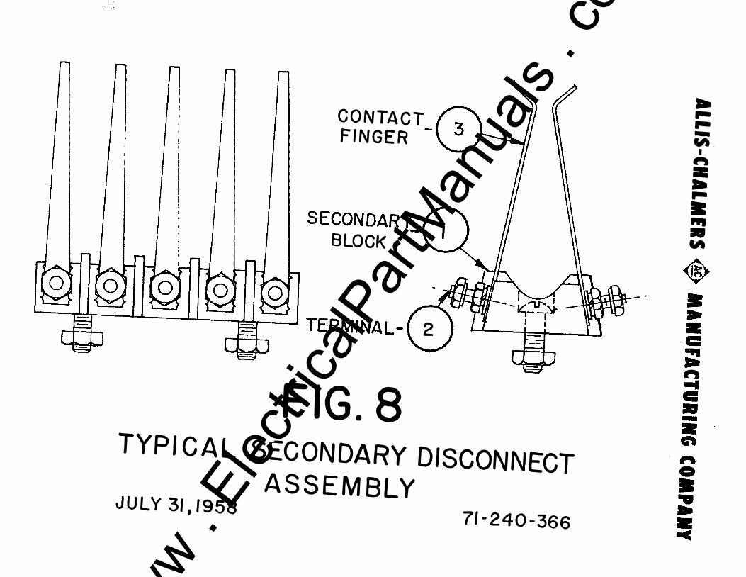
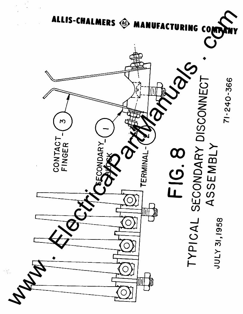
C O N TA C T F I N G E R
S ECON DAR Y_l l BLOCK
l � I I I I ,I I, I TERMI NA L - ( 2
F IG . 8 TYP I C A L SEC ON DA RY D ISCONNECT
A S S E M B LY J U LY 31 , 1 9 5 8
71 - 2 4 0 - 36 6
... .. .. -� -
1 � =... .. • ... • �
E1
-
www . El
ectric
alPar
tMan
uals
. com

www . El
ectric
alPar
tMan
uals
. com
LONG T IME DELAY ,2 1 CALBRATION LASE['
A . � f?4\_$t!ORT TIME DELAY � PICKUP SPRING
BOT T OM VIEW
INST. ARMATURE __ (23. PICKUP SPRING
BO T T OM VIEW
SHORT TIME DELAY DEVICE - SHORT TIME DELAY
ARMATURE -
DU A L SEL E CTIVE T RI P DEV I C E ( LONG 6 SHORT TIME ELEMENT S)
DUA L MA GNET IC TRIP DEVICE (LO NG T IME 6 INSTANTANEOUS ELEMEN T S)
BOT T OM V IEW SERIES INSTANTANEOUS TRIP DEVICE
(AD.A.JSTABLE 100-200% PICKUP)
METERING ELEMENT---( 12} al � TIME DELAY
DEVICE PLUNGER-- I r---:.::;:::::::;fi�� ���� ADJUSTING KNOB---{ 2
LONG T IME ARMATURE_ 1 3 CALIBRATI ON L ABEL '
FIG. I 2 SERIES OVERCURRENT TRIP DEVICE
I I LA11 TYP E BREAKERS
J U N E 6,1957 71-440-077
0
,.f''"l · : : CORE MTG.J 5 ) .7 SCREWS -,
: ( 1'1 I , : , ' I I - - - - -, I
1 I
_____ _ jj � :
0 d
... ... ... -
fA I
� II: ... ... • ... • "'
� • ... • c: ... .. � ... c: • -
•• eft � -0 • .. ... • -c
www . El
ectric
alPar
tMan
uals
. com

www . El
ectric
alPar
tMan
uals
. com
ALLIS--CHALMERS � MANUFACTURING COMPANY
.01
... �ataf r ... -oo :!.!! ADJUSTABLE
.5 .I .7 .I ,9 1
I �ON� T!M� p��f,;
2 3 4 !I I 1 I 1 10 zo 30 40 50 " 70 1090�
0 g § § g g gg .. 11'1 . .... . i-1000 100 100 700
800 000 400 300
200
100 " 10 70 10 so
40 30
20
10 • I 7 I • :::!
il: . "' 2
11-3 � � 2 t> "' I .I .I .7 .. .. ..
m :;:; ���(�-£ll.l�� ·: '�-:J=t= 1� i� f, -�- ±1::� , m�jJtl:·· ffiiffi+tm±mE:E·B�-u ··
!l !! ! ! H U� I! 8 i! !! 8 U U .... "' .. ., - ... • • !!
.I .09 .01 .07
.01
... ... . 03
.02
.01
BREAKER RATING TIMES SCALE EQUALS C URRENT I N AMPERES
FIG.I6D TIME CURRENT CURVES OF SERIES TRIP ELEMENT APRIL 7,1960 71-340-214 www . El
ectric
alPar
tMan
uals
. com

www . El
ectric
alPar
tMan
uals
. com
INSTANTANEOUS ARMATLf'E PICKUP SPRING
ll-IERMAL ARMATURE_-( 18 SPRING ·
NAME PLATE-�
3 )-BW£TALUC " ELEMENT
ADJUSTING KNOB-{ 6
��-(16:
��-{15
THERMAL MAGNETIC OVERCURRENT TRIP DEVICE
FIG. 13 JUNE 6 , 1 957 7 1 - 540-083
4)--ARMA� STOP
[---, .r�),:" r-··: / SERIES i I I / ®-- WL ! :
I _LL __ __ _ _ � � �-
I
---f_j I I) CORE M<lU'JTING .. SCREW
L--r � : I lj I
I I I
..-1
... ... ... -� -. � = ... ... • ... • �
� • ... • c: ... ... � ... c: • -•• � �-0 • .. ... • -c
www . El
ectric
alPar
tMan
uals
. com

www . El
ectric
alPar
tMan
uals
. com
ALLI.S -CHALMERS � MANUFACTURI IIG CO.MPAIY
40
30
20
1 0 9.0 8 .0 7. 0 6 .0
5.0
� 4.0 t-::> z � � LLI � �
3.0
2.0
1 . 0 . 9 .a .7 .6
.5
!4
.3
� ! \
AMBIEN T TEMPERATURE 25°C
\ \ \ \ \ 1 1 \ ' _\ \ I\ \ \ ' \
\ \
- - -
1\ \ \
"' �\
"' � ['._ ........ � i'-r--, !".. ' -r-......
� !'---� .......... -r--
t--.."-I'-- r-t-
,.--
t-
INSTANTANEOUS TRIP SET AT 800% TO 1200% NORMAL RAT I NG UNLES S OTHERWISE SPECIFI ED
CALIBRATION
- 120% SETTING - 100°/o SETTING
- 80o/o SETTING
.25 80 100 200 300 400 600 800 1 000
PERCEN T NORMAL RATING
F I G . 1 7A TYPI CAL TI M E CU RRENT C U RV E
TH E RMAL TRI P DEVI C E NOV. 4, 1955 71- 240 - 1 7 9 www . El
ectric
alPar
tMan
uals
. com

www . El
ectric
alPar
tMan
uals
. com