dc air circuit breakers moulded case circuit breakers · air circuit breakers moulded case circuit...
TRANSCRIPT

www.terasaki.co.jp
CAT REF. ’14-I73E
Air Circuit Breakers Moulded Case Circuit Breakers
&
Air Circuit Breakers Moulded Case Circuit BreakersDCDCDC
TABLE OF CONTENTS
Introduction ……………………………………………1-2
General …………………………………………………1-3
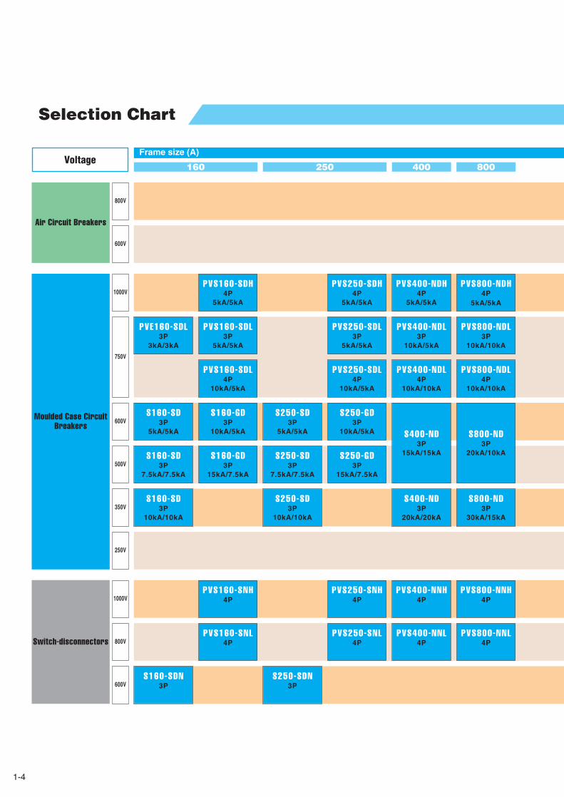
Selection Chart …………………………………………1-4
Air Circuit Breakers for DC350V-800V ………………2-2
Moulded Case Circuit Breakers for DC350V-600V …2-3
Moulded Case Circuit Breakers for DC750V-1000V…2-5
Switch-disconnectors for DC600V-1000V ……………2-7
Time/Current characteristic curves,
Ambient Compensating Curves
S160-SD, S160-GD, PVE160-SDL,
S250-SD, S250-GD 3P ……………3-2
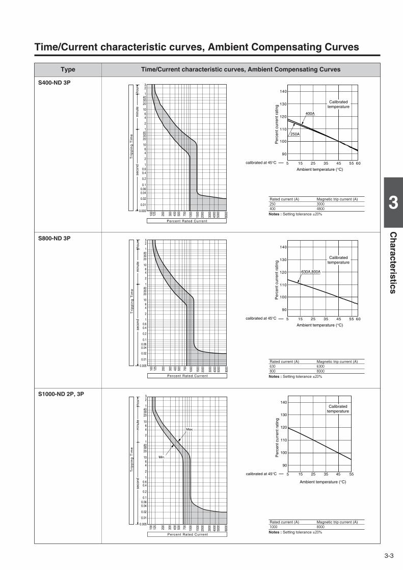
S400-ND, S800-ND 3P………………………………3-3
S1000-ND 2P, 3P ……………………………………3-3
XS1250ND, XS1600ND, XS2000ND 2P, 3P ………3-4
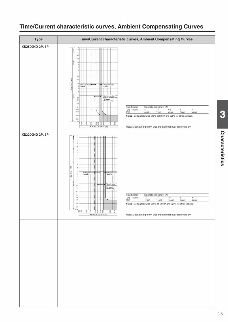
XS2500ND, XS3200ND 2P, 3P ……………………3-5
PVS160-SDL, PVS250-SDL 3P, 4P ………………3-6
PVS160-SDH, PVS250-SDH 4P……………………3-6
PVS400-NDL 3P ……………………………………3-6
PVS400-NDL, PVS400-NDH, PVS800-NDH 4P …3-7
PVS800-NDL 3P, 4P…………………………………3-7
Connection of conductors to DC circuit breakers …4-2
Insulation distance DC600V or less …………………4-7
Insulation distance DC750V-1000V
PVE160-SDL 3P ……………………………………4-8
PVS160-SDL 3P, PVS250-SDL 3P…………………4-9
PVS160-SDL 4P, PVS250-SDL 4P
PVS160-SNL 4P, PVS250-SNL 4P ……4-10
PVS160-SDH 4P, PVS250-SDH 4P
PVS160-SNH 4P, PVS250-SNH 4P ……4-11
PVS400-NDL 3P ……………………………………4-12
PVS400-NDL 4P, PVS400-NDH 4P ………………4-13
PVS400-NNL 4P, PVS400-NNH 4P ………………4-14
PVS800-NDL 3P ……………………………………4-15
PVS800-NDL 4P, PVS800-NDH 4P ………………4-16
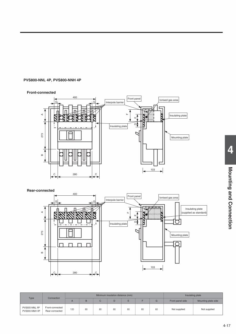
PVS800-NNL 4P, PVS800-NNH 4P ………………4-17
DC Air Circuit Breakers Outline Dimensions
AR216S, AR220S 3P…………………………………5-2
AR325S, AR332S 3P…………………………………5-4
AR325-NDH 4P ………………………………………5-6
AR440SB 3P …………………………………………5-8
AR440S 3P …………………………………………5-10
DC Moulded Case Circuit Breakers Outline Dimensions
S160-SD, S160-GD, S160-SDN,
S250-SD, S250-GD, S250-SDN 3P……5-12
S400-ND 3P…………………………………………5-13
S800-ND 3P…………………………………………5-13
S1000-ND 2P, 3P……………………………………5-14
XS1250ND 2P, 3P …………………………………5-15
XS1600ND 2P, 3P …………………………………5-16
XS2000ND 2P, 3P …………………………………5-17
XS2500ND, XS3200ND 2P, 3P ……………………5-18
PVE160-SDL 3P ……………………………………5-19
PVS160-SDL, PVS250-SDL 3P……………………5-20
PVS160-SDL, PVS250-SDL,
PVS160-SNL, PVS250-SNL 4P…………5-20
PVS160-SDH, PVS250-SDH,
PVS160-SNH, PVS250-SNH 4P ………5-21
PVS400-NDL 3P ……………………………………5-22
PVS400-NDL, PVS400-NDH 4P …………………5-23
PVS400-NNL, PVS400-NNH 4P …………………5-23
PVS800-NDL 3P ……………………………………5-24
PVS800-NDL, PVS800-NDH 4P …………………5-25
PVS800-NNL, PVS800-NNH 4P …………………5-25
5.Outline Dimensions …………………………5-1
4.Mounting and Connection…………………4-1
3.Characteristics ………………………………3-1
2.Ratings and Specifications ………………2-1
1.General ………………………………………1-1
TABLE OF CONTENTS
1-1
1
Gen
eral1Introduction ………………………………………………………………………1-2General ……………………………………………………………………………1-3Selection Chart …………………………………………………………………1-4
General
1-2
Introduction
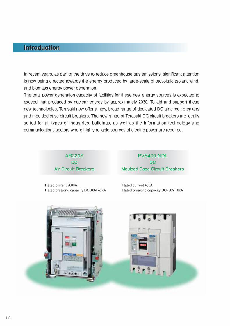
In recent years, as part of the drive to reduce greenhouse gas emissions, significant attention
is now being directed towards the energy produced by large-scale photovoltaic (solar), wind,
and biomass energy power generation.
The total power generation capacity of facilities for these new energy sources is expected to
exceed that produced by nuclear energy by approximately 2030. To aid and support these
new technologies, Terasaki now offer a new, broad range of dedicated DC air circuit breakers
and moulded case circuit breakers. The new range of Terasaki DC circuit breakers are ideally
suited for all types of industries, buildings, as well as the information technology and
communications sectors where highly reliable sources of electric power are required.
Introduction
PVS400-NDLDC
Moulded Case Circuit Breakers
AR220SDC
Air Circuit Breakers
PVS400-NDLDC
Moulded Case Circuit Breakers
AR220SDC
Air Circuit Breakers
Rated current 2000A Rated breaking capacity DC600V 40kA
Rated current 400A Rated breaking capacity DC750V 10kA
1-3
1
Gen
eral
GeneralGeneral
DC power sources for the Uninterruptible Power Supply (UPS) market
Electrical and electronic equipment used in the advanced information and communications sectors requires a
highly reliable power source. Should a power failure occur, and to assist with continuity of electrical power, it is
standard practice to install an Uninterruptable Power Supply (UPS).
A data centre is where Internet servers and other systems for data communications, such as fixed, mobile, and IP
telephones are installed. At the data centre, AC power from the main system power source is sent to the UPS,
and is temporarily converted to DC power. A storage battery is then charged with this DC power, which is re-
converted back into AC power and then sent to the information equipment.
Photovoltaic power generation
Photovoltaic (or Solar) power generation, which is attracting attention as clean energy, ranges from simple
generation of up to several kilowatts for home use, to larger systems of 100 kilowatts or greater for industrial use.
In the "School New Deal" program, one of the governmental measures during the economic crisis, were for eco-
friendly modifications which advocated the use of photovoltaic power generation at schools. One example is a
power distribution system linked to a source of photovoltaic power generation. The current produced from the
photovoltaic solar cells is sent to a power conditioner via a diode with a DC circuit breaker in a junction box and
then converted into AC, which can then be supplied to a load via a distribution board.
Building and Industrial power back-up
A UPS is typically required for critical power systems in department stores, hotels, hospitals, theaters, and office
buildings. For example, in semiconductor manufacturing plants that feature advanced automation as a part of
their production processes, UPS systems with large battery capacities are used to take measures against any
large-scale power outage affecting critical manufacturing facilities.
Rationalization of use of electric power via large-capacity storage battery
Energy from new power sources such as wind and photovoltaic power generation do not have a stable output. A
lithium ion battery and a sodium-sulfur (NAS) battery can suppress such fluctuations by load leveling. The battery
is charged at night using a lower electrical power rate at night and discharged at daytime when the electrical
power usage rate is higher, and in addition, any new electrical power generated can also be saved. For this
purpose, large-capacity storage battery systems are used at wind and photovoltaic power generation facilities.
The use of these types of systems is expected to grow across all user sectors requiring large amounts of power,
plus as an additional measure against possible power outages.
1-4
800
800V
600V
1000V
750V
600V
500V
350V
250V
1000V
800V
Selection Chart
Frame size (A)
400
600V
PVS800-NDH4P
5kA/5kA
PVS800-NDL3P
10kA/10kA
S800-ND3P
20kA/10kA
PVS400-NDH4P
5kA/5kA
PVS400-NDL3P
10kA/5kA
PVS800-NDL4P
10kA/10kA
PVS400-NDL4P
10kA/10kA
S400-ND3P
15kA/15kA
S800-ND3P
30kA/15kA
PVS800-NNH4P
PVS800-NNL4P
S400-ND3P
20kA/20kA
PVS400-NNH4P
PVS400-NNL4P
PVS250-SNL4P
Air Circuit Breakers
Moulded Case CircuitBreakers
Switch-disconnectors
Voltage160 250
S250-GD3P
10kA/5kA
PVS250-SDH4P
5kA/5kA
PVS250-SDL3P
5kA/5kA
PVS250-SDL4P
10kA/5kA
S250-GD3P
15kA/7.5kA
S160-GD3P
10kA/5kA
PVS160-SDH4P
5kA/5kA
PVS160-SDL3P
5kA/5kA
PVE160-SDL3P
3kA/3kA
PVS160-SDL4P
10kA/5kA
S160-GD3P
15kA/7.5kA
S250-SD3P
5kA/5kA
S250-SD3P
7.5kA/7.5kA
S250-SD3P
10kA/10kA
S160-SD3P
5kA/5kA
S160-SD3P
7.5kA/7.5kA
S160-SD3P
10kA/10kA
PVS160-SNL4P
PVS250-SNH4P
PVS160-SNH4P
S160-SDN3P
S250-SDN3P
1-5
1
Gen
eral
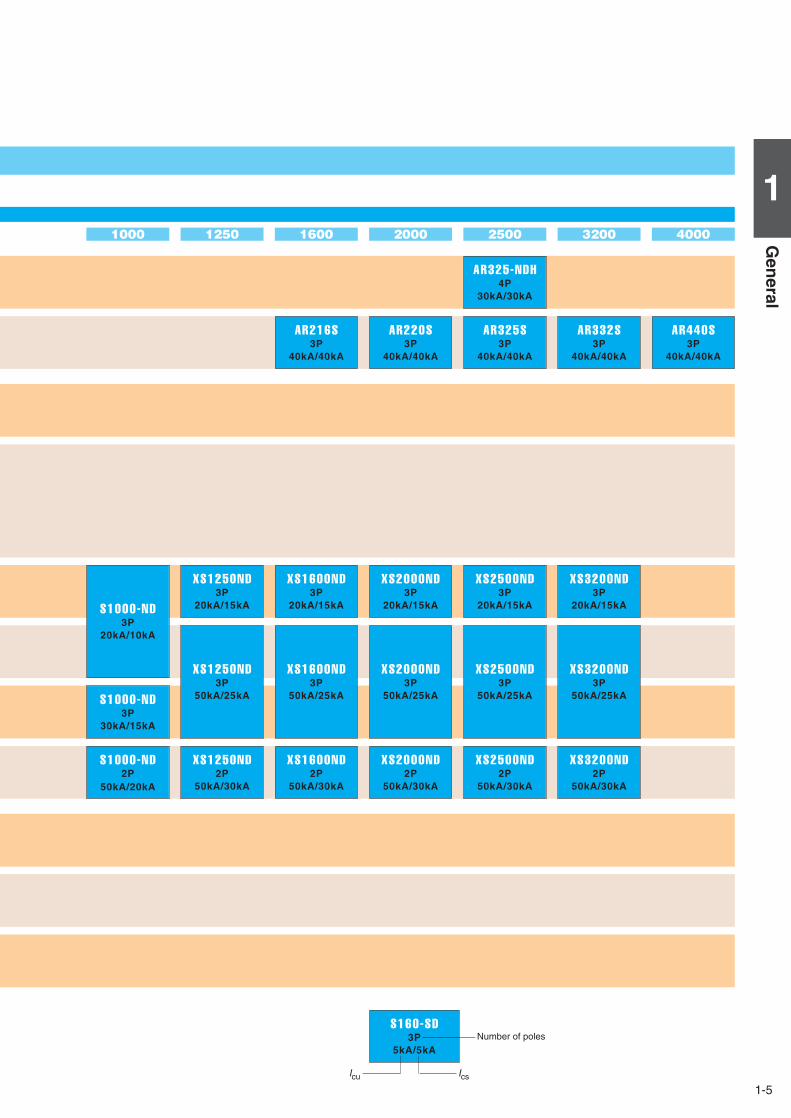
320025002000160012501000
AR325-NDH4P
30kA/30kA
AR325S3P
40kA/40kA
AR220S3P
40kA/40kA
AR216S3P
40kA/40kA
AR332S3P
40kA/40kA
4000
AR440S3P
40kA/40kA
S1000-ND3P
20kA/10kA
S1000-ND3P
30kA/15kA
S1000-ND2P
50kA/20kA
XS1250ND3P
20kA/15kA
XS1250ND3P
50kA/25kA
XS1250ND2P
50kA/30kA
XS1600ND3P
20kA/15kA
XS1600ND3P
50kA/25kA
XS1600ND2P
50kA/30kA
XS2000ND3P
20kA/15kA
XS2000ND3P
50kA/25kA
XS2000ND2P
50kA/30kA
XS2500ND3P
20kA/15kA
XS2500ND3P
50kA/25kA
XS2500ND2P
50kA/30kA
XS3200ND3P
20kA/15kA
XS3200ND3P
50kA/25kA
XS3200ND2P
50kA/30kA
S160-SD3P
5kA/5kA
IcsIcu
Number of poles

2-1
2
Ratin
gs
and
Sp
ecification
s
2Air Circuit Breakers for DC350V-800V ………………………………………2-2Moulded Case Circuit Breakers for DC350V-600V…………………………2-3Moulded Case Circuit Breakers for DC750V-1000V ………………………2-5Switch-disconnectors for DC600V-1000V …………………………………2-7
Ratings andSpecifications
2-2
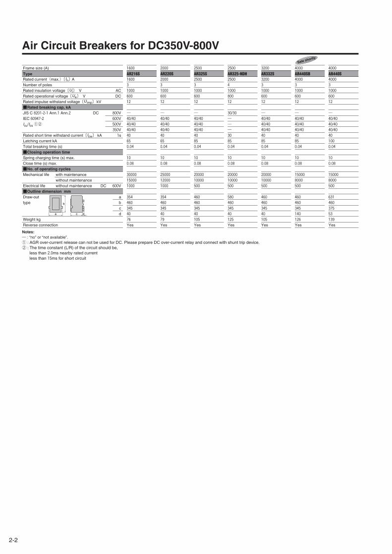
Air Circuit Breakers for DC350V-800V
Frame size (A)
Type Rated current(max.)〔In〕ANumber of polesRated insulation voltage〔Ui〕 V ACRated operational voltage〔Ue〕 V DCRated impulse withstand voltage〔U imp〕 kV■Rated breaking cap, kAJIS C 8201-2-1 Ann.1 Ann.2 DC 800VIEC 60947-2 600VIcu/Ics①② 500V
350VRated short time withstand current〔Icw〕 kA 1sLatching current kATotal breaking time (s)■Closing operation timeSpring charging time (s) max.Close time (s) max.■No. of operating cyclesMechanical life with maintenance
without maintenanceElectrical life without maintenance DC 600V■Outline dimension mmDraw-out atype b
cd
Weight kgReverse connection
1600
AR216S1600
3
1000
600
12
―40/4040/4040/4040
65
0.04
10
0.08
30000
15000
1000
354
460
345
40
76
Yes
2000
AR220S2000
3
1000
600
12
―40/4040/4040/4040
65
0.04
10
0.08
25000
12000
1000
354
460
345
40
79
Yes
2500
AR325S2500
3
1000
600
12
―40/4040/4040/4040
85
0.04
10
0.08
20000
10000
500
460
460
345
40
105
Yes
2500
AR325-NDH2500
4
1000
800
12
30/30―――30
85
0.04
10
0.08
20000
10000
500
580
460
345
40
125
Yes
3200
AR332S3200
3
1000
600
12
―40/4040/4040/4040
85
0.04
10
0.08
20000
10000
500
460
460
345
40
105
Yes
4000
AR440SB4000
3
1000
600
12
―40/4040/4040/4040
85
0.04
10
0.08
15000
8000
500
460
460
345
140
126
Yes
4000
AR440S4000
3
1000
600
12
―40/4040/4040/4040
100
0.04
10
0.08
15000
8000
500
631
460
375
53
139
Yes
Notes:― : “no” or “not available”. ① : AGR over-current release can not be used for DC. Please prepare DC over-current relay and connect with shunt trip device.② : The time constant (L/R) of the circuit should be,
less than 2.0ms nearby rated currentless than 15ms for short circuit
Sale shortly
a c d
b
2-3
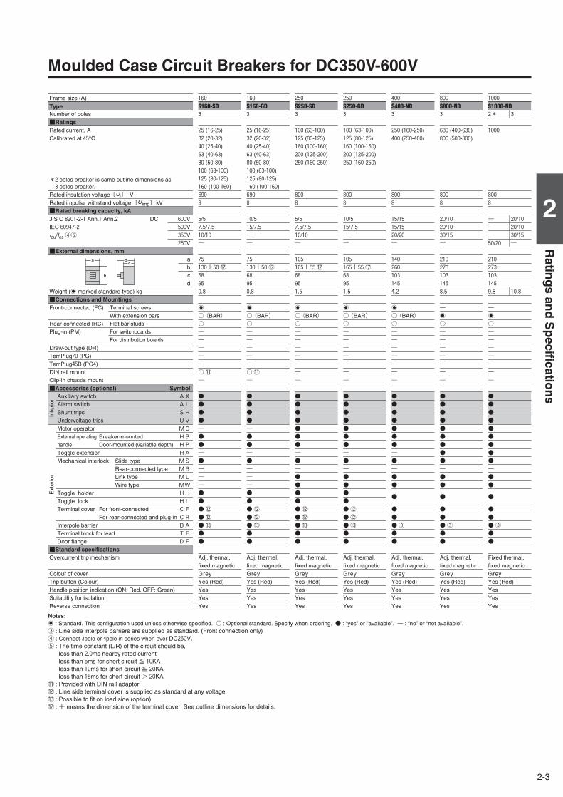
Moulded Case Circuit Breakers for DC350V-600V
2
Ratin
gs
and
Sp
ecification
s
Frame size (A)
Type Number of poles■RatingsRated current, ACalibrated at 45°C
*2 poles breaker is same outline dimensions as 3 poles breaker.
Rated insulation voltage〔Ui〕 V Rated impulse withstand voltage 〔U imp〕 kV■Rated breaking capacity, kAJIS C 8201-2-1 Ann.1 Ann.2 DC 600VIEC 60947-2 500VIcu/Ics④⑤ 350V
250V■External dimensions, mm
abcd
Weight (' marked standard type) kg■Connections and MountingsFront-connected (FC) Terminal screws
With extension barsRear-connected (RC) Flat bar studsPlug-in (PM) For switchboards
For distribution boardsDraw-out type (DR)TemPlug70 (PG)TemPlug45B (PG4)DIN rail mountClip-in chassis mount■Accessories (optional) Symbol
Auxiliary switch AXAlarm switch ALShunt trips SHUndervoltage trips UVMotor operator MCExternal operating Breaker-mounted HBhandle Door-mounted (variable depth) HPToggle extension HAMechanical interlock Slide type MS
Rear-connected type MBLink type MLWire type MW
Toggle holder HHToggle lock HLTerminal cover For front-connected CF
For rear-connected and plug-in CRInterpole barrier BATerminal block for lead TFDoor flange DF
■Standard specificationsOvercurrent trip mechanism
Colour of coverTrip button (Colour)Handle position indication (ON: Red, OFF: Green)Suitability for isolationReverse connection
160
S160-SD3
25 (16-25)32 (20-32)40 (25-40)63 (40-63)80 (50-80)100 (63-100)125 (80-125)160 (100-160)690
8
5/57.5/7.510/10―
75
130+50⑰68
95
0.8
'
○(BAR)○―――――○⑪―
●●●●―●●―●―――●●●⑫●⑫●⑬●●
Adj. thermal,fixed magneticGreyYes (Red)YesYesYes
160
S160-GD3
25 (16-25)32 (20-32)40 (25-40)63 (40-63)80 (50-80)100 (63-100)125 (80-125)160 (100-160)690
8
10/515/7.5――
75
130+50⑰68
95
0.8
'
○(BAR)○―――――○⑪―
●●●●―●●―●―――●●●⑫●⑫●⑬●●
Adj. thermal,fixed magneticGreyYes (Red)YesYesYes
250
S250-GD3
100 (63-100)125 (80-125)160 (100-160)200 (125-200)250 (160-250)
800
8
10/515/7.5――
105
165+55⑰68
95
1.5
'
○(BAR)○―――――――
●●●●●●●―●―●●●●●⑫●⑫●⑬●●
Adj. thermal,fixed magneticGreyYes (Red)YesYesYes
250
S250-SD3
100 (63-100)125 (80-125)160 (100-160)200 (125-200)250 (160-250)
800
8
5/57.5/7.510/10―
105
165+55⑰68
95
1.5
'
○(BAR)○―――――――
●●●●●●●―●―●●●●●⑫●⑫●⑬●●
Adj. thermal,fixed magneticGreyYes (Red)YesYesYes
400
S400-ND3
250 (160-250)400 (250-400)
800
8
15/1515/1520/20―
140
260
103
145
4.2
'
○(BAR)○―――――――
●●●●●●●―●―●●
●
●●●③●●
Adj. thermal,fixed magneticGreyYes (Red)YesYesYes
800
S800-ND3
630 (400-630)800 (500-800)
800
8
20/1020/1030/15―
210
273
103
145
8.5
―'
○―――――――
●●●●●●●●●―●●
●
●●●③●●
Adj. thermal,fixed magneticGreyYes (Red)YesYesYes
1000
S1000-ND2* 3
1000
800
8
― 20/10― 20/10― 30/1550/20 ―
210
273
103
145
9.8 10.8
―'
○―――――――
●●●●●●●●●―●●
●
●●●③●●
Fixed thermal,fixed magneticGreyYes (Red)YesYesYes
a
b
cd
Notes:' : Standard. This configuration used unless otherwise specified. ○ : Optional standard. Specify when ordering. ● : “yes” or “available”. ― : “no” or “not available”.③ : Line side interpole barriers are supplied as standard. (Front connection only) ④ : Connect 3pole or 4pole in series when over DC250V. ⑤ : The time constant (L/R) of the circuit should be,
less than 2.0ms nearby rated currentless than 5ms for short circuit ≦ 10KAless than 10ms for short circuit ≦ 20KAless than 15ms for short circuit > 20KA
⑪ : Provided with DIN rail adaptor.⑫ : Line side terminal cover is supplied as standard at any voltage.⑬ : Possible to fit on load side (option).⑰ : + means the dimension of the terminal cover. See outline dimensions for details.
Inte
rior
Ext
erio
r
2-4
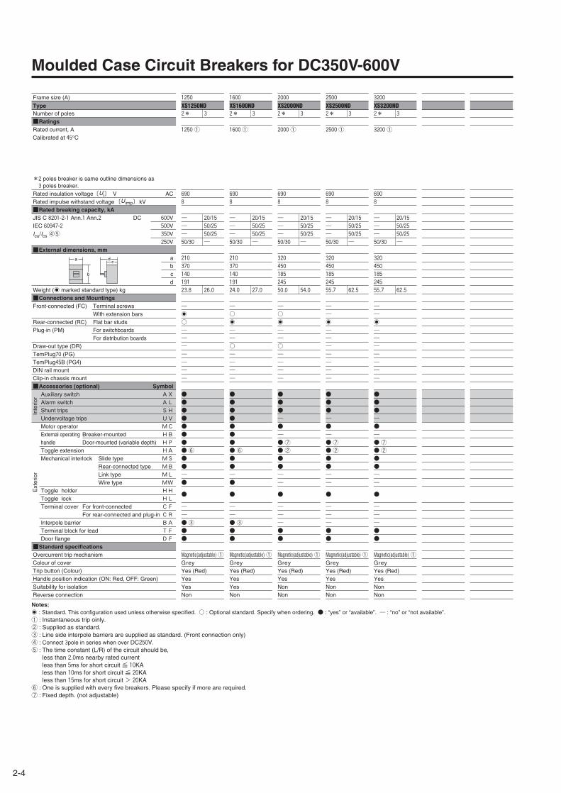
Moulded Case Circuit Breakers for DC350V-600V
Frame size (A)
Type Number of poles■RatingsRated current, ACalibrated at 45°C
*2 poles breaker is same outline dimensions as 3 poles breaker.
Rated insulation voltage〔Ui〕 V ACRated impulse withstand voltage 〔U imp〕 kV■Rated breaking capacity, kAJIS C 8201-2-1 Ann.1 Ann.2 DC 600VIEC 60947-2 500VIcu/Ics④⑤ 350V
250V■External dimensions, mm
abcd
Weight (' marked standard type) kg■Connections and MountingsFront-connected (FC) Terminal screws
With extension barsRear-connected (RC) Flat bar studsPlug-in (PM) For switchboards
For distribution boardsDraw-out type (DR)TemPlug70 (PG)TemPlug45B (PG4)DIN rail mountClip-in chassis mount■Accessories (optional) Symbol
Auxiliary switch AXAlarm switch ALShunt trips SHUndervoltage trips UVMotor operator MCExternal operating Breaker-mounted HBhandle Door-mounted (variable depth) HPToggle extension HAMechanical interlock Slide type MS
Rear-connected type MBLink type MLWire type MW
Toggle holder HHToggle lock HLTerminal cover For front-connected CF
For rear-connected and plug-in CRInterpole barrier BATerminal block for lead TFDoor flange DF
■Standard specificationsOvercurrent trip mechanismColour of coverTrip button (Colour)Handle position indication (ON: Red, OFF: Green)Suitability for isolationReverse connection
1600
XS1600ND2* 3
1600①
690
8
― 20/15― 50/25― 50/2550/30 ―
210
370
140
191
24.0 27.0
―○'
――○――――
●●●●●●●●⑥●●―●
●
――●③●●
Magnetic(adjustable)①GreyYes (Red)YesYesNon
2000
XS2000ND2* 3
2000①
690
8
― 20/15― 50/25― 50/2550/30 ―
320
450
185
245
50.0 54.0
―○'
――○――――
●●●―●―●⑦●②●●――
●
―――●●
Magnetic(adjustable)①GreyYes (Red)YesNonNon
2500
XS2500ND2* 3
2500①
690
8
― 20/15― 50/25― 50/2550/30 ―
320
450
185
245
55.7 62.5
――'
―――――――
●●●―●―●⑦●②●●――
●
―――●●
Magnetic(adjustable)①GreyYes (Red)YesNonNon
3200
XS3200ND2* 3
3200①
690
8
― 20/15― 50/25― 50/2550/30 ―
320
450
185
245
55.7 62.5
――'
―――――――
●●●―●―●⑦●②●●――
●
―――●●
Magnetic(adjustable)①GreyYes (Red)YesNonNon
1250
XS1250ND2* 3
1250①
690
8
― 20/15― 50/25― 50/2550/30 ―
210
370
140
191
23.8 26.0
―'
○―――――――
●●●●●●●●⑥●●―●
●
――●③●●
Magnetic(adjustable)①GreyYes (Red)YesYesNon
a
b
cd
Notes:' : Standard. This configuration used unless otherwise specified. ○ : Optional standard. Specify when ordering. ● : “yes” or “available”. ― : “no” or “not available”.① : Instantaneous trip oinly. ② : Supplied as standard. ③ : Line side interpole barriers are supplied as standard. (Front connection only) ④ : Connect 3pole in series when over DC250V. ⑤ : The time constant (L/R) of the circuit should be,
less than 2.0ms nearby rated currentless than 5ms for short circuit ≦ 10KAless than 10ms for short circuit ≦ 20KAless than 15ms for short circuit > 20KA
⑥ : One is supplied with every five breakers. Please specify if more are required.⑦ : Fixed depth. (not adjustable)
Inte
rior
Ext
erio
r
2-5
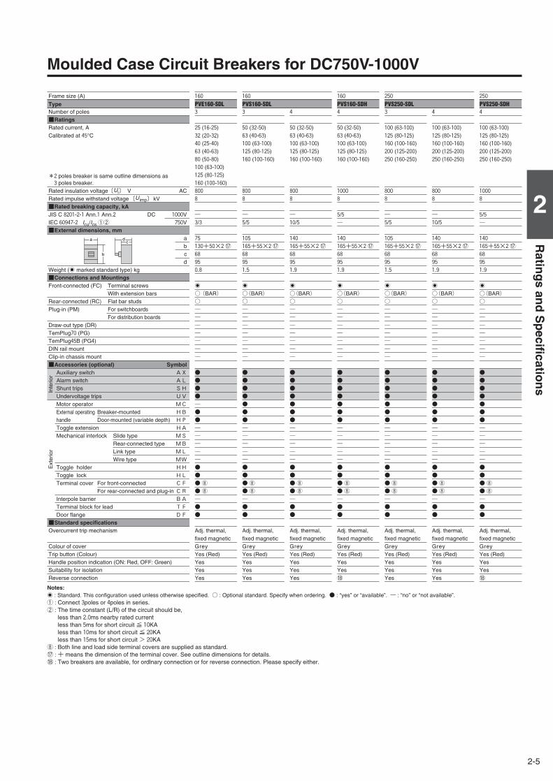
Moulded Case Circuit Breakers for DC750V-1000V
2
Ratin
gs
and
Sp
ecification
s
Frame size (A)
Type Number of poles■RatingsRated current, ACalibrated at 45°C
*2 poles breaker is same outline dimensions as 3 poles breaker.
Rated insulation voltage〔Ui〕 V ACRated impulse withstand voltage 〔U imp〕 kV■Rated breaking capacity, kAJIS C 8201-2-1 Ann.1 Ann.2 DC 1000VIEC 60947-2 Icu/Ics①② 750V■External dimensions, mm
abcd
Weight (' marked standard type) kg■Connections and MountingsFront-connected (FC) Terminal screws
With extension barsRear-connected (RC) Flat bar studsPlug-in (PM) For switchboards
For distribution boardsDraw-out type (DR)TemPlug70 (PG)TemPlug45B (PG4)DIN rail mountClip-in chassis mount■Accessories (optional) Symbol
Auxiliary switch AXAlarm switch ALShunt trips SHUndervoltage trips UVMotor operator MCExternal operating Breaker-mounted HBhandle Door-mounted (variable depth) HPToggle extension HAMechanical interlock Slide type MS
Rear-connected type MBLink type MLWire type MW
Toggle holder HHToggle lock HLTerminal cover For front-connected CF
For rear-connected and plug-in CRInterpole barrier BATerminal block for lead TFDoor flange DF
■Standard specificationsOvercurrent trip mechanism
Colour of coverTrip button (Colour)Handle position indication (ON: Red, OFF: Green)Suitability for isolationReverse connection
160
PVS160-SDL3
50 (32-50)63 (40-63)100 (63-100)125 (80-125)160 (100-160)
800
8
―5/5
105
165+55×2⑰68
95
1.5
'
○(BAR)○―――――――
●●●●●●●―――――●●●⑧●⑧―●●
Adj. thermal,fixed magneticGreyYes (Red)YesYesYes
4
50 (32-50)63 (40-63)100 (63-100)125 (80-125)160 (100-160)
800
8
―10/5
140
165+55×2⑰68
95
1.9
'
○(BAR)○―――――――
●●●●●●●―――――●●●⑧●⑧―●●
Adj. thermal,fixed magneticGreyYes (Red)YesYesYes
160
PVS160-SDH4
50 (32-50)63 (40-63)100 (63-100)125 (80-125)160 (100-160)
1000
8
5/5―
140
165+55×2⑰68
95
1.9
'
○(BAR)○―――――――
●●●●●●●―――――●●●⑧●⑧―●●
Adj. thermal,fixed magneticGreyYes (Red)YesYes⑱
250
PVS250-SDL3
100 (63-100)125 (80-125)160 (100-160)200 (125-200)250 (160-250)
800
8
―5/5
105
165+55×2⑰68
95
1.5
'
○(BAR)○―――――――
●●●●●●●―――――●●●⑧●⑧―●●
Adj. thermal,fixed magneticGreyYes (Red)YesYesYes
4
100 (63-100)125 (80-125)160 (100-160)200 (125-200)250 (160-250)
800
8
―10/5
140
165+55×2⑰68
95
1.9
'
○(BAR)○―――――――
●●●●●●●―――――●●●⑧●⑧―●●
Adj. thermal,fixed magneticGreyYes (Red)YesYesYes
250
PVS250-SDH4
100 (63-100)125 (80-125)160 (100-160)200 (125-200)250 (160-250)
1000
8
5/5―
140
165+55×2⑰68
95
1.9
'
○(BAR)○―――――――
●●●●●●●―――――●●●⑧●⑧―●●
Adj. thermal,fixed magneticGreyYes (Red)YesYes⑱
160
PVE160-SDL3
25 (16-25)32 (20-32)40 (25-40)63 (40-63)80 (50-80)100 (63-100)125 (80-125)160 (100-160)800
8
―3/3
75
130+50×2⑰68
95
0.8
'
○(BAR)○―――――――
●●●●―●●―――――●●●⑧●⑧―●●
Adj. thermal,fixed magneticGreyYes (Red)YesYesYes
a
b
cd
Notes:' : Standard. This configuration used unless otherwise specified. ○ : Optional standard. Specify when ordering. ● : “yes” or “available”. ― : “no” or “not available”.① : Connect 3poles or 4poles in series. ② : The time constant (L/R) of the circuit should be,
less than 2.0ms nearby rated currentless than 5ms for short circuit ≦ 10KAless than 10ms for short circuit ≦ 20KAless than 15ms for short circuit > 20KA
⑧ : Both line and load side terminal covers are supplied as standard.⑰ : + means the dimension of the terminal cover. See outline dimensions for details.⑱ : Two breakers are available, for ordlnary connection or for reverse connection. Please specify either.
Inte
rior
Ext
erio
r
2-6
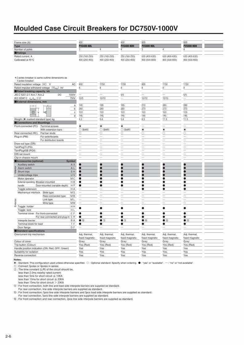
Moulded Case Circuit Breakers for DC750V-1000V
Frame size (A)
Type Number of poles■RatingsRated current, ACalibrated at 45°C
*2 poles breaker is same outline dimensions as 3 poles breaker.
Rated insulation voltage〔Ui〕 V ACRated impulse withstand voltage 〔U imp〕 kV■Rated breaking capacity, kAJIS C 8201-2-1 Ann.1 Ann.2 DC 1000VIEC 60947-2 Icu/Ics①② 750V■External dimensions, mm
abcd
Weight (' marked standard type) kg■Connections and MountingsFront-connected (FC) Terminal screws
With extension barsRear-connected (RC) Flat bar studsPlug-in (PM) For switchboards
For distribution boardsDraw-out type (DR)TemPlug70 (PG)TemPlug45B (PG4)DIN rail mountClip-in chassis mount■Accessories (optional) Symbol
Auxiliary switch AXAlarm switch ALShunt trips SHUndervoltage trips UVMotor operator MCExternal operating Breaker-mounted HBhandle Door-mounted (variable depth) HPToggle extension HAMechanical interlock Slide type MS
Rear-connected type MBLink type MLWire type MW
Toggle holder HHToggle lock HLTerminal cover For front-connected CF
For rear-connected and plug-in CRInterpole barrier BATerminal block for lead TFDoor flange DF
■Standard specificationsOvercurrent trip mechanism
Colour of coverTrip button (Colour)Handle position indication (ON: Red, OFF: Green)Suitability for isolationReverse connection
400
PVS400-NDL3
250 (160-250)400 (250-400)
800
8
―10/5
140
260
103
145
4.2
'
○(BAR)○―――――――
●●●●●●●―――――
●
●●●⑯●―
Adj. thermal,fixed magneticGreyYes (Red)YesYesYes
4
250 (160-250)400 (250-400)
1150
8
―10/10
185
260
103
145
5.6
'
○(BAR)○―――――――
●●●●●●●―――――
●
●●●⑨●―
Adj. thermal,fixed magneticGreyYes (Red)YesYesYes
400
PVS400-NDH4
250 (160-250)400 (250-400)
1150
8
5/5―
185
260
103
145
5.6
'
○(BAR)○―――――――
●●●●●●●―――――
●
●●●⑨●―
Adj. thermal,fixed magneticGreyYes (Red)YesYesYes
800
PVS800-NDL3
630 (400-630)800 (500-800)
800
8
―10/10
210
273
103
145
8.5
―'
○―――――――
●●●●●●●●――――
●
●●●⑯●―
Adj. thermal,fixed magneticGreyYes (Red)YesYesYes
4
630 (400-630)800 (500-800)
1150
8
―10/10
280
273
103
145
11.5
―'
○―――――――
●●●●●●●●――――
●
●●●⑩●―
Adj. thermal,fixed magneticGreyYes (Red)YesYesYes
800
PVS800-NDH4
630 (400-630)800 (500-800)
1150
8
5/5―
280
273
103
145
11.5
―'
○―――――――
●●●●●●●●――――
●
●●●⑩●―
Adj. thermal,fixed magneticGreyYes (Red)YesYesYes
a
b
cd
Notes:' : Standard. This configuration used unless otherwise specified. ○ : Optional standard. Specify when ordering. ● : “yes” or “available”. ― : “no” or “not available”.① : Connect 3poles or 4poles in series. ② : The time constant (L/R) of the circuit should be,
less than 2.0ms nearby rated currentless than 5ms for short circuit ≦ 10KAless than 10ms for short circuit ≦ 20KAless than 15ms for short circuit > 20KA
⑨ : For front connection, both line and load side interpole barriers are supplied as standard.For rear connection, line side interpole barriers are supplied as standard.
⑩ : For front connection, 5pcs line side interpole barriers and 3pcs load side interpole barriers are supplied as standard.For rear connection, 5pcs line side interpole barriers are supplied as standard.
⑯ : For front connection and rear connection, 2pcs line side interpole barriers are supplied as standard.
Inte
rior
Ext
erio
r
2-7
2
Ratin
gs
and
Sp
ecification
s
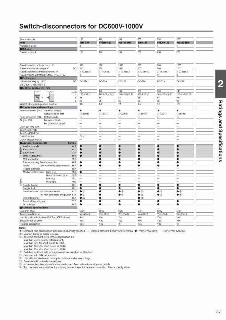
Switch-disconnectors for DC600V-1000V
Frame size (A)
Type Number of poles■RatingsRated current, A
Rated insulation voltage〔Ui〕 V Rated operational voltage V DCRated short time withstand current, kARated impulse withstand voltage 〔U imp〕 kV■PerformanceUtilization category ①② DCJIS C 8201-3 IEC 60947-3■External dimensions, mm
abcd
Weight (' marked standard type) kg■Connections and MountingsFront-connected (FC) Terminal screws
With extension barsRear-connected (RC) Flat bar studsPlug-in (PM) For switchboards
For distribution boardsDraw-out type (DR)TemPlug70 (PG)TemPlug45B (PG4)DIN rail mountClip-in chassis mount■Accessories (optional) Symbol
Auxiliary switch AXAlarm switch ALShunt trips SHUndervoltage trips UVMotor operator MCExternal operating Breaker-mounted HBhandle Door-mounted (variable depth) HPToggle extension HAMechanical interlock Slide type MS
Rear-connected type MBLink type MLWire type MW
Toggle holder HHToggle lock HLTerminal cover For front-connected CF
For rear-connected and plug-in CRInterpole barrier BATerminal block for lead TFDoor flange DF
■Standard specificationsColour of coverTrip button (Colour)Handle position indication (ON: Red, OFF: Green)Suitability for isolationReverse connection
250
S250-SDN3
250
800
600
3(0.3sec.)8
DC-22A
105
165+55⑰68
95
1.5
'
○(BAR)○―――――――
●●●●●●●―――――●●●⑫●⑫●⑬●●
GreyYes (Red)YesYesYes
160
PVS160-SNL4
160
800
800
3(0.3sec.)8
DC-22A
140
165+55×2⑰68
95
1.9
'
○(BAR)○―――――――
●●●●●●●―――――●●●●●●●
GreyYes (Red)YesYesYes
160
S160-SDN3
160
690
600
2(0.3sec.)8
DC-22A
75
130+50⑰68
95
0.8
'
○(BAR)○―――――○⑪―
●●●●―●●―●―――●●●⑫●⑫●⑬●●
GreyYes (Red)YesYesYes
160
PVS160-SNH4
160
1000
1000
3(0.3sec.)8
DC-22A
140
165+55×2⑰68
95
1.9
'
○(BAR)○―――――――
●●●●●●●―――――●●●⑧●⑧―●●
GreyYes (Red)YesYes⑱
250
PVS250-SNL4
250
800
800
3(0.3sec.)8
DC-22A
140
165+55×2⑰68
95
1.9
'
○(BAR)○―――――――
●●●●●●●―――――●●●⑧●⑧―●●
GreyYes (Red)YesYesYes
250
PVS250-SNH4
250
1000
1000
3(0.3sec.)8
DC-22A
140
165+55×2⑰68
95
1.9
'
○(BAR)○―――――――
●●●●●●●―――――●●●⑧●⑧―●●
GreyYes (Red)YesYes⑱
a
b
cd
Notes:' : Standard. This configuration used unless otherwise specified. ○ : Optional standard. Specify when ordering. ● : “yes” or “available”. ― : “no” or “not available”.① : Connect 3poles or 4poles in series. ② : The time constant (L/R) of the circuit should be,
less than 2.0ms nearby rated currentless than 5ms for short circuit ≦ 10KAless than 10ms for short circuit ≦ 20KAless than 15ms for short circuit > 20KA
⑧ : Both line and load side terminal covers are supplied as standard.⑪ : Provided with DIN rail adaptor.⑫ : Line side terminal cover is supplied as standard at any voltage.⑬ : Possible to fit on load side (option).⑰ : + means the dimension of the terminal cover. See outline dimensions for details.⑱ : Two breakers are available, for ordlnary connection or for reverse connection. Please specify either.
Inte
rior
Ext
erio
r
2-8
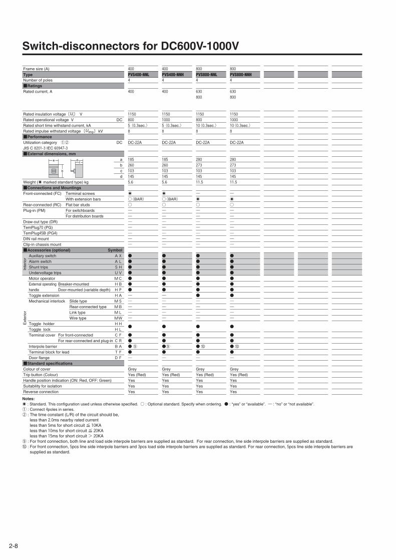
Switch-disconnectors for DC600V-1000V
Frame size (A)
Type Number of poles■RatingsRated current, A
Rated insulation voltage〔Ui〕 V Rated operational voltage V DCRated short time withstand current, kARated impulse withstand voltage 〔U imp〕 kV■PerformanceUtilization category ①② DCJIS C 8201-3 IEC 60947-3■External dimensions, mm
abcd
Weight (' marked standard type) kg■Connections and MountingsFront-connected (FC) Terminal screws
With extension barsRear-connected (RC) Flat bar studsPlug-in (PM) For switchboards
For distribution boardsDraw-out type (DR)TemPlug70 (PG)TemPlug45B (PG4)DIN rail mountClip-in chassis mount■Accessories (optional) Symbol
Auxiliary switch AXAlarm switch ALShunt trips SHUndervoltage trips UVMotor operator MCExternal operating Breaker-mounted HBhandle Door-mounted (variable depth) HPToggle extension HAMechanical interlock Slide type MS
Rear-connected type MBLink type MLWire type MW
Toggle holder HHToggle lock HLTerminal cover For front-connected CF
For rear-connected and plug-in CRInterpole barrier BATerminal block for lead TFDoor flange DF
■Standard specificationsColour of coverTrip button (Colour)Handle position indication (ON: Red, OFF: Green)Suitability for isolationReverse connection
800
PVS800-NNH4
630
800
1150
1000
10(0.3sec.)8
DC-22A
280
273
103
145
11.5
―'
○―――――――
●●●●●●●●――――
●
●●●⑩●―
GreyYes (Red)YesYesYes
400
PVS400-NNH4
400
1150
1000
5(0.3sec.)8
DC-22A
185
260
103
145
5.6
'
○(BAR)○―――――――
●●●●●●●―――――
●
●●●⑨●―
GreyYes (Red)YesYesYes
400
PVS400-NNL4
400
1150
800
5(0.3sec.)8
DC-22A
185
260
103
145
5.6
'
○(BAR)○―――――――
●●●●●●●―――――
●
●●●⑨●―
GreyYes (Red)YesYesYes
800
PVS800-NNL4
630
800
1150
800
10(0.3sec.)8
DC-22A
280
273
103
145
11.5
―'
○―――――――
●●●●●●●●――――
●
●●●⑩●―
GreyYes (Red)YesYesYes
a
b
cd
Notes:' : Standard. This configuration used unless otherwise specified. ○ : Optional standard. Specify when ordering. ● : “yes” or “available”. ― : “no” or “not available”.① : Connect 4poles in series. ② : The time constant (L/R) of the circuit should be,
less than 2.0ms nearby rated currentless than 5ms for short circuit ≦ 10KAless than 10ms for short circuit ≦ 20KAless than 15ms for short circuit > 20KA
⑨ : For front connection, both line and load side interpole barriers are supplied as standard. For rear connection, line side interpole barriers are supplied as standard. ⑩ : For front connection, 5pcs line side interpole barriers and 3pcs load side interpole barriers are supplied as standard. For rear connection, 5pcs line side interpole barriers are
supplied as standard.
Inte
rior
Ext
erio
r
3-1
3
Ch
aracteristics
3Time/Current characteristic curves, Ambient Compensating Curves
S160-SD, S160-GD, PVE160-SDL, S250-SD, S250-GD 3P……………3-2S400-ND, S800-ND 3P ……………………………………………………3-3S1000-ND 2P, 3P ……………………………………………………………3-3XS1250ND, XS1600ND, XS2000ND 2P, 3P ……………………………3-4XS2500ND, XS3200ND 2P, 3P ……………………………………………3-5PVS160-SDL, PVS250-SDL 3P, 4P ………………………………………3-6PVS160-SDH, PVS250-SDH 4P …………………………………………3-6PVS400-NDL 3P ……………………………………………………………3-6PVS400-NDL, PVS400-NDH, PVS800-NDH 4P…………………………3-7PVS800-NDL 3P, 4P ………………………………………………………3-7
Characteristics
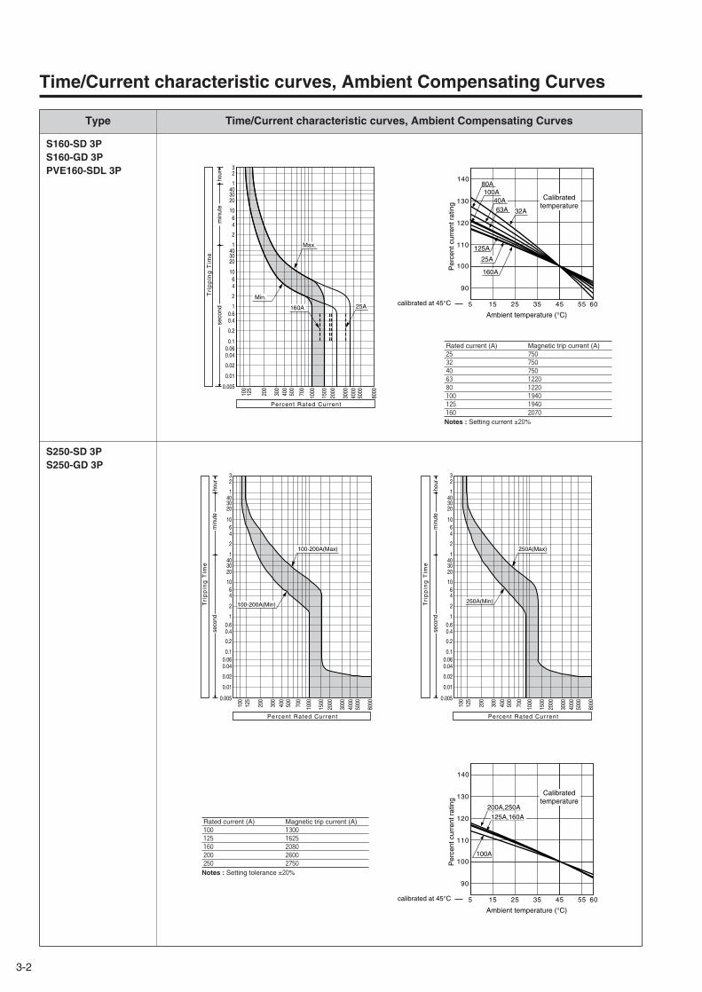
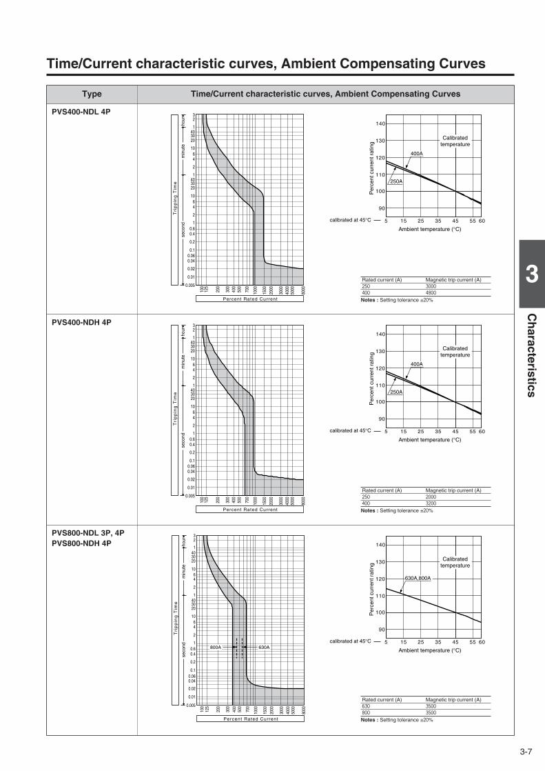
Type Time/Current characteristic curves, Ambient Compensating Curves
S160-SD 3PS160-GD 3PPVE160-SDL 3P
S250-SD 3PS250-GD 3P
3-2
seco
ndm
inut
eho
ur
100
125
200
300
400
500
700
1000
1500
2000
3000
4000
5000
8000
0.005
0.01
0.02
0.040.06
0.1
0.2
0.40.6
1
2
46
10
203040
1
2
46
10
203040
1
23
Max.
25A
Min.
160A
Tri
pp
ing
Tim
e
Percent Rated Current
140
130
120
110
100
90
5 15 25 35 45 55 60
100A
63A40A
80A
32A
25A
160A
125A
Calibratedtemperature
Ambient temperature (°C)
Per
cent
cur
rent
rat
ing
calibrated at 45°C
100
125
200
300
400
500
700
1000
1500
2000
3000
4000
5000
8000
0.005
0.01
0.02
0.040.060.1
0.2
0.40.6
1
2
46
10
203040
1
2
46
10
203040
1
23
hour
min
ute
seco
nd
Percent Rated Current
Tri
pp
ing
Tim
e
100-200A(Max)
100-200A(Min)
Time/Current characteristic curves, Ambient Compensating Curves
Rated current (A) Magnetic trip current (A)25 750
32 750
40 750
63 1220
80 1220
100 1940
125 1940
160 2070
Notes : Setting current ±20%
100
125
200
300
400
500
700
1000
1500
2000
3000
4000
5000
8000
0.005
0.01
0.02
0.040.060.1
0.2
0.40.6
1
2
46
10
203040
1
2
46
10
203040
1
23
hour
min
ute
seco
nd
Percent Rated Current
Tri
pp
ing
Tim
e
250A(Max)
250A(Min)
140
130
120
110
100
90
5 15 25 35 45 55
100A
200A,250A
125A,160A
60
Calibratedtemperature
Ambient temperature (°C)
Per
cent
cur
rent
rat
ing
calibrated at 45°C
Rated current (A) Magnetic trip current (A)100 1300
125 1625
160 2080
200 2600
250 2750
Notes : Setting tolerance ±20%
Type Time/Current characteristic curves, Ambient Compensating Curves
S400-ND 3P
S1000-ND 2P, 3P
S800-ND 3P
3-3
3
Ch
aracteristics
seco
ndm
inut
eho
ur
100
125
200
300
400
500
700
1000
1500
2000
3000
4000
5000
8000
0.005
0.01
0.02
0.040.060.1
0.2
0.40.6
1
2
46
10
2030401
2
46
10
2030401
23
Tri
pp
ing
Tim
e
Percent Rated Current
5 15 25 35 45 55 60
400A
250A
140
130
120
110
100
90
Calibratedtemperature
Ambient temperature (°C)
Per
cent
cur
rent
rat
ing
calibrated at 45°C
Time/Current characteristic curves, Ambient Compensating Curves
Rated current (A) Magnetic trip current (A)250 3000
400 4800
Notes : Setting tolerance ±20%
hour
min
ute
seco
nd
100
125
200
300
400
500
700
1000
1500
2000
3000
4000
5000
8000
0.005
0.01
0.02
0.040.060.1
0.2
0.40.6
1
2
46
10
2030401
2
46
10
2030401
23
Tri
pp
ing
Tim
e
Percent Rated Current
Max.
Min.
seco
ndm
inut
eho
ur
100
125
200
300
400
500
700
1000
1500
2000
3000
4000
5000
8000
0.005
0.01
0.02
0.040.060.1
0.2
0.40.6
1
2
46
10
2030401
2
46
10
2030401
23
Tri
pp
ing
Tim
e
Percent Rated Current
5 15 25 35 45 55 60
630A,800A
140
130
120
110
100
90
Calibratedtemperature
Ambient temperature (°C)
Per
cent
cur
rent
rat
ing
calibrated at 45°C
140
130
120
110
100
90
5 15 25 35 45 55
Calibratedtemperature
Ambient temperature (°C)
Per
cent
cur
rent
rat
ing
calibrated at 45°C
Rated current (A) Magnetic trip current (A)630 6300
800 8000
Notes : Setting tolerance ±20%
Rated current (A) Magnetic trip current (A)1000 8000
Notes : Setting tolerance ±20%
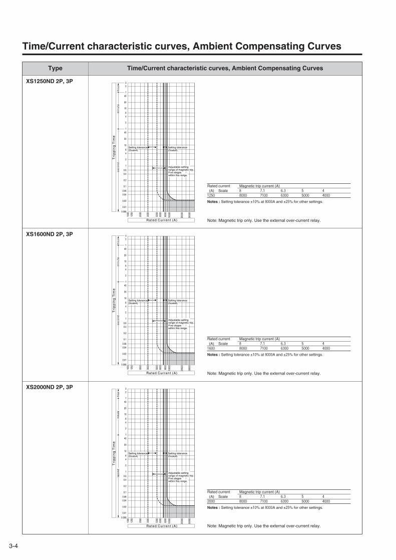
Type Time/Current characteristic curves, Ambient Compensating Curves
XS1250ND 2P, 3P
XS1600ND 2P, 3P
XS2000ND 2P, 3P
3-4
se
co
nd
min
ute
h
ou
r
0.006
0.01
0.02
0.04
0.06
0.1
0.2
0.4
0.6
1
2
4
6
10
20
40
1
2
4
6
10
20
40
1
23
1000
2000
1250
3000
5000
6000
8000
1000
0
2000
0
3000
0
Ra ted Current (A)
Tri
pp
ing
Tim
e
Setting tolerance(Scale4)
Setting tolerance(Scale8)
Adjustable setting range of magnetic trip. Five stageswithin this range.
Note: Magnetic trip only. Use the external over-current relay.
se
co
nd
min
ute
h
ou
r
0.006
0.01
0.02
0.04
0.06
0.1
0.2
0.4
0.6
1
2
4
6
10
20
40
1
2
4
6
10
20
40
1
23
1000
2000
1250
3000
5000
6000
8000
1000
0
2000
0
3000
0
Ra ted Current (A)
Tri
pp
ing
Tim
e
Setting tolerance(Scale4)
Setting tolerance(Scale8)
Adjustable setting range of magnetic trip. Five stageswithin this range.
seco
ndm
inut
e ho
ur
0.006
0.01
0.02
0.04
0.06
0.1
0.2
0.4
0.6
1
2
4
6
10
20
40
1
2
4
6
10
20
40
1
23
1000
2000
1250
3000
5000
6000
8000
1000
0
2000
0
3000
0
Setting tolerance(Scale4)
Setting tolerance(Scale8)
Adjustable setting range of magnetic trip. Five stageswithin this range.
Rated Current (A)
Tri
pp
ing
Tim
e
Note: Magnetic trip only. Use the external over-current relay.
Time/Current characteristic curves, Ambient Compensating Curves
Rated current Magnetic trip current (A)(A) Scale 8 7.1 6.3 5 4
1250 8000 7100 6300 5000 4000
Notes : Setting tolerance ±10% at 8000A and ±25% for other settings.
Rated current Magnetic trip current (A)(A) Scale 8 7.1 6.3 5 4
1600 8000 7100 6300 5000 4000
Notes : Setting tolerance ±10% at 8000A and ±25% for other settings.
Rated current Magnetic trip current (A)(A) Scale 8 7.1 6.3 5 4
2000 8000 7100 6300 5000 4000
Notes : Setting tolerance ±10% at 8000A and ±25% for other settings.
Note: Magnetic trip only. Use the external over-current relay.
3-5
3
Ch
aracteristics
Type Time/Current characteristic curves, Ambient Compensating Curves
XS2500ND 2P, 3P
XS3200ND 2P, 3P
Note: Magnetic trip only. Use the external over-current relay.
seco
ndm
inut
e ho
ur
0.006
0.01
0.02
0.04
0.06
0.1
0.2
0.4
0.6
1
2
4
6
10
20
40
1
2
4
6
10
20
40
1
23
1000
2000
1250
3000
5000
6000
8000
1000
0
2000
0
3000
0
Setting tolerance(Scale4)
Setting tolerance(Scale8)
Adjustable setting range of magnetic trip. Five stageswithin this range.
Rated Current (A)
Tri
pp
ing
Tim
e
Time/Current characteristic curves, Ambient Compensating Curves
Rated current Magnetic trip current (A)(A) Scale 8 7.1 6.3 5 4
2500 8000 7100 6300 5000 4000
Notes : Setting tolerance ±10% at 8000A and ±25% for other settings.
Tri
pp
ing
Tim
e
Ra ted Current (A)
seco
ndm
inut
eho
ur
0.006
0.01
0.02
0.04
0.06
0.1
0.2
0.4
0.6
1
2
4
6
10
20
40
1
2
4
6
10
20
40
1
23
1000
2000
1250
3000
5000
6000
8000
1000
0
2000
0
3000
0
Setting tolerance(Scale6)
Setting tolerance(Scale12)
Adjustable setting range of magnetic trip. Five stageswithin this range.
Note: Magnetic trip only. Use the external over-current relay.
Rated current Magnetic trip current (A)(A) Scale 12 11 10 8 6
3200 12000 11000 10000 8000 6000
Notes : Setting tolerance ±10% at 12000A and ±25% for other settings.
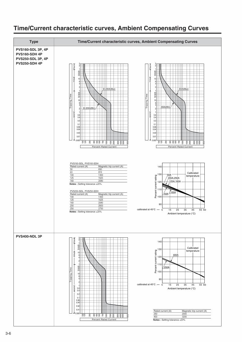
Type Time/Current characteristic curves, Ambient Compensating Curves
PVS160-SDL 3P, 4PPVS160-SDH 4PPVS250-SDL 3P, 4PPVS250-SDH 4P
PVS400-NDL 3P
3-6
Time/Current characteristic curves, Ambient Compensating Curves
seco
ndm
inut
eho
ur
100
125
200
300
400
500
700
1000
1500
2000
3000
4000
5000
8000
0.005
0.01
0.02
0.040.060.1
0.2
0.40.6
1
2
46
10
2030401
2
46
10
2030401
23
Tri
pp
ing
Tim
e
Percent Rated Current
5 15 25 35 45 55 60
400A
250A
140
130
120
110
100
90
Calibratedtemperature
Ambient temperature (°C)
Per
cent
cur
rent
rat
ing
calibrated at 45°C
Rated current (A) Magnetic trip current (A)250 2000
400 3200
Notes : Setting tolerance ±20%
100
125
200
300
400
500
700
1000
1500
2000
3000
4000
5000
8000
0.005
0.01
0.02
0.040.060.1
0.2
0.40.6
1
2
46
10
203040
1
2
46
10
203040
1
23
hour
min
ute
seco
nd
Percent Rated Current
Tri
pp
ing
Tim
e
50-200A(Max)
50-200A(Min)
100
125
200
300
400
500
700
1000
1500
2000
3000
4000
5000
8000
0.005
0.01
0.02
0.040.060.1
0.2
0.40.6
1
2
46
10
203040
1
2
46
10
203040
1
23
hour
min
ute
seco
nd
Percent Rated CurrentT
rip
pin
g T
ime
250A(Max)
250A(Min)
140
130
120
110
100
90
5 15 25 35 45 55
200A,250A
125A,160A
50A
100A 63A
60
Calibratedtemperature
Ambient temperature (°C)
Per
cent
cur
rent
rat
ing
calibrated at 45°C
PVS160-SDL, PVS160-SDHRated current (A) Magnetic trip current (A)50 650
63 819
100 1300
125 1625
160 2080
Notes : Setting tolerance ±20%
PVS250-SDL, PVS250-SDHRated current (A) Magnetic trip current (A)100 1300
125 1625
160 2080
200 2600
250 2750
Notes : Setting tolerance ±20%
3-7
3
Ch
aracteristics
Type Time/Current characteristic curves, Ambient Compensating Curves
PVS400-NDL 4P
PVS400-NDH 4P
PVS800-NDL 3P, 4PPVS800-NDH 4P
Time/Current characteristic curves, Ambient Compensating Curves
seco
ndm
inut
eho
ur
100
125
200
300
400
500
700
1000
1500
2000
3000
4000
5000
8000
0.005
0.01
0.02
0.040.060.1
0.2
0.40.6
1
2
46
10
2030401
2
46
10
2030401
23
630A800A
Tri
pp
ing
Tim
e
Percent Rated Current
5 15 25 35 45 55 60
630A,800A
140
130
120
110
100
90
Calibratedtemperature
Ambient temperature (°C)
Per
cent
cur
rent
rat
ing
calibrated at 45°C
seco
ndm
inut
eho
ur
100
125
200
300
400
500
700
1000
1500
2000
3000
4000
5000
8000
0.005
0.01
0.02
0.040.060.1
0.2
0.40.6
1
2
46
10
2030401
2
46
10
2030401
23
Tri
pp
ing
Tim
e
Percent Rated Current
5 15 25 35 45 55 60
400A
250A
140
130
120
110
100
90
Calibratedtemperature
Ambient temperature (°C)
Per
cent
cur
rent
rat
ing
calibrated at 45°C
Rated current (A) Magnetic trip current (A)250 2000
400 3200
Notes : Setting tolerance ±20%
Rated current (A) Magnetic trip current (A)630 3500
800 3500
Notes : Setting tolerance ±20%
seco
ndm
inut
eho
ur
100
125
200
300
400
500
700
1000
1500
2000
3000
4000
5000
8000
0.005
0.01
0.02
0.040.060.1
0.2
0.40.6
1
2
46
10
2030401
2
46
10
2030401
23
Tri
pp
ing
Tim
e
Percent Rated Current
5 15 25 35 45 55 60
400A
250A
140
130
120
110
100
90
Calibratedtemperature
Ambient temperature (°C)
Per
cent
cur
rent
rat
ing
calibrated at 45°C
Rated current (A) Magnetic trip current (A)250 3000
400 4800
Notes : Setting tolerance ±20%

4-1
4
Mo
un
ting
and
Co
nn
ection
4Connection of conductors to DC circuit breakers…………………………4-2Insulation distance DC600V or less …………………………………………4-7Insulation distance DC750V-1000V
PVE160-SDL 3P ………………………………………………………………4-8PVS160-SDL 3P, PVS250-SDL 3P …………………………………………4-9PVS160-SDL 4P, PVS250-SDL 4P,
PVS160-SNL 4P, PVS250-SNL 4P………………………………4-10PVS160-SDH 4P, PVS250-SDH 4P,
PVS160-SNH 4P, PVS250-SNH 4P ……………………………4-11PVS400-NDL 3P………………………………………………………………4-12PVS400-NDL 4P, PVS400-NDH 4P ………………………………………4-13PVS400-NNL 4P, PVS400-NNH 4P ………………………………………4-14PVS800-NDL 3P………………………………………………………………4-15PVS800-NDL 4P, PVS800-NDH 4P ………………………………………4-16PVS800-NNL 4P, PVS800-NNH 4P ………………………………………4-17
Mounting andConnection
4-2
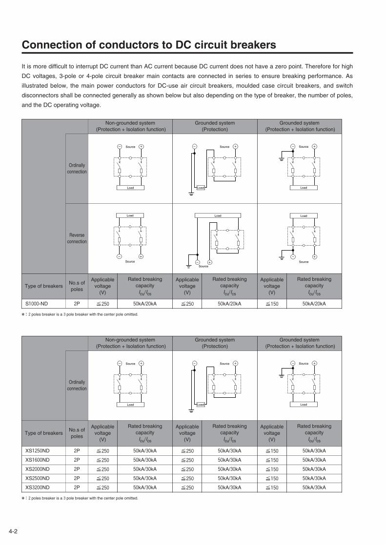
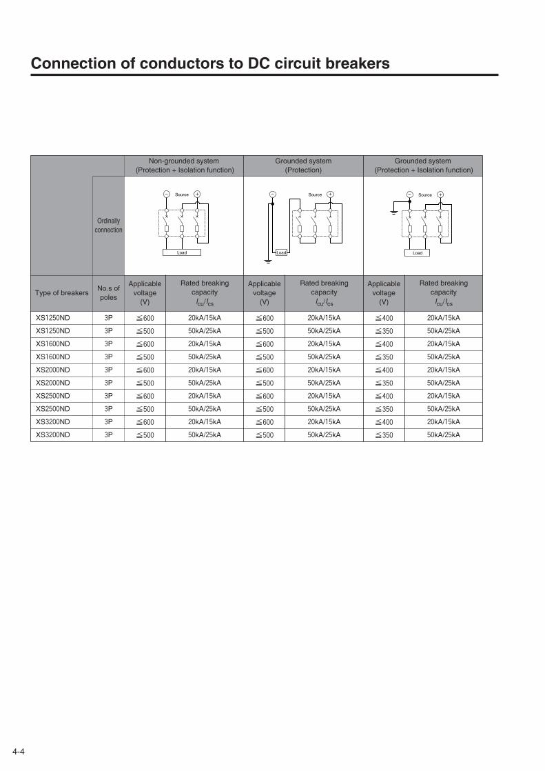
Connection of conductors to DC circuit breakers
It is more difficult to interrupt DC current than AC current because DC current does not have a zero point. Therefore for high
DC voltages, 3-pole or 4-pole circuit breaker main contacts are connected in series to ensure breaking performance. As
illustrated below, the main power conductors for DC-use air circuit breakers, moulded case circuit breakers, and switch
disconnectors shall be connected generally as shown below but also depending on the type of breaker, the number of poles,
and the DC operating voltage.
Type of breakersNo.s ofpoles
Applicable voltage
(V)
Non-grounded system(Protection + Isolation function)
Applicable voltage
(V)
Ordinallyconnection
Source
Load
Source
Load
Source
Load
Reverseconnection
Load
Source
Source
Load
Source
Load
Applicable voltage
(V)
S1000-ND
✽:2 poles breaker is a 3 pole breaker with the center pole omitted.
2P ≦250 ≦250 ≦150
Grounded system(Protection)
Grounded system(Protection + Isolation function)
Rated breakingcapacityIcu/Ics
Rated breakingcapacityIcu/Ics
Rated breakingcapacityIcu/Ics
50kA/20kA 50kA/20kA 50kA/20kA
Type of breakersNo.s ofpoles
Applicable voltage
(V)
Non-grounded system(Protection + Isolation function)
Applicable voltage
(V)
Ordinallyconnection
Source
Load
Source
Load
Source
Load
Applicable voltage
(V)
XS3200ND
✽:2 poles breaker is a 3 pole breaker with the center pole omitted.
2P ≦250 ≦250 ≦150
Grounded system(Protection)
Grounded system(Protection + Isolation function)
Rated breakingcapacityIcu/Ics
Rated breakingcapacityIcu/Ics
Rated breakingcapacityIcu/Ics
50kA/30kA 50kA/30kA 50kA/30kA
XS1250ND 2P ≦250 50kA/30kA ≦250 50kA/30kA ≦150 50kA/30kA
XS1600ND 2P ≦250 50kA/30kA ≦250 50kA/30kA ≦150 50kA/30kA
XS2000ND 2P ≦250 50kA/30kA ≦250 50kA/30kA ≦150 50kA/30kA
XS2500ND 2P ≦250 50kA/30kA ≦250 50kA/30kA ≦150 50kA/30kA
Type of breakersNo.s ofpoles
Applicable voltage
(V)
Non-grounded system(Protection + Isolation function)
Applicable voltage
(V)
Ordinallyconnection
Source
Load
Source
Load
Source
Load
Reverseconnection
Source
Load
Source
Load
Source
Load
Applicable voltage
(V)
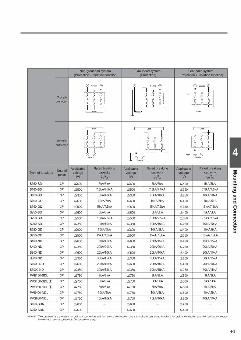
S160-SD 3P ≦600 ≦600 ≦400
S160-SD 3P ≦500 ≦500 ≦350
S160-SD 3P ≦350 ≦350 ≦250
S160-GD 3P ≦600 ≦600 ≦400
S160-GD 3P ≦500 ≦500 ≦350
S250-SD 3P ≦600 ≦600 ≦400
S250-SD 3P ≦500 ≦500 ≦350
S250-SD 3P ≦350 ≦350 ≦250
S250-GD 3P ≦600 ≦600 ≦400
S250-GD 3P ≦500 ≦500 ≦350
S400-ND 3P ≦600 ≦600 ≦400
S400-ND 3P ≦350 ≦350 ≦250
S800-ND 3P ≦600 ≦600 ≦400
S800-ND 3P ≦350 ≦350 ≦250
S1000-ND 3P ≦600 ≦600 ≦400
S1000-ND 3P ≦350 ≦350 ≦250
PVS160-SDL ① 3P ≦750 ≦750 ≦500
PVS250-SDL ① 3P ≦750 ≦750 ≦500
PVS400-NDL 3P ≦750 ≦750 ≦500
PVS800-NDL 3P ≦750 ≦750 ≦500
S160-SDN 3P ≦600 ≦600 ≦400
S250-SDN 3P ≦600 ≦600 ≦400
Grounded system(Protection)
Grounded system(Protection + Isolation function)
Rated breakingcapacityIcu/Ics
Rated breakingcapacityIcu/Ics
Rated breakingcapacityIcu/Ics
5kA/5kA 5kA/5kA 5kA/5kA
7.5kA/7.5kA 7.5kA/7.5kA 7.5kA/7.5kA
10kA/10kA 10kA/10kA 10kA/10kA
10kA/5kA 10kA/5kA 10kA/5kA
15kA/7.5kA 15kA/7.5kA 15kA/7.5kA
5kA/5kA 5kA/5kA 5kA/5kA
7.5kA/7.5kA 7.5kA/7.5kA 7.5kA/7.5kA
10kA/10kA 10kA/10kA 10kA/10kA
10kA/5kA 10kA/5kA 10kA/5kA
15kA/7.5kA 15kA/7.5kA 15kA/7.5kA
15kA/15kA 15kA/15kA 15kA/15kA
20kA/20kA 20kA/20kA 20kA/20kA
20kA/10kA 20kA/10kA 20kA/10kA
30kA/15kA 30kA/15kA 30kA/15kA
20kA/10kA 20kA/10kA 20kA/10kA
30kA/15kA 30kA/15kA 30kA/15kA
5kA/5kA 5kA/5kA 5kA/5kA
5kA/5kA 5kA/5kA 5kA/5kA
10kA/5kA 10kA/5kA 10kA/5kA
10kA/10kA 10kA/10kA 10kA/10kA
― ― ―
― ― ―
4-3
4
Mo
un
ting
and
Co
nn
ection
Note ①:Two breakers are available for ordlnary connection and for reverse connection. Use the ordinally connected breakers for ordinal connection and the reverse connectedbreakers for reverse connection. Do not use contrary.
PVE160-SDL 3P ≦750 3kA/3kA ≦750 3kA/3kA ≦500 3kA/3kA
4-4
Connection of conductors to DC circuit breakers
Type of breakersNo.s ofpoles
Applicable voltage
(V)
Non-grounded system(Protection + Isolation function)
Applicable voltage
(V)
Ordinallyconnection
Source
Load
Source
Load
Source
Load
Applicable voltage
(V)
XS3200ND 3P ≦500 ≦500 ≦350
Grounded system(Protection)
Grounded system(Protection + Isolation function)
Rated breakingcapacityIcu/Ics
Rated breakingcapacityIcu/Ics
Rated breakingcapacityIcu/Ics
50kA/25kA 50kA/25kA 50kA/25kA
XS2000ND 3P ≦500 50kA/25kA ≦500 50kA/25kA ≦350 50kA/25kA
XS2500ND 3P ≦600 20kA/15kA ≦600 20kA/15kA ≦400 20kA/15kA
XS2500ND 3P ≦500 50kA/25kA ≦500 50kA/25kA ≦350 50kA/25kA
XS3200ND 3P ≦600 20kA/15kA ≦600 20kA/15kA ≦400 20kA/15kA
XS1250ND 3P ≦600 20kA/15kA ≦600 20kA/15kA ≦400 20kA/15kA
XS1250ND 3P ≦500 50kA/25kA ≦500 50kA/25kA ≦350 50kA/25kA
XS1600ND 3P ≦600 20kA/15kA ≦600 20kA/15kA ≦400 20kA/15kA
XS1600ND 3P ≦500 50kA/25kA ≦500 50kA/25kA ≦350 50kA/25kA
XS2000ND 3P ≦600 20kA/15kA ≦600 20kA/15kA ≦400 20kA/15kA
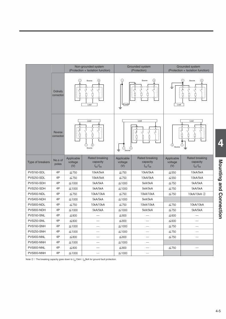
Type of breakersNo.s ofpoles
Applicable voltage
(V)
Non-grounded system(Protection + Isolation function)
Applicable voltage
(V)
Ordinallyconnection
Source
Load
Source
Load
Source
Load
Applicable voltage
(V)
PVS800-NNH 4P ≦1000 ≦1000
Grounded system(Protection)
Grounded system(Protection + Isolation function)
Rated breakingcapacityIcu/Ics
Rated breakingcapacityIcu/Ics
Rated breakingcapacityIcu/Ics
― ―
PVS250-SNL 4P ≦800 ― ≦800 ― ≦600 ―
PVS400-NNL 4P ≦800 ― ≦800 ― ≦750 ―
PVS400-NNH 4P ≦1000 ― ≦1000 ―
PVS800-NNL 4P ≦800 ― ≦800 ― ≦750 ―
PVS160-SDL 4P ≦750 10kA/5kA ≦750 10kA/5kA ≦550 10kA/5kA
PVS400-NDL 4P ≦750 10kA/10kA ≦750 10kA/10kA ≦750 10kA/10kA ②
PVS400-NDH 4P ≦1000 5kA/5kA ≦1000 5kA/5kA
PVS800-NDL 4P ≦750 10kA/10kA ≦750 10kA/10kA ≦750 10kA/10kA
PVS800-NDH 4P ≦1000 5kA/5kA ≦1000 5kA/5kA ≦750 5kA/5kA
Reverseconnection
Source
Load
Source
Load
Source
Load
PVS250-SDL 4P ≦750 10kA/5kA ≦750 10kA/5kA ≦550 10kA/5kA
PVS160-SDH 4P ≦1000 5kA/5kA ≦1000 5kA/5kA ≦750 5kA/5kA
PVS250-SDH 4P ≦1000 5kA/5kA ≦1000 5kA/5kA ≦750 5kA/5kA
PVS160-SNL 4P ≦800 ― ≦800 ― ≦600 ―
PVS160-SNH 4P ≦1000 ― ≦1000 ― ≦750 ―
PVS250-SNH 4P ≦1000 ― ≦1000 ― ≦750 ―
4-5
4
Mo
un
ting
and
Co
nn
ection
Note ②:The breaking capacity goes down to Icu10kA / Ics5kA for ground fault protection.
4-6
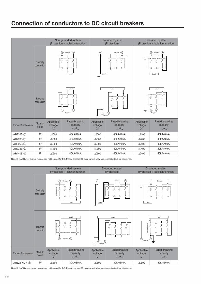
Connection of conductors to DC circuit breakers
Type of breakersNo.s ofpoles
Applicable voltage
(V)
Non-grounded system(Protection + Isolation function)
Applicable voltage
(V)
Ordinallyconnection
Source
Load
Source
Load
Source
Load
Reverseconnection
Source
Load
Source
Load
Source
Load
Applicable voltage
(V)
Note ③:AGR over-current release can not be used for DC. Please prepare DC over-current relay and connect with shunt trip device.
Grounded system(Protection)
Grounded system(Protection + Isolation function)
Rated breakingcapacityIcu/Ics
Rated breakingcapacityIcu/Ics
Rated breakingcapacityIcu/Ics
AR325-NDH ③ 4P ≦800 30kA/30kA ≦800 30kA/30kA ≦600 30kA/30kA
Type of breakersNo.s ofpoles
Applicable voltage
(V)
Non-grounded system(Protection + Isolation function)
Applicable voltage
(V)
Ordinallyconnection
Source
Load
Source
Load
Source
Load
Reverseconnection
Source
Load
Source
Load
Source
Load
Applicable voltage
(V)
AR216S ③
Note ③:AGR over-current release can not be used for DC. Please prepare DC over-current relay and connect with shunt trip device.
3P ≦600 ≦600 ≦400
Grounded system(Protection)
Grounded system(Protection + Isolation function)
Rated breakingcapacityIcu/Ics
Rated breakingcapacityIcu/Ics
Rated breakingcapacityIcu/Ics
40kA/40kA 40kA/40kA 40kA/40kA
AR220S ③ 3P ≦600 40kA/40kA ≦600 40kA/40kA ≦400 40kA/40kA
AR325S ③ 3P ≦600 40kA/40kA ≦600 40kA/40kA ≦400 40kA/40kA
AR440S ③ 3P ≦600 40kA/40kA ≦600 40kA/40kA ≦400 40kA/40kA
AR332S ③ 3P ≦600 40kA/40kA ≦600 40kA/40kA ≦400 40kA/40kA

4-7
4
Mo
un
ting
and
Co
nn
ection
Insulation distance DC600V or less
The insulation distances between the breaker and earthed metal parts and insulators shown in the table below must be
maintained to prevent arcing faults occurring due to conductive ionised gas. In addition, any exposed line-side conductors
must be completely covered, right up the breaker casing or to below the height protected by any interpole barriers. This can
done by using an insulation tube or tape, in order to provide positive protection against short circuit or ground fault due to
metal chipping, surge voltage, dust particles or salt. If terminal covers are not being used, the interpole barriers supplied with
the breaker as standard must be used.
A . Distance from lower breaker to exposed live part of upper breaker terminal (front connection) or distance fromlower breaker to end face of upper breaker (rear connection).
B1. Distance from end face of breaker to top plate.B2. Distance from end face of breaker to insulation plate.C . Gap between breakers.D . Distance from side of breaker to side plate (earthed metal).E . Dimension of insulation over exposed conductors.
Front connection, terminal screw
Front connection, extension bar
Rear connection, Plug-in
B1
A
B2
B1
A
B2
B1 E
D
C
A
B2
Insulation plate
Insulation tube or tape
Top plate (earthed metal)
Side plate
Interpole barrier(Insulation tube or tape is also acceptable)
Insulating tube or tape
Interpole barrier
Sheathed wire
Interpole barrier
Line side
Load side
Exposedconductor
Compressionterminal
Notes:①. Required to allow free and uninterrupted flow of arc gases. Ensure additional clearance or insulation distance if required to perform wiring, barrier installation or electrical work or to meet
the need for more insulation distance between bare live parts and grounded metal members in a switchboard or the like.②. The figures are for lower breakers.③. When the accessories are fitted it is not possible to set close.④. For front connected breakers, insulate all exposed conductors of the line side until the breaker end. If interpole barriers are packed, be sure to use the barriers; more over, insulate all
exposed conductors by insulating tape or the like so that the tape overlaps with the barriers.⑤. Be sure to install the terminal covers (supplied as standard) on the line side of the breakers.✽. If using extension bars (optional), ensure the insulation distance specified for the application.
Moulded Case Circuit Breakers B1 B2 D E
S400-ND 120 80 〃 80 〃XS1250ND XS2500ND 150 100 〃 100 〃
A Note ②
S800-ND S1000-ND 150
XS1600ND XS2000ND 150
Insulation distance, mm (DC 600 V or less) Note ①
S160-SD S160-GD S160-SDN ⑤ 50 50 50 ✽Possible to set close
Note ③25
Not less than the length ofthe bare live part Note④
S250-SD S250-GD S250-SDN ⑤ 65 65 65 ✽ 〃 50 〃
C
XS3200ND
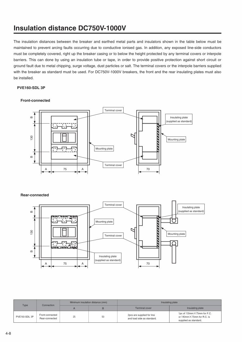
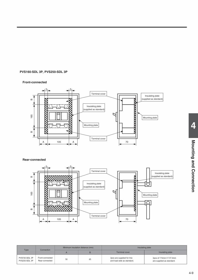
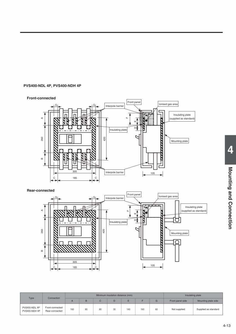
Insulation distance DC750V-1000V
The insulation distances between the breaker and earthed metal parts and insulators shown in the table below must be
maintained to prevent arcing faults occurring due to conductive ionised gas. In addition, any exposed line-side conductors
must be completely covered, right up the breaker casing or to below the height protected by any terminal covers or interpole
barriers. This can done by using an insulation tube or tape, in order to provide positive protection against short circuit or
ground fault due to metal chipping, surge voltage, dust particles or salt. The terminal covers or the interpole barriers supplied
with the breaker as standard must be used. For DC750V-1000V breakers, the front and the rear insulating plates must also
be installed.
B13
0B
A 75 70
70
A
B13
0B
A 75 A
Terminal cover
Terminal cover
Insulating plate
(supplied as standard)
Mounting plate
Insulating plate
(supplied as standard)
Mounting plate
Mounting plate
Terminal cover
Terminal cover
Insulating plate
(supplied as standard)
Mounting plate
PVE160-SDL 3P
Front-connected
Rear-connected
Type Connection
PVE160-SDL 3PFront-connectedRear-connected
25
Minimum insulation distance (mm) Insulating plate
A B Terminal cover
502pcs are supplied for line and load side as standard.
Insulating plate
1pc of 130mm×75mm for F.C.or 140mm×75mm for R.C. is supplied as standard.
4-8
4-9
4
Mo
un
ting
and
Co
nn
ection
5 5
B16
5B
A 105 70
70
A
5 5
B16
5B
A 105 A
Terminal cover
Terminal cover
Insulating plate
(supplied as standard)
Mounting plate
Insulating plate
(supplied as standard)
Mounting plate
Insulating plate
(supplied as standard)
Mounting plate
Terminal cover
Terminal cover
Insulating plate
(supplied as standard)
Mounting plate
Type Connection
PVS160-SDL 3PPVS250-SDL 3P
Front-connectedRear-connected
50
Minimum insulation distance (mm) Insulating plate
A B Terminal cover
652pcs are supplied for line and load side as standard.
Insulating plate
2pcs of 115mm×137.5mm are supplied as standard.
PVS160-SDL 3P, PVS250-SDL 3P
Front-connected
Rear-connected
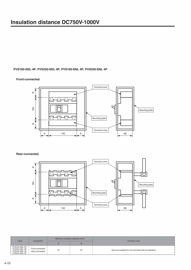
4-10
Insulation distance DC750V-1000V
B16
5B
A 140 68
68
A
B16
5B
A 140 A
Terminal cover
Terminal cover
Mounting plate
Mounting plate
Terminal cover
Terminal cover
Mounting plate
Mounting plate
Type Connection
PVS160-SDL 4PPVS250-SDL 4PPVS160-SNL 4PPVS250-SNL 4P
Front-connectedRear-connected
50
Minimum insulation distance (mm)Terminal cover
A B
65 2pcs are supplied for line and load side as standard.
PVS160-SDL 4P, PVS250-SDL 4P, PVS160-SNL 4P, PVS250-SNL 4P
Front-connected
Rear-connected
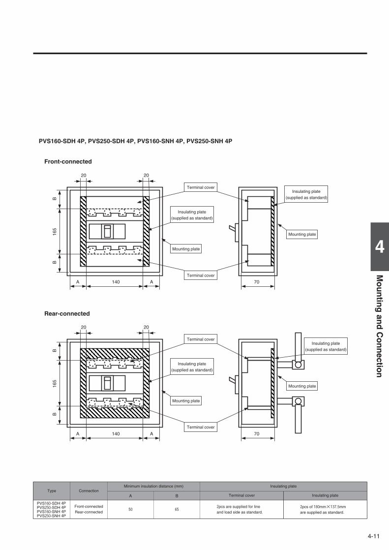
4-11
4
Mo
un
ting
and
Co
nn
ection
20 20
B16
5B
A 140 70
70
A
20 20
B16
5B
A 140 A
Terminal cover
Terminal cover
Insulating plate
(supplied as standard)
Mounting plate
Insulating plate
(supplied as standard)
Mounting plate
Insulating plate
(supplied as standard)
Mounting plate
Terminal cover
Terminal cover
Insulating plate
(supplied as standard)
Mounting plate
PVS160-SDH 4P, PVS250-SDH 4P, PVS160-SNH 4P, PVS250-SNH 4P
Front-connected
Rear-connected
Type Connection
PVS160-SDH 4PPVS250-SDH 4PPVS160-SNH 4PPVS250-SNH 4P
Front-connectedRear-connected
50
Minimum insulation distance (mm) Insulating plate
A B Terminal cover
652pcs are supplied for line and load side as standard.
Insulating plate
2pcs of 180mm×137.5mm are supplied as standard.
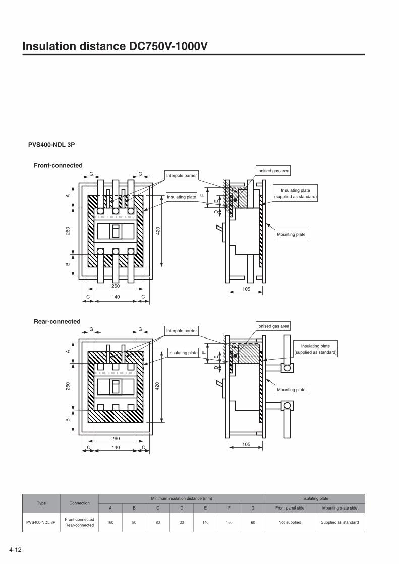
4-12
Insulation distance DC750V-1000V
PVS400-NDL 3P
Front-connected
Rear-connected
G G
B26
0
C 140 C
105
F
ED
A
420
420
105
E
F
D
C 140 C
AB
260
GG
260
260
Insulating plate
(supplied as standard)
Insulating plate
(supplied as standard)
Mounting plate
Mounting plate
Ionised gas area
Ionised gas area
Interpole barrier
Insulating plate
Interpole barrier
Insulating plate
Type Connection
PVS400-NDL 3PFront-connectedRear-connected
160 Not supplied Supplied as standard
Minimum insulation distance (mm) Insulating plate
A B C D E F Front panel side Mounting plate side
80 80 30 140 160
G
60
4-13
4
Mo
un
ting
and
Co
nn
ection
G G
B26
0
C 185 C
105
F
ED
A
420
420
105
E
F
D
C 185 C
AB
260
GG
305
305
Ionised gas area
Ionised gas area
Interpole barrier
Front panel
Front panel
Insulating plate
(supplied as standard)
Insulating plate
(supplied as standard)
Mounting plate
Mounting plate
Interpole barrier
Interpole barrier
Insulating plate
Insulating plate
Type Connection
PVS400-NDL 4PPVS400-NDH 4P
Front-connectedRear-connected
160 Not supplied Supplied as standard
PVS400-NDL 4P, PVS400-NDH 4P
Front-connected
Rear-connected
Minimum insulation distance (mm) Insulating plate
A B C D E F Front panel side Mounting plate side
80 80 30 140 160
G
60
4-14
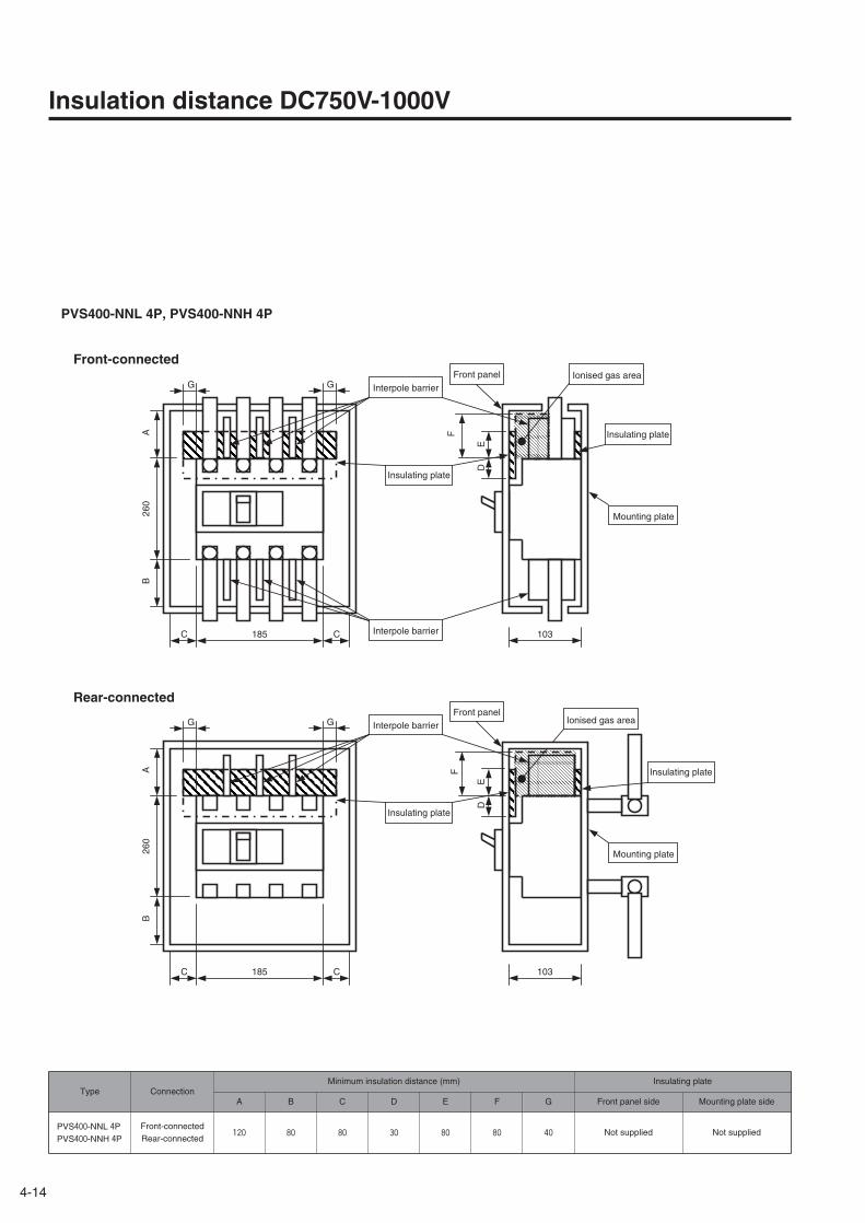
Insulation distance DC750V-1000V
G G
AB
260
C 185 C 103
F
ED
103
E
F
D
C 185 C
GG
AB
260
Interpole barrier
Interpole barrier
Interpole barrier
Insulating plate
Insulating plate
Insulating plate
Insulating plate
Front panel
Front panel
Ionised gas area
Ionised gas area
Mounting plate
Mounting plate
Type Connection
PVS400-NNL 4PPVS400-NNH 4P
Front-connectedRear-connected
120 Not supplied Not supplied
PVS400-NNL 4P, PVS400-NNH 4P
Front-connected
Rear-connected
Minimum insulation distance (mm) Insulating plate
A B C D E F Front panel side Mounting plate side
80 80 30 80 80
G
40
4-15
4
Mo
un
ting
and
Co
nn
ection
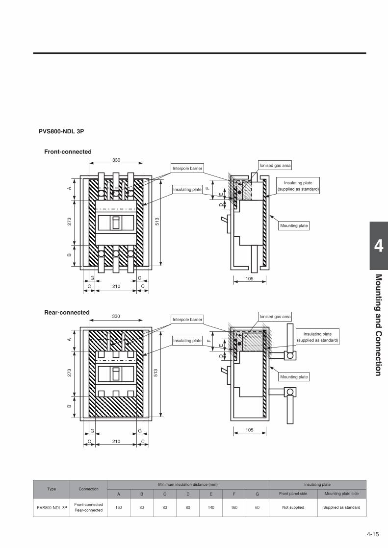
Front-connected
Rear-connected
513
105
E
F
D
C 210 C
AB
273
330
G G
B27
3
C 210 C
105
F
ED
A
513
330
G G
Insulating plate
(supplied as standard)
Mounting plate
Ionised gas area
Insulating plate
(supplied as standard)
Mounting plate
Ionised gas area
Interpole barrier
Insulating plate
Interpole barrier
Insulating plate
Type Connection
PVS800-NDL 3PFront-connectedRear-connected
160 Not supplied Supplied as standard
PVS800-NDL 3P
Minimum insulation distance (mm) Insulating plate
A B C D E F Front panel side Mounting plate side
80 80 80 140 160
G
60
4-16
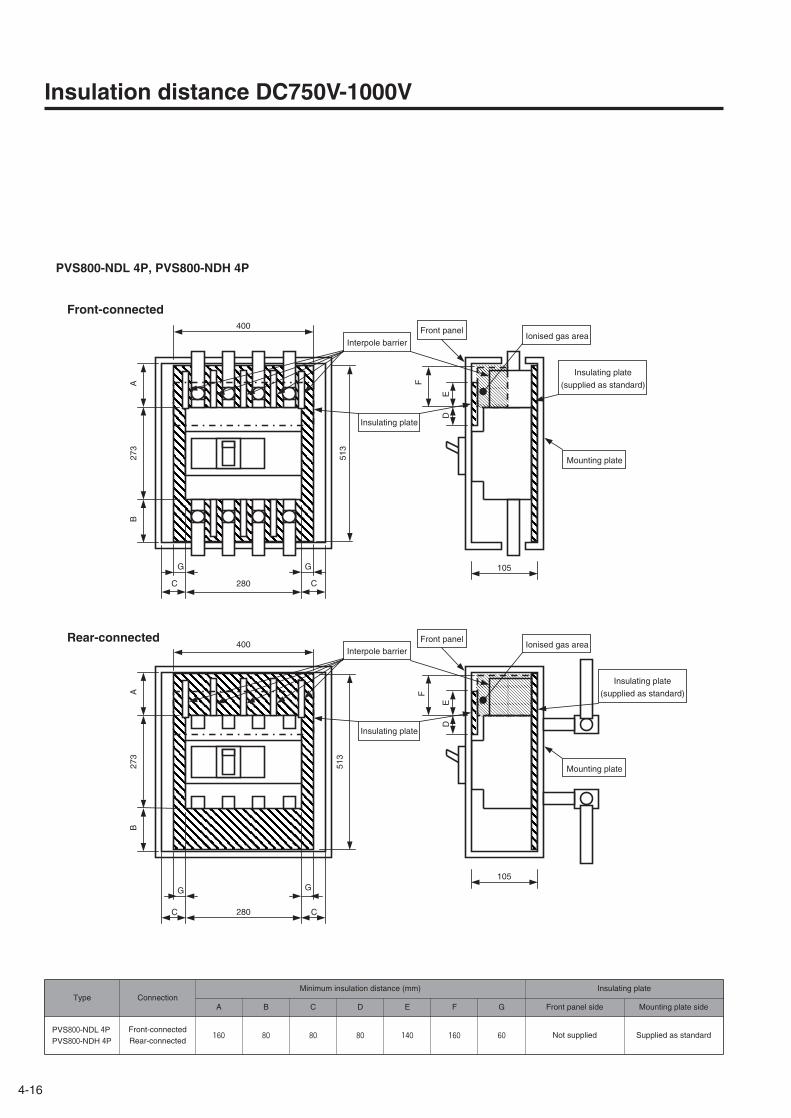
Insulation distance DC750V-1000V
513
105
E
F
D
C 280 C
AB
273
400
G G
B27
3
C 280 C
105
F
ED
A
513
400
G G
Interpole barrier
Interpole barrier
Insulating plate
Insulating plate
Ionised gas areaFront panel
Front panel
Insulating plate
(supplied as standard)
Mounting plate
Ionised gas area
Insulating plate
(supplied as standard)
Mounting plate
Type Connection
PVS800-NDL 4PPVS800-NDH 4P
Front-connectedRear-connected
160 Not supplied Supplied as standard
PVS800-NDL 4P, PVS800-NDH 4P
Front-connected
Rear-connected
Minimum insulation distance (mm) Insulating plate
A B C D E F Front panel side Mounting plate side
80 80 80 140 160
G
60
4-17
4
Mo
un
ting
and
Co
nn
ection
103
E
F
D
C 280 C
AB
273
400
G G
B27
3
C 280 C
103
F
ED
A
400
G G
Interpole barrier
Interpole barrier
Insulating plate
Insulating plate
Insulating plate
Ionised gas areaFront panel
Mounting plate
Ionised gas areaFront panel
Mounting plate
Insulating plate
(supplied as standard)
Type Connection
PVS800-NNL 4PPVS800-NNH 4P
Front-connectedRear-connected
120 Not supplied Not supplied
PVS800-NNL 4P, PVS800-NNH 4P
Front-connected
Rear-connected
Minimum insulation distance (mm) Insulating plate
A B C D E F Front panel side Mounting plate side
80 80 80 80 80
G
60

5-1
5
Ou
tline
Dim
ensio
ns
5DC Air Circuit Breakers Outline Dimensions
AR216S, AR220S 3P …………………………………………………………5-2AR325S, AR332S 3P …………………………………………………………5-4AR325-NDH 4P…………………………………………………………………5-6AR440SB 3P……………………………………………………………………5-8AR440S 3P ……………………………………………………………………5-10
DC Moulded Case Circuit Breakers Outline DimensionsS160-SD, S160-GD, S160-SDN, S250-SD, S250-GD, S250-SDN 3P …5-12S400-ND 3P …………………………………………………………………5-13S800-ND 3P …………………………………………………………………5-13S1000-ND 2P, 3P ……………………………………………………………5-14XS1250ND 2P, 3P ……………………………………………………………5-15XS1600ND 2P, 3P ……………………………………………………………5-16XS2000ND 2P, 3P ……………………………………………………………5-17XS2500ND, XS3200ND 2P, 3P ……………………………………………5-18PVE160-SDL 3P………………………………………………………………5-19PVS160-SDL, PVS250-SDL 3P ……………………………………………5-20PVS160-SDL, PVS250-SDL, PVS160-SNL, PVS250-SNL 4P …………5-20PVS160-SDH, PVS250-SDH, PVS160-SNH, PVS250-SNH 4P ………5-21PVS400-NDL 3P………………………………………………………………5-22PVS400-NDL, PVS400-NDH 4P ……………………………………………5-23PVS400-NNL, PVS400-NNH 4P ……………………………………………5-23PVS800-NDL 3P………………………………………………………………5-24PVS800-NDL, PVS800-NDH 4P ……………………………………………5-25PVS800-NNL, PVS800-NNH 4P ……………………………………………5-25
OutlineDimensions
5-2
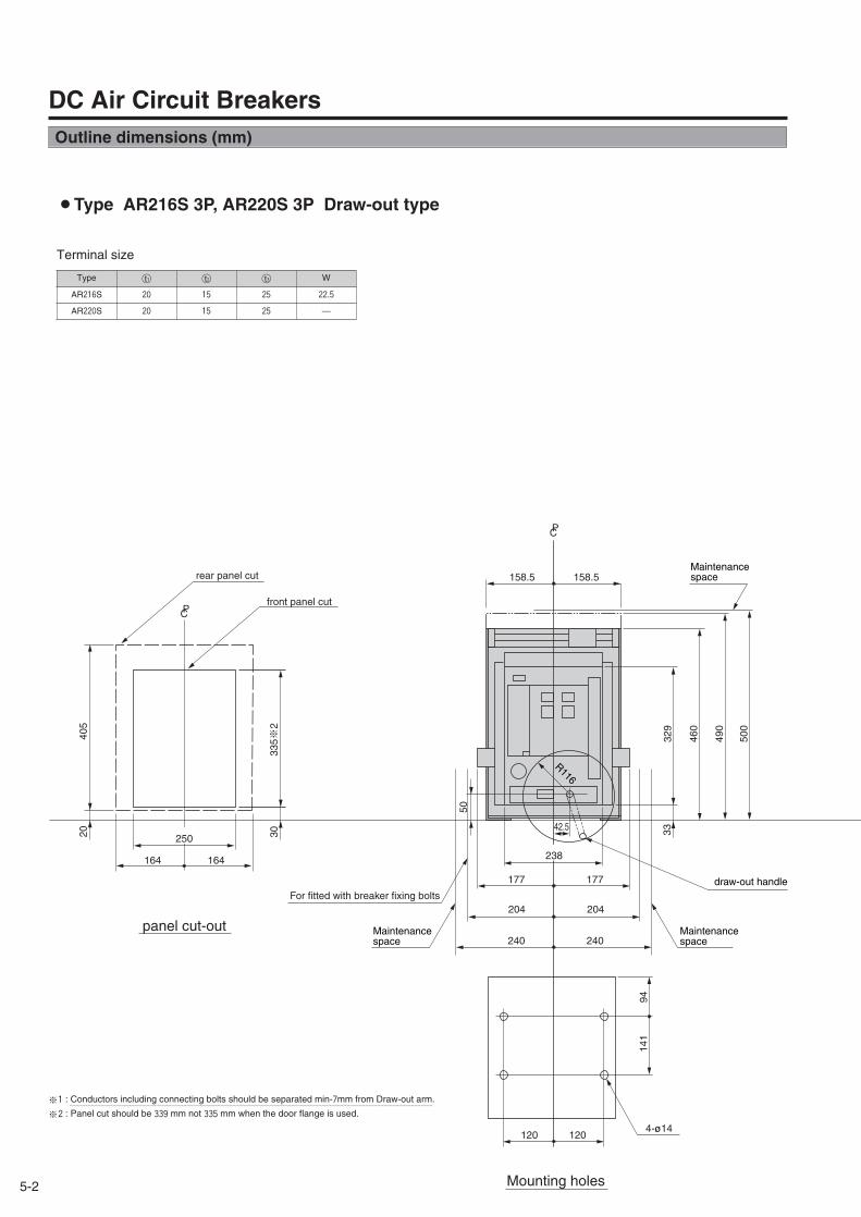
※1 : Conductors including connecting bolts should be separated min-7mm from Draw-out arm.
※2 : Panel cut should be 339 mm not 335 mm when the door flange is used.~~~~~~~~~~~~~~~~~~~~~~~~~~~~~~~~~~~~~~~~~~~~~~~~~~~~~~~~~~~
405
20
335※2
30
164
PC
PC
164
177 177
329
460
490
3342.5
50
120 120
141
94
4-ø14
238
500
204 204
240 240
250
R116
158.5158.5rear panel cut
front panel cut
panel cut-out
For fitted with breaker fixing boltsdraw-out handle
Maintenancespace
Maintenancespace
Maintenancespace
Mounting holes
DC Air Circuit Breakers
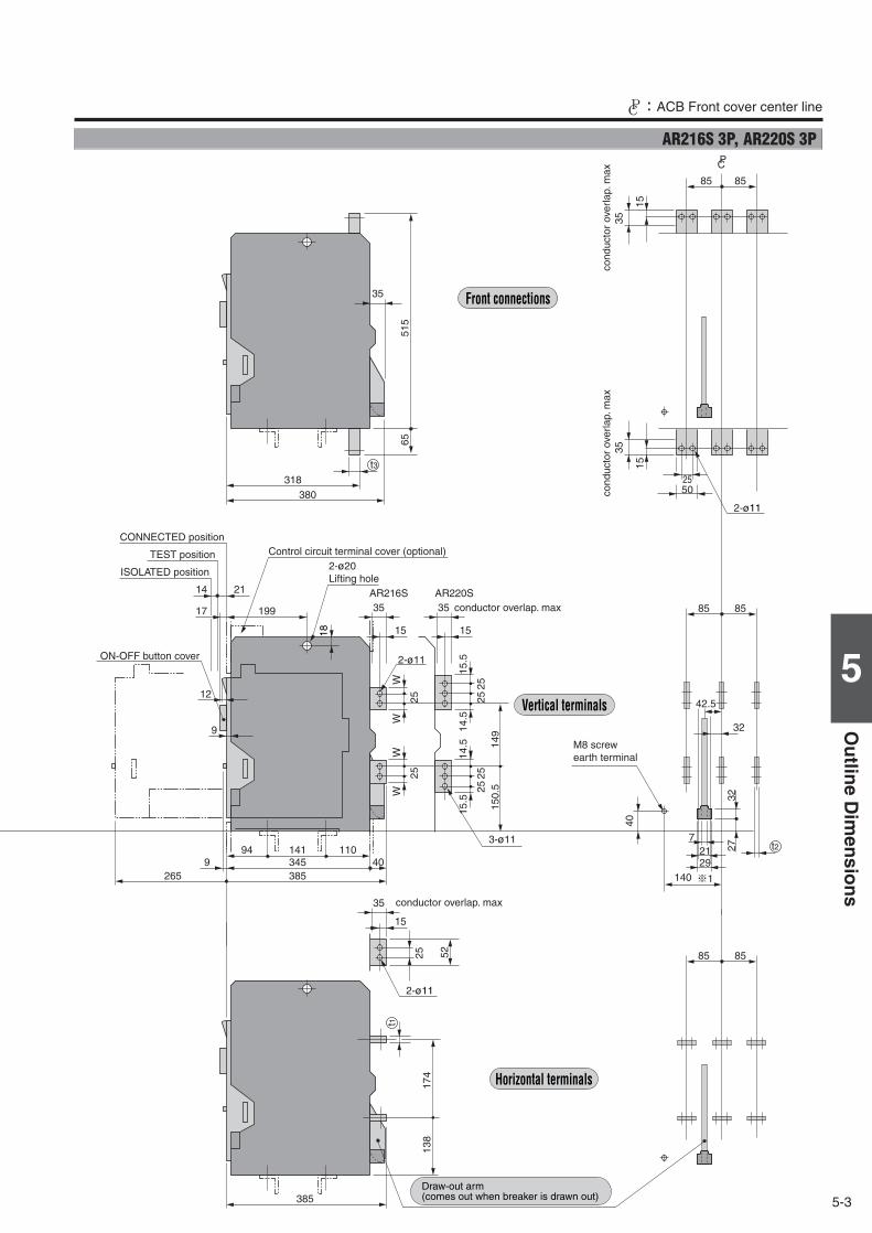
¡Type AR216S 3P, AR220S 3P Draw-out type
Terminal size
Type t1○ t2○ t3○ W
AR216S 20 15 25 22.5
AR220S 20 15 25 ―
Outline dimensions (mm)
5-3
5
Ou
tline
Dim
ensio
ns
CP:ACB Front cover center line
3-ø11
345 40385
9265
141
17 199
9
14 21
35AR216S AR220S
15
2525
2525W
W
94 110
35
15
WW
15.5
14.5
149
150.
52525
14.5
15.5
35
15
25 52
2-ø11
318380
35
6551
5
PC
15
85 85
3535
15
2550
385
174
138
2-ø11
2-ø11
18
t1
85 85
85 85
42.5
32
721
¶1
t2
140
40
t3
12
29
2732
cond
ucto
r ov
erla
p. m
axconductor overlap. max
conductor overlap. max
2-ø20Lifting hole
M8 screwearth terminal
Front connections
Vertical terminals
Horizontal terminals
Draw-out arm(comes out when breaker is drawn out)
CONNECTED position
TEST position
ISOLATED position
ON-OFF button cover
Control circuit terminal cover (optional)
cond
ucto
r ov
erla
p. m
ax
AR216S 3P, AR220S 3P
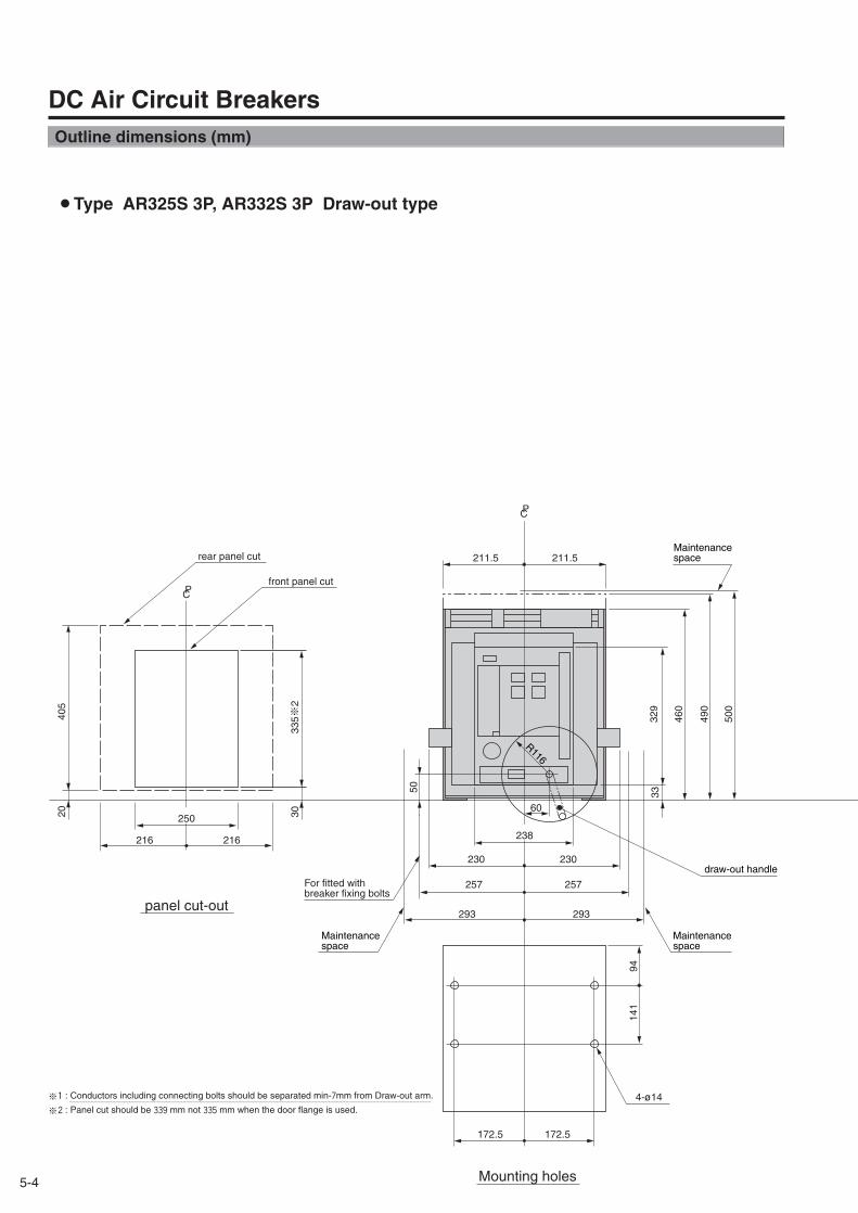
5-4
405
20
335※2
30
216
PC
PC
216
230 230
329
460
490
33
293 293
60
50
172.5 172.5
141
94
4-ø14
238
500
257 257
250
R116
211.5211.5rear panel cut
front panel cut
For fitted with breaker fixing bolts
draw-out handle
Maintenancespace
Maintenancespace
Maintenancespace
panel cut-out
Mounting holes
¡Type AR325S 3P, AR332S 3P Draw-out type
DC Air Circuit Breakers
※1 : Conductors including connecting bolts should be separated min-7mm from Draw-out arm.
※2 : Panel cut should be 339 mm not 335 mm when the door flange is used.~~~~~~~~~~~~~~~~~~~~~~~~~~~~~~~~~~~~~~~~~~~~~~~~~~~~~~~~~~~
Outline dimensions (mm)
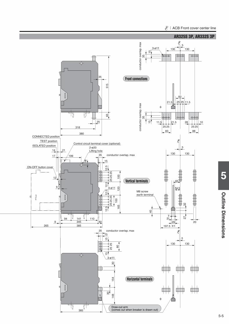
5-5
5
Ou
tline
Dim
ensio
ns
CP:ACB Front cover center line
PC
PC
345 40
197.5
130 130
5
20385
9265
141
17 199
9
14 21
35
15
12.5
12.5
2525
25
94 110
3515
1515
25
80
25
12.5
12.5
25 100
165
40
120
100
2525
15
35
28 10
25 25
88318
25
380
130 130
6551
5
PC5
15
3-ø11
35
11.521.5 25 25
83
65
385
130 130
5
154
14830
30
3-ø11
18
7
54.5
21
¶1
11.5 21.5
25 25
83
12
35
29
2732
4-ø11
conductor overlap. max
conductor overlap. max
2-ø20Lifting hole
M8 screwearth terminal
Front connections
Vertical terminals
Horizontal terminals
Draw-out arm(comes out when breaker is drawn out)
CONNECTED position
TEST position
ISOLATED position
ON-OFF button cover
Control circuit terminal cover (optional)co
nduc
tor
over
lap.
max
cond
ucto
r ov
erla
p. m
ax
AR325S 3P, AR332S 3P
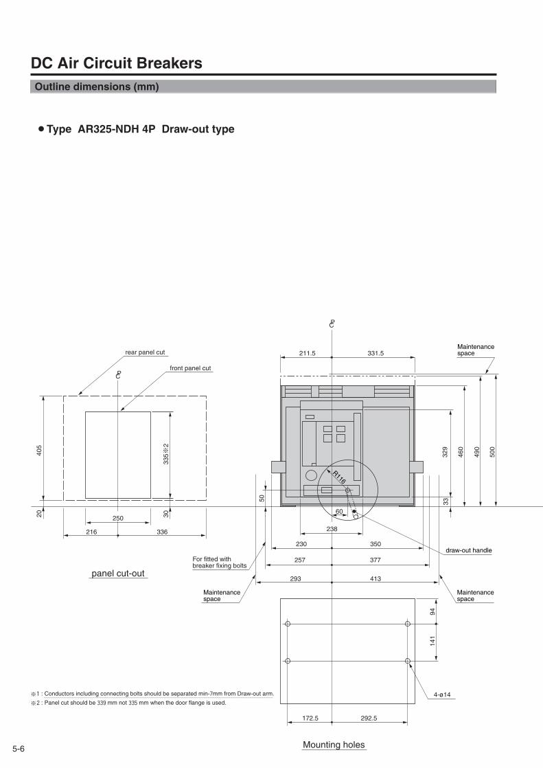
5-6
405
20
335※2
30
216
PC
PC
336
230 350
329
460
490
33
293 413
60
50
172.5 292.5
141
94
4-ø14
238
500
257 377
250
R116
331.5211.5
panel cut-out
Mounting holes
rear panel cut
front panel cut
Maintenancespace
Maintenancespace
Maintenancespace
draw-out handleFor fitted with breaker fixing bolts
¡Type AR325-NDH 4P Draw-out type
DC Air Circuit Breakers
※1 : Conductors including connecting bolts should be separated min-7mm from Draw-out arm.
※2 : Panel cut should be 339 mm not 335 mm when the door flange is used.~~~~~~~~~~~~~~~~~~~~~~~~~~~~~~~~~~~~~~~~~~~~~~~~~~~~~~~~~~~
Outline dimensions (mm)
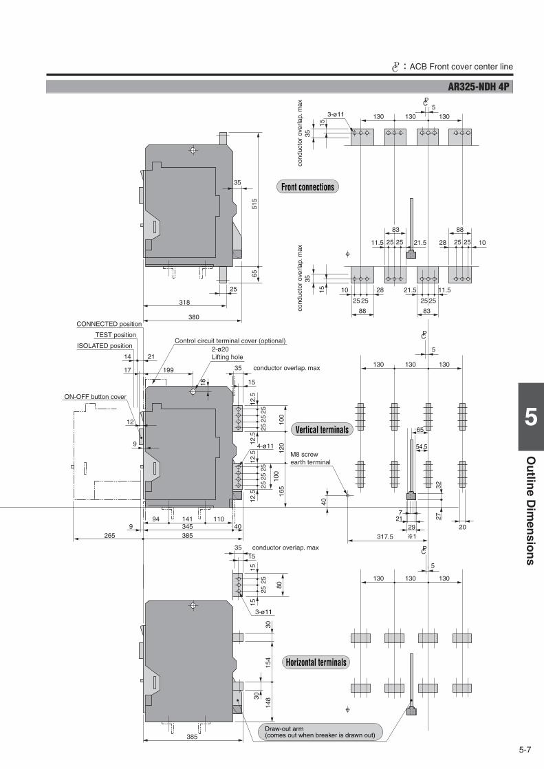
5-7
5
Ou
tline
Dim
ensio
ns
CP:ACB Front cover center line
PC
PC
345 40
317.5
130 130 130
5
20385
9265
141
17 199
9
14 21
35
15
12.5
12.5
2525
25
94 110
3515
1515
25
80
25
12.5
12.5
25 100
165
40
120
100
2525
2810
2525
15
3588
11.521.5
2525
83
28 102525
318
25
380
130 130 130
6551
5
88
11.5 21.52525
PC5
15
3-ø11
35
83
65
385
130 130 130
5
154
14830
30
3-ø11
18
7
54.5
21
¶1
12
35
29
2732
4-ø11
conductor overlap. max
conductor overlap. max
M8 screwearth terminal
CONNECTED position
TEST position
ISOLATED position
ON-OFF button cover
2-ø20Lifting hole
Control circuit terminal cover (optional)
cond
ucto
r ov
erla
p. m
axco
nduc
tor
over
lap.
max
Front connections
Vertical terminals
Horizontal terminals
Draw-out arm(comes out when breaker is drawn out)
AR325-NDH 4P
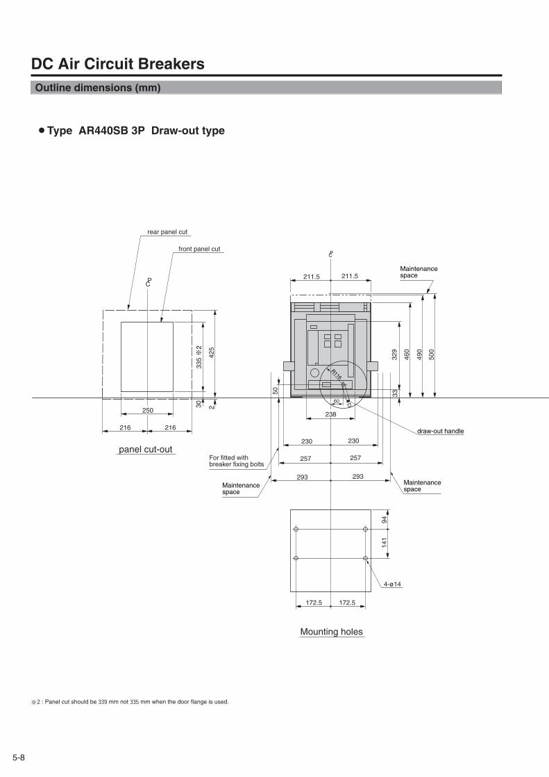
5-8
P
425
335 ※2
250
216
2
216
30
C211.5211.5
PC
230 230
329
460
490
33
293 293
60
50
172.5 172.5
141
94
4-ø14
238
500
257 257
R116
Maintenancespace
rear panel cut
front panel cut
panel cut-out
Mounting holes
Maintenancespace
Maintenancespace
For fitted with breaker fixing bolts
draw-out handle
¡Type AR440SB 3P Draw-out type
DC Air Circuit Breakers
※2 : Panel cut should be 339 mm not 335 mm when the door flange is used.
Outline dimensions (mm)
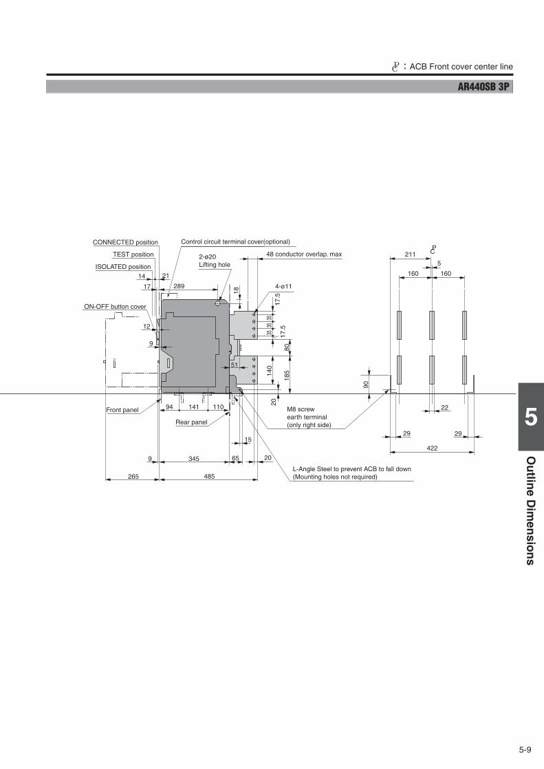
5-9
5
Ou
tline
Dim
ensio
ns
CP:ACB Front cover center line
65
15
20
51
140
185
2929
90
160 160
5
422
211
22
2017
.517
.5
3535
35
PC
4-ø11
L-Angle Steel to prevent ACB to fall down(Mounting holes not required)
3459
265
141
17 289
9
14 21
94 110
18
485
12
80
48 conductor overlap. max
Front panel
Rear panel
M8 screwearth terminal(only right side)
2-ø20Lifting hole
CONNECTED position
TEST position
ISOLATED position
ON-OFF button cover
Control circuit terminal cover(optional)
AR440SB 3P
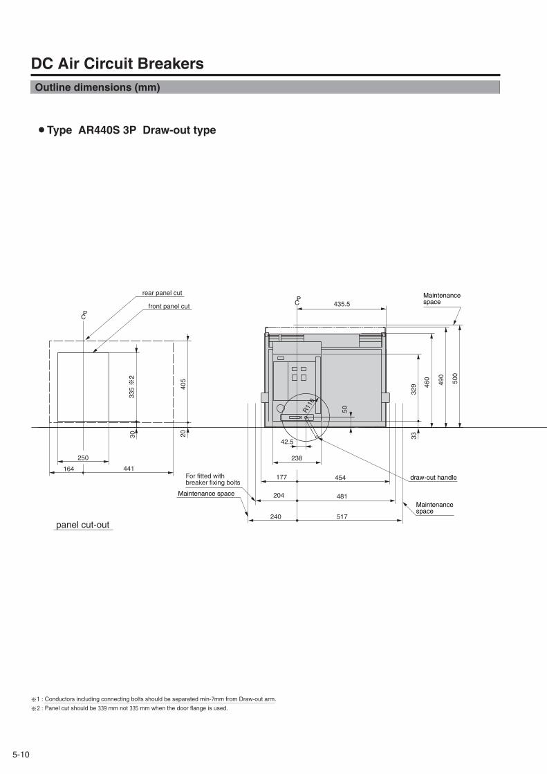
5-10
R11
6
42.5
238250
P
500
490
460
33
441164
405
20
335 ※2
C
329
50
30
PC
177 454
435.5
240 517
204 481
draw-out handle
Maintenance space
panel cut-out
rear panel cut
front panel cut
For fitted with breaker fixing bolts
Maintenancespace
Maintenancespace
¡Type AR440S 3P Draw-out type
DC Air Circuit Breakers
※1 : Conductors including connecting bolts should be separated min-7mm from Draw-out arm.
※2 : Panel cut should be 339 mm not 335 mm when the door flange is used.~~~~~~~~~~~~~~~~~~~~~~~~~~~~~~~~~~~~~~~~~~~~~~~~~~~~~~~~~~~
Outline dimensions (mm)
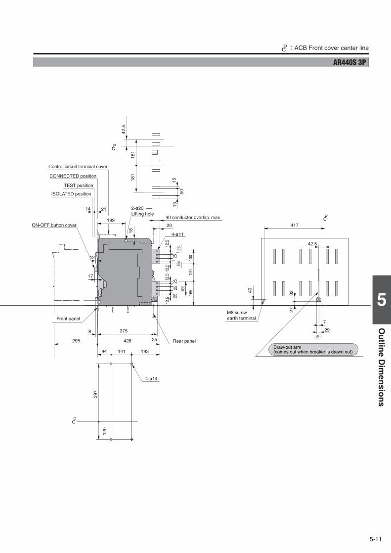
5-11
5
Ou
tline
Dim
ensio
ns
CP:ACB Front cover center line
1515
50
375
295 428
17
9
141 19394
120
397
12.5 25
25 100
100
120
165
2512.5
12.5 25
2525
12.5
20
14 21
199
18
35
PC
PC
PC
181
4042.5
3227
181
7
¶1
12
4-ø14
4-ø11
29
417
42.5
Control circuit terminal cover
40 conductor overlap. max
Rear panel
Front panel
CONNECTED position
TEST position
ISOLATED position
ON-OFF button cover
2-ø20Lifting hole
M8 screwearth terminal
Draw-out arm(comes out when breaker is drawn out)
AR440S 3P
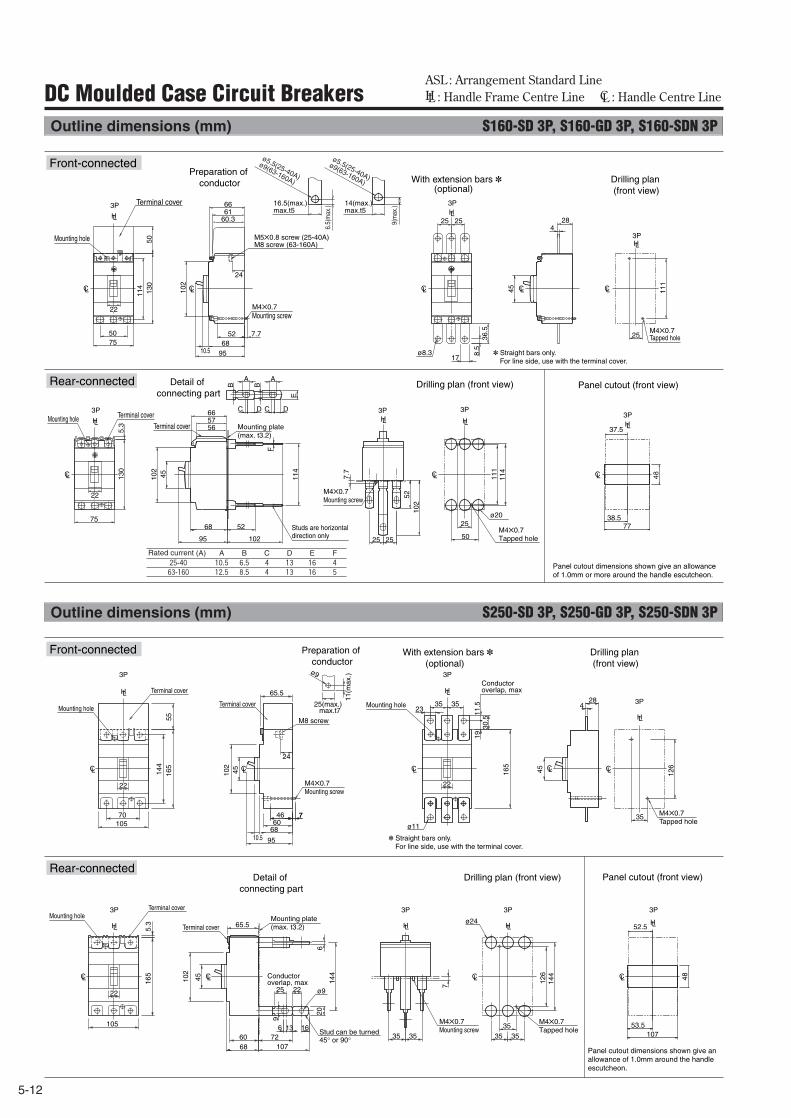
5-12
ASL : Arrangement Standard Line HL : Handle Frame Centre Line CL : Handle Centre LineDC Moulded Case Circuit Breakers
Outline dimensions (mm) S160-SD 3P, S160-GD 3P, S160-SDN 3P
Outline dimensions (mm) S250-SD 3P, S250-GD 3P, S250-SDN 3P
CL CL
LH LHLH
Front-connected
Rear-connected Drilling plan (front view)
M4✕0.7Tapped hole
M4✕0.7Mounting screw
Panel cutout (front view)Detail of connecting part
Mounting plate(max. t3.2)
Studs are horizontaldirection only
Panel cutout dimensions shown give an allowance of 1.0mm or more around the handle escutcheon.
✽ Straight bars only. For line side, use with the terminal cover.
With extension bars ✽ (optional)
Drilling plan (front view)
Preparation of conductor
25
50
C D
E
A
3P
111
114
ø20
37.5
3P
38.577
B
C D
A
B
102
52
114
68
102
F
95
3P
7.7
25 25
102
52
6.5(
max
.)
9(m
ax.)16.5(max.)
max.t514(max.)max.t5
ø5.5(25-40A)
ø9(63-160A)
ø5.5(25-40A)
ø9(63-160A)
45
CL CL CL CLCL
LH LH
LH
M4✕0.7Tapped hole
Terminal cover
M4✕0.7Mounting screw
M5✕0.8 screw (25-40A)M8 screw (63-160A)
257550
102
7.7
24
6661
60.3
9568
52
3P
10.5
3P
5013
0
111
3P
8.5
5.63
17
114
25 25
ø8.3
45
284
CL
LH
75
3P
5.3
130
665756
22
22
Terminal coverTerminal cover
Mounting hole
Mounting hole
48
Rated current (A) A B C D E25-40 10.5 6.5 4 13 16
63-160 12.5 8.5 4 13 16
F4
5
CL CL CLCLCL
CL CL CL
LHLH
LH
CL
LH
LH
LH
LH
7
23
45
3P 3P
3P
3P
ø24
3513
9
7
102
144
144
206
126
ø9
6 3516
6860
10772 3535 35
3P
65.5
65.5
30.5
11.5
19
165
3535
102
5516
514
4
45 126
7 35
24
4610570
25 22
ø11
10.5 95
6860
284
22
3P
5.3
165
105
22
22
25(max.)max.t7
11(m
ax.)ø9
45
3P
Mounting hole
Terminal cover
Mounting holeTerminal cover
Terminal cover
Terminal cover
M8 screw
M4✕0.7Mounting screw
M4✕0.7Tapped hole
Conductoroverlap, max
Mounting hole
✽ Straight bars only. For line side, use with the terminal cover.
Drilling plan (front view)
M4✕0.7Tapped hole
M4✕0.7Mounting screw
Panel cutout (front view)Detail of connecting part
Mounting plate(max. t3.2)
Stud can be turned 45° or 90°
Panel cutout dimensions shown give an allowance of 1.0mm around the handle escutcheon.
Conductor overlap, max
52.5
53.5107
48
Preparation of conductor
With extension bars ✽ (optional)
Drilling plan (front view)
Front-connected
Rear-connected
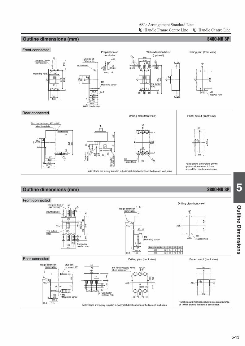
5-13
5
Ou
tline
Dim
ensio
ns
ASL : Arrangement Standard Line HL : Handle Frame Centre Line CL : Handle Centre Line
Outline dimensions (mm) S800-ND 3P
HLHL
HL
HL
HL
ASL ASL
3P
ASL
3P
3P
ASL
ASL
ASL
103 107
28 13
4
145
70 70
13
70 70 43 43
117
1
26
10
42
122
1
03
30.
5
80.5
117
126
3P
ø13
ø48
127.5
R6
ø13
70
140 210
3P
172
40
13
70
80
273
8
0
92
55.
5 4
6.5
117
1
26
141
1
32
t2 L2
t1 L1
103 107
145
28 13
127.5 4
80.5
51
170
90
25
2532
20
158
8
32
L1 L2 t1
32 34 8
32 35 10
t2
8
10
630
800
Front-connected
Drilling plan (front view) Panel cutout (front view)
Drilling plan (front view)
Conductor overlap, max
Conductor overlap, max
Stud can be turned 90°
M8 Tapped hole
M8Mounting screw
Interpole barrier (removable)
Mounting hole
M8Mounting screw
Panel cutout dimensions shown give an allowance of 1.0mm around the handle escutcheon.Note: Studs are factory installed in horizontal direction both on the line and load sides.
Trip button (red)
ø15 for accessory wiring when necessary
Rated Current (A)
Toggle extension(removable)
Toggle extension(removable)
M8 Tapped hole
Rear-connected
Outline dimensions (mm) S400-ND 3P
CL
Drilling plan (front view) Panel cutout (front view)
Front-connected
Rear-connected
Panel cutout dimensions shown give an allowance of 1.0mm around the handle escutcheon.
Preparation of conductor
With extension bars (optional)
Drilling plan (front view)
M10 screw
M6Tapped hole
Interpole barrier (removable)
Mounting hole
M6Mounting screw
(With handle cap)
On side 36Off side 35
Con
duct
or
over
lap
max
.
Con
duct
or
over
lap
max
.
M6Tapped hole
Mounting plateStud can be turned 45° or 90°
Note: Studs are factory installed in horizontal direction both on the line and load sides.
LH
LH
LH
90
116
51
85.3 14.7
8 36
8 35
4597
103107
127.5145
971031074
127.5145
4140
260
102
90
102
90
214
110
228
260
228
830
CLCL
CL
CL CL CL
12(m
ax.)
ø11
ø13
214
228
ø36
30(max.)
max. t10
3PLH
45
90
CL
CL
3PLH
118
92
R6
3P
30 45 45
103
11070
153915
39ø1
3
12028 14
.530 44
.5
3014
.544
.5
ø14 148
44.5
349
260
Trip button (red)
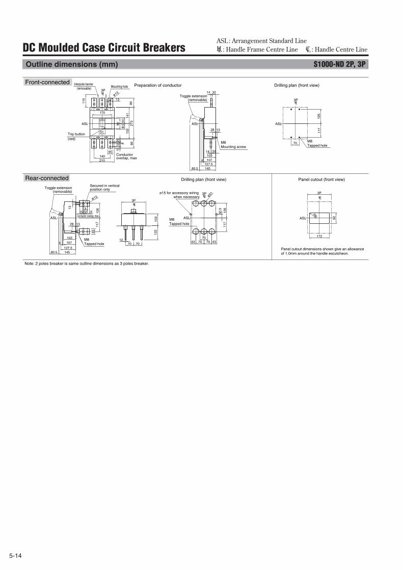
5-14
ASL : Arrangement Standard Line HL : Handle Frame Centre Line CL : Handle Centre LineDC Moulded Case Circuit Breakers
Outline dimensions (mm) S1000-ND 2P, 3P
HL
HL
HL
HL
HL
3P
ASL
ASL
3P
ASL ASL
ASL
3P
ASLR6
ø1311
7
127.5
ø133P
45
ø51 3P
172
70
92
117
1
26
140 210
14 35
14 32
45
13
103 107
145
28 13
127.5 4
80
273
80
15
32 8
25
55.
5 4
6.5 90
141
1
32
80.5
110
103
107
28 13
4
145
70 70 43 43
25 8
32 20
103
117
1
26
30.
5
126
122
13
80.5
51
170
70 12
70 70
Toggle extension(removable)
Toggle extension(removable)
Drilling plan (front view) Panel cutout (front view)
Preparation of conductor Drilling plan (front view)Front-connected
Rear-connected
Conductor overlap, max
Conductor overlap, max
M8 Tapped hole
M8Tapped hole
M8Tapped hole
Interpole barrier (removable) Mounting hole
M8 Mounting screw
Panel cutout dimensions shown give an allowance of 1.0mm around the handle escutcheon.
Trip button (red)
ø15 for accessory wiring when necessary
Secured in vertical position only
Note: 2 poles breaker is same outline dimensions as 3 poles breaker.
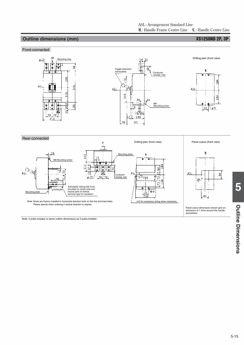
5-15
5
Ou
tline
Dim
ensio
ns
ASL : Arrangement Standard Line HL : Handle Frame Centre Line CL : Handle Centre Line
Outline dimensions (mm) XS1250ND 2P, 3P
Front-connected
Rear-connected
Note: 2 poles breaker is same outline dimensions as 3 poles breaker.
Drilling plan (front view)
Conductor overlap, max
M8Mounting screw
Toggle extension(removable)
Mounting hole
Drilling plan (front view) Panel cutout (front view)
Conductor overlap, max
Mounting plate
M8 Mounting screw
Insulating plate
Panel cutout dimensions shown give an allowance of 1.5mm around the handle escutcheon.
ø15 for accessory wiring when necessary
Soft plastic tubing ø50 to be provided on center pole and neutral pole of vertical terminal type for insulation.
Mounting plate
Note: Studs are factory installed in horizontal direction both on the line and load sides.Please specify when ordering if vertical direction is reqired.
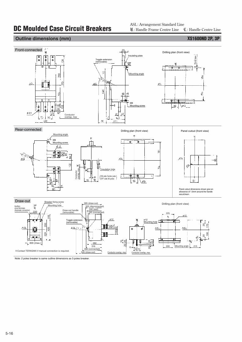
5-16
ASL : Arrangement Standard Line HL : Handle Frame Centre Line CL : Handle Centre LineDC Moulded Case Circuit Breakers
Outline dimensions (mm) XS1600ND 2P, 3P
Draw-out
Front-connected
Note: 2 poles breaker is same outline dimensions as 3 poles breaker.
Rear-connected
Drilling plan (front view)Breaker fixing screw
Mounting hole
300 (max.)
220
220
420
105
7550
2520
2512
020
70
100
170
190
2020
60
200
ø12 Mounting hole
Mounting angle
526 (draw-out)
396 (connected)
282316
395 (draw-out)
325 (disconnected)
ø12
ø12
1570
200 215
225
70
295 (test)265 (connected)
Draw-out handle(removable)
Auxiliary circuit terminals (Automatic connection)
Conductor overlap, maxConductor overlap, max
Conductor overlap, max
Con
duct
or
over
lap,
max
Mounting angle
( )ON side Center pole OFF side All poles
Insulation tube
Panel cutout dimensions shown give an allowance of 1.5mm around the handle escutcheon.
Panel cutout (front view)
Drilling plan (front view)
Drilling plan (front view)
M8Mounting screw
M8Mounting screw
Insulating plate
Mounting angle
Toggle extension(removable)
※Contact TERASAKI if manual connection is required.
※
Toggle extension(removable)
90°
3P
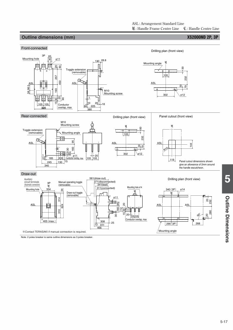
5-17
5
Ou
tline
Dim
ensio
ns
ASL : Arrangement Standard Line HL : Handle Frame Centre Line CL : Handle Centre Line
Outline dimensions (mm) XS2000ND 2P, 3P
90°
ø12
232
793030
105
302
3P
320320105 105
3065
38022560
20 1810
28.8130
340245
18510
160
95
20105 105
3030
302 ø12
105
7923
2
119
144
466371308
1325
160
9565
30
268
280
232
130
6530
3020
20
112
30
ø11
R10
ø11
15
314
105105
1520
2020
624
34334
310
405(max.)※
ASL
ASL
ASLASL
ASL
ASL
ASL
ASL
ø11
340(3P)
290(3P)
ø14
3P
LHLH
LH
LH
LHLH
450
9090
193
257
30 2015
20
250
5898
.5
1
1
ASL
LH
Draw-out
Front-connected
Rear-connected
Mounting angle
Mounting hole
M10 Mounting screw
M10 Mounting screw
Conductor overlap, max
Conductor overlap, max
Drilling plan (front view)
Toggle extension(removable)
Toggle extension(removable) Mounting angle
Drilling plan (front view) Panel cutout (front view)
Panel cutout dimensions shown give an allowance of 2mm around the handle escutcheon.
Mounting hole ø14
Conductor overlap, max
561(draw-out)
Draw-out toggle (removable)
Manual operating toggle (removable)
371(disconnected)341(test)
311(connected)Mounting hole
Mounting angle
Drilling plan (front view)
※Contact TERASAKI if manual connection is required.
Auxiliary circuit terminals (Automatic connection)
Note: 2 poles breaker is same outline dimensions as 3 poles breaker.
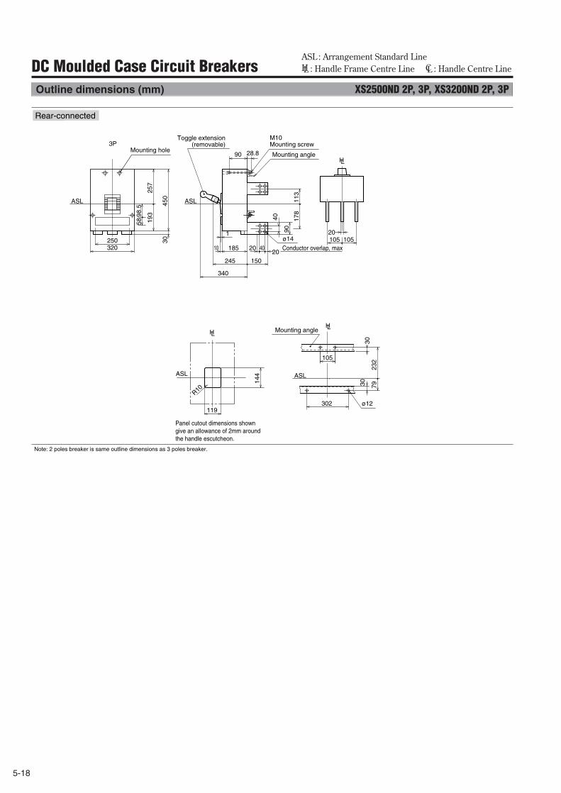
5-18
ASL : Arrangement Standard Line HL : Handle Frame Centre Line CL : Handle Centre LineDC Moulded Case Circuit Breakers
Outline dimensions (mm) XS2500ND 2P, 3P, XS3200ND 2P, 3P
ø14
ø12
450
30
257
19398
.558
232
793030
144
119
R10
105
302
113
178
90
40
320250
340
1
ASL ASL
ASL ASL
150245
105 10520
28.890
20 4020
18510
3P
LH
LHLH
裏面形Rear-connected
Mounting angle
Mounting angle
Mounting hole
M10 Mounting screw
Conductor overlap, max
Toggle extension(removable)
Panel cutout dimensions shown give an allowance of 2mm around the handle escutcheon.
Note: 2 poles breaker is same outline dimensions as 3 poles breaker.
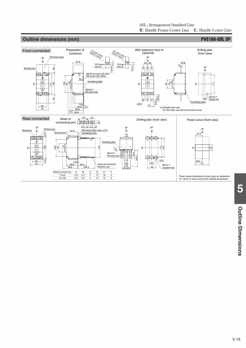
5-19
5
Ou
tline
Dim
ensio
ns
ASL : Arrangement Standard Line HL : Handle Frame Centre Line CL : Handle Centre Line
Outline dimensions (mm) PVE160-SDL 3P
CL CL
LH LHLH
Front-connected
Rear-connected Drilling plan (front view)
M4✕0.7Tapped hole
M4✕0.7Mounting screw
Panel cutout (front view)Detail of connecting part
Mounting plate (max. t3.2)
Studs are horizontaldirection only
Panel cutout dimensions shown give an allowance of 1.0mm or more around the handle escutcheon.
✽ Straight bars only. For line side, use with the terminal cover.
With extension bars ✽ (optional)
Drilling plan (front view)
Preparation of conductor
Insulating plate
Insulating plate
25
50
C D
E
A
3P
111
114
ø20
37.5
3P
38.577
B
C D
A
B
100.450.4
114
69.6
102
F
96.6
3P
6.1
25 25
100.
450.4
6.5(
max
.)
9(m
ax.)16.5(max.)
max.t514(max.)max.t5
ø5.5(25-40A)
ø9(63-160A)
ø5.5(25-40A)
ø9(63-160A)45
CL CL CL CLCL
LH LH
LH
25
7550
50
102
6.1
25.6
67.6
96.6
53.669.6
3P
10.5
3P
5050
130
111
3P
8.5
5.63
17
114
25 25
ø8.3
45
29.64
CL
LH
75
3P
5.3
5.3
130
67.6
22
22
1.6t
Insulating plate
Insulating plate
48
1.6t
M4✕0.7Tapped hole
Terminal cover
M4✕0.7Mounting screw
M5✕0.8 screw (25-40A)M8 screw (63-160A)
Terminal coverTerminal cover
Mounting hole
Mounting hole
Rated current (A) A B C D E25-40 10.5 6.5 4 13 16
63-160 12.5 8.5 4 13 16
F4
5
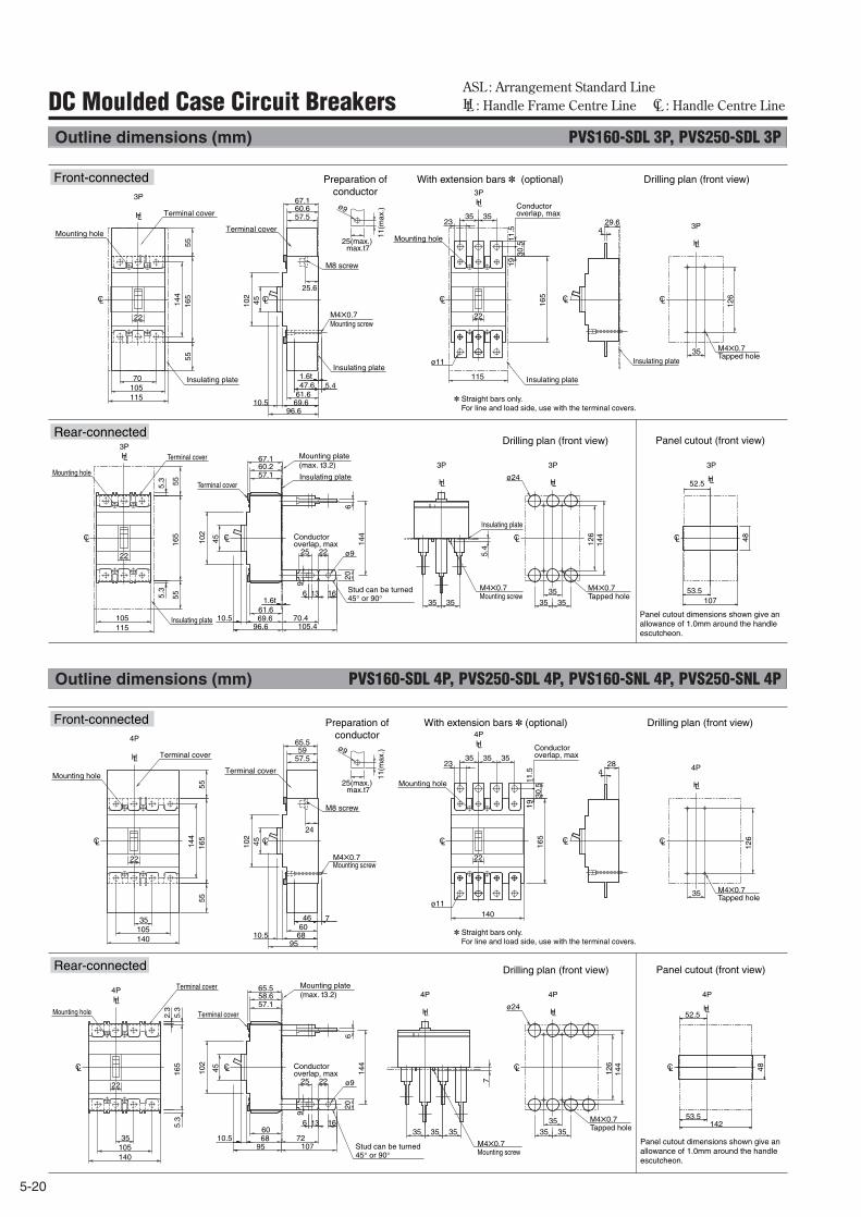
5-20
ASL : Arrangement Standard Line HL : Handle Frame Centre Line CL : Handle Centre LineDC Moulded Case Circuit Breakers
Outline dimensions (mm) PVS160-SDL 3P, PVS250-SDL 3P
CL CL CLCLCL
CL CL
LHLH
LH
CL
LH
LH
LH
CL
LH
5.4
23
3P 3P
3P
3P
ø24
3513
9
5.4
102
144
144
206
126
ø9
6 3516
69.661.6
70.496.6 105.4
3535 35
3P67.160.257.1
67.160.657.5
30.5
11.5
19
165
3535
102
5555
55
165
5516
514
4
45 126
35
25.6
47.61.6t
1.6t
10.5
10570
115
115
115
25 22
ø11
✽ Straight bars only. For line and load side, use with the terminal covers.96.6
69.610.561.6
29.64
22
3P
5.3
5.3
105
22
22
45
3P
Panel cutout dimensions shown give an allowance of 1.0mm around the handle escutcheon.
52.5
53.5107
48
Drilling plan (front view) Panel cutout (front view)
Preparation of conductor
With extension bars ✽ (optional) Drilling plan (front view) Front-connected
Rear-connected
Mounting hole
Insulating plate
Terminal cover
Insulating plate
M8 screw
Terminal cover
M4✕0.7Mounting screw
25(max.)max.t7
11(m
ax.)ø9
Insulating plate
Mounting hole
Conductoroverlap, max
Insulating plate
M4✕0.7Tapped hole
M4✕0.7Mounting screw
M4✕0.7Tapped hole
Insulating plate
Insulating plate
Mounting plate(max. t3.2)
Insulating plate
Stud can be turned 45° or 90°
Conductor overlap, max
Mounting hole
Terminal cover
Terminal cover
Outline dimensions (mm) PVS160-SDL 4P, PVS250-SDL 4P, PVS160-SNL 4P, PVS250-SNL 4P
CL CL CLCLCL
CL CL
LHLH
LH
CL
LH
LH
LH
CL
LH
7
23
4P 4P
4P
4P
ø24
3513
9
7
102
144
144
206
126
ø9
6 3516
6860
7295 107
3535 35 35
4P65.558.657.1
65.559
57.5
30.5
11.5
1916
5
35 3535
102
5555
165
165
144
45 126
35
24
46
10.5
10535
140
10535
140
140
25 22
ø11
✽ Straight bars only. For line and load side, use with the terminal covers.95
6810.560
284
22
4P
2.3
5.3
5.3
22
22
25(max.)max.t7
11(m
ax.)ø9
45
Drilling plan (front view) Panel cutout (front view)
Preparation of conductor
With extension bars ✽ (optional) Drilling plan (front view)
4P
52.5
48
14253.5
Panel cutout dimensions shown give an allowance of 1.0mm around the handle escutcheon.
Front-connected
Rear-connected
Mounting hole
Terminal cover
M8 screw
M4✕0.7
Terminal cover
Mounting screw
Mounting hole
Conductoroverlap, max
M4✕0.7Tapped hole
Mounting plate(max. t3.2)
M4✕0.7Mounting screw
Stud can be turned 45° or 90°
Conductor overlap, max
Mounting hole
Terminal cover
Terminal cover
M4✕0.7Tapped hole
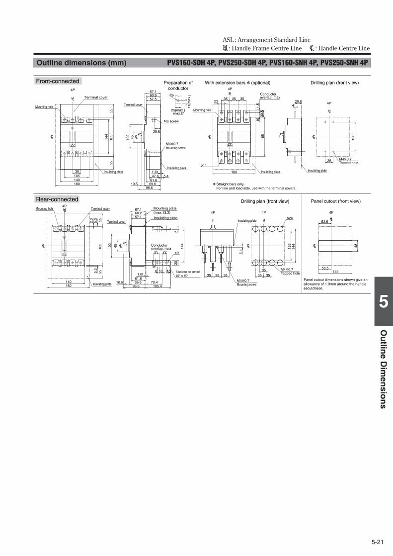
5-21
5
Ou
tline
Dim
ensio
ns
ASL : Arrangement Standard Line HL : Handle Frame Centre Line CL : Handle Centre Line
Outline dimensions (mm) PVS160-SDH 4P, PVS250-SDH 4P, PVS160-SNH 4P, PVS250-SNH 4P
CL CL CL
LH
CL
LH
LH
CL
LH
LH
LH
CL
LH
CL
CL
23
5.4
4P 4P
4P
3535 35
4P 4P
ø24
35
144
126
3535
30.5
11.5
1916
5
35 3535
5555
5555
165
165
144
126
35
10535
140180
140180
180
ø11
22
4P
2.3
5.3
5.3
22
22
4P
52.5
48
14253.5
Panel cutout dimensions shown give an allowance of 1.0mm around the handle escutcheon.
Drilling plan (front view) Panel cutout (front view)
Preparation of conductor
Drilling plan (front view)
67.160.657.5
102
4525.6
47.61.6t
96.669.610.561.6
29.64
13
9
102
144
206
ø9
6 16
69.661.6
70.496.6 105.4
67.160.257.1
1.6t
10.5
25 22
45
5.4
With extension bars ✽ (optional)
✽ Straight bars only. For line and load side, use with the terminal covers.
Front-connected
Rear-connected
Mounting hole
Terminal cover
Mounting hole
Conductoroverlap, max
M4✕0.7Tapped hole
M4✕0.7Mounting screw
Mounting hole Terminal cover
M4✕0.7Tapped hole
Insulating plate
Insulating plate
Insulating plateInsulating plate
M8 screw
Terminal cover
M4✕0.7Mounting screw
25(max.)max.t7
11(m
ax.)ø9
Insulating plate
Mounting plate(max. t3.2)
Insulating plate
Stud can be turned 45° or 90°
Conductor overlap, max
Terminal cover Insulating plate
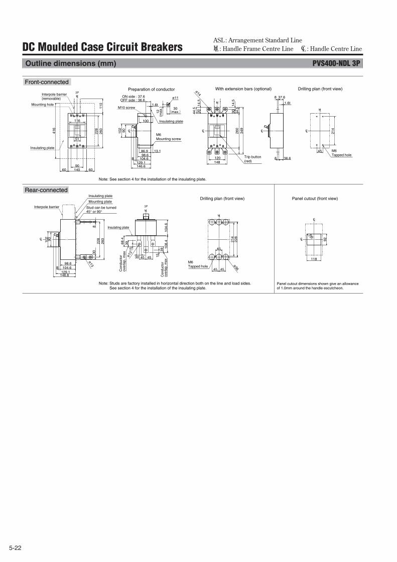
5-22
ASL : Arrangement Standard Line HL : Handle Frame Centre Line CL : Handle Centre LineDC Moulded Case Circuit Breakers
Outline dimensions (mm) PVS400-NDL 3P
CL CL
CL
CL CL CL CL
HL
L
HL
HL
HL
H
3P
3P
260
86.998.6
8
214
104.6
228
90102
116
13.1
110
45
90
51
129.1146.6
140
3014
.544
.530(max.)12
8
ø11
416
60 60
120148
14.5
30 44.5
349
260
118
92
R6
98.68
90102
104.6
228
260
830
ø13
129.1
30 45 45
108.
4
68.4
153915
39
214
45
228
45 45
ø36
104.
6
ø13
(max
.)
1.6t
37.68
1.6t
36.6
100
ø14
146.6
Front-connected
Rear-connected
Interpole barrier(removable)
Mounting hole
Insulating plate
Insulating plate
ON side : 37.6OFF side : 36.6
M10 screw
M6Mounting screw
M6Tapped hole
Con
duct
or
over
lap,
max
Con
duct
or
over
lap,
max
Stud can be turned 45° or 90°
M6Tapped hole
Mounting plate
Insulating plate
Insulating plate
Interpole barrier
Drilling plan (front view) Panel cutout (front view)
Preparation of conductor With extension bars (optional) Drilling plan (front view)
Panel cutout dimensions shown give an allowance of 1.0mm around the handle escutcheon.
Note: See section 4 for the installation of the insulating plate.
Note: Studs are factory installed in horizontal direction both on the line and load sides.See section 4 for the installation of the insulating plate.
Trip button (red)
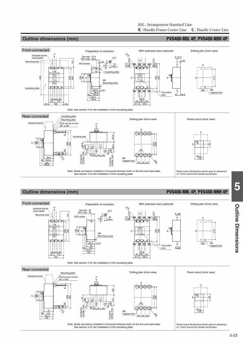
5-23
5
Ou
tline
Dim
ensio
ns
ASL : Arrangement Standard Line HL : Handle Frame Centre Line CL : Handle Centre Line
Outline dimensions (mm) PVS400-NDL 4P, PVS400-NDH 4P
CL CL
CL
CL CL CL CL
HL
L
HL
HL
HL
H
4P
4P
260
86.998.6
8
214
104.6
228
90102
116
13.1
110
45
45 4570 115
51
129.1146.645
185
3014
.544
.530(max.)12
ø14
8
ø11
420
60 6060 60 60
126.581.5
14.5
30 44.5
349
260
118
92
R6
36.598.68
90102
104.6
228
260
830
ø13
129.1
30 45 45 45
104.
610
8.4
68.4
153915
39
214
45
228
45 45 45
ø36ø1
3
(max
.)
52.5
1.6t
37.68
1.6t
36.6
100
146.6
Interpole barrier(removable)
Mounting hole
Insulating plate
Insulating plate
ON side : 37.6OFF side : 36.6
M10 screw
M6Mounting screw
Trip button (red)
M6Tapped hole
Con
duct
or
over
lap,
max
Con
duct
or
over
lap,
max
Stud can be turned 45° or 90°
Mounting plate
Insulating plate
Insulating plate
Interpole barrier
M6Tapped hole
Drilling plan (front view) Panel cutout (front view)
Preparation of conductor With extension bars (optional) Drilling plan (front view)
Panel cutout dimensions shown give an allowance of 1.0mm around the handle escutcheon.
Front-connected
Rear-connected
Note: See section 4 for the installation of the insulating plate.
Note: Studs are factory installed in horizontal direction both on the line and load sides.See section 4 for the installation of the insulating plate.
Outline dimensions (mm) PVS400-NNL 4P, PVS400-NNH 4P
CL CL
CL
CL CL CL CL
HL
L
HL
HL
HL
H
4P
4P
260
85.397
8
214
103
228
90102
116
14.7
110 368
45
45 4570 115
51
127.514545
185
3014
.544
.530(max.)12
ø14
358
ø11
60 60 60126.581.5
14.5
30 44.5
349
260
118
92
R6
36.5978
90102
103
228
260
830
ø13
127.5
30 45 45 45
103
11070
153915
39
214
45
228
45 45 45
ø36ø1
3
(max
.)
52.5
145
Front-connected
Rear-connected
Interpole barrier(removable)
Mounting hole
ON side : 36OFF side : 35
M10 screw
M6Mounting screw
Trip button (red)
M6Tapped hole
Con
duct
or
over
lap,
max
Con
duct
or
over
lap,
max
Stud can be turned 45° or 90°
Mounting plate
Interpole barrier
M6Tapped hole
Drilling plan (front view) Panel cutout (front view)
Preparation of conductor With extension bars (optional) Drilling plan (front view)
Note: See section 4 for the installation of the insulating plate.
Note: Studs are factory installed in horizontal direction both on the line and load sides.See section 4 for the installation of the insulating plate.
Panel cutout dimensions shown give an allowance of 1.0mm around the handle escutcheon.
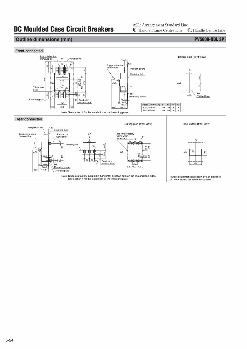
5-24
ASL : Arrangement Standard Line HL : Handle Frame Centre Line CL : Handle Centre LineDC Moulded Case Circuit Breakers
Outline dimensions (mm) PVS800-NDL 3P
HL
HLHL
HL
HL
ASLASL ASL
ASLASL ASL
172
92
104.6 8
146.6
70 70
13
70 70 43 43
117
1
26
10
120
.4 1
04.6
20
32
25
30.
5
80.5
117
126
R6ø
13
8
ø48
129.1
ø13
70
42
1.6t
29.6 11.4
1.6t
140
210 60 60
t2 L2
70
40
13
104.6
146.6 129.1
8
80
273
8
0
15
32 8
25
55.
5 4
6.5
110
513
160
80
117
1
26
141
1
32
80.5
170
51
90
t1 L1
29.6 11.4
L1
630 (400-630)
800 (500-800)
L2 t1
33.6 35.6 8
33.6 36.6 10
t2
8
10
3P
3P
Front-connected
Rear-connected
Interpole barrier(removable) Mounting hole
Toggle extension(removable)
Mounting hole
Insulating plate
Insulating plate
Insulating plate
Insulating plate
M8Mounting screw
M8Tapped hole
Trip button (red)
Conductor overlap, max
Rated Current (A)
Conductor overlap, max
Stud can be turned 90°
M8Tapped hole
Interpole barrier
M8Mounting screw
Mounting plate
ø15 for accessory wiring when necessary
Toggle extension(removable)
Drilling plan (front view) Panel cutout (front view)
Drilling plan (front view)
Panel cutout dimensions shown give an allowance of 1.0mm around the handle escutcheon.
Note: See section 4 for the installation of the insulating plate.
Note: Studs are factory installed in horizontal direction both on the line and load sides.See section 4 for the installation of the insulating plate.
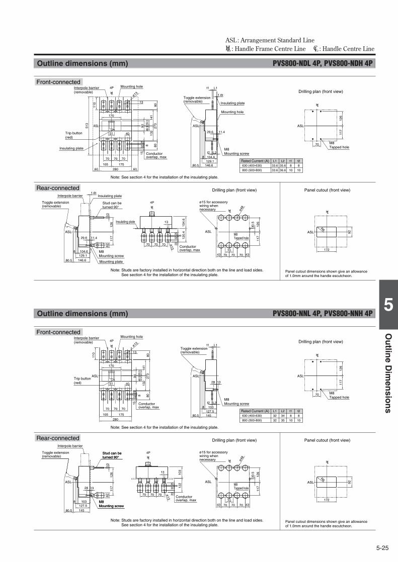
5-25
5
Ou
tline
Dim
ensio
ns
ASL : Arrangement Standard Line HL : Handle Frame Centre Line CL : Handle Centre Line
Outline dimensions (mm) PVS800-NDL 4P, PVS800-NDH 4P
HL
HLHL
HL
HL
ASLASL ASL
ASLASL ASL
172
92
104.6 8
146.6
70 70 70
13
70 70 70 43 43 1
17
126
10
120
.4
104
.6
20
32
25
30.
5
80.5
117
126
R6ø
13
8
ø48
129.1
ø13
70
42
1.6t
29.6 11.4
1.6t
70 70 70
105 175
280 60 60
t2 L2
70
40
13
104.6
146.6 129.1
8 8
0 2
73
80
15
32 8
25
55.
5 4
6.5
110
513
117
1
26
141
1
32
80.5
170
51
90
t1 L1
29.6 11.4
L1 L2 t1
33.6 35.6 8
33.6 36.6 10
t2
8
10
630 (400-630)
800 (500-800)
4P
4P
Interpole barrier(removable)
Mounting hole
Insulating plate
Trip button (red)
Conductor overlap, max
Mounting hole
Insulating plate
M8Mounting screw
Toggle extension(removable)
M8Tapped hole
Rated Current (A)
M8Mounting screw
Mounting plate
Insulating plate
Stud can be turned 90°
Interpole barrier
Toggle extension(removable)
Insulating plate
Conductor overlap, max
M8Tapped hole
ø15 for accessory wiring when necessary
Drilling plan (front view) Panel cutout (front view)
Drilling plan (front view)
Panel cutout dimensions shown give an allowance of 1.0mm around the handle escutcheon.
Note: See section 4 for the installation of the insulating plate.
Note: Studs are factory installed in horizontal direction both on the line and load sides.See section 4 for the installation of the insulating plate.
Front-connected
Rear-connected
Outline dimensions (mm) PVS800-NNL 4P, PVS800-NNH 4P
HL
HLHL
HL
HL
ASLASL ASL
ASLASL ASL
172
92
103
28 13
8
145
70 70 70
13
70 70 70 43 43
117
1
26
10
122
1
03
20
32
25
30.
5
80.5
117
126
R6
ø13
8
ø48
127.5
ø13
70
42
70 70 70
105 175
280
t2 L2
t1 L1
70
40
13
103
145
28 13
127.5 8
80
273
8
0
15
32 8
25
55.
5 4
6.5
110
117
1
26
141
1
32
80.5
170
51
90
L1 L2 t1
32 34 8
32 35 10
t2
8
10
630 (400-630)
800 (500-800)
4P
4P
Front-connected
Rear-connected
Interpole barrier(removable)
Mounting hole
Trip button (red)
Conductor overlap, max
M8Mounting screw
Toggle extension(removable)
Rated Current (A)
M8Tapped hole
Drilling plan (front view)
M8Mounting screw
Stud can be turned 90°
M8Mounting screw
Stud can be turned 90°
Toggle extension(removable)
Conductor overlap, max
M8Tapped hole
ø15 for accessory wiring when necessary
Drilling plan (front view) Panel cutout (front view)
Panel cutout dimensions shown give an allowance of 1.0mm around the handle escutcheon.
Note: Studs are factory installed in horizontal direction both on the line and load sides.See section 4 for the installation of the insulating plate.
Note: See section 4 for the installation of the insulating plate.
Interpole barrier
Air Circuit Breakers Moulded Case Circuit Breakers
Air Circuit Breakers Moulded Case Circuit BreakersDCDC
TERASAKI ELECTRIC CO., LTD.Head Office: 7-2-10 Hannancho, AbenokuOsaka, JapanCircuit Breaker Division: 7-2-10 Kamihigashi, Hiranoku Osaka, Japan
Telephone: 81-6-6791-9323Fax: 81-6-6791-9274Email: [email protected]
http://www.terasaki.co.jp/
TERASAKI ELECTRIC (M) SDN, BHD.Lot 3, Jalan 16/13D, 40000 Shah Alam, Selangor DarulEhsan, Malaysia
Telephone: 60-3-5549-3820Fax: 60-3-5549-3960Email: [email protected]
TERASAKI DO BRASIL LTDA.Rua Cordovil, 259-Parada De Lucas, 21250-450Rio De Janeiro-R.J., Brazil
Telephone: 55-21-3301-9898Fax: 55-21-3301-9861Email: [email protected]
http://www.terasaki.com.br
TERASAKI ELECTRIC (CHINA) LTD.72 Pacific Industrial Park, Xin Tang Zengcheng,Guangzhou 511340, China
Telephone: 86-20-8270-8556Fax: 86-20-8270-8586Email: [email protected]
TERASAKI ELECTRIC GROUP SHANGHAIREPRESENTATIVE OFFICERoom No. 1405-6, Tomson Commercial Building710 Dong Fang Road, Pudong, Shanghai, 200122, China
Telephone: 86-21-58201611Fax: 86-21-58201621Email: [email protected]
TERASAKI ELECTRIC (SHANGHAI) CO., LTD.Building 5 & 7, No.399 Xuanzhong Rd.Nanhui Industrial Zone, Shanghai, 201314, China
Telephone: 86-21-5818-6340Fax: 86-21-5818-6350Email: [email protected]
TERASAKI ELECTRIC (EUROPE) LTD.80 Beardmore Way, Clydebank Industrial EstateClydebank, Glasgow, G81 4HT, Scotland (UK)
Telephone: 44-141-941-1940Fax: 44-141-952-9246Email: [email protected]
http://www.terasaki.com/
TERASAKI ELECTRIC (EUROPE) LTD. FILIALE ITALIAVia Ambrosoli, 4A-20090 Rodano, Milano, Italy
Telephone: 39-02-92278300Fax: 39-02-92278320Email: [email protected]
http://www.terasaki.it/
TERASAKI ELECTRIC (EUROPE) LTD. SUCURSAL EN ESPAÑAPol. Ind. Coll de la Manya, C/Cal Ros dels Ocells 5-7,08403 Granollers, Barcelona, Spain
Telephone: 34-93-879-60-50Fax: 34-93-870-39-05Email: [email protected]
http://www.terasaki.es/
TERASAKI SKANDINAVISKA ABBox 2082 SE-128 22 Skarpnäck Sweden
Telephone: 46-8-556-282-30Fax: 46-8-556-282-39Email: [email protected]
http://www.terasaki.se/
TERASAKI CIRCUIT BREAKERS (S) PTE. LTD.17 Tuas Street Singapore 638454
Telephone: 65-6744-9752Fax: 65-6748-7592Email: [email protected]
Ratings and specifications are subject to change without notice.
CAT REF. ’14-I73E