installation and technical manual for the issue 1 isa100 ......ning, configuring, adminstering, and...
TRANSCRIPT

m WARNINGPERSONAL INJURYDO NOT USE these products as safety or emergency stop devices or in any other application where failure of the product could result in personal injury.
Failure to comply with these instructions could result in death or serious injury.
Installation and Technical Manual for theISA100 Wireless Pressure Sensor, WPS Series
Sensing and Productivity Solutions
Issue 1
50095583
m WARNINGHoneywell does not recommend using devices for critical control applications where there is, or may be, a single point of failure or where single points of failure may result in an unsafe condition. It is up to the end-user to weigh the risks and benefits to determine if the products are appropriate for the application based on security, safety and performance. Additionally, it is up to the end-user to ensure that the control strategy results in a safe operating condition if any crucial segment of the control solution fails. Honeywell customers assume full responsibility for learning and meeting the required Declaration of Conformity, Regulations, Guidelines, etc. for each country in their distribution market.
m WARNINGRF EXPOSURETo satisfy FCC RF exposure requirements for mobile transmitting devices, a separation distance of 20 cm [7.87 in] or more should be maintained between the antenna of this device and persons during device operation To ensure compliance, operation at closer than this distance is not recommended. The antenna used for this transmission must not be co-located in conjunction with any other antenna or transmitter.
Failure to comply with these instructions could result in death or serious injury.
m WARNINGThe WPS must be installed in accordance with the requirements specified in this document in order to comply with the specific Country Communication Agency requirements (i.e., FCC, IC, ETSI, ACMA, etc.). See Section 6.1 as this requires choosing the correct Country Use Code and thus allowable antenna and/or cable usage.
Intended AudienceThis guide is intended for people who are responsible for plan-ning, configuring, adminstering, and operating the ISA100 Wire-less™ Network.
Prerequisite SkillsIt is assumed that you are familiar with the operation of ISA100 Wireless™ Networks.
About this DocumentThis document outlines professional installation requirements for the ISA100 Wireless Pressure Sensor, WPS Series. Professional installation is required to comply with certification agency and legal requirements. This document must be adhered to for all installations of the Honeywell ISA100 Wireless Pressure Sensor, WPS Series.
These devices are not intended for critical control where there is a single point of failure or where single points of failure result in unsafe conditions. As with any process control solution, it is the end users’ responsibility to weigh the risks and benefits to deter-mine if the products used are the right match for the application based on security, safety, regulations, and performance.
Revision Information
Document name Document ID Publication Date
Installation and Technical Manual for the ISA100 WPS Series Wireless Pressure Sensor
50095583 March 2015
New 50095583, Issue 1
March 2015
ReferencesThe following list identifies all documents that may be sources of reference for material discussed in this publication.
Document title Document No.
OneWireless™ Network Planning and Installation Guide
OWDOC-X253
OneWireless™ Wireless Device Manager User's Guide
OWDOC-X254
OneWireless™ Field Device Access Point User’s Guide
OWDOC-X256

2 sensing.honeywell.com
Installation and Technical Manual for the ISA100 Wireless Pressure Sensor, WPS Series
ISSUE 1 50095583
TABLE OF CONTENTS
1 INTRODUCTION. . . . . . . . . . . . . . . . . . . . . .1 1.1 Purpose . . . . . . . . . . . . . . . . . . . . . . . . . . . . 1 1.2 Scope . . . . . . . . . . . . . . . . . . . . . . . . . . . . . . 1 1.3 ISA100 Wireless™ Network Overview . . . . . 1 1.4 About the Sensor . . . . . . . . . . . . . . . . . . . . . 1 1.4.1 Power . . . . . . . . . . . . . . . . . . . . . . . . . . . 1 1.4.2 Input . . . . . . . . . . . . . . . . . . . . . . . . . . . . 1 1.4.3 Product Nomenclature . . . . . . . . . . . . . . 2 1.5 Preface . . . . . . . . . . . . . . . . . . . . . . . . . . . . . 2 1.6 Site Survey . . . . . . . . . . . . . . . . . . . . . . . . . . 2 1.7 Abbreviations and Definitions. . . . . . . . . . . . 3
2 SPECIFICATIONS, CERTIFICATIONS, AND APPROVALS . . . . . . . . . . . . . . . . . . . .4 2.1 Approvals and Ratings . . . . . . . . . . . . . . . . . 4 2.2 Radio Module Specifications . . . . . . . . . . . . 4 2.3 Battery Specifications. . . . . . . . . . . . . . . . . . 5 2.4 EMC Specifications . . . . . . . . . . . . . . . . . . . 5 2.5 General Specifications . . . . . . . . . . . . . . . . . 5 2.6 ISA100 Wireless Pressure Sensor, WPS Series Power Specifications. . . . . . . . . 6 2.7 Weight. . . . . . . . . . . . . . . . . . . . . . . . . . . . . . 6 2.8 Antenna Connection . . . . . . . . . . . . . . . . . . . 6 2.9 Certifications and Approvals . . . . . . . . . . . . 6 2.9.1 FCC Compliance Statements . . . . . . . . . 6 2.9.2 IC Compliance Statements. . . . . . . . . . . 6 2.9.3 RF Safety Statements . . . . . . . . . . . . . . . 6 2.10 Declaration of Conformity. . . . . . . . . . . . . . . 7 2.11 Intended Country Usage . . . . . . . . . . . . . . . 8
3 GENERAL DESCRIPTION . . . . . . . . . . . . . .9 3.1 Intended Use . . . . . . . . . . . . . . . . . . . . . . . . 9 3.2 WPS Series Sensor Diagrams . . . . . . . . . . . 9 3.3 Process Connection . . . . . . . . . . . . . . . . . . . 9 3.4 WPS Series Sensor Location . . . . . . . . . . . . 9 3.5 Conduit/Cable Entries. . . . . . . . . . . . . . . . . . 9 3.6 Bracket Mounting . . . . . . . . . . . . . . . . . . . . . 9 3.7 Pressure Port . . . . . . . . . . . . . . . . . . . . . . . . 9 3.8 Dimensions . . . . . . . . . . . . . . . . . . . . . . . . . 10
4 PROCESS INSERTION . . . . . . . . . . . . . . . 11 4.1 Pressure Sensing . . . . . . . . . . . . . . . . . . . . 11 4.1.1 Piping . . . . . . . . . . . . . . . . . . . . . . . . . . 11 4.1.2 Process Connections . . . . . . . . . . . . . . 11 4.1.3 General Piping Guidelines . . . . . . . . . . 12 4.1.4 Sensor Housing Swiveling . . . . . . . . . . 12
5 CABLES . . . . . . . . . . . . . . . . . . . . . . . . . .13 5.1 WPS Series Sensor Cables. . . . . . . . . . . . . 13 5.2 Protection of Antenna Connections . . . . . . 14
6 APPROVED ANTENNA TYPES/GAINS . . .15 6.1 Antenna Details . . . . . . . . . . . . . . . . . . . . . 15 6.2 Omni-directional Antenna Design . . . . . . . 17 7 ANTENNA ADJUSTMENT & MOUNTING 18 7.1 Requirements . . . . . . . . . . . . . . . . . . . . . . . 18 7.1.1 Radio Installation Requirements. . . . . . 18 7.2 Direct Mount Antenna. . . . . . . . . . . . . . . . . 18 7.2.1 Direct Mount, General Guidelines . . . . 18 7.2.2 Direct Mount, Straight. . . . . . . . . . . . . . 18 7.3 Remote Antennas . . . . . . . . . . . . . . . . . . . . 18 7.3.1 Outdoor Installation Warnings . . . . . . . 18 7.3.2 Cable Requirement. . . . . . . . . . . . . . . . 19 7.3.3 Lightning Arrestor . . . . . . . . . . . . . . . . . 19 7.3.4 Choosing a Mounting Location . . . . . . 19 7.3.5 Site Location. . . . . . . . . . . . . . . . . . . . . 20 7.3.6 Antenna Mount Types. . . . . . . . . . . . . . 20 7.3.7 Magnetic Mounting. . . . . . . . . . . . . . . . 20 7.3.8 Adhesive Mounting. . . . . . . . . . . . . . . . 21 7.3.9 Mast Mounting . . . . . . . . . . . . . . . . . . . 21 7.3.10 Grounding the Antenna . . . . . . . . . . . . 23 7.3.11 Connection Diagrams for Remote Antenna Configuration . . . . . . 24 7.4 Antenna Mounting Considerations . . . . . . . 24 7.4.1 Antenna Mounting Location with Respect to RF Signal . . . . . . . . . . . . . . 24 7.4.2 Antenna Mounting Location with Respect to Antenna Location . . . . . . . . 25 7.4.3 Line-of-Sight Considerations . . . . . . . . 25 7.5 RF Interference Considerations . . . . . . . . . 26 7.5.1 General. . . . . . . . . . . . . . . . . . . . . . . . . 26 7.5.2 WiFi Networks. . . . . . . . . . . . . . . . . . . . 26 7.5.3 Smart Phone “Apps”. . . . . . . . . . . . . . . 26 7.5.4 Bluetooth® Devices. . . . . . . . . . . . . . . . 26 7.5.5 Wireless Video Camera & Video Links . 26 7.5.6 Microwave Ovens. . . . . . . . . . . . . . . . . 27 7.5.7 Cordless Phones/Baby Monitors . . . . . 27 7.6 Wireless Link Quality Measurements . . . . . 27 7.6.1 Link Measurements . . . . . . . . . . . . . . . 27 7.6.2 Connection Quality Labels . . . . . . . . . . 27

Honeywell Sensing and Productivity Solutions i
Installation and Technical Manual for the ISA100 Wireless Pressure Sensor, WPS Series
ISSUE 1 50095583
8 EQUIVALENT ISOTROPICALLY RADIATED POWER (EIRP). . . . . . . . . . . . . . . . . . . . . .28 8.1 EIRP Limits and TX Power Setting . . . . . . . 28
9 OPERATING ONEWIRELESS™ USER INTERFACE. . . . . . . . . . . . . . . . . . .29 9.1 Overview of the OneWireless™ User Interface. . . . . . . . . . . . . . . . . . . . . . . 29 9.2 Provisioning the OneWireless™ User Interface. . . . . . . . . . . . . . . . . . . . . . . 29 9.3 Channel Activation on the WPS Sensor . . . 31 9.4 Setting TX Power . . . . . . . . . . . . . . . . . . . . 32 9.4.1 TX Power Setting Policy . . . . . . . . . . . . 32 9.4.2 Power Setting Procedure . . . . . . . . . . . 32 9.5 Reading Battery Voltage. . . . . . . . . . . . . . . 32 9.5.1 Reading Sensor Battery Voltage . . . . . 32 9.6 Restore to Factory Defaults . . . . . . . . . . . . 33 9.7 Calibrating the Sensor . . . . . . . . . . . . . . . . 33
10 FUNCTION BLOCKS . . . . . . . . . . . . . . . . .33 10.1 Introduction. . . . . . . . . . . . . . . . . . . . . . . . . 33 10.1.1 Configuration . . . . . . . . . . . . . . . . . . . . 33 10.2 Data Block Description. . . . . . . . . . . . . . . . 33 10.2.1 Data Block Types . . . . . . . . . . . . . . . . . 33 10.3 Hardware Description. . . . . . . . . . . . . . . . . 34 10.3.1 Detailed Block Diagram . . . . . . . . . . . . 34 10.3.2 Sensor Module . . . . . . . . . . . . . . . . . . . 34 10.3.3 Interface Board. . . . . . . . . . . . . . . . . . . 34 10.3.4 Radio Board . . . . . . . . . . . . . . . . . . . . . 34 10.3.5 LCD Display . . . . . . . . . . . . . . . . . . . . . 34 10.3.6 Battery . . . . . . . . . . . . . . . . . . . . . . . . . 34 10.3.7 Battery Life . . . . . . . . . . . . . . . . . . . . . . 34
11 OPERATION . . . . . . . . . . . . . . . . . . . . . . .35 11.1 Overview. . . . . . . . . . . . . . . . . . . . . . . . . . . 35 11.1.1 Display Modes . . . . . . . . . . . . . . . . . . . 35 11.2 Sensor PV Display . . . . . . . . . . . . . . . . . . . 35 11.3 Battery Considerations . . . . . . . . . . . . . . . . 36 11.4 Battery Life Remaining . . . . . . . . . . . . . . . . 37 11.5 Other User Settings . . . . . . . . . . . . . . . . . . 37
12 MAINTENANCE & REPAIR . . . . . . . . . . . .37 12.1 Parts . . . . . . . . . . . . . . . . . . . . . . . . . . . . . . 37 12.2 Replacing Batteries . . . . . . . . . . . . . . . . . . 37 12.2.1 When to Replace . . . . . . . . . . . . . . . . . 37 12.2.2 Battery Storage. . . . . . . . . . . . . . . . . . . 38 12.2.3 Transporting Batteries . . . . . . . . . . . . . 38 12.2.4 Tools Required . . . . . . . . . . . . . . . . . . . 38 12.3 Replacing Antenna and Radome . . . . . . . . 39 12.3.1 Tools Required . . . . . . . . . . . . . . . . . . . 39 12.4 Software Updates . . . . . . . . . . . . . . . . . . . . 40 12.5 Battery Readings . . . . . . . . . . . . . . . . . . . . 40 12.5.1 Reading Estimated Battery Life Remaining . . . . . . . . . . . . . . . . . . . 40 12.5.2 Reading Sensor Internal Temperature . . . . . . . . . . . . . . . . . . . . . 40 12.6 WPS Reading . . . . . . . . . . . . . . . . . . . . . . . 40 12.6.1 WPS Device Identification . . . . . . . . . . 40 12.6.2 Reading Sensor Process Variable . . . . 41 12.6.3 Reading Sensor Pressure Limits . . . . . 41 12.7 Setting Measurement Units . . . . . . . . . . . . 41 12.8 Setting Range. . . . . . . . . . . . . . . . . . . . . . . 42 12.9 Setting “Scaling”. . . . . . . . . . . . . . . . . . . . . 42 12.10 Setting Periodic Update Interval. . . . . . . . . 42 12.11 Setting LCD Display Options . . . . . . . . . . . 43
13 FAULT CODE & LINK STATUS INFO . . . .43
14 AGENCY LABEL INFORMATION . . . . . . .43

ii sensing.honeywell.com
Installation and Technical Manual for the ISA100 Wireless Pressure Sensor, WPS Series
ISSUE 1 50095583
List of FiguresFigure 1. ISA100 Wireless Pressure Sensor Nomenclature . . . 2Figure 2. WPS Functional Diagram . . . . . . . . . . . . . . . . . . . . . . 3Figure 3. WPS Series Sensor with Radome . . . . . . . . . . . . . . . 9Figure 4. Dimensions . . . . . . . . . . . . . . . . . . . . . . . . . . . . . . . 10Figure 5. Typical Arrangement for 1/2 NPT Piping . . . . . . . . . 11Figure 6. Process Connection - Pipe Fitting . . . . . . . . . . . . . . 11Figure 7. WPS Antenna Extender Cables . . . . . . . . . . . . . . . . 13Figure 8. WPS Antenna Extender Cable Mounting Hole . . . . 14Figure 9. Application of Protective Tape . . . . . . . . . . . . . . . . . 14Figure 10. Radiation Pattern of Omni-Directional Antenna . . . . 17Figure 11. Direct Mount Antenna . . . . . . . . . . . . . . . . . . . . . . . 18Figure 12. Magnetic Mount Antenna . . . . . . . . . . . . . . . . . . . . 20Figure 13. Adhesive Mounting Steps . . . . . . . . . . . . . . . . . . . . 21Figure 14. WPS Connected to Remote Antenna, Remotely . . . 24Figure 15. WPS Connected Via Lightning Arrestor . . . . . . . . . 24Figure 16. WPS to FDAP Free of Obstacles . . . . . . . . . . . . . . . 25Figure 17. WPS to FDAP Affected by Obstacles . . . . . . . . . . . 25Figure 18. RF Link Quality Data Block . . . . . . . . . . . . . . . . . . . 27Figure 19. OneWireless™ User Interface Screen . . . . . . . . . . . 29Figure 20. Tag Name . . . . . . . . . . . . . . . . . . . . . . . . . . . . . . . . 29Figure 21. Enable for 60 Minutes Button . . . . . . . . . . . . . . . . . 29Figure 22. Tag Name Pop-up Box . . . . . . . . . . . . . . . . . . . . . . 30Figure 23. Accept Button on Ribbon Bar . . . . . . . . . . . . . . . . . 30Figure 24. Accept Button Pop-up Window . . . . . . . . . . . . . . . . 30Figure 25. Select WPS in Selection Panel . . . . . . . . . . . . . . . . 30Figure 26. Tag Name Field Entry . . . . . . . . . . . . . . . . . . . . . . . 30Figure 27. Select Channel on Selection Panel . . . . . . . . . . . . . 31Figure 28. Activate Button on Ribbon Bar . . . . . . . . . . . . . . . . 31Figure 29. Pop-up Window . . . . . . . . . . . . . . . . . . . . . . . . . . . . 31Figure 30. Channel Icon . . . . . . . . . . . . . . . . . . . . . . . . . . . . . . 31Figure 31. Channel Information on Property Panel. . . . . . . . . . 31Figure 32. RF Power Setting Procedure . . . . . . . . . . . . . . . . . . 32Figure 33. Battery Voltage . . . . . . . . . . . . . . . . . . . . . . . . . . . . 32Figure 34. Location of Reset Button . . . . . . . . . . . . . . . . . . . . . 33Figure 35. Battery Insulator Tab Location . . . . . . . . . . . . . . . . . 36Figure 36. Battery Estimates. . . . . . . . . . . . . . . . . . . . . . . . . . . 37Figure 37. Sensor Battery Replacement. . . . . . . . . . . . . . . . . . 38Figure 38. Antenna Replacement . . . . . . . . . . . . . . . . . . . . . . . 39Figure 39. Sensor Battery Estimates . . . . . . . . . . . . . . . . . . . . 40Figure 40. Sensor Internal Temperature . . . . . . . . . . . . . . . . . . 40Figure 41. Field Device Summary Dialog Box . . . . . . . . . . . . . 41Figure 42. Channel Name . . . . . . . . . . . . . . . . . . . . . . . . . . . . . 41Figure 43. Process Variable . . . . . . . . . . . . . . . . . . . . . . . . . . . 41Figure 44. Sensor Name . . . . . . . . . . . . . . . . . . . . . . . . . . . . . . 41Figure 45. Sensor Pressure Limits . . . . . . . . . . . . . . . . . . . . . . 41Figure 46. Scaling Dialog Box . . . . . . . . . . . . . . . . . . . . . . . . . 42Figure 47. Input Publication Rate Dialog Box . . . . . . . . . . . . . . 42Figure 48. LCD Display Timing . . . . . . . . . . . . . . . . . . . . . . . . . 43
List of TablesTable 1. Table Symbol Definitions . . . . . . . . . . . . . . . . . . . . . . iiiTable 2. Pressure Range Conversion Chart . . . . . . . . . . . . . . 2Table 3. Abbreviations and Definitions . . . . . . . . . . . . . . . . . . 3Table 4. Approvals and Ratings . . . . . . . . . . . . . . . . . . . . . . . 4Table 5. Radio Module Specifications . . . . . . . . . . . . . . . . . . . 4Table 6. Radio Certifications . . . . . . . . . . . . . . . . . . . . . . . . . . 4Table 7. Battery Specifications . . . . . . . . . . . . . . . . . . . . . . . . 5Table 8. Environmental Specifications . . . . . . . . . . . . . . . . . . 5Table 9. Sensor Specifications . . . . . . . . . . . . . . . . . . . . . . . . 5Table 10. Intended County Use - North America . . . . . . . . . . . 8Table 11. Intended Country Use - European Union . . . . . . . . . 8Table 12. WPS Series Recommended Locations . . . . . . . . . . . 9Table 13. Sensor to Antenna Cable Specifications . . . . . . . . . 13Table 14. Antenna Options - Country Code A. . . . . . . . . . . . . 15Table 15. Antenna Options - Country Code B. . . . . . . . . . . . . 16Table 16. WPS Standard Antenna Options . . . . . . . . . . . . . . . 16Table 17. WPS Connection Quality Labels . . . . . . . . . . . . . . . 27Table 18. EIRP Limits and Radio TX Power Setting . . . . . . . . 28Table 19. Block Types . . . . . . . . . . . . . . . . . . . . . . . . . . . . . . . 33Table 20. PV Display . . . . . . . . . . . . . . . . . . . . . . . . . . . . . . . . 35Table 21. PV Engineering Units . . . . . . . . . . . . . . . . . . . . . . . . 35Table 22. Sensor Link Status Display . . . . . . . . . . . . . . . . . . . 35Table 23. Sensor Error Codes . . . . . . . . . . . . . . . . . . . . . . . . . 36Table 24. WPS Replacement Parts . . . . . . . . . . . . . . . . . . . . . 37Table 25. Battery Replacement Procedure . . . . . . . . . . . . . . . 39

Honeywell Sensing and Productivity Solutions iii
Installation and Technical Manual for the ISA100 Wireless Pressure Sensor, WPS Series
ISSUE 1 50095583
Symbol Definitions
The following table lists those symbols used in this document to denote certain conditions.
Table 1 – Table Symbol Definitions
Symbol Definition
, ATTENTION: Identifies information that requires special consideration.
TIP: Identifies advice or hints for the user, often in terms of performing a task.
CAUTION Indicates a situation which, if not avoided, may result in equipment or work (data) on the system being damaged or lost, or may result in the inability to properly operate the process.
m CAUTION: Indicates a potentially hazardous situation which, if not avoided, may result in minor or moderate injury. It may also be used to alert against unsafe practices.
m CAUTION symbol on the equipment refers the user to the product manual for additional infor-mation. The symbol appears next to required information in the manual.
m WARNING: Indicates a potentially hazardous situation, which, if not avoided, could result in serious injury or death.
m WARNING symbol on the equipment refers the user to the product manual for additional infor-mation. The symbol appears next to required information in the manual.
WARNING, Risk of electrical shock: Potential shock hazard where HAZARDOUS LIVE volt-ages greater than 30 Vrms, 42.4 Vpeak, or 60 Vdc may be accessible.
ESD HAZARD: Danger of an electro-static discharge to which equipment may be sensitive. Observe precautions for handling electrostatic sensitive devices.
Protective Earth (PE) terminal: Provided for connection of the protective earth (green or green/yellow) supply system conductor.
Functional earth terminal: Used for non-safety purposes such as noise immunity improve-ment. NOTE: This connection shall be bonded to Protective Earth at the source of supply in accordance with national local electrical code requirements.
Earth Ground: Functional earth connection. NOTE: This connection shall be bonded to Protec-tive Earth at the source of supply in accordance with national and local electrical code require-ments.
Chassis Ground: Identifies a connection to the chassis or frame of the equipment shall be bonded to Protective Earth at the source of supply in accordance with national and local electri-cal code requirements.
The ISA100 Wireless Compliant logo indicates the device has received ISA100.11a conformance certifi-cation and is registered with the Wireless Compliance Institute, assuring device interoperability.
C-Tick Mark. The C-Tick Mark is a certification trade mark registered to ACMA (Australian Com-munications and Media Authority) in Australia under the Trade Marks Act 1995 and to RSM in New Zealand under section 47 of the NZ Trade Marks Act. The mark is only to be used in accor-dance with conditions laid down by ACMA and RSM. This mark is equal to the CE Mark used in the European Union.
Notified Body. For radio equipment used in the European Union in accordance with the R&TTE Directive, the CE Mark and the notified body (NB) identification number is used when the NB is involved in the conformity assessment procedure.

iv sensing.honeywell.com
Installation and Technical Manual for the ISA100 Wireless Pressure Sensor, WPS Series
ISSUE 1 50095583

Honeywell Sensing and Productivity Solutions 1
Installation and Technical Manual for the ISA100 Wireless Pressure Sensor, WPS Series
ISSUE 1 50095583
1 INTRODUCTION
1.1 PurposeThis document describes the Honeywell ISA100 Wireless Pressure Sensor, WPS Series’ function, operation, and maintenance.
1.2 ScopeThe document includes:
• Details of topics that relate uniquely to the Honeywell ISA100 Wireless Pressure Sensor, WPS Series
• Installation and mounting
1.3 ISA100 Wireless™ Network OverviewISA100 Wireless™ Network is an all-digital, serial, two-way communication mesh network that interconnects industrial field sensors to a central system.
ISA100.11a Network has defined standards to which field devices and operator stations communicate with each another. The communications protocol is built as an “open system” to allow all field devices and equipment that are built to ISA100 Wireless™ standards to be integrated into a system, regardless of the device manufacturer. This interoperability of devices using ISA100 Wireless™ technology is to become an industry standard for automation systems.
1.4 About the SensorThe ISA100 Wireless Pressure Sensor, WPS Series is furnished with an ISA100-compliant wireless interface to operate in a compatible distributed ISA100 wireless system. The sensor will interoperate with any ISA100 wireless network.
The sensor includes ISA100-compliant electronics for operating in a 2.4 GHz wireless network.
1.4.1 PowerThe sensor is powered by two each, D-sized Lithium Thionyl Chloride cells. Battery life is estimated to be five years at 5 second update interval; subject to vary depending on user setting of update interval. There is no external power available for this sensor.
1.4.2 InputThe sensor supports one input channel. This channel is available as either:
• Gage pressure
• Absolute pressure
The sensor measures this analog pressure and transmits a digital output signal proportional to the measured value. See Figure 2 for the functional diagram.

2 sensing.honeywell.com
Installation and Technical Manual for the ISA100 Wireless Pressure Sensor, WPS Series
ISSUE 1 50095583
1.4.3 Product NomenclatureThis document is valid for the ISA100 Wireless Pressure Sensor, WPS Series in the following variations:
Figure 1. ISA100 Wireless Pressure Sensor, WPS Series Nomenclature
A US, Canada,Mexico
WPS
Type
A
Country Use Code
A US, Canada,Australia
GP
MeasurandType
WPS SeriesWirelessPressureSensor
1
Gen Code
B
RF Code
1 Version 1 B 2.4 GHz, ISA100.11a
12
12
00 No antenna; RP-SMA jack
2.0 dBi omni antenna
Antenna Type Code
AP Absolute pressure
GP Gagepressure
1
ConnectionType
1 1/2 in NPTmale
2 3/4 in NPTmale
PD
Measurand Range(refer to measurand range chart)
D
E
F
G
H
J
1
Display
0 NoLCD
N
Protection
K
1 withLCD
Specials
P
B
K
P
EnclosureType
P Plastic
1/4 in NPT femaleconnection is
integral to 1/2 in NPT male and
3/4 in NPT maleconnections.
BAll otherapprovedcountries
N Not intrinsicallysafe
For “A” coded versions,refer to Limitless™ WPS P2P datasheet, 32305926.
Table 2. Pressure Range Conversion Chart
Unit Code DescriptionPressure Range
D E F G H J KP psi 0 to 50 0 to 200 0 to 500 0 to 1000 0 to 1500 0 to 5000 0 to 10000B bar 0 to 3.45 0 to 13.8 0 to 34.5 0 to 68.9 0 to 103.4 0 to 344.7 0 to 689.5K kPa 0 to 344.7 0 to 1379 0 to 3447.4 0 to 6894.7 0 to 10342 0 to 34473 0 to 68947
1.5 PrefaceThis manual covers professional installation of the Honeywell ISA100 Wireless Pressure Sensor, WPS Series. The WPS Series is classified by the FCC as a device that must be professionally installed. To be in compliance with FCC requirements, the radio must be installed with one of the approved antennas listed in this document.
1.6 Site SurveyIt is assumed for the purposes of this document that a site survey has been performed and that the antenna types, cable lengths and lightning surge arrestors were appropriately selected per the results of that survey. Any changes to these items as a result of the actual installation of the WPS Series sensors into the site may require that the TX power setting of the radio board needs to be adjusted from the factory setting in order to maintain agency approvals. See Sections 8 and 9 for more information.

Honeywell Sensing and Productivity Solutions 3
Installation and Technical Manual for the ISA100 Wireless Pressure Sensor, WPS Series
ISSUE 1 50095583
Figure 2. WPS Functional Diagram
Gage or AbsolutePressure Sensor
LCDDisplay
Power Source(battery)
Microcontroller
Sensor SignalCond. Circuit
Interface Board
Radio Board
Microcontroller
2.4 GHzRadio
RF AnalogFront-End
EEPROM
Ante
nna
Pressure Input
1.7 Abbreviations and DefinitionsTable 3. Table of Abbreviations and DefinitionsACMA Australian Communications and Media Authority
AD Authentication Device
ANATEL National Agency of Telecomnunication (Agência Nacional de Telecomunicaçõe)
AWG American Wire Gauge
Co-located Two or more radios transmitting simultaneously and with less than 20 cm [7.87 in] of separation distance.
CSA Canadian Standards Association
DCS Distributed Control System
DSSS Direct Sequence Spread Spectrum
EMC Electromagnetic Compatibility
ETSI European Telecommunications Standards Insti-tute
EU European Union
FCC Federal Communications Committee
FHSS Frequency-Hopping Spread Spectrum
FSK Frequency Shift Keying
GFSK Gaussian Frequency Shift Keying
GTS Honeywell Global Technical Services
IC Industry Canada
IEEE Institute of Electrical and Electronics Engineers
ISA100 International Society of Automation open-stan-dard wireless networking technology
LR-WPAN Low Rate Wireless Personal Area Network
MPE Maximum Permissible Exposure
MSG Honeywell Model Selection Guide
NA North America – United States of America and Canada
NEMA National Electrical Manufacturers Association
OQPSK Offset Quadrature Phase-Shift Keying
PER Packet Error Rate - a measurement of data not received correctly (may be caused by interfer-ence or very low signal levels)
R.F. Radio Frequency
RP-SMA Reverse-Polarity SubMiniature version A (used for wireless antennas)
SNR Signal to Noise Ratio - a measurement of signal received
TX Transmit
WDM Wireless Device Manager
Wi-Fi Wireless Local Area Network based on IEEE 802.11 Specifications
WLAN Wireless Local Area Network (aka WIFI)
WNSIA Wireless Network for Secure Industrial Applica-tion

4 sensing.honeywell.com
Installation and Technical Manual for the ISA100 Wireless Pressure Sensor, WPS Series
ISSUE 1 50095583
2 SPECIFICATIONS, CERTIFICATIONS, AND APPROVALS
2.1 Approvals and RatingsSee the product label for applicable approvals and ratings.
Table 4. Approvals and Ratings
Approval/Item Ratings/Description
Enclosure type IP65, IP67
Communication agencyapprovals and standards
16 dBm: FCC Part 15.247 and 15.209; Industry Canada RSS 210 Issue 8; ACMA C-tick mark8 dBm: ETSI EN 300 328 V1.8.1; CE mark
2.2 Radio Module Specifications
Table 5. Radio Module Specifications
Item Specification
Radio module Honeywell RF-PCBa
Wireless standard IEEE Standard: 802.15.4, 2.4 GHz global, license-free bandsProtocol: ISA100.11a
Data rate 250 kbps
Operating frequency ISM 2.4 GHz
Module transmit power (max.) Country code A: 16 dBm max; Country code B: 8 dBm max.
Receive sensitivity (typ.) -98 dBm
Table 6. Radio Certifications
Agency Certification Description
Federal Com-munications Commission (FCC)
FCC ID: XJLWPS001 The ISA100 Wireless Pressure Sensors, WPS Series comply with part 15 of the FCC rules. Operation is subject to the following two conditions. (1) this device may not cause harmful interference, and (2) this device must accept any interference received, including interference that may cause undesired operation.
Industry Canada (IC)
IC: 9832A-WPS001IC The installer of this radio equipment must ensure that the antenna is located or pointed such that it does not emit RF fields in excess of Health Canada limits for the general population; consult Safety Code 6, obtainable from Health Canada’s web site www.hc-sc.gc.ca/rpb.
For radio equipment used in the European Union in accordance with the R&TTE Direc-tive the CE Mark and the notified body (NB) identification number is used when the NB is involved in the conformity assessment procedure.
m WARNINGThe WPS must be installed in accordance with the requirements specified in this document in order to comply with the specific Country Communication Agency requirements (i.e., FCC, IC, ETSI, ACMA).

Honeywell Sensing and Productivity Solutions 5
Installation and Technical Manual for the ISA100 Wireless Pressure Sensor, WPS Series
ISSUE 1 50095583
2.3 Battery Specifications
Table 7. Battery Specifications
Item Specification
Battery 3.6 Vdc Lithium Thionyl Chloride; D size, Qty: 2; Manufacturer: Honeywell, WBT5; Xeno Energy, P/N XL-205F; Tadiran, P/N TL-5930/S
2.4 EMC SpecificationsThe latest applicable EMC Standards are as follows:
• EN 300 328, V1.8.1
• EN 61326-1 (2012)
• EN 301 489-1, V1.9.2
• EN 301 489-17, V2.2.1
2.5 General Specifications
Table 8. Environmental Specifications
Item Specification
Operating temperature -40 °C to 70 °C [-40 °F to 158 °F]
Storage temperature -40 °C to 70 °C [-40 °F to 158 °F]
Operating humidity 0 %RH to 100 %RH
Vibration 5 Hz to 200 Hz, 4 g, Sinusoidal as per IEC 60068-2-6
Shock 40 g as per IEC 60068-2-27
Sealing IP65, IP67
Table 9. Sensor Specifications
Item Specification
Total error band ±2.0 %FSS max.
Resolution 0.04 %FS
Pressure ranges 0 psi to 50 psi through 0 psi to 10000 psi
Pressure type gage or absolute
Overload safe pressure 4X FS or 3000 psi, whichever is less for <1000 psi4X FS or 15000 psi, whichever is less for >1000 psi
Burst pressure 3000 psi for <1000 psi4X FS or 15000 psi, whichever is less for >1000 psi

6 sensing.honeywell.com
Installation and Technical Manual for the ISA100 Wireless Pressure Sensor, WPS Series
ISSUE 1 50095583
2.6 ISA100 Wireless Pressure Sensor, WPS Series Power SpecificationsThe WPS Series sensors operate from two (2) D-size 3.6 V Lithium Thionyl Chloride (Li/SOCl2) batteries. These are joined in series to produce a maximum voltage of 7.2 Vdc. There is no provision for external power.
2.7 WeightAll versions of the WPS Series sensor have a maximum weight of 1,0 kg [2 lb, 3 oz] (weight tolerance of ±50 g] These weights do not include remote cables, antennas, or external pipe thread adapters.
2.8 Antenna ConnectionAntennas connect to an RP-SMA male connector on the upper surface of the WPS. For straight antenna variants, a radome is fastened to the WPS housing, protecting the antenna and connectors from the environment. Alternatively, a remote antenna and/or a lightning arrestor may be connected to the RP-SMA connector; when ordered without any antenna fitted to the WPS product.
2.9 Certifications and Approvals
2.9.1 FCC Compliance Statements
• This device complies with Part 15 of FCC Rules and Regulations. Operation is subject to the following two conditions: (1) This device may not cause harmful interference and (2) this device must accept any interference received, including interference that may cause undesired operation.
• This equipment has been tested and found to comply with the limits for a Class A digital device, pursuant to Part 15 of the FCC Rules. These limits are designed to provide reasonable protection against harmful interference in a residential installation. This equipment generates, uses, and can radiate radiofrequency energy and, if not installed and used in accordance with these instructions, may cause harmful interference to radio communications. Operation of this equipment in a residential area is likely to cause harmful interference in which case the user will be required to correct the interference at his own expense.
• Intentional or unintentional changes or modifications must not be made to the WPS Series unless under the express consent of the party responsible for compliance. Any such modifications could void the user’s authority to operate the equipment and will void the manufacturer’s warranty
2.9.2 Industry Canada (IC) Compliance Statements
• To reduce potential radio interference to other users, the antenna type and its gain should be chosen so that the equivalent isotropic radiated power (EIRP) is not more than that permitted for successful communication.
• Operation is subject to the following two conditions: (1) this device may not cause interference, and (2) this device must accept any interference, including interference that may cause undesired operation of the device.
• This Class A digital apparatus complies with Industry Canada RSS 210 Issue 8.
• Pour réduire les interférences radio potentielles aux autres utilisateurs, le type d’antenne et son gain doivent être choisis de telle sorte que l’équivalent isotrope puissance rayonnée (PIRE) ne est pas supérieure à celle permise pour une communication réussie.
• Son fonctionnement est soumis aux deux conditions suivantes: (1) ce dispositif ne doit pas causer d’interférences et (2) cet appareil doit accepter toute interférence, y compris les interférences qui peuvent causer un mauvais fonctionnement de l’appareil.
• Cet appareil numérique de classe A est conforme avec Industrie Canada RSS 210 Numéro 8.
2.9.3 RF Safety Statements • To comply with FCC’s and Industry Canada’s RF
exposure requirements, the following antenna installation and device operating configurations must be satisfied.
• Remote point-to-point antenna(s) for this unit must be fixed and mounted on outdoor permanent structures with a separation distance between the antenna(s) of greater than 20 cm [7.87 in] and a separation distance of at least 20 cm [7.87 in] from all persons.
• Furthermore, when using an integral antenna the WPS Series unit must not be co-located with any other antenna or sensor device and have a separation distance of at least 20 cm [7.87 in] from all persons.

Honeywell Sensing and Productivity Solutions 7
Installation and Technical Manual for the ISA100 Wireless Pressure Sensor, WPS Series
ISSUE 1 50095583
2.10 Declaration of Conformity

8 sensing.honeywell.com
Installation and Technical Manual for the ISA100 Wireless Pressure Sensor, WPS Series
ISSUE 1 50095583
2.11 Intended Country Usage
Table 10. North America and Austalia
Country ISO 3166 2 letter code
UNITED STATES US
CANADA CA
AUSTRALIA AU
Table 11. European Union
Country ISO 3166 2 letter code Country ISO 3166 2 letter code
Austria AT Latvia LV
Belgium BE Liechtenstein LI
Bulgaria BG Lithuania LT
Cyprus CY Malta MT
Czech Republic CZ Netherlands NL
Denmark DK Norway NO
Estonia EE Poland PL
Finland FI Portugal PT
France FR Romania RO
Germany DE Slovakia SK
Greece GR Slovenia SI
Hungary HU Spain ES
Iceland IS Sweden SE
Ireland IE Switzterland CH
Italy IT United Kingdom BG

Honeywell Sensing and Productivity Solutions 9
Installation and Technical Manual for the ISA100 Wireless Pressure Sensor, WPS Series
ISSUE 1 50095583
3 GENERAL DESCRIPTION
3.1 Intended UseThe ISA100 Wireless Pressure Sensor, WPS Series complies with the IEEE 802.15.4 standard, and uses a low-powered ISA100 2.4 GHz radio to communicate with radio infrastructure and gateway devices that are connected to a wired distributed control system (DCS) network. Initial provisioning and setting of user parameters is accomplished over-the-air through the OneWireless™ User Interface.
3.2 WPS Series Sensor Diagrams
Figure 3. WPS Series Sensor with Radome
3.3 Process ConnectionWireless Pressure Sensors have the following standard connection fitting for mounting on the process pipe: 1/2 NPT male, 3/4 NPT male. Either of these connections will also support a 1/4 NPT female connection.
3.4 WPS Series Sensor Location 3.4.1 Recommended Locations
Table 12. WPS Series, GP or AP
ProcessSuggested location
Explanation
GasesAbove the gas line
The condensate drains away from the sensor.
Liquids
Below but close to the elevation of the pro-cess connec-tion.
This minimizes the static head effect of the condensate.
Level with or above the pro-cess connection
This requires a siphon to protect the sensor from process steam. The siphon retains water as a “fill fluid.”
3.5 Conduit / Cable EntriesThere are no conduit/cable entries for the WPS Series sensor.
3.6 Bracket MountingThere is no bracket mounting for the WPS Series sensor. It is supported by the pipe fitting on the pressure sensor module.
3.7 Pressure PortMaterials:
• 316L Stainless Steel (pressure port body)
• Hastelloy® C-276 (diaphragm)
Process Connection:
• Threads: 1/2 NPT male or 3/4 NPT male or 1/4 NPT female. Note: both the 1/2 NPT male and the 3/4 NPT male will support the 1/4 NPT female
• Swivel: The WPS Series sensor body will swivel 350° with respect to the pressure port body, to optimize readablilty of the LCD.

10 sensing.honeywell.com
Installation and Technical Manual for the ISA100 Wireless Pressure Sensor, WPS Series
ISSUE 1 50095583
3.8 DimensionsFigure 4. Dimensions of ISA100 Wireless Pressure Sensor, WPS Series
234 mm ±2 mm[9.21 in ±0.08 in]
149 mm ±2 mm[5.87 in ±0.08 in]
99 mm ±1 mm[3.9 in ±0.04 in]
95 mm ±1 mm[3.74 in ±0.04 in]
45 mm [1.77 in]across at 31,75 mm [1.25 in]
hex

Honeywell Sensing and Productivity Solutions 11
Installation and Technical Manual for the ISA100 Wireless Pressure Sensor, WPS Series
ISSUE 1 50095583
4 PROCESS INSERTION
4.1 Pressure Sensing
4.1.1 PipingThe actual piping arrangement will vary depending upon the process measurement requirements and the sensor model. Process connections are made to 1/2 NPT male, 3/4 NPT male, or 1/4 NPT female connections in the head of the sensor’s body. Elbow fittings may be utilized as required.
The most common type of pipe used is 1/2 inch Schedule 80 steel pipe. Many piping arrangements use a three-valve manifold to connect the process piping to the sensor. A manifold makes it easy to install and remove a sensor without interrupting the process. It also accommodates the installation of blow-down valves to clear debris from pressure lines to the sensor.
Another piping arrangement uses a block-off valve and a tee connector in the process piping to the sensor as shown in Figure 5.
Figure 5. Typical Arrangement for 1/2 NPT Process Connection Piping
Tank Wall
Block-offValve
, ATTENTIONFor liquid or steam, the piping should slope a minimum of 25,4 mm [1 in] per 305 mm [1 ft]. Slope the piping down towards the sensor, if the sensor is below the process connection so the bubbles may rise back into the piping through the liquid. If the sensor is located above the process connection, the pip-ing should rise vertically above the sensor; then slope down towards the flowline with a vent valve at the high point. For gas measurement, use a condensate leg and drain at the low point (freeze protection may be required here).
m CAUTIONProperty damage may result if operating temperature limits of sensor are exceeded. Sensor housing must not exceed 70 °C [158 °F]. To reduce the temperature of the process that comes into contact with the sensor body, install impulse piping. As a general rule, there is a 56 °C drop [100 °F] in the temperature of the process for every foot (305 mm) of ½ inch uninsulated piping.
4.1.2 Process Connections
Figure 6. Process Connection - Pipe Fitting
45,0 mm [1.77 in]
31,75 mm [1.25 in]

12 sensing.honeywell.com
Installation and Technical Manual for the ISA100 Wireless Pressure Sensor, WPS Series
ISSUE 1 50095583
4.1.3 General piping guidelinesWhen measuring fluids containing suspended solids, install permanent valves at regular intervals to blow-down piping.
Blow-down all lines on new installations with compressed air or steam and flush them with process fluids (where possible) before connecting these lines to the sensor’s port.
Be sure all the valves in the blow-down lines are closed tight after the initial blow-down procedure and each maintenance procedure after that.
Mount sensor vertically to assure best accuracy, and to obtain optimum R.F. link performance.
4.1.4 Sensor Housing SwivelingThe WPS Series sensor housing will swivel through a 350° range to facilitate easy reading of the LCD display. To adjust the swivel mounting:
1. Ensure that the process connector (threaded fitting) is in its final position and is fully tightened, using a wrench on the hex-nut area above the threads (do NOT tighten using the sensor body).
2. Loosen the large nut just below the housing using a 45 mm [1.77 in] crescent wrench.
Large Nut
Hex Nut
3. Swivel sensor housing as needed.
4. While holding the sensor body in place, gently tighten the large nut with a 45 mm [1.77 in] crescent wrench to 14 Nm ±1 Nm [10.32 ft-lb ±0.74 ft-lb].
m WARNINGPOTENTIAL ELECTROSTATIC CHARGING HAZARDThe sensor housing is made of plastic polycarbonate and has a surface resistivity of >1 Gohm per square. When this device is being installed, care should be taken not to electrostatically charge the enclosure surface by rubbing the surface with a cloth, or cleaning the surface with a solvent.

Honeywell Sensing and Productivity Solutions 13
Installation and Technical Manual for the ISA100 Wireless Pressure Sensor, WPS Series
ISSUE 1 50095583
5 CABLES
5.1 WPS Series Sensor Cables• All cables in these tables have a specified impedance of 50 ohms.
• These cables may also be used between the sensor and lightning arrestor, between the lightning arrestor and antenna, or between the sensor and antenna.
Table 13. Sensor to Antenna Cable Specifications for WPS Series Honeywell Part Number
Cable Type Connector Type Frequency
(GHz) Length Loss (dB) Total Capacitance
Total Inductance
WAMM100RSP-005100
SeriesRP-SMA Jack to
RP-SMA Plug2.4 1,52 m [5 ft] 1.99 153 pF 0.38 µH
WAMM100RSP-010100
SeriesRP-SMA Jack to
RP-SMA Plug2.4 3,05 m [10 ft] 3.98 308 pF 0.77 µH
RF Cable A
WCA200RNPRSP-002200
SeriesRP-N Plug to RP-SMA Plug
2.4 0,61 m [2 ft] 0.34 49 pF 0.12 mH
WCA200RNPRSP-010200
SeriesRP-N Plug to RP-SMA Plug
2.4 3,05 m [10 ft] 1.69 245 pF 0.61 mH
RF Cable B
WCA200RNJRSP-002200
SeriesRP-SMA Jack to
RP-SMA Plug2.4 0,61 m [2 ft] 0.34 49 pF 0.12 mH
WCA200RNJRSP-005200
SeriesRP-SMA Jack to
RP-SMA Plug2.4 1,52 m [5 ft] 0.85 122 pF 0.3 mH
WCA200RNJRSP-010200
SeriesRP-SMA Jack to
RP-SMA Plug2.4 3,05 m [10 ft] 1.69 245 pF 0.61 mH
WCA200RNJRSP-015200
SeriesRP-SMA Jack to
RP-SMA Plug2.4 4,57 m [15 ft] 2.54 367 pF 0.92 mH
WCA200RNJRSP-020200
SeriesRP-SMA Jack to
RP-SMA Plug2.4 6,09 m [20 ft] 3.38 490 pF 1.2 mH
Figure 7. WPS Antenna Extender Cables
SMA ReversedPolarized Plug
Shrink Tube,PVC Black,
SMA ReversedPolarized JackCA-200, 0.50 Ohm Coaxial Cable
Jacket: Polyethylene, Black
Length
Note: This cable may optionally be mounted in a hole (see Figure 8), and fastened with the included nut and lockwasher. This would allow the RP-SMA jack to support the antenna. If this is done, ensure that the surface around the hole is clean and free of paint or oil, so as to allow a low resistance ground connection for optimum R.F. performance.

14 sensing.honeywell.com
Installation and Technical Manual for the ISA100 Wireless Pressure Sensor, WPS Series
ISSUE 1 50095583
Figure 8. WPS Antenna Extender Cable Mounting Hole
Ø 7 mm[Ø 0.276 in]
6,4 mm[0.252 in]
Recommended Panel Mounting
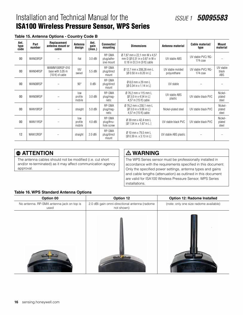
, ATTENTIONThe antenna cables should not be modified (i.e. cut short and/or re-terminated) as it may affect communication agency approval.
5.2 Protection of Antenna ConnectionsIf the antenna and connectors are not protected by the radome, the connector and threads should be protected from the ele-ments thorugh an application of protective tape.
• A recommended protective tape is COAX-SEAL® #104 Hand Moldable Plastic Weatherproofing Tape, available from electrical supply houses.
• Also acceptable is Scotch® Premium Vinyl Electrical Tape 88-Super tape, available from 3M.
Figure 9. Application of Protective TapeStep 1 - Remove radome. Step 2 - First apply 1/2 inch wide COAX-
SEAL® (flexible and moldable material)Step 3 - Secondly, apply 3M Scotch® Premium Vinyl Electrical Tape 88-Super
Ultimately, the antenna/cable choice may need to be tested in the actual application conditions to prove suitability for the environment.

Honeywell Sensing and Productivity Solutions 15
Installation and Technical Manual for the ISA100 Wireless Pressure Sensor, WPS Series
ISSUE 1 50095583
6 APPROVED ANTENNA TYPES/GAINS 6.1 Antenna DetailsThe following chart lists the antenna options along with the various characteristics that will be referenced throughout this section. This section is intended to assist an end user in determining which antenna(s) are worth investigating and subjecting to application requirements for proof of suitability.
Table 14. Antenna Options - Country Code A
Ant.type code
Part number
Replacement antenna mount or
cableAntenna design
Ant. gain
(max.)Connector/mounting Dimensions Antenna material Cable material/
typeMount
material
00 WAN03RSP – flat 3.0 dBi RP-SMA
plug/adhe-sive mount
Ø 7,87 mm x 22,1 mm W x 4,57 mm D [Ø 0.31 in x 0.87 in W x
0.18 in D] 3 m [9 ft] cable UV stable ABS UV stable PVC/ RG-
174 coax –
00 WAN04RSP WAMM100RSP-005
base with 1,52 m [5 ft] of cable
tilt/swivel 5.5 dBi
RP-SMA plug/direct
mount
Ø 12,7 mm x 208,28 mm L [Ø 0.50 in x 8.20 in L]
UV stable molded polyurethane
UV stable PVC/ RG-174 coax
UV stable black ABS
00 WAN04RSP WAMM100RSP-010 base with 3,05 m [10
ft] of cable
tilt/swivel 5.5 dBi
RP-SMA plug/direct
mount
Ø 12,7 mm x 208,28 mm L [Ø 0.50 in x 8.20 in L]
UV stable molded polyurethane
UV stable PVC/ RG-174 coax
UV stable black ABS
00 WAN05RSP WAMM100RSP-005
base with 1,52 m [5 ft] of cable
tilt/swivel 9.0 dBi
RP-SMA plug/direct
mount
Ø 12,7 mm x 384,05 mm L [Ø 0.50 in x 15.12 in L]
UV stable molded polyurethane
UV stable PVC/ RG-174 coax
UV stable black ABS
00 WAN05RSP WAMM100RSP-010 base with 3,05 m [10
ft] of cable
tilt/swivel 9.0 dBi
RP-SMA plug/direct
mount
Ø 12,7 mm x 384,05 mm L [Ø 0.50 in x 15.12 in L]
UV stable molded polyurethane
UV stable PVC/ RG-174 coax
UV stable black ABS
00 WAN06RNJ
WCA200RN-PRSP-002 coax cable
assembly 0,682 m [2 ft]
straight 8.0 dBi RP-N jack/ bracket
Ø 33,5 mm x 427,9 mm L [Ø 1.32 in x 16.85 in L] UV stable fiberglass
UV stable PVC/RG-316 coax, UV stable
Polyethylene/200 Series coax
300 se-ries SST
aluminum alloy
00 WAN06RNJ
WCA200RN-PRSP-010 coax cable
assembly 3,05 m [10 ft]
straight 8.0 dBi RP-N jack/ bracket
IØ 33,5 mm x 427,9 mm L [Ø 1.32 in x 16.85 in L] UV stable fiberglass
UV stable PVC/RG-316 coax, UV stable
Polyethylene/200 Series coax
300 se-ries SST
aluminum alloy
00 WAN08RSP – 90° 0 dBi RP-SMA
plug/direct mount
Ø 8,0 mm x 29 mm L [Ø 0.34 in x 1.14 in L] UV stable – –
00 WAN09RSP – low
profile mobile
3.0 dBi RP-SMA plug/mag-
netic
Ø 76,2 mm x 115 mm L [Ø 3.0 in x 4.54 in L] 4,57 m [15 ft] cable
UV stable ABS plastic UV stable black PVC
Nickel-plated steel
00 WAN10RSP – straight 5.0 dBi RP-SMA plug/mag-
netic
Ø 76,2 mm x 230,1 mm L [Ø 3.0 in x 9.06 in L] 4,57 m [15 ft] cable
Nickel-plated steel UV stable black PVC Nickel-plated steel
00 WAN11RSP – low
profile mobile
4.0 dBi RP-SMA plug/thru-hole screw
Ø 39 mm x 42,4 mm L [Ø 1.54 in x 1.67 in L ] UV stable black PVC UV stable black PVC
Nickel-plated steel
12 WAN12RSP – straight 2.0 dBi RP-SMA
plug/direct mount
Ø 10 mm x 79,5 mm L [Ø 0.39 in. x 3.13 in. L] UV stable ABS plastic – –
16 sensing.honeywell.com
Installation and Technical Manual for the ISA100 Wireless Pressure Sensor, WPS Series
ISSUE 1 50095583
, ATTENTIONThe antenna cables should not be modified (i.e. cut short and/or re-terminated) as it may affect communication agency approval.
Table 16. WPS Standard Antenna Options Option 00 Option 12 Option 12: Radome Installed
No antenna. RP-SMA antenna jack on top is used
2.0 dBi gain omni-directional antenna (radome not shown)
(note: only one size radome available)
Table 15. Antenna Options - Country Code B
Ant.type code
Part number
Replacement antenna mount or
cableAntenna design
Ant. gain
(max.)Connector/mounting Dimensions Antenna material Cable material/
typeMount
material
00 WAN03RSP – flat 3.0 dBi RP-SMA
plug/adhe-sive mount
Ø 7,87 mm x 22,1 mm W x 4,57 mm D [Ø 0.31 in x 0.87 in W x
0.18 in D] 3 m [9 ft] cable UV stable ABS UV stable PVC/ RG-
174 coax –
00 WAN04RSP WAMM100RSP-010
base with 3,05 m [10 ft] of cable
tilt/swivel 5.5 dBi
RP-SMA plug/direct
mount
Ø 12,7 mm x 208,28 mm L [Ø 0.50 in x 8.20 in L]
UV stable molded polyurethane
UV stable PVC/ RG-174 coax
UV stable black ABS
00 WAN08RSP – 90° 0 dBi RP-SMA
plug/direct mount
Ø 8,0 mm x 29 mm L [Ø 0.34 in x 1.14 in L] UV stable – –
00 WAN09RSP – low
profile mobile
3.0 dBi RP-SMA plug/mag-
netic
Ø 76,2 mm x 115 mm L [Ø 3.0 in x 4.54 in L] 4,57 m [15 ft] cable
UV stable ABS plastic UV stable black PVC
Nickel-plated steel
00 WAN10RSP – straight 5.0 dBi RP-SMA plug/mag-
netic
Ø 76,2 mm x 230,1 mm L [Ø 3.0 in x 9.06 in L] 4,57 m [15 ft] cable
Nickel-plated steel UV stable black PVC Nickel-plated steel
00 WAN11RSP – low
profile mobile
4.0 dBi RP-SMA plug/thru-hole screw
Ø 39 mm x 42,4 mm L [Ø 1.54 in x 1.67 in L ] UV stable black PVC UV stable black PVC
Nickel-plated steel
12 WAN12RSP – straight 2.0 dBi RP-SMA
plug/direct mount
Ø 10 mm x 79,5 mm L [Ø 0.39 in. x 3.13 in L] UV stable ABS plastic – –
m WARNINGThe WPS Series sensor must be professionally installed in accordance with the requirements specified in this document. Only the specified power settings, antenna types and gains and cable lengths (attenuation) as outlined in this document are valid for ISA100 Wireless Pressure Sensor, WPS Series installations.

Honeywell Sensing and Productivity Solutions 17
Installation and Technical Manual for the ISA100 Wireless Pressure Sensor, WPS Series
ISSUE 1 50095583
Figure 10. Radiation Pattern of an Omni-directional Antenna
Toroid Radiation Pattern - Pattern is 360 degrees in the vertical plane, but not the horizontal plane
2.0 dBi RF Antenna Pattern - Hori-zontal
2.0 dBi RF Antenna Pattern - Vertical
6.2 Omni-directional Antenna DesignThe omni-directional antennas offered were chosen for their abil-ity to be used in applications where transmit- and-receiver anten-nas may be moving with respect to each other or could also be stationary. They are dipole antennas that radiate power (power from the internal radio of the WPS) in a 360° outward pattern in a plane perpendicular to the length of the antenna element. “Omni” may suggest the antenna radiates power in all directions, but that is not the case. The actual antenna radiation pattern looks more like a toroid (doughnut-shape) as shown in Figure 10.
The antenna radiates virtually zero power in the Z axis and most of the power in the X and Y axis. Increasing the antenna’s gain will increase the power only in the X and Y axis. As a result, the radiation pattern becomes narrower. For instance, this is analo-gous to the reflector in an automobile’s headlight. The reflector does not add light or increase the luminous intensity of the light bulb, rather it simply directs all the light energy in the forward direction where the light is needed most.
Omni-directional antennas may obtain more gain in the horizontal plane by stacking multiple elements vertically, which decreases the radiation angle in the horizontal plane. Especially for these higher gain omni antennas, it is important to orient the antenna close to vertical. If the sensor cannot be mounted vertically, then a hinged antenna may be indicated.

18 sensing.honeywell.com
Installation and Technical Manual for the ISA100 Wireless Pressure Sensor, WPS Series
ISSUE 1 50095583
7 ANTENNA ADJUSTMENT AND MOUNTING
7.1 Requirements
7.1.1 Radio Installation Requirements
, ATTENTION• Professional Installation is required to ensure conformity
with Federal Communications Commission (FCC) in the USA, Industry Canada (IC) in Canada and the Radio and Telecommunications Terminal Equipment Directive, 1999/5/EC (R&TTE), in the European Union (EU).
• Professional installation is required for the selection and in-stallation of approved antennas and setup of the maximum allowable radiated power from the ISA100 Wireless Pres-sure Sensor, WPS Series as configured for the particular installation site.
• The antenna used for this sensor must be installed to provide a separation distance of at least 20 cm [7.87 in] from all persons and must not be co-located or operating in conjunction with any other antenna or sensor.
• For remote antenna, see antenna installation requirements to satisfy FCC RF exposure requirements.
, ATTENTIONFederal Communications Commission (FCC):
• The ISA100 Wireless Pressure Sensors, WPS Series com-ply with part 15 of the FCC rules. Operation is subject to the following two conditions: (1) this device may not cause harmful interference, and (2) this device must accept any interference received, including interference that may cause undesired operation.
Industry Canada (IC):
• L’installateur de cette radio doit s’assurer que l’antenne est située ou orientée de manière à ne pas émettre de radiofréquences excédant les limites permises par Santé Canada pour la population générale. Veuillez consulter le Code de sécurité 6 de Santé Canada au www.hc-sc.gc.ca/rpb.
7.2 Direct Mount Antenna
m WARNINGPOTENTIAL ELECTROSTATIC CHARGING HAZARD The direct mount antenna radome is made of plastic and has a surface resistivity greater than 1 Gohm per square. When the ISA100 Wireless Pressure Sensor, WPS Series is installed, care should be taken not to electrostatically charge the surface of the antenna shroud by rubbing the surface with a cloth, or cleaning the surface with a solvent.
7.2.1 Direct Mount, General GuidelinesA direct-mount straight antenna can be easily mounted by threading the mating RP-SMA plug of the antenna to the RP-SMA jack on the WPS. Tighten the connection until finger tight by holding the antenna above the straight knurl portion. For straight antennas, attach the antenna radome with the two screws provided. Ensure that the “O” ring is installed in the groove in the sensor housing.
7.2.2 Direct Mount, StraightFigure 11. Direct Mount Antenna Option 12 Radome Installed
Straight antenna available in 2 dBi configurations.
7.3 Remote Antennas
7.3.1 Outdoor Installation Warnings
m WARNINGLIVES MAY BE AT RISK! Carefully observe these instructions and any special instructions included with the equipment being installed.
m WARNINGCONTACTING POWER LINES COULD BE FATALLook over the site before beginning any installation and anticipate possible hazards, especially these:
• Make sure no power lines are near where possible contact can be made. Antennas, masts, towers, guy wires, or cables may lean or fall and contact these lines. People may be injured or killed if they are touching or holding any part of equipment when it contacts electric lines. Make sure there is NO possibility that equipment or personnel can come in contact directly or indirectly with power lines.
• Assume all overhead lines are power lines.• The horizontal distance from a tower, mast, or antenna to
the nearest power line should be at least twice the total length of the mast/antenna combination. This will ensure that the mast will not contact power if it falls during either installation or later.

Honeywell Sensing and Productivity Solutions 19
Installation and Technical Manual for the ISA100 Wireless Pressure Sensor, WPS Series
ISSUE 1 50095583
m WARNINGTO AVOID FALLING, USE SAFE PROCEDURES WHEN WORKING AT HEIGHTS ABOVE GROUND
• Select equipment locations that will allow safe, simple equipment installation
• Don’t work alone. A friend or co-worker can save a life if an accident happens.
• Use approved, non-conducting ladders and other safety equipment. Make sure all equipment is in good repair.
• If a tower or mast begins falling, don’t attempt to catch it. Stand back and let it fall.
• If anything such as a wire or mast does come in contact with a power line, DON’T TOUCH IT OR ATTEMPT TO MOVE IT. Instead, save a life by calling the power com-pany.
• Don’t attempt to erect antennas or towers on windy days.
m WARNINGMAKE SURE ALL TOWERS AND MASTS ARE SECURELY GROUNDED, AND ELECTRICAL CABLES CONNECTED TO ANTENNAS HAVE LIGHTNING ARRESTORS.This will help prevent fire damage or human injury in case of lightning, static build up, or short circuit within equipment connected to antenna.
• The base of the antenna mast or tower must be connected directly to the building protective ground or to one-or-more approved grounding rods, using 1 AWG ground wire and corrosion-resistant connectors.
• Refer to the National Electrical Code for grounding details.• Lightning arrestors for antenna feed coaxial cables are
available from electrical supply houses.
m WARNINGIf a person comes in contact with electrical power, and cannot moveDO NOT TOUCH THAT PERSON OR RISK ELECTROCUTION.
• Use a non-conductive dry board, stick, or rope to push, pull, or drag them so they no longer are in contact with electrical power.
• Once they are no longer contacting electrical power, administer CPR if certified, and make sure emergency medical aid has been requested.
7.3.2 Cable RequirementSome remote mount SMA connector antennas have an antenna cable permanently attached, with an RP-SMA plug, that is simply connected to the jack on the sensor. Other remote mount anten-nas do not include cable, and require the use of an extension cable. This extension cable will normally need to have one end with an RP-SMA plug (inside threads), which will connect to the sensor, and one end with an RP-SMA jack (outside threads). The jack of the extension cable will mate with the antenna or the lightning arrestor. If a lightning arrestor is connected this way, the antenna may be directly connected to the arrestor.
Note that at 2.4 GHz., typical antenna cables types have 0.5 dB of loss per meter (almost 5 dB for a ten meter cable, plus con-nector losses). Excessively long cable runs should be avoided if possible.
Refer to Section 6 for approved antenna options and Section 5 for approved cable options.
7.3.3 Lightning ArrestorThe lightning arrestor may be mounted directly on the sensor, or at the far end of the antenna cable, mounted to a sheet of metal in a through-hole. Generally, the choice should be made based on having the shortest, most direct path to a good, solid ground.
If the lightning arrestor is mounted directly on the sensor, use caution when attaching a grounding wire to the arrestor to avoid putting undue stress on the sensor’s antenna connector.
If the coax cable is to enter a building, then the lightning arrestor should be mounted as close as possible to where the lead-in wire enters the building. The lightning arrestor recommended by Hon-eywell features a bulkhead RP-SMA connector with a rubber “O”-ring seal which can be used for mounting through an enclosure wall. Both connector ports of the lightning arrestor provide equal protection no matter which way it is installed. Either port can face the antenna and either port can face the sensor.
7.3.4 Choosing a Mounting LocationThe location of the antenna is important. Objects such as metal columns, walls, etc. will reduce efficiency. Best performance is achieved when antennas for both Multinodes and WPS Series sensors are mounted at the same height and in a direct line of sight with no obstructions. If this is not possible and reception is poor, you try different mounting positions to optimize reception.
Antennas should be mounted clear of any obstructions to the sides of the radiating element. If the mounting location for an omni-directional antenna is on the side of a building or tower, then the antenna pattern will be degraded on the building or tower side.

20 sensing.honeywell.com
Installation and Technical Manual for the ISA100 Wireless Pressure Sensor, WPS Series
ISSUE 1 50095583
7.3.5 Site Selection Before attempting to install your antenna, consider the best place to install the antenna for safety and performance.
Follow these steps to determine a safe distance from wires, power lines, and trees.
Step Action
1 Measure the height of the antenna.
2 Add this length to the length of the tower or mast and then double this total for the minimum recommended safe distance.
Generally speaking, the higher the antenna is above the ground, the better it performs. Good practice is to install your antenna about 1,5 m to 3 m [5 ft to 10 ft] above the roof line and away from all power lines and obstructions. If possible, find a mounting place directly above the wireless device so the lead-in cable can be as direct as possible.
7.3.6 Antenna Mount TypesAntennas are provided with a variety of mounting options, includ-ing magnetic mount, tape mounting, or mast mounting. The standard 2.0 dBi antennas, normally mounted on the sensor, may also be mounted to an extender cable, if the remote cable end is mounted in a through hole with the nut and lockwasher. These antennas may also be mounted on a lightning arrestor, if the lightning arrestor is properly mounted in a through hole with a nut and lockwasher.
Omni-directional antennas are vertically polarized and produce a “doughnut” shaped pattern. It is very important to mount the an-tenna in a vertical (not leaning) position for optimal performance, especially with higher gain antennas.
7.3.7 Magnetic MountingIf a horizontal steel stuctural member or sheet metal area is avail-able, and there are no severe environmental conditions (wind, vibration, etc.), a magnetic mount antenna may be an easy solution. This also allows the option of easily making small adjust-ments to optimize R.F. path performance.
Using tie-wraps (cable ties), secure the coax cable to the nearby structural members, using a tie-wrap every 25 cm to 30 cm [9.84 in to 11.81 in].
Figure 12. Magnetic Mount Antenna

Honeywell Sensing and Productivity Solutions 21
Installation and Technical Manual for the ISA100 Wireless Pressure Sensor, WPS Series
ISSUE 1 50095583
Figure 13. Adhesive Mounting Steps
Step 1. Pre-clean the surface Step 2. Peel Protection from Adhe-sive Strip
Step 3. Mount the Antenna
7.3.8 Adhesive MountingThe benefit of the remote adhesive mount antenna is mounting flexibility to a number of surfaces and in various orientations. Note that the surface that the antenna is being mounted to will af-fect the radiation pattern so it is suggested that masking tape be used to temporarily attach the antenna. Evaluate R.F. link perfor-mance, as described in the Wireless Link Quality Measurement (see Section 7.6) paragraphs before permanently mounting.
Permanent mounting: Pre-clean the surface where the antenna is to be mounted with an alcohol wipe. Peel paper protection from adhesive strip and mount to the cleaned surface. See Figure 13.
7.3.9 Mast MountingMast mounting kits consist of a mounting bracket and one or two U-bolt clamps. These kits allow the bracket to be mounted to masts with outside diameters (O.D.) from 3,2 cm [1.25 in] to 5,1 cm [2 in]. Honeywell recommends that a 3,8 cm [1.5 in] or larger tubing mast be used. The antenna is then mounted in a hole on the bracket upper surface. Most standard brackets will have a hole too large for an SMA mount antenna, so a new hole will be needed. For hole dimensions, refer to Figure 8, WPS Antenna Extender Cable Mounting Hole.

22 sensing.honeywell.com
Installation and Technical Manual for the ISA100 Wireless Pressure Sensor, WPS Series
ISSUE 1 50095583
Follow these steps to mount the antenna on a mast.
Step Action
1 Assemble the new antenna on the ground at the installation site. For SMA mount antennas, mount the RP-SMA jack of the antenna cable to a hole in the bracket, using the nut and lockwasher supplied. For lightning arrestor mounting, mount the lightning arrestor in the mounting bracket hole, and attach the extension cable to the arrestor.
2 Screw the SMA antenna onto the cable or lightning arrestor. Tighten all cables by hand only; do not use tools or you could overtighten. Make sure that the connections are sealed (if outdoors) the prevent moisture and other weathering elements from effecting performance. Honeywell recommends using a weathering tape (such as COAX-SEAL® #104 from electrical supply houses, or Super 88 tape from 3M) for outdoor connections. Silicon sealant or ordinary electrical tape is not recommended for sealing out door connections.
3 Attach the antenna bracket to the mast, using the U-Bolts as required.
4 Using tie-wraps (cable ties), secure the coax cable to the mast, using a tie-wrap every 25 cm to 30 cm [9.84 in to 11.81 in].
5 Follow standard strain relief practice when installing the antenna cable. Avoid excessive strain, bending, kinks, or crushing (stepping on or placing any weight on cable) before, during, or after the coax cable is secured in its final position.
6 Make sure the mast does not fall the “wrong way” should you lose control as you raise or take down the mast. Use a durable non-conductive rope. Have an assistant tend to the rope; ready to pull the mast clear of any hazards (such as power lines) should it begin to fall.
7 If the installation will use guy wires: • Install guy anchor bolts. • Estimate the length of guy wire and cut it before raising the mast. • Attach guy wires to a mast using guy rings.
8 Carefully connect the antenna and mast assembly to its mounting bracket and tighten the clamp bolts. In the case of a guyed installation, you must have at least one assistant to hold the mast upright while the guy wires are at-tached and tightened to the anchor bolts.
9 Attach a "DANGER" label at eye level on the mast.
10 Install ground rods to remove any static electricity buildup and connect a ground wire to the mast and ground rod. Use ground rods designed for that purpose; do not use a spare piece of pipe.
11 When attaching the coax cable to the WPS Series, it is recommended that a drip loop with a radius of at least 30 cm [11.81 in] be formed close to the WPS Series. This will minimize ice and water buildup on the sensor itself. Tighten cables by hand only; do not use tools or you could overtighten and damage the RF cable on the sensor.
To lightningarrestor and antenna
Drip loop
30 cm[12 in]

Honeywell Sensing and Productivity Solutions 23
Installation and Technical Manual for the ISA100 Wireless Pressure Sensor, WPS Series
ISSUE 1 50095583
7.3.10 Grounding the AntennaFollow these guidelines to ground the antenna in accordance with national electrical code instructions.
Step Action
1 Use No. 10 AWG copper or No. 8 or larger copper-clad steel or bronze wire as ground wires for both mast and lead-in. Securely clamp the wire to the bottom of the mast.
2 Secure the lead-in wire to a lightning arrestor and mast ground wire to the building with stand-off insulators spaced from 1,2 m [4 ft] to 1,8 m [8 ft] apart.
3 The lightning arrestor must be bonded to earth ground in order to function properly. Due to the small diameter coaxial cables used with the RP-SMA connectors, the lightning arrestor must be grounded independant of the antennas, using number 10 solid wire. This wire must be connected directly to a solid ground. It may be the same ground as is used for the antenna tower.
4 Drill a hole in the building’s wall as close as possible to the equipment to which you will connect the lead-in cable. Use a rubber grommet or feedthru tube to protect the cable from abrasion.
m CAUTIONThere may be wires in the wall. Before drilling check that the area is clear of any obstructions or other hazards.
5 Pull the cable through the hole and form a drip loop on the outside close to where the cable enters the building. The drip loop should have a radius of at least 30 cm [11.81 in].
To lightningarrestor and antenna
Drip loop
30 cm[12 in]
6 Thoroughly waterproof the lead-in area.
7 Connect the lead-in cable to the WPS Series sensor. Tighten cables by hand only; do not use tools or you could overtighten and damage the RF cable on the sensor.

24 sensing.honeywell.com
Installation and Technical Manual for the ISA100 Wireless Pressure Sensor, WPS Series
ISSUE 1 50095583
7.3.11 Connection Diagrams for Remote Antenna Configuration
Figure 14. WPS Connected to Remote Antenna Remotely
WPSWireless Pressure
Sensor
RemoteAntenna
RF Cable A or B
Figure 15. WPS Connected to Remote Antenna Via Lighting Arrestor
WPSWireless Pressure
Sensor
RemoteAntenna
RF Cable A or B
LightingArrestorRF Cable B
NOTES:
1. Recommended lightning arrestor from electrical supply houses, part number: AL6-RSPRSJBW-9
2. Approved remote antennas are listed in Section 6.
7.4 Antenna Mounting Considerations
7.4.1 Antenna Mounting Location with Respect to RF Signal
m WARNINGRF EXPOSURETo satisfy FCC RF exposure requirements for mobile transmit-ting devices, a separation distance of 20 cm [7.87 in] or more should be maintained between the antenna of this device and persons during device operation. To ensure compliance, operation at closer than this distance is not recommended. The antenna used for this transmission must not be co-located in conjunction with any other antenna or sensor.
Failure to comply with these instructions could result in death or serious injury.
m WARNINGLIVES MAY BE AT RISK! Carefully observe these instructions and any special instructions included with the equipment being installed.
m WARNINGCONTACTING POWER LINES COULD BE FATALLook over the site before beginning any installation and anticipate possible hazards, especially these:
• Make sure no power lines are near where possible contact can be made. Antennas, masts, towers, guy wires, or cables may lean or fall and contact these lines. People may be injured or killed if they are touching or holding any part of equipment when it contacts electric lines. Make sure there is NO possibility that equipment or personnel can come in contact directly or indirectly with power lines.
• Assume all overhead lines are power lines.• The horizontal distance from a tower, mast, or antenna to
the nearest power line should be at least twice the total length of the mast/antenna combination. This will ensure that the mast will not contact power if it falls during either installation or later.
m WARNINGTO AVOID FALLING, USE SAFE PROCEDURES WHEN WORKING AT HEIGHTS ABOVE GROUND
• Select equipment locations that will allow safe, simple equipment installation
• Don’t work alone. A friend or co-worker can save a life if an accident happens.
• Use approved, non-conducting ladders and other safety equipment. Make sure all equipment is in good repair.
• If a tower or mast begins falling, don’t attempt to catch it. Stand back and let it fall.
• If anything such as a wire or mast does come in contact with a power line, DON’T TOUCH IT OR ATTEMPT TO MOVE IT. Instead, save a life by calling the power com-pany.
• Don’t attempt to erect antennas or towers on windy days.
m WARNINGMAKE SURE ALL TOWERS AND MASTS ARE SECURELY GROUNDED, AND ELECTRICAL CABLES CONNECTED TO ANTENNAS HAVE LIGHTNING ARRESTORS.This will help prevent fire damage or human injury in case of lightning, static build up, or short circuit within equipment connected to antenna.
• The base of the antenna mast or tower must be connected directly to the building protective ground or to one-or-more approved grounding rods, using 1 AWG ground wire and corrosion-resistant connectors.
• Refer to the National Electrical Code for grounding details.• Lightning arrestors for antenna feed coaxial cables are
available from electrical supply houses.

Honeywell Sensing and Productivity Solutions 25
Installation and Technical Manual for the ISA100 Wireless Pressure Sensor, WPS Series
ISSUE 1 50095583
m WARNINGIf a person comes in contact with electrical power, and cannot moveDO NOT TOUCH THAT PERSON OR RISK ELECTROCUTION.
• Use a non-conductive dry board, stick, or rope to push, pull, or drag them so they no longer are in contact with electrical power.
• Once they are no longer contacting electrical power, administer CPR if certified, and make sure emergency medical aid has been requested.
7.4.2 Antenna Mounting Location with Respect to Antenna Location
There are several environmental factors to consider with respect to antenna location during installation. These factors can affect the radio frequency (RF) signal strength being both transmitted and received by the WPS and corresponding Field Device Ac-cess Point (FDAP). It is desirable for the antenna to be mounted to limit exposure of adjacent materials/objects between the Hon-eywell WPS and FDAP, as they will have an effect on RF signal strength. If the mounting location for an omni-directional antenna is on the side of a building or tower, the antenna pattern will be degraded on the building or tower side.
Obstacles that affect antenna patterns and RF signal strength:
• Indoor: Concrete, wood, drywall, and metal walls, etc.
• Outdoor: Vehicles, buildings, trees, structures, topol-ogy, weather conditions, chain link fence, major power cables, etc.
Rain and moisture: Wireless sensors compliant with IEEE 802.15.4 operate in a 2.4 GHz band. As the peak absorption frequency of water molecules is approximately 22 GHz, the total signal attenuation due to rain, fog or moisture is negligable (less than 0.1 dB/mile for a heavy downpour).
7.4.3 Line of Sight ConsiderationsBest performance is achieved when antennas for both the WPS Wireless Pressure Sensor and FDAP are mounted at the same height and in a direct line of sight (LOS) with no obstructions, and with both antennas vertical. Generally, the higher the antenna is above ground, the better it performs.
Figure 16. WPS to FDAP Antennas with RF Signal Line of Sight (LOS) Free From Obstacles
Figure 17. WPS to FDAP Antennas with RF Signal Line of Sight (LOS) Affected by Obstacles

26 sensing.honeywell.com
Installation and Technical Manual for the ISA100 Wireless Pressure Sensor, WPS Series
ISSUE 1 50095583
7.5 R.F. Interference Considerations
7.5.1. GeneralThe 802.15.4 specification provides a high resistance to inter-ference. Within the 2.4 GHz band, there are 16 channels, each using approximately 2 MHz of bandwidth. The channel used may be rapidly changed depending on the presence of other signals sensed in that channel. Thus narrow band interfering signals may have no effect, while broadband noise sources may cause loss. The effect of light to moderate interference is not to make the sys-tem fail, but to increase the rate of “lost packets” of data. These “lost packets” are simply retransmitted as needed, so the user may not notice any problem. More serious interference can cause loss of more data updates, and error messages reported by the WDM, as well as shorter battery life.
7.5.2 WiFi NetworksMost WiFi (WLAN) networks operate in the same 2.4 GHz range and use wider bands within that range. Also, the faster protocols (802.11N or AC), may utilize multiple channels. Factors affecting R.F. interference would be channel separation, distance separa-tion, and duty cycle.
• Channel separation: Studies have shown that a channel separation of 7 MHz will make interference less likely. WiFi routers can be set to use different channels as needed, and auto channel modes can be disabled. If possible, switch-ing to a 5 GHz-only protocol (using 802.11N or AC), would eliminate any possibility of 2.4 GHz interference. The WDM may be set to not use certain 802.15.4 channels.
• Distance separation: A physical separation of 10 meters or more will reduce possibility of interference.
• Duty Cycle: Generally the duty cycle of WiFi routers is very low for simple uses as e-mailing, messaging, most web browsing, and voice protocols. However, a video camera or multiple users streaming video would cause a significant increase in bandwidth usage and increase the possibility of interference, making channel or distance separation more desirable.
Regarding the WiFi client (laptop, smartphone, tablet), they are much less of a problem as they generally operate with a much reduced duty cycle (most data is received by the device), and may operate with much lower transmit power
7.5.3 Smart Phone “Apps”Smart phone “apps” are available to display consumer WIFI signal strengths or download/upload speeds. These apps will not display the 802.15.4 signals as the packet format is different. However, if a suspected interference source causes a large re-duction in consumer WiFi download speed, it is likely it could also cause interference to the 802.15.4 data used by the WPS.
7.5.4 Bluetooth® DevicesBluetooth® interference is less of an issue, due to the very narrow bandwidth of Bluetooth® signals, the low transmit power, and the rapid “frequency hopping” of the signals. If the 802.15.4 device misses a packet of data due to a Bluetooth® burst of data, the re-transmission of the 802.15.4 data will likely succeed, as the Bluetooth® will have hopped to a different channel by then.
7.5.5 Wireless Video Camera and Video LinksWireless video links operating in the 2.4 GHz band can cause se-rious interference as they are operating continuously, use a wide (6 MHz) bandwidth), and may be more powerful. Interference from wireless video could cause the “NO RF” indication in severe cases. As mentioned, frequency and/or distance separation may be required.
• Frequency Separation: Many video links have four or more channels selectable. Changing channels may help. Addition-ally, wireless video links are available in the 900 MHz band, and the 1.2 GHz band. Switching to one of those would elimi-nate interference issues with 802.15.4 (and 802.11x).
• Distance Separation: Separating the video link sensor from the wireless sensor would be very desirable. Alternatively, utilizing directional antennas on the wireless sensor, and /or on the wireless video link would help greatly.
7.5.6 Microwave OvensMicrowave ovens operate in the 2.4 GHz range, they are power-ful, and a high-duty cycle. However, they may not be a problem to a modern 802.15.4 network. The magnetron in a microwave oven is driven by half-wave rectified AC, so the R.F. output is ac-tually off for one half of the 60 Hz or 50 Hz power line cycle (8.33 msec or 10.0 msec). During that part of the cycle, the packets of 802.15.4 data may succeed. However, close to half of the packets may require retransmission, so data throughput could be greatly reduced.
7.5.7 Cordless Phones/Baby Monitors/IntercomsA 2.4 GHz cordless phone in very close proximity to a wireless sensor could cause lost packets, while the phone is in use, but is not a very likely cause. If monitoring the link quality as in “link measurements” above, shows interference, a simple remedy is to switch to a DECT 6.0 cordless phone operating on 1.9 GHz.

Honeywell Sensing and Productivity Solutions 27
Installation and Technical Manual for the ISA100 Wireless Pressure Sensor, WPS Series
ISSUE 1 50095583
7.6 Wireless Link Quality Measurements
7.6.1 Link MeasurementsThere are two methods of observing the R.F. link performance
• The LCD on the WPS sensor will display the R.F. link quality as one of four values; BEST, GOOD, BAD, and NO RF, based upon the link analysis.
• The Map View on the OneWireless™ User Interface will show a link number in a small block on the line between sensor and AP. Hovering over this block will show a larger block of link status info:
Figure 18. R.F. Link Quality Data Block Shown on One-Wireless™ User Interface Map View
RSQI is the Received Signal Quality Indicator value, lowest value/highest value. Higher values are better.
RSSI is the Received Signal Strength Indicator value, lowest value/highest value. The less negative the values, the stronger the signal (-60 dBm is stronger than -70 dBm).
TxFailRatio is related to the percentage of dropped data pack-ets. Low values are better, high values may be an indication of poor link quality or interference
7.6.2 Connection Quality LabelsLink quality details can be categorized as poor, fair, good, etc. The default numerical criteria for these labels as per the One-Wireless™ Network Planning and Installation Guide (OWDOC-X253) are
Table 17. WPS Connection Quality Labels Quality Detail Numerical Value Label
RSQI range 196 to 255 Excellent
128 to 195 Good
64 to 127 Fair
0 to 63 Poor
RSSI range
-75 to -25 Good
-85 to -75 Fair
-100 to -85 Poor
TxFailRatio
0 to 25 Good
25 to 50 Fair
50 to 100 Poor (For WDM operations and setting alarms and thresholds, refer to OneWireless™ Wireless Device Manager User’s Guide, OW-DOC-X254.)

28 sensing.honeywell.com
Installation and Technical Manual for the ISA100 Wireless Pressure Sensor, WPS Series
ISSUE 1 50095583
8 EQUIVALENT ISOTROPICALLY RADIATED POWER (EIRP)In radio communication systems, Equivalent Isotropically Radi-ated Power (EIRP) or, alternatively, Effective Isotropic Radiated Power, is the amount of power that would have to be emitted by an isotropic antenna (that evenly distributes power in all direc-tions and is a theoretical construct) to produce the peak power density observed in the direction of maximum antenna gain. EIRP can take into account the losses in transmission line and connectors and includes the gain of the antenna. The EIRP is
often stated in terms of decibels over a reference power level that would be the power emitted by an isotropic radiator with an equivalent signal strength. The EIRP allows making comparisons between different emitters regardless of type, size or form. From the EIRP, and with knowledge of a real antenna’s gain, it is pos-sible to calculate real power and field strength values.
EIRP(dBm) = Radio TX Power (dBm) – Cable Loss, including Lightning Arrestor loss (dB) + Antenna Gain(dBi)
Antenna gain is expressed relative to a (theoretical) isotropic reference antenna (dBi).
8.1 EIRP Limits and TX Power Setting
Table 18. Maximum EIRP Limits and Radio Module TX Power Setting Antenna Part Num-ber
Antenna Type
Radio Usage/
Application
Frequency (GHz)
Max. An-tenna Gain
(dBi)
Min. Cable Length (ft)
Min. Cable Loss (dB)
Agency/ Country
Max. TX Power Set-ting (dBm)
Max. EIRP (dBm)
WAN03RSP
Omni-direc-tional
Remote 2.4 GHz3.0 9.8 7.35 FCC, IC 15 10.7
3.0 9.8 7.35 ETSI 6 1.7
WAN04RSP Integral 2.4 GHz5.5 0 0.00 FCC, IC 11 16.5
5.5 0 0.00 ETSI 2 7.5
WAN05RSP Integral 2.4 GHz9.0 0 0.00 FCC, IC 11 20.0
9.0 0 0.00 ETSI -0.5 8.5
WAN06RNJ Remote 2.4 GHz
8.0 3 0.76 FCC, IC 15 22.2
8.0 11 2.11 FCC, IC 15 20.9
8.0 3 0.76 ETSI -0.5 6.7
8.0 11 2.11 ETSI -0.5 5.4
WAN08RSP Integral 2.4 GHz0.0 0 0.00 FCC, IC 15 15.0
0.0 0 0.00 ETSI 6 6.0
WAN09RSP Remote 2.4 GHz3.0 15 2.81 FCC, IC 15 15.2
3.0 15 2.81 ETSI 6 6.2
WAN10RSP Remote 2.4 GHz5.0 15 2.81 FCC, IC 11 13.2
5.0 15 2.81 ETSI 2 4.2
WAN11RSP Remote 2.4 GHz4.0 9.8 1.66 FCC, IC 15 17.3
4.0 9.8 1.66 ETSI 4 6.3
WAN12RSP Integral 2.4 GHz2.0 0 0.00 FCC, IC 15 17.0
2.0 0 0.00 ETSI 6 8.0
1 The Maximum TX Power Setting values given in Table 18 represent the power produced by the radio circuit within the RF Module. These maximum TX power setting values do not include antenna gain nor do they include the losses caused by cables and connectors. When these external gains and losses are included, then using these maximum TX power setting values ensures that the WPS Series EIRP will not exceed the maximum EIRP limits that are given in Table 18.
2 The values in the above tables have been determined through agency certification testing.3 The following shall apply for antenna type, frequency range, application/usage and agency/country compliance: • Antenna gains above the maximum values shown shall not be used. • Cable length/loss below the minimum values shown shall not be used. • Maximum overall radio output power shown shall not be exceeded. • Maximum EIRP values shown above shall not be exceeded.4 France restricts outdoor use to 10 mW (10 dBm) EIRP in the frequency range of 2,454 MHz to 2,483.5 MHz. Installations in France must limit EIRP to
10 dBm for operating modes utilizing frequencies in the range of 2,454 to 2,483.5 MHz.5 Industry Canada Compliance Statement: This device has been designed to operate with the antenna types listed in this document, and having a
maximum gain of 14 dBi. Antenna types not included in this list or having a gain greater than 14 dBi are strictly prohibited for use with this device. The required antenna impedance is 50 ohms.

Honeywell Sensing and Productivity Solutions 29
Installation and Technical Manual for the ISA100 Wireless Pressure Sensor, WPS Series
ISSUE 1 50095583
9 OPERATING ONEWIRELESS™ USER INTERFACE
9.1 Overview of the OneWireless™ User InterfaceOneWireless™ user interface comprises of the following main ele-ments (refer to Figure 19):
1. Ribbon bar — Consists of the monitoring tab, alarms/events tab and the reports tab. It consists of groupings of user interface controls for controlling display elements and accessing various functions for monitoring and maintaining the ISA100 Wireless™ Network. These user interface controls are contextual and are enabled based on user role and devices/channels selected in the selec-tion panel or the map view.
2. Map view – Provides a visual representation of the ISA100 Wireless™ Network.
3. Selection panel – Displays a list of all the devices that are configured in the ISA100 Wireless™ Network.
4. Property panel – Contains configuration properties of all the devices configured in the ISA100 Wireless™ Network.
5. Status bar – Provides an overview of the network status by displaying the number of online devices, active alarms, WDM redundancy status, and the progress of any maintenance operation.
(For WDM operations and procedures, refer to OneWireless™ Wireless Device Manager User’s Guide, OWDOC-X254).
Figure 19. OneWireless™ User Interface Screen
9.2 Provisioning the OneWireless™ User Interface
9.2.1 Connecting to ISA100 Network1. Enable the FDAP (or MNBR) for provisioning.
a. Select the FDAP (or MNBR) in the OneWireless™ User Interface Home Screen on the selection panel (see Figure 20).
b. Expand ‘Device Parameters’ in the property panel and scroll down to ‘Over The Air Provisioning’ (see Figure 21).
c. Click on ‘Enable for 60 Minutes’ button to enable FDAP (or MNBR) for accepting devices over the network (see Figure 21).
Figure 20. Tag Name Figure 21. Enable for 60 Minutes Button
2. Provision the WPS device into the Network.
a. Remove the insulator tab from the battery holder to power-on the WPS device.
Note: If the device was already provisioned once before, it would be required to perform ‘Restore to Factory Defaults’ by pressing the reset button for >12 sec before it is ready to be provisioned again (see Figure 34).
b. WPS device will appear in the OneWireless™ User Interface home screen, on the selection panel as a new device and will be in gray color (see Figure 22).
Note: A fresh, out-of-box WPS device will appear with a Tag name as Txxxxxxxxxxxxxxx, where the 15-digit ‘x’ are usually the MAC ID of the device.

30 sensing.honeywell.com
Installation and Technical Manual for the ISA100 Wireless Pressure Sensor, WPS Series
ISSUE 1 50095583
Figure 22. Tag Name Pop-up Box
c. Select the device and click on the ‘Accept’ button in the top ribbon bar (see Figure 23).
Figure 23. Accept Button on Ribbon Bar
d. In the pop-up window that appears, select the device and click on ‘Accept’ (see Figure 24).
Figure 24. Accept Button Pop-Up Window
e. The device icon will turn blue and then to green color.
Note: This process may take time varying from one minute to five minutes
f. The device icon in green indicates the device is now provisioned into the ISA100 Wireless™ Net-work.
g. OPTIONAL: One can rename the device to enable better clarity of either the location it is installed or the purpose. This can be achieved by selecting the WPS device in the OneWireless™ User Interface home screen on the selection panel (see Figure 25), expand ‘Field Device Summary’ on the property panel (see Figure 26) and against ‘Tag Name:’ field enter the corresponding Tag Name.
Figure 25. Select the WPS Device in the Selection Panel
Figure 26. Tag Name Field Entry

Honeywell Sensing and Productivity Solutions 31
Installation and Technical Manual for the ISA100 Wireless Pressure Sensor, WPS Series
ISSUE 1 50095583
9.3 Channel Activation on the WPS Sensor1. Expand on the WPS Sensor in the Selection Panel and
select the channel. Note: One or more channel(s) may appear under a given device depending on the number of AITB blocks supported by the respective device. Also, the channel will appear only after the device is provisioned into the ISA100 Wireless™ Network.
Figure 27. Select Channel on Selection Panel
2. Click on the ‘Activate’ button in the ribbon bar
Figure 28. Activate Button on Ribbon Bar
3. In the pop-up window that appears, select the device and click on ‘Activate’.
Figure 29. Pop-Up Window
4. The channel icon will turn from BLUE to GREEN color indicating the activation process is complete. Details of what parameters the channel contains will be available on the property panel.
Figure 30. Channel Icon
Figure 31. Channel Information Property Panel Parameters

32 sensing.honeywell.com
Installation and Technical Manual for the ISA100 Wireless Pressure Sensor, WPS Series
ISSUE 1 50095583
9.4 Setting TX Power
9.4.1 TX Power Setting Policy
m WARNINGThe ISA100 Wireless Pressure Sensor, WPS Series must be professionally installed in accordance with the requirements specified in this document. Only the specified power settings, antenna types and gains and cable lengths (attenuation) as outlined in this document are valid for ISA100 Wireless Pres-sure Sensor, WPS Series installations.
Failure to comply with these instructions could result in death or serious injury.
The WPS Series as shipped from the factory will have its TX power value set according to its model number and this value is consistent with those values given in Table 18.
The TX power setting may be changed over the air using the OneWireless™ User Interface. Due to radio approval body regulations, changing the TX power setting is only available to the professional installer.
The TX power adjustment feature is provided for Professional Installers to adjust the ISA100 Wireless Pressure Sensor, WPS Series TX power to match a change in the selection of antenna and cables made at the installation site and still ensure that the EIRP does not exceed the regulatory limits.
9.4.2 Power Setting Procedure(For WDM operations and procedures, refer to OneWireless™ Wireless Device Manager User’s Guide, OWDOC-X254).
1. From Table 18, determine the new power setting to be set, based on the new antenna config.
2. Log into the OneWireless™ User Interface with a user account and password having suitable access privi-leges.
3. Ensure that the WPS device to be set has been success-fully provisioned.
4. On the selection panel, click on the Sensing Device to be set.
5. On the property panel, click on “Data Layer Manage-ment”.
6. Enter the new power level number in dBm and press Enter.
7. On the OneWireless™ User Interface Map View, verify that the link quality data block shows an acceptable link quality (see Figure 18).
8. Log off the OneWireless™ User Interface account.
Figure 32. R.F. Power Setting Procedure Using OneWire-less™ User Interface
9.5 Reading Battery Voltage
9.5.1 Reading Sensor Battery VoltageThe OneWireless™ User Interface allows the reading of the cur-rent battery voltage of the sensor by the following:
1. Log into the OneWireless™ User Interface using any ac-count.
2. On the selection panel, click the sensor name (not the channel name).
3. On the property panel, click on “Device Vendor Param-eters”. Read the battery voltage.
4. Log off the OneWireless™ User Interface account.
Figure 33. Battery Voltage
Note that a number of alerts may be enabled and configured in this dialog box. (For WDM operations and procedures, refer to OneWireless ™ Wireless Device Manager’s User’s Guide, OWDOC-X254.)

Honeywell Sensing and Productivity Solutions 33
Installation and Technical Manual for the ISA100 Wireless Pressure Sensor, WPS Series
ISSUE 1 50095583
9.6 Restore to Factory DefaultsThe WPS device can be restored to factory default settings by pressing and holding the reset button for >12 seconds. The reset button must be held pressed until the reset (green) LED turns off, indicating successful restoration to factory defaults. Figure 34 shows the location of the reset button and LED.
Figure 34. Location of Reset Button
9.7 Calibrating the SensorThe ISA100 Wireless Pressure Sensor, WPS Series is factory calibrated at time of manufacture. The calibration parameters are permanently stored in flash of microcontroller in the interface board. There is no user calibration routine available.
10 FUNCTION BLOCKS
10.1 IntroductionThis section explains the construction and contents of the WPS Series sensor function blocks.
10.1.1 ConfigurationThe WPS Series sensor contains an electronics interface compat-ible for connecting to the ISA100 Wireless™ network. An operator uses the OneWireless™ User Interface to configure the sensor, to change operating parameters, and to create linkages between blocks that make up the sensor’s configuration. These changes are written to the sensor when it is authenticated by a security key.
10.2 Data Block Description
10.2.1 Data Block TypesData blocks are the key elements that make up the sensor’s configuration. The blocks contain data (block objects and pa-rameters) which define the application, such as the inputs and outputs, signal processing and connections to other applications. The WPS Series sensor contains the following block types.
Table 19. Block TypesBlock type Function
Device
Contains parameters related to the overall field device rather than a specific input or output chan-nel within it. A field device has exactly one device block.
AITB
Contains parameters related to a specific process input or output channel in a measurement or ac-tuation device. An AITB defines a measurement sensor channel for an analog process variable represented by a floating-point value. There is one AITB per sensor.
RadioContains parameters related to radio communica-tion between the sensor and the multinode(s).
Each of these blocks contains parameters that are standard ISA100-sensor defined parameters. The AITB and device blocks contain standard parameters common to all ISA100-compliant sensors as well as model-specific parameters. The radio block contains parameters for communication with the wireless net-work.
The OneWireless™ User Interface manages the data flow to and from the sensors. It is aware of the relevant data blocks for the various sensors in the system through the use of the DD files (De-vice Description Files). As part of the provisioning process, a DD file for the WPS Series sensors is loaded into the OneWireless™

34 sensing.honeywell.com
Installation and Technical Manual for the ISA100 Wireless Pressure Sensor, WPS Series
ISSUE 1 50095583
system. This is must be done prior to connecting the first WPS Series sensor to the system. Refer to the OneWireless™ Wireless Device Manager User’s Guide OWDOC-X254 for procedures.
10.3 Hardware Description
10.3.1 Detailed Block DiagramThe ISA100 Wireless Pressure Sensor, WPS Series contains the following functional components:
1. Sensor module
2. Interface board
3. Radio board
4. LCD display
5. Battery
Figure 2 shows the detailed block diagram of the WPS Series sensor.
10.3.2 Sensor ModuleTwo versions are available, GP (gage pressure), or AP (absolute pressure). For the gage pressure models, a vent feature is provid-ed on the front cover. Electrical signals from the sensor connect to signal conditioning circuit on the interface board.
10.3.3 Interface BoardThe microprocessor internally constitutes of a flash, non-volatile memory containing:
• Characterization data, loaded at time of manufacture, that identifies the specific measurement hardware installed, pressure range, burst pressure, GP or AP type, etc. Also stored are the default user settings. After a hard reset (cold restart), any user settings are replaced with the default user settings. None of the characteriza-tion data is user changeable.
• Calibration data, from the factory calibration procedure. This data is not unerasable nor changeable.
• Program code, loaded or updated over the air, through the OneWireless™ User Interface
• User settings, selected through the OneWireless™ User Interface, such as periodic update interval, LCD display timing, measurement units, etc.
A small reset button and green LED are mounted on the interface board, used to cause a restore to factory default state.
10.3.4 Radio BoardThe radio board contains a microprocessor with EEPROM to store its program code and operating parameters. These parameters include channel selection, link options, and other mode options, as set though the OneWireless™ User Interface. A small R.F. con-nector on the radio board is connected to a short cable assembly containing the sensor external antenna connector.
m CAUTIONApplying power to the device/product with no antenna connected to the radio board could cause permanent damage to the device or the radio board.
10.3.5 LCD DisplayThe optional LCD display is connected through a cable assembly to the interface board. It is activated as required, by the interface board, in accordance with the LCD timing user options.
10.3.6 BatteryThe battery consists of two each, D-sized Lithium Thionyl Chlo-ride cells. Each cell provides 3.6 Vdc and the two cells are wired in series to provide 7.2 Vdc to operate all circuits in the sensor. There is no on/off switching, so when the batteries are installed, the sensor is active. See Section 11.3 for battery considerations and see Table 25 for battery replacement procedures.
10.3.7 Battery LifeThe battery life depends on four factors:
• Periodic update interval - Setting a higher periodic up-date interval increases battery consumption
• LCD display timing - Setting the LCD to display continu-ously or for longer periods will increase battery con-sumption.
• R.F. link data re-transmissions - When the ISA100 Wire-less Pressure Sensor, WPS Series needs to send a packet of data to the nearest AP (publish), it transmits the packet and waits for an acknowledgement. Normally, it receives the acknowledgement immediately, stops, and waits for the next scheduled transmission time. A long R.F. path, interfering materials (metal structures, etc.), or R.F. interference from other nearby transmitters, may cause the transmitted packet to be “dropped”. If this occurs, the sensor will re-try to send the packet. It will re-try two more times, waiting for an acknowledge-ment. These extra re-transmissions will greatly increase the battery usage and reduce battery life.

Honeywell Sensing and Productivity Solutions 35
Installation and Technical Manual for the ISA100 Wireless Pressure Sensor, WPS Series
ISSUE 1 50095583
• Operating in “Router” mode - When the ISA100 Wire-less Pressure Sensor, WPS Series is configured to act as a ‘routing device’ in an ISA100 Wireless™ Network, as defined by the ISA100 architecture, this device stays awake almost all the time which can increase battery consumption.
Typical battery life is estimated to be as much as 6.5 years for 60 second periodic update intervals, 5 years for 5 second periodic update intervals, and as low as 2.5 years for 1 second periodic update intervals.
11 OPERATION
11.1 Overview
11.1.1 Display ModesThe sensor has the following display modes.
• PV display: Displays the process value and units
• Connection (Link) status: Displays a label calculated from the link signal amplitude
• Battery status: Displays a warning label in the event of a low battery condition
11.2 Sensor PV DisplayOn the LCD display, the following information is displayed in se-quence. First, the PV will be displayed for three seconds, then the link status will be displayed for two seconds. This sequence will repeat at a rate determined by the periodic update interval and the LCD display rate.
Table 20. PV Display
Item Displayed Example Details
PV value 50.0 Latest PV value
PV engineering units
psig See Table 21
Link status GOOD Received signal strength - See Table 22 Sensor Link Status Display
Table 21. PV Engineering Units
Item Displayed Details
Pa Pascals1
kPa KiloPascals
bar bar2
mbar Millibar
psia Pounds per square inch absolute
psig Pounds per square inch gage
1 Values greater than 10,000 Pa will be automatically converted to kPa and displayed on the LCD.2 Values lesser than 1 bar will be automatically converted to mbar (mil-libar) and displayed on the LCD.
Table 22. Sensor Link Status Display
Display Meaning Suggested Action
BEST Best strength – approx. -75 dBm to -25 dBm
• No action required
GOOD Good strength – approx. -75 dBm to -85 dBm
• No action required
BAD Very weak signal – approx. -100 dBm to -85 dBm
• Troubleshoot antenna, antenna cables
• Evaluate signal path and distance to nearest FDAP
• Substitute other provisioned sensor into same location
NoRF Unusable signal level - no link possible
• Troubleshoot antenna, antenna cables
• Evaluate signal path and distance to nearest FDAP
• Verify sensor is properly provisioned w/ OneWireless™ User Interface
• Substitute other provisioned sensor into same location
DWLD Not a failure, indicates that a software download is in progress.
• No action required, normal indications will resume after download is complete

36 sensing.honeywell.com
Installation and Technical Manual for the ISA100 Wireless Pressure Sensor, WPS Series
ISSUE 1 50095583
Table 23. Sensor Error Codes
Sensor Display OneWireless™ UI Display
Definition What to do
OOS OOS All channels are out of service. Ensure sensor has been properly provisioned with the OneWireless™ User Interface. Restore mode to OneWireless™ User Interface
E-1 Electrical failure Diagnostics detected defect with analog-to-digital converter.
Restart the device (remove and re-insert one of the batteries). If condition persists, interface board has failed, sensor must be replaced.
E-2 Low battery Battery voltage critically low, below 6.6 Vdc
Replace batteries as soon as possible. See Section 13.2.
E-3 Characterization memo-ry data corrupted
Startup diagnostics detected invalid sensor nonvolatile memory characterization data
Restart the device. If condition persists, interface board has failed, sensor must be replaced.
E-4 NVRAM fault, program memory data corrupted
Startup diagnostics detected invalid sensor nonvolatile memory program data
Restart the device. If condition persists, interface board has failed, sensor must be replaced.
E-5 Sensor overpressure warning
The input pressure has crossed the sensor maximum limit as stored in the characterization data. Note that this error will clear when the input pressure is measured as 1 % or more below the maximum limit.
Cross-check input pressure with other means, if actual pressure is less than the sensor maximum limit, the pressure sensor within the unit has failed, sensor must be replaced.
11.3 Battery ConsiderationsAs shipped from the factory, the sensor will have two battery cells installed. There will be a small battery insulator tab installed over the positive terminal of one cell, to inactivate the sensor electron-ics (see Figure 35). The following are suggested policies:
• Do not remove the tab until the unit is ready for use, as battery life will be considerably shortened. The unit will transmit frequently, trying to establish communication with a node. This node establishment will not succeed, if the network has not yet been provisioned for that sensor.
• Do not remove the tab and provision the unit until the unit is in its intended location, as it will try to establish links with whatever APs are nearby. This will cause un-necessary transmissions through the network to occur, wasting battery power and using bandwidth.
• When a sensor is removed from service, and is to be stored, it is recommended that the insulating tab be installed, or the batteries removed, so as to preserve battery life and avoid unnecessary data transmissions.
Refer to Section 12.2 for battery replacement procedures.
Figure 35. Battery Insulator Tab Location
ê

Honeywell Sensing and Productivity Solutions 37
Installation and Technical Manual for the ISA100 Wireless Pressure Sensor, WPS Series
ISSUE 1 50095583
11.4 Battery Life RemainingThe WDM will calculate and display the estimated remaining battery life in years. (This is not the same as the E-2 error code, which simply means the battery voltage is below 6.6 V.)
The battery life remaining is calculated by precisely measuring the battery voltage, under current conditions of periodic update interval, display timing and network activity, and recording the battery voltage decrease over an 8 hour period. By extrapolating this data, and knowing the battery type, the WDM can calculate in how many years the battery voltage will reach 6.6 Vdc.
Note: The battery life remaining, as displayed on the OneWire-less™ User Interface, will not be valid until eight hours after the latest change to the periodic update interval or LCD timing.
To display the life remaining, and to reset the calculation following a battery replacement, perform the following:
1. Log into the OneWireless™ User Interface with a user account and password having suitable access privi-leges.
2. Ensure that the WPS device to be set has been success-fully provisioned.
3. On the selection panel, click the sensor name (not the channel name).
4. On the property panel, click on “Device Management”, and scroll down to “Battery Estimates”.
5. Observe the “Percent Remaining” and “Years Remain-ing”.
6. If the batteries have just been replaced, click on the “Reset (New Battery)” box.
7. Log off the OneWireless™ User Interface account.
Figure 36. Battery Estimates
11.5 Other User SettingsThe following user settings may be set over the air, using the OneWireless™ User Interface.
• Measurement units - psig, psia, Pa, kPa, mbar, or bar
• Scaling - settings which determine alarm trigger points, EU at 100 %, EU at 0 %
• Periodic update interval - frequency of transmitting data packets, 1, 5, 10, 30, or 60 seconds
• LCD Display Options - LCD always ON, LCD always OFF, LCD default time, LCD custom time.
The OneWireless™ User Interface also permits the setting of numerous alarms for PV measurements, link status, etc. For alarm settings and procedures, refer to the OneWireless™ Wireless Device Manager User’s Guide.
12 MAINTENANCE/REPAIR
12.1 PartsThe following replacement parts may be ordered from Honeywell Sensing and Productivity Solutions.
Table 24. WPS Replacement Parts
Part number Qty. Description
WBT5 1 3.6 V Lithium Thionyl Chloride (Li-SOCI2) battery, D size (2nos)
WAN12RSP 1 2.4 GHz 2.0 dBi RP-SMA WLAN Antenna
WAN21RAD 1 WPS Radome replacement kit
The above batteries are also available from the Xeno Energy, part number XL-205F or Tadiran, part number TL-5930/S. Refer to bat-tery specifications, Table 7.
12.2 Replacing Batteries
12.2.1 When to ReplaceWhen the sensor displays an E-2 message or the OneWireless™ User Interface displays a low battery warning message, there are two- to four-weeks of operation remaining before the bat-teries expire, unless the periodic update interval is operating at one update per second, then there is only one week of operation remaining.
When batteries are removed or expired, all sensor configuration data, calibration data, and program data is retained in the sen-sor’s flash memory.
Batteries may be replaced while the sensor remains connected to the pressure being measured.

38 sensing.honeywell.com
Installation and Technical Manual for the ISA100 Wireless Pressure Sensor, WPS Series
ISSUE 1 50095583
12.2.2 Battery StorageBatteries should be kept in pairs, not mixed together with others from different vendors or of different shipments.
12.2.3 Transporting BatteriesWhen transporting or shipping Lithium Thionyl Chloride batteries, be aware that many regulations and restrictions apply. These bat-teries are not permitted for transport aboard passenger aircraft. For shipping purposes, two “D” sized Lithium Thionyl Chloride cells weigh approximately 194 grams and contain approximately 10 grams of lithium.
12.2.4 Tools Required• #2 Phillips screwdriver
• Torque screwdriver with #2 bit
, ATTENTIONBoth batteries to be replaced together.
m WARNINGS• Risk of death or serious injury by explosion. Do not open
sensor enclosure when an explosive gas atmosphere is present.
• Batteries must not be changed in an explosive gas atmo-sphere.
• The sensor enclosure must not be opened when an explo-sive gas atmosphere is present.
• When not in use the batteries must be stored in a non-hazardous area.
• The batteries used in this device may present a risk of fire or chemical burn if mistreated. Do not recharge, disas-semble, heat above 100 °C [212 °F], or incinerate. Do not expose batteries to water.
• When installing batteries do not snag the battery terminal on the clip or the battery may be damaged. Do not apply excessive force.
• Do not drop. Dropping the battery may cause damage. If a battery is dropped, do not install the dropped battery into the sensor. Dispose of dropped battery promptly per local regulations or per the battery manufacturer’s recommenda-tions.
Figure 37. Sensor Battery Replacement
m WARNINGPOTENTIAL ELECTROSTATIC CHARGING HAZARDThe sensor housing is made of plastic and has a surface resistivity of >1 Gohm per square. When this device is being installed care should be taken not to electrostatically charge the enclosure surface by rubbing the surface with a cloth, or cleaning the surface with a solvent.
m WARNINGRISK OF DEATH OR SERIOUS INJURY FROM EXPLOSION OR FIREBoth batteries must be the same model from the same manufacturer. Mixing old and new batteries or different manufacturers is not permitted. Use only the following 3.6 V lithium thionyl chloride (Li-SOCl2) battery (non-rechargeable), size D. Always replace both batteries at the same time. WBT5 is Honeywell-supplied batteries for use in the WPS Series. Recommended batteries for use are: • XENO Energy, part number: XL-205F• Tadiran, part number: TL-5930/S

Honeywell Sensing and Productivity Solutions 39
Installation and Technical Manual for the ISA100 Wireless Pressure Sensor, WPS Series
ISSUE 1 50095583
Table 25. Battery Replacement Procedure
Step Action
m WARNINGDO NOT DISASSEMBLE OR ASSEMBLE WHEN AN EXPLOSIVE ATMOSPHERE IS PRESENT
1 On the rear of the WPS Series sensor, unscrew the four captive screws and remove the cover.
2 Using thumb and forefinger, carefully pry each bat-tery out, lifting first one end, then the other.Caution! Do not scratch the battery outside cover-ing on the sharp edges of the battery clips. Do not use sharp tools, knives, or screwdrivers.
3 Remove the old batteries and dispose of them promptly according to local regulations or the battery manufacturer’s recommendations.
4 Orient two new batteries with polarity as shown in Figure 37. Battery polarity is also shown on battery holder. Insert the two new batteries one after the other into the battery clips; insert the battery negative end first, at an angle, and push down the battery into position. Repeat the same with other battery. Ensure batteries are properly seated and making contact.Caution! Do not scratch the battery outside cover-ing on the sharp edges of the battery clips.
5 Re-install the rear sensor cover and tighten screws to 0,6 Nm ±0,1 Nm
6 Reset battery life counter (see Section 12.5.1) using the OneWireless™ User Interface.
12.3 Replacing Antenna and Radome
12.3.1 Tools Required• #1 Phillips screwdriver
• Torque screwdriver with #1 bit
, ATTENTIONYou must replace your antenna with the same type and gain, that is, straight or remote. Changing to a different antenna type is not permitted by approval agencies.
m CAUTIONTake precautions against electrostatic discharge to prevent damaging the sensor module.
m WARNINGPOTENTIAL ELECTROSTATIC CHARGING HAZARDThe sensor housing is made of plastic polycarbonate and has a surface resistivity of >1 Gohm per square. When this device is being installed care should be taken not to electrostatically charge the enclosure surface by rubbing the surface with a cloth, or cleaning the surface with a solvent.
Figure 38. Antenna Replacement
Table 26. Antenna Replacement Procedure
Step Action
1 Honeywell recommends that the sensor be removed from service and moved to a clean area before ser-vicing.
2 Loosen the two captive screws holding the antenna radome to the sensor housing.
3 Unthread the antenna from the RP-SMA connector.
4 Inspect both antenna and sensor RP-SMA connec-tors for damage or debris, clean as needed.
5 Thread the new antenna’s connector on to the an-tenna jack on the sensor housing.
6 Hand tighten antenna connector snugly by holding the antenna above the straight knurl portion. Cau-tion! Do not overtighten antenna as it could twist in the housing and damage the antenna cable, or separate it from the R.F. board.
7 Re-install antenna radome, fastening it with two screws, and tighten screws to 0,5 Nm ±0,1 Nm. Ensure o-ring is back in place before re-installing the radome and tightening the screws.

40 sensing.honeywell.com
Installation and Technical Manual for the ISA100 Wireless Pressure Sensor, WPS Series
ISSUE 1 50095583
12.4 Software UpdatesAs required, new software may be uploaded over the air, into the sensor. This procedure may be performed while the sensor is in service, and physically still connected to its process input. No disassembly of the sensor is required. It is recommended to avoid user intervention (such as device reset, etc.) on the device during an over-the-air upgrade event.
Software updating, if required, may be performed in the field, utilizing the OneWireless™ User Interface. These procedures are described in the OneWireless™ Wireless Device Manager User’s Guide. Software updating will require image files for the specific part number of sensor device, and are downloadable from the relevant Honeywell support pages.
12.5 Battery Readings
12.5.1 Reading Estimated Battery Life Remaining
As mentioned, the sensor’s measurement board reads the battery voltage to a high precision. It will transmit a “low battery” warning if the battery voltage is less than 6.6 Vdc.
In addition, the battery voltage is transmitted to the WDM. The WDM will evaluate the voltage, type of battery, and the rate at which the voltage has dropped within the previous eight hours of operation, and calculate percent remaining and years remaining. (The type of battery installed is part of the provisioning informa-tion loaded when the sensor was joined to the network.)
This estimate must be re-calculated any time the periodic update interval or display timing is changed, so the sensor battery estimates are not valid until eight hours after any change to the publication rate or display timing.
This dialog box is found by clicking on the ‘Sensor Name’ (not the channel name), and on the property panel, clicking on ‘De-vice Management’.
Figure 39. Sensor Battery Estimates
When new batteries are installed, the user must reset this calcula-tion.
12.5.2 Reading Sensor Internal TemperatureTo diagnose suspected process problems or possible sensor problems, it is possible to remotely read the temperature inside the sensor by the following:
1. Log into the OneWireless™ User Interface using any ac-count.
2. On the selection panel, click the ‘Channel Name’ (not the sensor name).
3. On the property panel, click on ‘Device Temperature’. Read the temperature (see Figure 40).
4. If desired, the temperature units may be changed from degrees C to degrees F.
5. Log off the OneWireless™ User Interface account.
Figure 40. Sensor Internal Temperature
12.6 WPS Reading
12.6.1 WPS Device Identification1. Log into the OneWireless™ User Interface using any ac-
count.
2. On the selection panel, click the sensor name (not the channel name).
3. On the property panel, expand on ‘Field Device Sum-mary’ to display the device identity information (see Figure 41).

Honeywell Sensing and Productivity Solutions 41
Installation and Technical Manual for the ISA100 Wireless Pressure Sensor, WPS Series
ISSUE 1 50095583
Figure 41. Field Device Summary Dialog Box
4. Log off the OneWireless™ User Interface account.
12.6.2 Reading Sensor Process Variable1. Log into the OneWireless™ User Interface using any ac-
count.
2. On the selection panel, click the ‘Channel Name’ (not the sensor name) (see Figure 42).
3. On the property panel, expand on ‘Process Variable’ to display the process value (see Figure 43).
Figure 42. Channel Name
Figure 43. Process Variable
4. Log off the OneWireless™ User Interface account.
12.6.3 Reading Sensor Pressure Limits 1. Log into the OneWireless™ User Interface using any ac-
count.
2. On the selection panel, click the ‘Channel Name’ (not the sensor name) (see Figure 44).
3. On the property panel, expand on ‘Sensor Pressure Limits’ to display the proof and burst pressure specifi-cations (see Figure 45).
Figure 44. Sensor Name
Figure 45. Sensor Pressure Limits
4. Log off the OneWireless™ User Interface account.
12.7 Setting Measurement UnitsIf the WPS contains a gage pressure sensor, then the measure-ment units (called “units index”), may be changed to Pa, kPa, bar, mbar, or left at the default psig. It the WPS contains an absolute pressure sensor, then Pa, kPa, bar, mbar, or the default psia may be selected. To change the measurement units, using the OneWireless™ User Interface:
1. Log into the OneWireless™ User Interface with a user account and password having suitable access privi-leges.
2. Ensure that the WPS device to be set has been success-fully provisioned.
3. On the selection panel, click the sensor name, CH-01_xx for example
4. On the ribbon bar, in the “Channel” box, click “Inacti-vate”.
5. On the property panel, click on “Scaling”, then the “Units Index” drop-down arrow (see Figure 46).
6. From the drop-down menu, select the new measurement unit and press Enter.
7. If desired, select the “Decimal” field and enter the num-ber of decimal places desired.

42 sensing.honeywell.com
Installation and Technical Manual for the ISA100 Wireless Pressure Sensor, WPS Series
ISSUE 1 50095583
8. At the lower right of the screen, click on “Apply”. (It may be necessary to scroll the screen.)
9. In the “Channel” box, click “Activate”, wait for the “Completed” message to appear.
10. Note that if the units index was changed from psig to kPa for example, the EU at 100 % will automatically change to a value which makes the numerical conver-sion. Verify that the sensor LCD is now displaying the correct, scaled value and measurement units.
11. Log off the OneWireless™ User Interface account.
Figure 46. Scaling Dialog Box
(For WDM operations and procedures, refer to OneWireless™ Wireless Device Manager User’s Guide, OWDOC-X254)
12.8 Setting “Range”The “Range” settings for the WPS Series sensor are not user-programmable. They are set at the factory in accordance with the sensor type and actual sensor range of the sensor module installed in the unit. These values are set into NVRAM and remain through any cold restarts or battery replacements. The “Range” dialog box on the OneWireless™ User Interface will allow the user to read these values only.
12.9 Setting “Scaling”Setting “scaling” for the WPS Series sensor will not change the readout of the process value, it will change the criteria for any “pressure outside user configured limits alarm” error messages. For example, for a sensor with a “range” of 0 psi to 100 psi., scaling can be set to cause this error message if the measured pressure is greater than 80 psi, or less than 70 psi. The following settings would accomplish this:
In the “Scaling” dialog, Set “EU at 100 %” to 80.000
In the “Scaling” dialog, Set “EU at 0 %” to 70.000
To enter these settings, follow the procedure in Section 13.7, selecting the measurement channel name. Note that the alarm limits have a 1.5 % hysteresis, so the “EU at 0 %” value must always be less than the “EU at 100 %” value by 1.5 % or more of the “EU at 100 %” value.
12.10 Setting Periodic Update IntervalThe “periodic update interval” is the frequency at which the sensor makes a measurement and transmits it over the wireless network to the FDAP, which then sends it to the WDM. The rates allowed for the ISA100 Wireless Pressure Sensor, WPS Series are 1, 5, 10, 30, or 60 seconds. There are three criteria for this setting:
1. How rapidly the process being monitored is changing
2. The criticalness of the measurement to the process
3. The battery life desired
The periodic update interval has a large impact on the battery life. The sensor will actually go into a very low-power, “sleep” mode, and awaken in time to make and transmit a measurement, and wait to receive an acknowledgement of that transmission. Battery drain is proportional to the rate of measuring, and particu-larly to the rate of transmitting and receiving data.
To set the “periodic update interval”, follow this procedure on the OneWireless™ User Interface (Figure 47): Select the sensor name on the selection panel, and select “Input Publication” on the property panel. Click on the “Rate” drop-down arrow to select a rate.
Figure 47. Input Publication Dialog Box
Stale Limit: Each time the sensor transmits a measurement, it waits for an acknowledgement from the WDM. If it does not receive this acknowledgement, the sensor will re-send the measurement and wait for the acknowledgement. If it does not receive it the second time, it will attempt a third time. If this is not successful, the sensor will record the results, and await the next scheduled time to transmit a measurement, based on the current publication rate. If, due to interference, or a weak signal path, the number of missed transmissions equals the “stale limit”, an error message is recorded by the WDM. This information can be useful in diagnosing an interference problem or a poor link path.
To avoid nuisance alarms, it is recommended that the stale limit be set to 15 for a periodic update interval of 1 per sec-ond, and set to 5 for other periodic update intervals.

Honeywell Sensing and Productivity Solutions 43
Installation and Technical Manual for the ISA100 Wireless Pressure Sensor, WPS Series
ISSUE 1 50095583
12.11 Setting LCD Display OptionsThrough the OneWireless™ User Interface, the LCD activity may be changed as needed to optimize battery life. The LCD default timing allows the LCD to operate for several seconds after each measurement is transmitted (published). If desired, custom timing may be selected in this dialog box, depending on user requirements.
In remote locations where the LCD is not viewed frequently, bat-tery life may be extended slightly by reducing the LCD ON time, and lowering the LCD periodicity.
To set the “LCD Display Options”, follow th is prodedure on the OneWireless™ User Interface (Figure 48): Select the sensor name on the selection panel, and select “Device Vendor” on the property panel. It may be necessary to scroll down to see them all. Click on the LCD display options as needed.
Figure 48. LCD Display Timing
13 FAULT CODES AND LINK STATUS INFO
The following fault codes may be detected by the measurement board microprocessor, and transmitted to the OneWireless™ system.
E-1: Electronics failure
E-2: Low battery warning
E-3: Characterization memory fault
E-4: NVM fault
E-5: Sensor overpressure warning
Link status will be displayed on the LCD as:
“BEST”, “GOOD”, “BAD”, “NoRF”
A complete description of all fault codes and link status labels, along with recommended action, may be found in Section 11.2, PV Display, in this document.
14 AGENCY LABEL INFORMATIONThe following information shall be clearly and permanently la-beled on the WPS Series sensor
14.1 External FCC/IC Labels
14.2 Internal LabelsThis label is applied in the battery compartment of the product.

Sensing and Productivity Solutions
Honeywell
1985 Douglas Drive North
Golden Valley, MN 55422
sensing.honeywell.com
50095583-1-EN IL50 GLO Printed in USA.September 2015© 2015 Honeywell International Inc. All rights reserved.Hastelloy® is the registered trademark of Haynes International, Inc.ISA100 Wireless™ is the registered trademark of ISA100Wireless. COAX-SEAL® is the registered trademark of Universal Electronics.
WARRANTY/REMEDYHoneywell warrants goods of its manufacture as being free of defective materials and faulty workmanship. Honeywell’s stan-dard product warranty applies unless agreed to otherwise by Honeywell in writing; please refer to your order acknowledgement or consult your local sales office for specific warranty details. If warranted goods are returned to Honeywell during the period of coverage, Honeywell will repair or replace, at its option, without charge those items it finds defective. The foregoing is buyer’s sole remedy and is in lieu of all other warranties, expressed or implied, including those of merchantability and fitness for a particular purpose. In no event shall Honeywell be liable for consequential, special, or indirect damages.
While we provide application assistance personally, through our literature and the Honeywell web site, it is up to the customer to determine the suitability of the product in the application.
Specifications may change without notice. The information we supply is believed to be accurate and reliable as of this printing. However, we assume no responsibility for its use.
Notices and TrademarksWhile this information is presented in good faith and believed to be accurate, Honeywell disclaims the implied warranties of mer-chantability and fitness for a particular purpose and makes no express warranties except as may be stated in its written agree-ment with and for its customers.
In no event is Honeywell liable to anyone for any indirect, special or consequential damages. The information and specifications in this document are subject to change without notice.
Honeywell is a registered trademarks of Honeywell International Inc.
Other brand or product names are trademarks of their respective owners.
Installation and Technical Manual for the ISA100 Wireless Pressure Sensor, WPS Series
ISSUE 1 50095583
SALES AND SERVICEHoneywell serves its customers through a worldwide network of sales offices, representatives and distributors. For application assistance, current specifications, pricing or name of the nearest Authorized Distributor, contact your local sales office or:
E-mail: [email protected]: sensing.honeywell.com
Phone and Fax:Asia Pacific +65 6355-2828 +65 6445-3033 FaxEurope +44 (0) 1698 481481 +44 (0) 1698 481676 FaxLatin America +1-305-805-8188 +1-305-883-8257 FaxUSA/Canada +1-800-537-6945 +1-815-235-6847 +1-815-235-6545 Fax
Bluetooth® is the registered trademark of Bluetooth SIGScotch® is the registered trademark of 3M. OneWireless™ is the registered trademark of Honeywell Process Solutions.