installation and service manual - potterton.co.uk · appliance directive 90/396/eec. ... data shown...
TRANSCRIPT

PPromax Store
Installation and Service Manual
Condensing Boiler with Integrated Hot Water Storage
24
enUnited Kingdom
These instructions include the Benchmark Commissioning Checklist and should be left with the user for safe keeping.

Natural Gas
Potterton Promax 24 Store ErPG.C.No 41 592 47 (90 litre)G.C.No 41 592 48 (115 litre)G.C.No 41 592 49 (150 litre)
© Baxi Heating UK Ltd 2015 All rights reserved. No part of this publication may bereproduced or transmitted in any form or by any means, or stored in any retrieval system ofany nature (including in any database), in each case whether electronic, mechanical,recording or otherwise, without the prior written permission of the copyright owner, exceptfor permitted fair dealing under Copyrights, Designs and Patents Act 1988.
Applications for the copyright owner’s permission to reproduce or make other use of anypart of this publication should be made, giving details of the proposed use, to the followingaddress:
The Company Secretary, Baxi Heating UK Ltd, Brooks House, Coventry Road, Warwick. CV34 4LL
Full acknowledgement of author and source must be given.
WARNING: Any person who does any unauthorised act in relation to a copyright work maybe liable to criminal prosecution and civil claims for damages.
0086ISO 9001FM 00866
Building Regulations and the BenchmarkCommissioning Checklist
Building Regulations (England & Wales) require notificationof the installation of a heating appliance to the relevantLocal Authority Building Control Department. From 1 April2005 this can be achieved via a Competent Persons SelfCertification Scheme as an option to notifying the LocalAuthority directly. Similar arrangements will follow forScotland and will apply in Northern Ireland from January2006.
The Health & Safety Executive operates the ‘Gas SafeRegister’, a self-certification scheme for gas heatingappliances.
These arrangements represent a change from the situationwhereby compliance with Building Regulations wasaccepted as being demonstrated by completion of theBenchmark Logbook (which was then left on site with thecustomer).
With the introduction of Self Certification Schemes, theBenchmark Logbook is being withdrawn. However, asimilar document in the form of a commissioning checklistand service interval record is incorporated at the back ofthese instructions.
This company is a member of the Benchmark initiative andfully supports the aims of the programme. Its aim is toimprove the standards of installation and commissioning ofcentral heating systems in the UK and to encourage theregular servicing of all central heating systems to ensuresafety and efficiency.
Building Regulations require that installations shouldcomply with manufacturer's instructions. It is thereforeimportant that the commissioning checklist is completedby the installer. The relevant section of BuildingRegulations only relates to dwellings. Therefore thechecklist only applies if the appliance is being installed in adwelling or some related structure.
The flowchart opposite gives guidance for installers on theprocess necessary to ensure compliance with BuildingRegulations.
The Benchmark Scheme
Benchmark places responsibilities on both manufacturers and installers. The purpose is toensure that customers are provided with the correct equipment for their needs, that it isinstalled, commissioned and serviced in accordance with the manufacturer’s instructions bycompetent persons and that it meets the requirements of the appropriate BuildingRegulations. The Benchmark Checklist can be used to demonstrate compliance with BuildingRegulations and should be provided to the customer for future reference.
Installers are required to carry out installation, commissioning and servicing work inaccordance with the Benchmark Code of Practice which is available from the Heating andHotwater Industry Council who manage and promote the Scheme. Visitwww.centralheating.co.uk for more information.
About the Boiler See page 4 for models covered by these instructions.This is a Floor Mounted Fan Assisted Balanced Flue Gas Boiler.This boiler is for use with Natural Gas (G20) only at 20 mbar and for usein GB/IE only.
About SafetyThe Gas Safety (Installation and Use) Regulations.
�� In your own interest, and that of safety, it is law that all gas appliancesare installed by competent persons, in accordance with the aboveregulations. Failure to install appliances correctly could lead toprosecution.��
Installation must be in accordance with the Installation & ServiceInstructions and the rules in force.
Read these Instructions before installing or lighting the boilerThese Instructions include the Benchmark Commissioning Checklistand should be left with the user for safe keeping.
IMPORTANT
Please read and understand all these instructions before commencing installation.Please leave this manual with the customer for future reference.
2 © Baxi Heating UK Ltd 2015

3© Baxi Heating UK Ltd 2015
Choose BuildingRegulations Notification
Route
Contact your relevant LocalAuthority Building Control(LABC) who will arrangean inspection or contacta government approved
inspector
LABC will record the dataand will issue a
certificate of compliance
‘Gas Safe Register’ will issue aBuilding Regulations ComplianceCertificate to the property ownerand inform the relevant LABC
You must ensure that thecertificate number issued by
the ‘Gas Safe Register’ is written onto the Benchmark Checklist
Scheme Members only
Call ‘Gas Safe Register’ on: 0800 408 5577
or log onto:www.gassaferegister.co.uk
within 10 days
If you notify via the ‘Gas Safe Register’, the register will issue
the Building Regulationscertificate on members’ behalf
Complete theBenchmark Checklist
Install and Commission thisappliance to manufacturer's
instructions
Competent Person'sSelf Certification Scheme
Building Control
Complete theBenchmark Checklist
Install and Commission thisappliance to manufacturer's
instructions
Installer Notification Guidelines
4 © Baxi Heating UK Ltd 2015
Contents
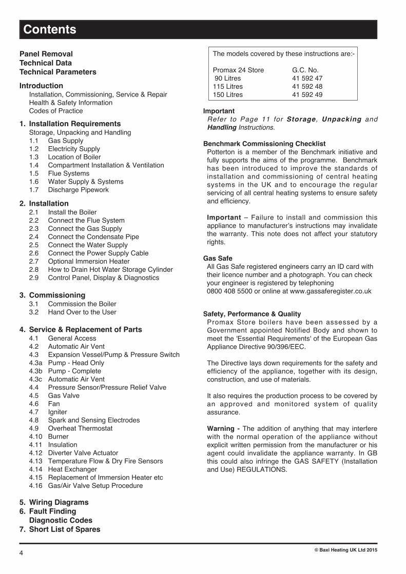
Panel RemovalTechnical DataTechnical Parameters
Introduction Installation, Commissioning, Service & Repair Health & Safety Information Codes of Practice
1. Installation Requirements Storage, Unpacking and Handling 1.1 Gas Supply 1.2 Electricity Supply 1.3 Location of Boiler 1.4 Compartment Installation & Ventilation 1.5 Flue Systems 1.6 Water Supply & Systems 1.7 Discharge Pipework
2. Installation 2.1 Install the Boiler 2.2 Connect the Flue System 2.3 Connect the Gas Supply 2.4 Connect the Condensate Pipe 2.5 Connect the Water Supply 2.6 Connect the Power Supply Cable 2.7 Optional Immersion Heater 2.8 How to Drain Hot Water Storage Cylinder 2.9 Control Panel, Display & Diagnostics
3. Commissioning 3.1 Commission the Boiler 3.2 Hand Over to the User
4. Service & Replacement of Parts 4.1 General Access 4.2 Automatic Air Vent 4.3 Expansion Vessel/Pump & Pressure Switch 4.3a Pump - Head Only 4.3b Pump - Complete 4.3c Automatic Air Vent 4.4 Pressure Sensor/Pressure Relief Valve 4.5 Gas Valve 4.6 Fan 4.7 Igniter 4.8 Spark and Sensing Electrodes 4.9 Overheat Thermostat 4.10 Burner 4.11 Insulation 4.12 Diverter Valve Actuator 4.13 Temperature Flow & Dry Fire Sensors 4.14 Heat Exchanger 4.15 Replacement of Immersion Heater etc 4.16 Gas/Air Valve Setup Procedure
5. Wiring Diagrams6. Fault Finding Diagnostic Codes7. Short List of Spares
The models covered by these instructions are:-
Promax 24 Store G.C. No. 90 Litres 41 592 47 115 Litres 41 592 48 150 Litres 41 592 49
ImportantRefer to Page 11 for Storage, Unpacking andHandling Instructions.
Benchmark Commissioning ChecklistPotterton is a member of the Benchmark initiative andfully supports the aims of the programme. Benchmarkhas been introduced to improve the standards ofinstallation and commissioning of central heatingsystems in the UK and to encourage the regularservicing of all central heating systems to ensure safetyand efficiency.
Important – Failure to install and commission thisappliance to manufacturer�s instructions may invalidatethe warranty. This note does not affect your statutoryrights.
Gas SafeAll Gas Safe registered engineers carry an ID card withtheir licence number and a photograph. You can checkyour engineer is registered by telephoning 0800 408 5500 or online at www.gassaferegister.co.uk
Safety, Performance & QualityPromax Store boilers have been assessed by aGovernment appointed Notified Body and shown tomeet the 'Essential Requirements' of the European GasAppliance Directive 90/396/EEC.
The Directive lays down requirements for the safety andefficiency of the appliance, together with its design,construction, and use of materials.
It also requires the production process to be covered byan approved and monitored system of qualityassurance.
Warning - The addition of anything that may interferewith the normal operation of the appliance withoutexplicit written permission from the manufacturer or hisagent could invalidate the appliance warranty. In GBthis could also infringe the GAS SAFETY (Installationand Use) REGULATIONS.

Panel Removal
MA
X00
06B
Bottom Section
Union Nuts(remain withBottom Section)
DHW Sensor Pocket(310mm deep)
Top & Bottom Section
Handholds(Underneath boiler)
Lifting andplumbing
accesseach side
Mains powersupply and
Immersion Heatercable entry holes
Pull up and away Top Panel2
4
3
Pull forward Front Panel at the bottom and lift off
General AccessPlumbing Access
1
Pull forward Bottom Panel
Unscrew Upper Panel at the bottom and pull away
Retaining Screws (Upper Panel)
Condensateoutlet hole
Top Section
Lift Heat Engine onto Cylinder. Ensure the rollers engage into location channels.Tilt and slide until front location pegs drop into position on the cylinder.
Location Peg
Location Channel
Rollers
Fig. 1
Important: Refer to Page 11 for Storage, Unpacking and Handling Instructions.
5© Baxi Heating UK Ltd 2015

Technical Data
Unless indicated, data shown relevant to all models 90 litre 115 litre 150 litre
Classifications Appliance category CAT I2H Flue Type C13 - C33 - C53 (as supplied) NOx Class 5 Cylinder Insulation CFC, HCFC = 0%
Input Qn Hs (hot water/central heating) - gross 7.8 - 27.4 kWOutput to CH Pn (non-condensing) 6.8 - 24.0 kWOutput to CH Pnc (condensing) 7.6 - 25.9 kW
Inlet pressure 20 mbarGas rate (after 10 mins.) 2.6 m3/hr max.
Gas control differential (offset) -3 Pa to - 8 Pa (- 0.03 to - 0.08 mbar)CO (approx average) 70 ppm
Ventilation Requirements: No Compartment Ventilation Required Connections CH Flow & Return 22 mm �Techtite�/compression DHW Inlet & Outlet 22 mm tube end Gas 22 mm compression Temperature/Press. Relief Valve 22 mm compression from tundish. Condensate Outlet Flexible Pipe 500 mm long (fits 21.5 mm PP overflow systems) Inlet Control Group 22 mm compression inlet & outlet
Set reduced pressure 2.5 bar, expansion relief valve set 8.0 bar Filling Loop 15 mm /1/2” union (accessible behind lower front panel)
Secondary Expansion Vessel 12 litre, pre-charge 2.5 - 2.7 bar (supplied separately)Automatic bypass Built in
Pressure loss warning Gauge on faciaBuilt in programmer 2-channel, pre-programmed, battery back-up, separate times for HW & CH, advance button, CH off selectorExternal programmer Built-in room thermostat Dedicated connectors on user terminal blockBuilt in frost protection Boiler protected below 5 °C
Optional Immersion Heater Heatrae �Mega�. 3 kW at 240V, Advantica Approved
Electricity supply 230v ~ 3A fused supply,Power Consumption (maximum) 126W
Working pressures Primary 0.9 - 2.5 bar DHW 1.0 - 2.5 bar Mains Supply 1.0 - 16.0 bar Pressure Relief Valve (Primary) 3.0 bar Temperature/Press. Relief Valve Pre-set 95 °C, 10.0 bar opening
DHW temperature 30 °C to 60 °CDHW flow rate (Practical maximum assuming suitable mains supply) 25 l/m max. 25 l/m max. 25 l/m max.
Weights Lift Weight Heat Engine 45 kg Cylinder 37 kg 41 kg 49 kg Full Weight 171 kg 202 kg 246 kg
Cylinder Maximum Mains Pressure 1.6MPa (16 bar)Operational Operating Pressure/PRV 0.25MPa (2.5 bar)Summary Maximum Design Pressure 0.8 MPa (8 bar) Expansion Vessel Charge Pressure 0.25MPa (2.5 bar) Expansion Relief Valve Setting 0.8MPa (8 bar) T & P Relief Valve Setting 90 - 95°C/1.0MPa (10 bar) Pressure Drop (Primary Coil) 0.02MPa (0.2 bar)
Cylinder Standing Heat Loss 90L 0.93kW/24hrs 115L 1.04kW/24hrs 150L 1.39kW/24hrs
6 © Baxi Heating UK Ltd 2015

Technical Parameters
Technical parameters for boiler combination heaters
Condensing boiler
90Potterton Promax 24 Store ErP
Rated heat output
Seasonal space heating energy efficiency
Auxiliary electricity consumption
Other items
115 150
Low-temperature boiler(1)
B1 boiler
Cogeneration space heater
Combination heater
Prated kW
Useful heat output at rated heat output
and high temperature regime(2)
P4 kW
Useful heat output at 30% of rated heat
output and low temperature regime(1)
P1 kW
s %
Useful efficiency at rated heat output and
high temperature regime(2)
4 %
Useful efficiency at 30% of rated heat
output and low temperature regime(1)
1 %
Full load elmax kW
Part load elmin kW
Standby mode PSB kW
Standby heat loss Pstby kW
Ignition burner power consumption Pign kW
Annual energy consumption QHE kWh
GJ
Sound power level, indoors LWA dB
Emissions of nitrogen oxides NOX
Daily electricity consumption
Domestic hot water parameters
Declared load profile
Water heating energy efficiency
Qelec kWh
Annual electricity consumption AEC kWh
wh %
Daily fuel consumption Qfuel kWh
Annual fuel consumption AFC GJ
(1) Low temperature means for condensing boilers 30°C, for low temperature boilers 37°C and for other heaters 50°C
return temperature (at heater inlet).
(2) High temperature regime means 60°C return temperature at heater inlet and 80°C feed temperature at heater outlet.
SSee
The back cover for contact details.
mg/kWh
Yes Yes Yes
Yes Yes Yes
No No No
No No No
No No No
24 24 24
24.0 24.0 24.0
8.0 8.0 8.0
92 92 92
87.2 87.2 87.2
96.8 96.8 96.8
0.049 0.049 0.049
0.019 0.019 0.019
0.003 0.003 0.003
0.040 0.040 0.040
- - -
20870 20870 2087075 75 75
18 18 18
XL XL XL
0.192 0.224 0.246
42 49 54
90 92 77
21.234 20.621 25.856
16 16 19
57 57 57
7© Baxi Heating UK Ltd 2015

MA
X00
07A
Note:At these minimum clearances abovethe appliance, adequate workingaccess MUST be provided.
Note:Cupboardintendedto provideaccess.
Removable Top Panel
Typical Cupboard Installationwith twin vertical air/flue pipes
Typical Bulkhead Installationwith rearwards horizontal concentric flue
250min
Removable Top Panel450min
250min 650 max
DoorFrame
400 mmRecommended
*
*
* 400 mmRecommended*
ConcentricFlue
Ø80Air
Tube
NoClearancerequired
Ø80FlueTube
145145
Side Flue
Rear Flue(300 min.)
All dimensionsin mm
600
TwinFlue
MA
X00
08B
Ø100 Air Tube&
Ø60 Flue Tube
C/L
Inner Wall
Outer Wall
Inner Wall
Outer Wall
C/L
550
Fig. 2
Fig. 3
Promax Store
Promax Store
Promax Store1544 mm
150 LitreModel
115 LitreModel
90 LitreModel
1344 mm
1264 mm
25 mm 25 mm
25 mm25 mm
25 mm25 mm
8 © Baxi Heating UK Ltd 2015

Introduction
Important - Installation, Commissioning, Service &Repair
This appliance must be installed in accordance with themanufacturer�s instructions and the regulations in force.Read the instructions fully before installing or usingthe appliance.
In GB this must be carried out by a competent person asstated in the Gas Safety (Installation & Use) Regulations.
Definition of competence: A person who works for a GasSafe registered company and holding current certificatesin the relevant ACS modules, is deemed competent.
In IE this must be carried out by a competent person asstated in I.S. 813. "Domestic Gas Installations".
Read the instructions fully before installing or lighting theboiler.
Promax 24 Store is a f loor standing condensingcombination boiler which incorporates a hot water storeto provide domestic hot water (DHW) and central heating(CH). The DHW temperature is user adjustable (e.g. forsummer/winter operation). Operation is automatic and thefully modulating pre-mixed burner ensures that gas isburned cleanly and efficiently within the condensing heatexchanger. An advanced burner control includes flamemonitoring, pressure monitoring and other safetyfeatures, plus status and diagnostic displays which arelarge and easy to read.
Installation of this boiler as an unvented hot water systemfalls within the scope of the Building Regulations 1995(Part G). These require that installation of an �unvented�system shall be notified to the local authority BuildingControl Department; also that the work must be carriedout by a competent person as defined in the ApprovedDocument G3. The above requirements do not apply ifhot water is obtained via an open vented feed tank.
Samples of the Promax Store gas boilers have beenexamined by DVGW Technologies Limited, a EU NotifiedBody. The range is certified to comply with the essentialrequirements of the Gas Appliance Directive 90/396/EEC,the Low Voltage Directive 72/23/EEC and showscompliance with the Electro Magnetic CompatibilityDirective 89/336/EEC, the Boiler Efficiency Directive92/42/EEC and are therefore permitted to carry the CEMark.
Operation
The boiler control works on the principle of “hot waterpriority” so the central heating output may betemporarily delayed if the hot water temperaturedrops below the selected temperature e.g. afterdrawing a hot bath. The selected temperature isuser adjustable in the range 45° to 65 °C
To suit conventional radiator based central heatingsystems, the boiler will normally provide a flowtemperature of around 80 °C. The boiler controlautomatically responds to lower central heating loadsby reducing the boiler output (which saves wastefulon-off cycling).
This boiler must be installed into a sealed(pressurised) primary system.
Provision is made for fitting both room and frostthermostats if required. Note: The boiler has its ownin-built frost protection which will seek to prevent theboiler temperature dropping below 5 °C
For summer operation the user can switch off thecentral heating at the control panel.
Visible Pluming
The efficient condensing operation of Promax Storewill naturally cause condensate to form in the fluepipe and pluming of the condensing gases will bevisible during all but the most favourable atmosphericconditions. In installations with long flue runs, somecondensate may be discharged from the terminal.The flue terminal must, therefore, be sited to avoidnuisance from either phenomenon.
Delivery & Kits Available
Promax Store boilers are delivered in three packages(1) the heat engine and unvented accessory kit, (2)the hot water cylinder and (3) the flue kit. The flue kitmust be ordered/specified additionally to the boiler.
Health and Safety Information for the Installerand Service Engineer
Under the Consumer Protection Act 1987 and Section6 of the Health and Safety at Work Act 1974, we arerequired to provide information on substanceshazardous to health.This boiler does not contain substances harmful tohealth; it does not contain asbestos. Small quantitiesof adhesives and sealants used in the product arecured and present no known hazards.
Checklist of supplied components:
Cold water control pack including:Expansion VesselExpansion Vessel BracketExpansion Vessel Braided Hose with SealsPressure Reducing Valve (2.5 bar)Pressure Relief Valve (8 bar)Nuts and OlivesTundishBracket
9© Baxi Heating UK Ltd 2015
CondensateTrap
3 WayDiverter Valve
Flow Sensor
CombustionAnalyser
Test Point Flue Air
AutomaticBypass
Primary Expansion Vessel
AutomaticAir Vent
GasValve
Isolation Valve
IsolationValve
Pump
PrimaryReliefValve
Heat Exchanger
Combination Valve
TundishCross/CheckValve
Tundish
Gas
Gas Cock
D.H.W. Sensor
Hot WaterCylinder
CHReturn
CHFlow
Schematic Diagram
Filling Loop
DoubleCheckValve
DHW
Cold Main
Stopcock
Balanced Cold Feed to Shower
Pressure Relief Valve
SecondaryExpansionVessel
FanA B
T.P.R.V.
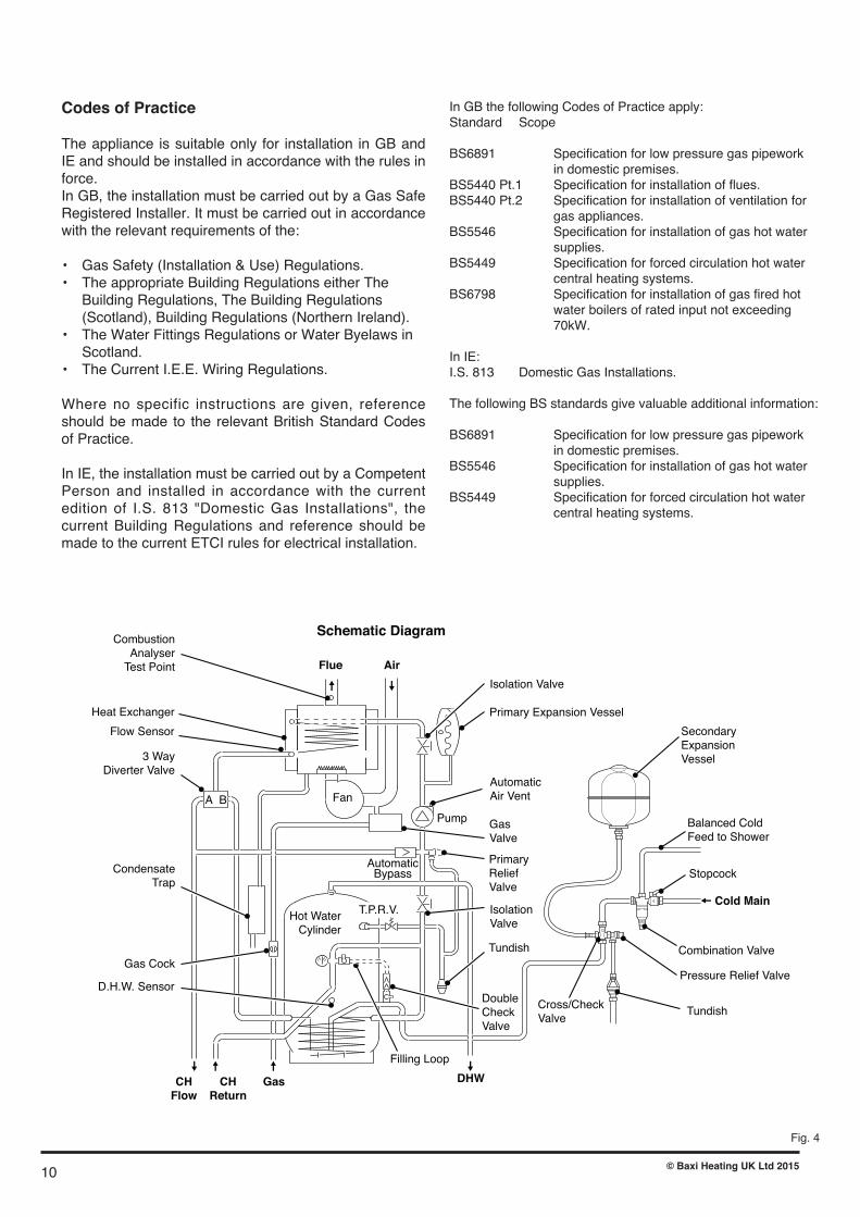
Codes of Practice
The appliance is suitable only for installation in GB andIE and should be installed in accordance with the rules inforce.In GB, the installation must be carried out by a Gas SafeRegistered Installer. It must be carried out in accordancewith the relevant requirements of the:
• Gas Safety (Installation & Use) Regulations.• The appropriate Building Regulations either The Building Regulations, The Building Regulations (Scotland), Building Regulations (Northern Ireland).
• The Water Fittings Regulations or Water Byelaws in Scotland.
• The Current I.E.E. Wiring Regulations.
Where no specific instructions are given, referenceshould be made to the relevant British Standard Codesof Practice.
In IE, the installation must be carried out by a CompetentPerson and installed in accordance with the currentedition of I.S. 813 "Domestic Gas Installations", thecurrent Building Regulations and reference should bemade to the current ETCI rules for electrical installation.
Fig. 4
In GB the following Codes of Practice apply:Standard Scope
BS6891 Specification for low pressure gas pipework in domestic premises.
BS5440 Pt.1 Specification for installation of flues.BS5440 Pt.2 Specification for installation of ventilation for gas appliances.
BS5546 Specification for installation of gas hot water supplies.
BS5449 Specification for forced circulation hot water central heating systems.
BS6798 Specification for installation of gas fired hot water boilers of rated input not exceeding 70kW.
In IE:I.S. 813 Domestic Gas Installations.
The following BS standards give valuable additional information:
BS6891 Specification for low pressure gas pipework in domestic premises.
BS5546 Specification for installation of gas hot water supplies.
BS5449 Specification for forced circulation hot water central heating systems.
10 © Baxi Heating UK Ltd 2015

1. Installation Requirements
Storage, Unpacking & Handling
This boiler is delivered in two sections for safety andease of handling. Store both the Top (heat engine)and the Bottom (cylinder) under cover in dry conditions.
Remove the Promax 24 Store unvented Accessory Kitfrom above the heat engine to reduce lift weight. (Thefront and top panels can also be removed if required -see Fig. 1).
Handholds are provided at the top rear of the heatengine and will assist with removing it from thetransport tray. Handholds are provided at both sidesand underneath the cylinder.
Use a handling device e.g. sack truck, to manuallymove either section over long distances. Trucking mustbe done from the rear. Take particular care to avoiddamaging outer panels or programmer.
These items should be lifted and handled by twopeople. Stooping should be avoided and protectiveclothing worn when necessary. Carrying and liftingequipment should be used as required for moving Topand Bottom to where they will be assembled andinstalled..
Determine beforehand whether the Top and Bottomshould be assembled to enable the complete unit to bemoved into position, or whether to fit the cylinder andthen lift the heat engine into position.
The Top has 2 downward facing dowel pins whichprovide accurate location on to the cylinder. Take careto avoid trapping hands and fingers during assembly.
Take great care when manoeuvring the boiler into itsfinal location and avoid twisting movements of thebody. Do not attempt to carry the complete boileras the Top is only dowelled to the Bottom.
Dispose of packaging in accordance withenvironmental guidelines.
1.1 Gas Supply
Entry holes are provided in the base and via knockoutsin the side panels.
This boiler requires a natural gas supply of 2.6 cubicmetres per hour. A 22 mm gas inlet connection isprovided at the front and gas supply pipework of notless than 22 mm diameter should be run to the boiler.The meter and supply pipes must be capable ofdelivering this quantity of gas in addition to the demand
from any other appliances in the house and must begoverned at the meter.
The gas installation should be in accordance with therelevant standards. In GB this is BS 6891. In IE this isthe current edit ion of I.S. 813 "Domestic GasInstallations".
The whole of the gas installation must be checked forsoundness and purged in accordance with, in GB, BS6891 and in IE, I.S. 813 “Domestic Gas Installations”.
1.2 Electricity Supply
The boiler requires a 230V ~ 50Hz single-phase 3Afused electrical supply. External wiring must be correctlyearthed, polarised and in accordance with relevantregulations/rules. In GB this is the current I.E.E. WiringRegulations. In IE reference should be made to thecurrent edition of the ETCI rules.
Detailed wiring instructions are given in Section 5.
WARNING: THIS BOILER MUST BE EARTHED
In the event of an electrical fault after installation of theboiler, preliminary electrical systems checks must becarried out i.e. Earth Continuity, Short Circuit, Polarityand Resistance to Earth.
1.3 Location of Boiler
The boiler must not be sited outside or in any outhousewhere it could be exposed to the weather.
The boiler must be installed on a flat floor capable ofsupporting the weight of the unit when full of water – upto 250 kg for the 150 litre model.
It should be sited to minimise the length of flue and toavoid long hot water pipe runs.
The extended flueing capability enables the boiler to besited well away from an outside wall, thus installation ina first floor cupboard or compartment, basement, utilityroom or kitchen are all feasible locations.
The location chosen must permit the provision of asatisfactory external flue termination. The location mustalso provide adequate space for servicing and aircirculation.
11© Baxi Heating UK Ltd 2015

VENTILATION
1. Where the appliance is installed in a cupboard or compartment, no air vents are required.
2. BS 5440: Part 2 refers to room sealed appliances installed in compartments. The appliance will run sufficiently cool without ventilation.
1.5 Flueing
This is a “room sealed” condensing boiler. Fluesystems are supplied in kits, or components can beordered individually from Potterton. Only Promax Storeflue components (which are designed for condensingoperation) can be used.
Flue Systems
All boilers are supplied to accept either the concentrichorizontal flue system or the Promax 80 mm dia. twinflue system, however several flue system options areavailable.
Each system is room sealed and offers a choice offlue type and termination method, (pages 15 & 16).
• Concentric balanced flue with horizontal terminal• Twin flue with vertical terminal *
Flue extension lengths and bends should bepurchased separately, as required.
* These terminals must be ordered/specified separately.
If floor settlement is likely due to the weight of theboiler, ensure that both the flueing and pipeworklayouts safely provide sufficient flexibility.
If the boiler is to be fitted in a room containing a bathor shower reference must be made to the relevantrequirements.
In GB this is the current I.E.E. Wiring Regulations andBuilding Regulations.
In IE reference should be made to the current editionof I.S. 813 "Domestic Gas Installations" and thecurrent ETCI rules.
1.4 Compartment Installation and Ventilation
General guidance for cupboard/compartmentinstallations, including airing cupboards, is contained inBS 6798. Specific requirements for Promax 24 Storeare given below.
1. The compartment should be a fixed rigid structure large enough to allow it and the boiler to be inspected and serviced. A minimum width between the door jambs of 570 mm must be provided.
2. Minimum clearances are indicated in Fig.3. A full height compartment door must be at least 15 mm from the front of the boiler and provide 200 mm access height above the boiler.
3. Householders should be discouraged from storing clothes etc. on the boiler itself. A removable shelf at least 75 mm above the boiler is acceptable.
4. The internal surfaces of an understairs cupboard must be lined with non-combustible materials. The door shall have a BS 476 fire resistance of not less than 0.5 hour.
12 © Baxi Heating UK Ltd 2015

General Requirements for Horizontal FlueTerminations
Detailed recommendations for flueing are given inBS5440: Part 1. The following notes give generalguidance. The horizontal balanced flue terminal mustbe installed so that it is exposed to external air,preferably on a clear expanse of wall. Acceptablepositions are indicated in Fig. 5. Avoid positions wherethe terminal is adjacent to projections; particularlyimmediately under a balcony, inside a re-entrantposition, or immediately adjacent to a drain pipe. If theboiler is fitted under a ventilator or opening window, theterminal must be at least 300 mm from any part of thewindow or ventilator and in accordance with BS5440:Part 1.
The flue pipe must not be closer than 25 mm tocombustible material. Additional clearance must beprovided when passing the flue through timber walls.Advice on gas installations in timber framed buildings iscontained in IGE technical publication IGE/UP/7available from the Institution of Gas Engineers, 21Portland Place, London W1N 3AF.
Guidance notes for Flue Installation
Read these Installation Instructions before installingthe boiler. Before starting an installation, check that thecorrect flue kit has been supplied with the boiler.
Detailed recommendations for flue installations are givenin BS 5440:1: 2000. The following notes are for generalguidance only.
a) The flue system must be constructed using only Promax approved components.
b) It is important that the position of the terminal allows free passage of air across it at all times.
c) It is ESSENTIAL TO ENSURE that products of combustion discharging from the terminal cannot re- enter the building, or any other adjacent building, through ventilators, windows, doors, other sources of natural air infiltration, or forced ventilation / air conditioning.
d) The minimum permissible dimensions between the flue terminal and obstructions and ventilation openings are specified in the table on page 14 of these instructions.
e) If the flue terminal discharges into a pathway or passageway check that combustion products will not cause nuisance and that the terminal will not obstruct the passageway.
f) Where terminals are fitted within 850 mm of a plastic or painted gutter, or 450 mm of painted eaves, an
aluminium shield at least 750 mm long must be fitted to the underside of the plastic or painted surface.
g) Where installation will be in an unusual location, special procedures may be necessary. BS 6798 gives detailed guidance on this aspect.
h) As the Promax Store is a condensing boiler the flue duct must have a fall back to the boiler of at least 1.5°.
j) The efficient condensing operation of the Promax Store will naturally give rise to condensation in the flue gases and pluming will occur in all but the most favourable atmospheric conditions. Some condensate may also be discharged from the terminal. The terminal must, therefore, be sited to avoid nuisance from either phenomenon.
k) Where the lowest part of the terminal is less than 2 m above the level of any ground, balcony, flat roof or place to which people have access, the terminal must be protected by a guard of durable material.
13© Baxi Heating UK Ltd 2015

N
I
I
G
F
M
I
AA
F
H
J,K
DE
H
Likely flue positions requiring a flue terminal guard
C
RA
I
J,K
I
L
S
B
T
U
Top View
TopView
ConcentricTerminalAssembly
RearConcentric
Flue
Side ConcentricFlue
300 min. 300 min.
MA
X00
27A
PropertyBoundary Line
Fig. 5
Terminal Position with Minimum Distance (mm)For IE, refer to I.S. 813 "Domestic Gas Installation".
Fanned Draught Balanced Flue
Note: The distance from a fanned draught appliance terminal installedparallel to a boundary may not be less than 300 mm in accordancewith the diagram on the left.
1 In addition, the terminal should be no nearer than 150 mm to anopening in the building fabric formed for the purpose of accommodating abuilt-in element such as a window frame.2 Only ONE 25mm clearance is allowed per installation. If one of thedimensions D,E,F,G or H is 25mm then the remainder MUST be asshown in brackets, in accordance with BS 5440 Pt. 1.
OpeningWindow or Door
150mmMIN.
IMPORTANT: If fitting a Plume
Displacement Flue Kit, the air inlet
must be a minimum of 100mm
from any opening windows or
doors
PlumeDisplacement Kit
Air Inlet
IMPORTANT:• Under car ports we recommend the use of the plume
displacement kit.• The terminal position must ensure the safe and
nuisance - free dispersal of combustion products.
Terminal Position with Minimum Distance (Fig. 18) (mm)A1 Directly below an opening, air brick, opening windows, etc. 300B1 Above an opening, air brick, opening window etc. 300C1 Horizontally to an opening, air brick, opening window etc. 300D2 Below gutters, soil pipes or drain pipes. 25 (75)E2 Below eaves. 25 (200)F2 Below balconies or car port roof. 25 (200)G2 From a vertical drain pipe or soil pipe. 25 (150)H2 From an internal or external corner. 25 (300)I Above ground, roof or balcony level. 300J From a surface or boundary line facing a terminal. 600K From a terminal facing a terminal (Horizontal flue). 1200
From a terminal facing a terminal (Vertical flue). 600L From an opening in carport (e.g. door, window) into
the dwelling. 1200M Vertically from a terminal on the same wall. 1500N Horizontally from a terminal on the same wall. 300R From adjacent wall to flue (vertical only). 300S From an adjacent opening window (vertical only). 1000T Adjacent to windows or openings on pitched and flat roofs 600U Below windows or openings on pitched roofs 2000
14 © Baxi Heating UK Ltd 2015

Flue Options
1. The Promax 24 Store can be fitted with fluesystems as illustrated.
2. Maximum permissible equivalent flue lengthsare:-10 metres (60/100 system - vertical & horizontal)20 metres (80/125 system - vertical & horizontal)15 metres (80/80 twin pipe)
3. Any additional “in line” bends in the fluesystem must be taken into consideration. Their equivalent lengths are:-
Concentric Pipes:45° bend 0.5 metres93° bend 1.0 metres
Twin Flue Pipe45° bend 0.25 metres91.5° bend 0.50 metres
The elbow attached to the boiler is not includedin any equivalent length calculations
4. The illustrations opposite show examples ofpermissible flue systems.
NOTE: Flue length is measured from point Xto Y as shown.
IMPORTANT: All flue systems must besecurely supported at least once everymetre. Suitable pipe supports are availableas accessories.
HorizontalFlues
Y
X
Plume Displacement Kit 60 /100 Ø
1M Extensions, 45° & 93° bends arealso available
NOTE: Horizontal flue pipes should always be installed with at least a1.5° fall from the terminal to allow condensate to run back to the boiler.
Y
X
This bend is equivalent to1 metre
Total equivalent length(up to 10m) =
A+B+C+2x90°Bends
B
AC
This bend is equivalentto 1 metre
15© Baxi Heating UK Ltd 2015

Fig. 5a
Fig. 5c
315mm
500mm
Flue Dimensions
The standard horizontal flue kit allows for flue lengthsbetween 100mm and 685mm from elbow to terminal (Fig. 5a).
The maximum permissible equivalent flue length is:10 metres (60/100 system)
Flue Trim
1. The rubber flue trim supplied may be fitted to eitherthe outside wall or on the inner wall of installation.
Terminal Guard (Fig. 5c)
1. When codes of practice dictate the use of terminalguards, they can be obtained from most Plumbers� andBuilders� Merchants.
2. There must be a clearance of at least 50mmbetween any part of the terminal and the guard.
3. When ordering a terminal guard, quote theappliance name and model number.
4. The flue terminal guard should be positionedcentrally over the terminal and fixed as illustrated.
Flue Deflector (Fig. 5b)
1. If required a flue deflector is available from yourPotterton stockist.
2. Push the flue deflector over the terminal end. It maypoint upwards as shown, or up to 45° either way fromvertical. Secure the deflector to the terminal withscrews provided.
Flue Accessories (Fig. 5d)
1. For full details of Flue Accessories (elbows,extensions, clamps etc.) refer to the Flue InstallationGuide supplied in the literature pack.
Flue Deflector
Fig. 5b
Ensure that no part of the white outerchimney duct is visible
© Baxi Heating UK Ltd 2011
G U I D A N C E N OT E S
Flue Accessories & Fitting GuideØ 60/100 Flue SystemsØ 80/125 Flue SystemsØ 80/80 Twin Flue SystemsPlume Displacement Kit (Ø 60/100 Flue Systems)
READ THESE INSTRUCTIONS IN CONJUNCTION WITH THE BOILERINSTALLATION INSTRUCTIONS BEFORE FITTING THE FLUE
Please leave these instructions with the Installation & Servicing Instructions.
IMPORTANT NOTE: This documentwill assist in the correct installation ofthe various flue & chimney systemsdescribed within. However, it is theresponsibility of the installer/Gas Saferegistered commissioning engineer toensure that the flue & chimney systemis fitted safely and in compliance withthe relevant standards and practices inforce in the country of installation.
Fig. 5d
16 © Baxi Heating UK Ltd 2015

1.6 Water Supply
Mains Supply RequirementsIt is essential that the mains supply pressure andavailable flow rate are capable of meeting demand forboth hot and cold water Promax Store is notrecommended for unvented use where the dynamicmains pressure is below 1.0 bar.
Unless consistently high mains pressures are available,it is unlikely that a service pipe of less than 25 mm OD(Blue MDPE) will supply an adequate flow rate.
Plumbing DesignA combination inlet valve group is included with everyPromax Store (packed in the “Accessories” boxsupplied with the Heat Engine). The mains water supplymust be connected via the combination reducing valveand the cross fitting, in that order. Both components areclearly marked with the direction of flow (see Fig. 11page 23).
The cold feed pipe to showers (and other mixer fittingsneeding balanced pressures) must be taken from the22mm blanked outlet port of the combination reducingvalve (or a tee between this and the cross fitting). Thevalve can be sited near where the water mains entersthe dwelling, to assist with providing reduced pressureto all the system.
Cold water draw-offs that do not require a balancedsupply e.g. hose-union or WC cistern, should be teedoff upstream of the combination reducing valve.
A 22mm connection is provided from the hot waterstore. Smaller diameter pipework may be used locallyfor terminal fittings as part of a balanced design.
Thermostatic shower mixers are recommended tooptimise performance; these must be suitable for use atmains pressure. Using flow restrictors will help prolongthe showering time available from smaller capacitystores.
Use in Hard Water AreasIn the UK., water is drawn from diverse sources someof which have high levels of natural hardness. If notdealt with effectively, the scaling associated with hardwaters can adversely affect hot water performance. Asa general guide, if the temporary hardness exceeds 200mg/l, then some form of water treatment device isrequired. The ultimate solution is an ion-exchange (saltregenerated) water softener. In addition to protectingthe Promax heat exchanger against the effects oflimescale, an ion-exchange softener offers users otherbenefits and should be specified with an appropriateflow rate capacity.
Water “conditioning” devices such as those which dosethe incoming water with food grade polyphosphates can
be effective in reducing limescale but require correctsiting and regular replenishment to remain operational.They should generally not be fitted where heat couldimpair their performance. Other types of device caninhibit scale formation but their effectiveness may vary.The manufacturers of any water conditioning deviceshould be consulted regarding its suitability for theapplication and the particular water supply to theinstallation address.
Record the type of condit ioner being used in“Benchmark” Commissioning Checklist.
Treatment of Water Circulating SystemsAll recirculatory water systems will be subject tocorrosion unless an appropriate water treatment isapplied. This means that the efficiency of the system willdeteriorate as corrosion sludge accumulates within thesystem, risking damage to pump and valves, boiler noiseand circulation problems.
When fitting new systems flux will be evident within thesystem, which can lead to damage of systemcomponents.
All systems must be thoroughly drained and flushed out.Using, for example Sentinel X300 or X400 or Fernox F3.They should be used following the flushing agentmanufacturer�s instructions.
System additives - corrosion inhibitors and flushingagents/descalers should comply to BS7593requirements, e.g Sentinel X100 and Fernox MB-1 whichshould be used following the inhibitor manufacturer�sinstructions.
Full instructions are supplied with the products, forfurther information contact Sentinel (0800 389 4670) orFernox (0870 870 0362)
Failure to flush and add inhibitor to the system willinvalidate the appliance warranty.
It is important to check the inhibitor concentration afterinstallation, system modification and at every service inaccordance with the manufacturer�s instructions. (Testkits are available from inhibitor stockists.)
Sealed Primary SystemsThis boiler must be installed into a sealed primarysystem. As a general guide systems of up to 7-9radiators will operate satisfactorily with the 10 litreexpansion vessel built into the boiler.
• Guidance on expansion vessel sizing
These notes explain how to calculate the total expansion vessel volume required, based on the size and the initial cold fill pressure of the system. If the required volume exceeds that of the vessel fitted to the boiler then an additional vessel should be installed, on the return connection from the heating system. The charge pressure of any additional vessel is assumed to be 1.0 bar, the same as the vessel fitted to the boiler.
17© Baxi Heating UK Ltd 2015

If the initial cold fill pressure is 1.0 bar: expansion vessel size = 0.11 x system volume This fill pressure will allow the maximum expansion capacity, though any minor loss of water will result in a rapid pressure drop. An additional expansion vessel is only required if the total system volume exceeds 98 litres.
This includes the 4 litre primary circuit volume within the Promax Store boiler - thus radiator and pipework volume should not exceed 94 litres.
Pipework above boilerAir vents must be fitted at the highest positions on flowand return pipes and at any point where air is likely tocollect.
TRV�s in SystemAn automatic bypass valve is built into the boiler toallow thermostatic radiator valves to be fitted. This canbe switched into or out of circuit as required.
1.7 Discharge Pipework
It is a requirement of Building Regulation G3 that anydischarge from an unvented system is conveyed towhere it is visible, but will not cause danger to personsin or about the building. The tundish and dischargepipes should be fitted in accordance with therequirements and guidance notes of BuildingRegulation G3. The G3 Requirements and Guidancesection 3.9 are reproduced in the following sections.Information Sheet No. 33 available from the BritishBoard of Agrement gives further advice on dischargepipe installation. For discharge pipe arrangements notcovered by G3 Guidance or BBA Info Sheet No.33advice should be sought from either your local BuildingControl Officer or Potterton.
G3 Requirement “...there shall be precautions ... toensure that the hot water discharged from safetydevices is safely conveyed to where it is visible but willnot cause danger to persons in or about the building.”
G3 Guidance SECTION 3.9The discharge pipe (D1) from the vessel up to andincluding the tundish is generally supplied by themanufacturer of the hot water storage system. Whereotherwise, the installation should include the dischargepipe(s) (D1) from the safety device(s). In either casethe tundish should be vertical, located in the samespace as the unvented hot water storage system andbe fitted as close as possible and within 600 mm of thesafety device e.g. the temperature relief valve. Note:The tundish is factory fitted during manufacture ofthe Promax Store. The discharge pipe (D2) from thetundish should terminate in a safe place where there isno risk to persons in the vicinity of the discharge,preferably be of metal and:
a.be at least one pipe size larger than the nominaloutlet size of the safety device unless its totalequivalent hydraulic resistance exceeds that of astraight pipe 9m long i.e. discharge pipes between9m and 18m equivalent resistance length shouldbe at least two sizes larger than the nominalOutlet size of the safety device, between 18 and27m at least 3 sizes larger, and so on. Bends mustbe taken into account in calculating the flowresistance. Refer to Fig. 8, Table 1 and the workedexample.
An alternative approach for sizing discharge pipeswould be to follow BS 6700:1987 Specification for design installation, testing and maintenance ofservices supplying water for domestic use withinbuildings and their curtilages. Appendix E. section E2and table 21.
b.have a vertical section of pipe at least 300 mm long, below the tundish before any elbows or bends in the pipework.
c.be installed with a continuous fall.
d.have discharges visible at both the tundish and the final point of discharge, but where this is not possible or practical, there should be clear visibility at one or other of these locations. Examples of acceptable discharge arrangements are:
i. ideally below a fixed grating and above the water seal in a trapped gully.
ii. downward discharges at low level; i.e. up to 100mm above external surfaces such as car parks, hard standings, grassed areas etc. are acceptable providing that where children may play or otherwise come into contact with discharges a wire cage or similar guard is positioned to prevent contact, whilst maintaining visibility.
iii. discharges at high level; e.g. into a metal hopper and metal down pipe with the end of the discharge pipe clearly visible (tundish visible or not) or onto a roof capable of withstanding high temperature discharges of water and 3m from any plastic guttering system that would collect such discharges (tundish visible).
iv. where a single pipe serves a number of discharges, such as in blocks of flats, the number served should be limited to not more than 6 systems so that any installation discharging can be traced reasonably easily. The single common discharge pipe should be at least one pipe size larger than the largest individual discharge pipe (D2) to be connected. If unvented hot water storage systems are installed where discharges from safety devices
18 © Baxi Heating UK Ltd 2015

19
Fig. 8
Valve Minimum Minimum Maximum Resistanceoutlet discharge discharge resistance created bysize pipe D1 pipe D2 allowed, each elbow from expressed or bend tundish as a length of straight pipe (i.e. no elbows or bends)
22 mm up to 9 m 0.8 mG1/2 15 mm 28 mm up to 18 m 1.0 m 35 mm up to 27 m 1.4 m
28 mm up to 9 m 1.0 mG3/4 22 mm 35 mm up to 18 m 1.4 m 42 mm up to 27 m 1.7 m
35 mm up to 9 m 1.4 mG1 28 mm 42 mm up to 18 m 1.7 m 54 mm up to 27 m 2.4 m
Table 1. Sizing of copper discharge pipe (D2) for common temperaturerelief valve outlet sizes. Note: shaded area is reproduced forcompleteness but does not apply to this boiler.
may not be apparent i.e. in dwellings occupied by blind, infirm or disabled people, consideration should be given to the installation of an electronically operated device to warn when discharge takes place.
Note: The discharge will consist of scalding water and steam. Asphalt, roofing felt and non-metallic rainwater goods may be damaged by such discharges.
Worked example of discharge pipe sizingThe example below is for a G1/2 temperaturerelief valve with a discharge pipe (D2) having 4No. 28mm elbows and length of 7 m from thetundish to the point of discharge.
From Table 1:Maximum resistance allowed for a straight lengthof 22mm copper discharge pipe (D2) from aG1/2 temperature relief valve is 9.0 m.
Subtract the resistance for 4 No. 22 mm elbowsat 0.8m each = 3.2 m.
Therefore the permitted length equates to: 5.8 m.
5.8 m is less than the actual length of 7 mtherefore calculate the next largest size.
Maximum resistance allowed for a straight lengthof 28 mm pipe (D2) from a G1/2 temperaturerelief valves equates to 18 m.
Subtract the resistance of 4 No. 28 mm elbowsat 1.0 m each - 4.0 m.
Therefore the maximum permitted lengthequates to: 14 m.
As the actual length is 7 m, a 28 mm min. (D2)copper pipe will be satisfactory.
Warnings• Under No circumstances should the factory fitted Temperature/Pressure Relief Valve be removed other than by Authorised Potterton personnel. To do so will invalidate any warranty or claim.
• The cold water Inlet Control Group must be fitted to the mains water supply to the Promax Store when it is operated as an unvented system.
• Control and safety valves MUST NOT be tampered with.
• The discharge pipe MUST NOT be blocked or used for any other purpose.
• The tundish must not be removed but can be sited outside the RH panel using the opening provided.
• Electrical components must not be sited near the tundish.
© Baxi Heating UK Ltd 2015
300mmminimum
Safety device(e.g. Temperature
relief valve) Metal discharge pipe (D1) from Temperature relief valve to tundish
Tundish
Discharge belowfixed grating
(Building Regulation G3 section 3.61 gives
alternative points of discharge)
Fixed grating
Trapped gully
Discharge pipe (D2 from tundish,with continuous fall. See Building
Regulation G3 section 3.56,Table 4 and worked example)
600mm maximum
Typical Discharge Pipe Arrangement

20
MA
X00
21B
Outline of base plateOutline of front panels
Double arrows are from rear of boiler
70 43 119 122 35 60 54
512
514
536
560
572
544
507
DHWTPRVDischarge
ColdFeed
Gas
Condensate
39
567
Dimensions are approximateAll pipes are 22mm
C/H Flow
AlternateC/H Flow orCondensate
Outline of insulation
46
C/H Return
550 Overall
600 overall
2. Installation
2.1 Install the boiler
Before starting an installation, check that the correct fluekit and correct capacity cylinder have been supplied.
Important: When soldering plumbing fittings, do notallow flame from blowtorch to come into contact withthe insulating foam or other non-metallic parts.
Guidance on where to locate the boiler is given inSections 1.3 and 1.5. In some instances it will beadvantageous to pre-plumb pipework or to pre-fixterminal, air/flue pipes and duct.
1. Remove top and front panels (see Fig. 1) and carefully set aside.
2. Determine boiler final position. The cutaway in the cylinder base allows pipework to be brought up from below floor level. Use the dimensions below or the template on the reverse of the Installation Guide topre-drill any holes. Pipes must not obstruct service access to the immersion heater (if fitted) or to the condensate trap.
3. Move boiler into position. The need to move as Top and Bottom sections or as a complete assembly will depend on the individual installation. The Top has 4 downward facing dowel pins which provide accurate location on to the cylinder. Take care to avoid trappinghands and fingers during assembly.
4. Apply sealant to cone faces of both 22mm Union Nuts (see Fig. 10). Remove cardboard pipework support. Attach the 15mm x 90° branch pipe joining the two relief valves/tundish.
5. Remove the DHW temperature sensor from the boiler fitting kit and uncoil it.
6. Drop down the boiler facia panel. Identify the electrical connection end of the DHW temperature sensor (�A� in Fig.9b).
7. Connect sensor end �A� to the two-pin connector (green wires) from the control box (Fig.9c).
8. Route the sensor cable behind the cylinder pipes and insert end �B� fully (approx. 310mm) into the cylinder pocket (Fig.9a).
9. Remove small knock-outs as required either side of casing for plumbing access. The handholds in the side panels can also be used. Further access holes allow the condensate to be routed via the LH panel and the DHW to be plumbed via the RH panel.
2.2 Connect the Flue System
1. Install the flue system as shown in accordance with theseinstallation instructions and the flue accessory guide,observing additional instructions supplied with any flueaccessory.
2.3 Connect the Gas Supply (Fig. 9a)
1. Ensure that the gas supply is isolated.2. The gas connection to the boiler is 22 mm. Refer to Section 1.1 for information on the required gas supply. Do not turn the gas supply on at this stage.
Fig. 9
MAX0023C
22mm GasConnection
-
+
PROG
SEL
PROG
SEL
-
C.H. ADVANCE
H.W. TEMP
RESETBURNER LOCK OUTMAINS ON
POWER
+
RWC
GasCock
(0pen)
Fig. 9a
Fig. 9b
Fig. 9c �A�
�A�
�B�
Cylinder Pocket
© Baxi Heating UK Ltd 2015

RWC
Cable Bushing
Gas Cock
Isolating Valve
Condensate Trap
Condensate Outlet (500mm supplied)
Plumbing 'NO GO' Area
Immersion Heater
Domestic Hot Water Sensor
D.H.W. Outlet
D.H.W. Outlet
Pressure Relief Valve (3 bar)
TPR Valve (Temperature & Pressure Relief)
By-pass Valve
Isolating Valve
Tundish
Discharge Pipe
Pressure Gauge
Pipework shown as this NOT SUPPLIED
Filling Loop
Potterton Promax Store150 litre model shown
Mains Cold Inlet CH Return
Gas Inlet
CH Flow MAX0002D
22mm Union Nuts 15mm Branch Pipe
Promax Store
Display
Selector & Reset Switch
CH Control Knob
DHW Control
PCB Enclosure
Gas Valve
Diverter Valve
Manual Air Vent
Flue Outlet
Programmer
Pressure Gauge
Pump
Expansion Vessel
Fan
Flue Sample Point
21
Fig. 10
Component & Connection Identification
© Baxi Heating UK Ltd 2015

22
2.4 Condensate Drain Pipe
Before fitting, fill the condensate trap with water.
Fit the steady bracket (with round hole) for thecondensate trap to the lower pair of holes in the left handcylinder side panel. Snap the C-shaped bracket into thegroove in the condensate connector. Insert thecondensate trap into the steady bracket and fit the C-shaped bracket to the upper pair of holes in the left handcylinder side panel.
Ensure that the washer seal is in place as indicated andtighten the large nut.
The condensate pipe should be run in 21.5/22.0 mmdiameter plastic material suitable for operation at 60° C.Solvent weld PVC overflow is recommended or a PPsystem can be used. Copper tube must not be used. Donot use push-fit plastic pipe.
Use the flexible pipe provided to connect to 21.5mm PVCpipe; alternatively a Marley or Plumb Center elbow canbe used to direct the condensate pipe through the LHside panel (see Fig. 10a). When using the Osma PVCoverflow system, a 3/4 -to-22mm adaptor No. 158 may berequired.
Internal pipework should have a bore diameter no smallerthan 14 mm.External pipework should be kept to a minimum, andhave a bore diameter no smaller than 32 mm.Ideally the condensate pipe should be run internally tothe house soil and vent stack or to a waste pipe.Alternatively, the condensate may be discharged into therainwater system, or a purpose-built soakaway.All connecting drainage pipework must have a fall of atleast 50 mm per metre run. It is recommended that thepipe is insulated if run externally to minimise the effectsof freezing. NOTE: Connection of a condensate pipe to a drain maybe subject to local building regulations.
Manual Air Vent
Using the manual air vent, thoroughly vent air fromtop of the heat exchanger when filling the system tosave time during the boiler commissioning. Note: 1/4”dia. manometer tube fits the manual vent.
Central Heating Pump & System By-pass
The central heating pump is factory fitted and anautomatic system by-pass is provided. The boiler canbe used in systems controlled by thermostatic radiatorvalves (TRVs) but it is essential that the by-passisolating valve is fully open.
The circulating pressure and flowrate available for thecentral heating system is shown opposite with the by-pass in circuit. M
AX0022C
Promax Store
RWC
Fill up the CondensateTrap with water, thenfit to the boiler
CondensateDrain Pipe500mm supplied(suitable for 21.5mm overflow pipe)
Washer Seal
BoilerCondensateConnection
OptionalRoute -DHW
OptionalRoute -Condensate
Lower Nut
Fig. 10a
© Baxi Heating UK Ltd 2015
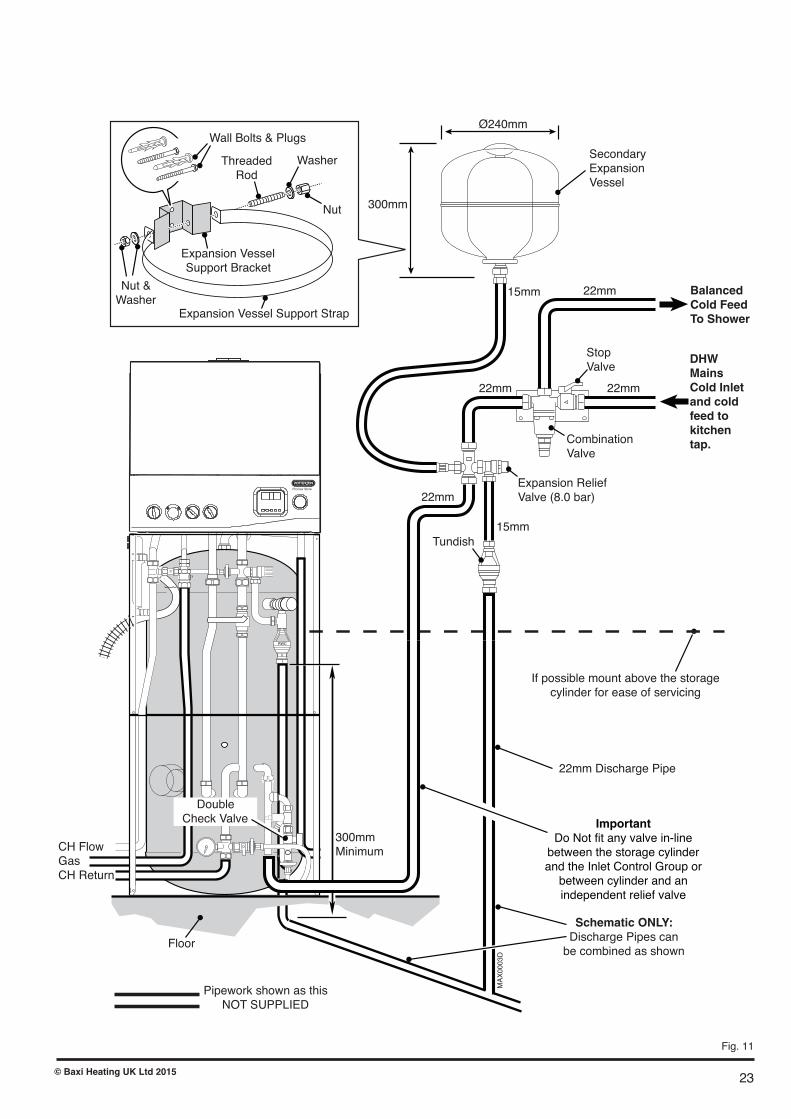
23
If possible mount above the storage cylinder for ease of servicing
22mm Discharge Pipe
300mm Minimum
Expansion Vessel Support Bracket
Expansion Vessel Support Strap
Nut & Washer
Threaded Rod
Washer
Nut
Wall Bolts & Plugs
MAX0003D
Schematic ONLY:Discharge Pipes canbe combined as shown
Floor
CH Flow Gas CH Return
Pipework shown as this NOT SUPPLIED
RWC
ImportantDo Not fit any valve in-linebetween the storage cylinderand the Inlet Control Group orbetween cylinder and anindependent relief valve
Double Check Valve
Promax Store
Secondary Expansion Vessel
Expansion Relief Valve (8.0 bar)
Stop Valve
DHWMainsCold Inletand coldfeed tokitchentap.
Tundish
22mm
22mm 22mm
22mm 15mm
15mm
Combination Valve
BalancedCold Feed To Shower
300mm
Ø240mm
Fig. 11
© Baxi Heating UK Ltd 2015
24
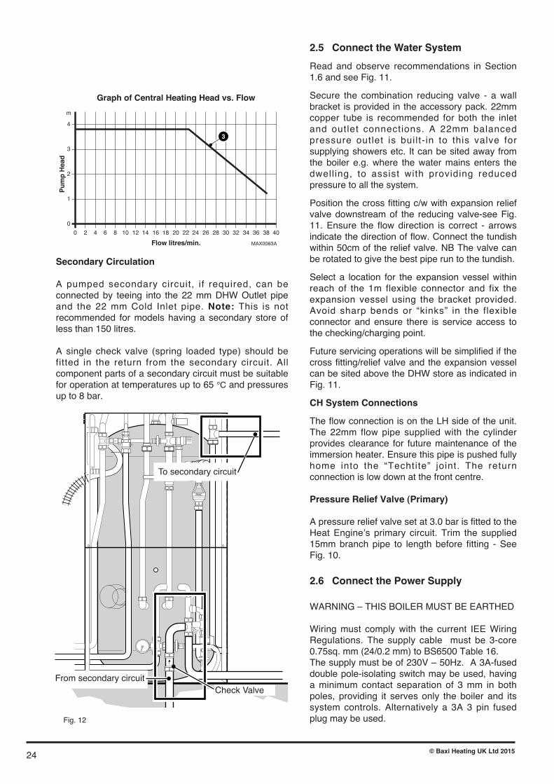
2.5 Connect the Water System
Read and observe recommendations in Section1.6 and see Fig. 11.
Secure the combination reducing valve - a wallbracket is provided in the accessory pack. 22mmcopper tube is recommended for both the inletand outlet connections. A 22mm balancedpressure outlet is built- in to this valve forsupplying showers etc. It can be sited away fromthe boiler e.g. where the water mains enters thedwell ing, to assist with providing reducedpressure to all the system.
Position the cross fitting c/w with expansion reliefvalve downstream of the reducing valve-see Fig.11. Ensure the flow direction is correct - arrowsindicate the direction of flow. Connect the tundishwithin 50cm of the relief valve. NB The valve canbe rotated to give the best pipe run to the tundish.
Select a location for the expansion vessel withinreach of the 1m flexible connector and fix theexpansion vessel using the bracket provided.Avoid sharp bends or “k inks” in the flexibleconnector and ensure there is service access tothe checking/charging point.
Future servicing operations will be simplified if thecross fitting/relief valve and the expansion vesselcan be sited above the DHW store as indicated inFig. 11.
CH System Connections
The flow connection is on the LH side of the unit.The 22mm flow pipe supplied with the cylinderprovides clearance for future maintenance of theimmersion heater. Ensure this pipe is pushed fullyhome into the “Techtite” joint. The returnconnection is low down at the front centre.
Pressure Relief Valve (Primary)
A pressure relief valve set at 3.0 bar is fitted to theHeat Engine�s primary circuit. Trim the supplied15mm branch pipe to length before fitting - SeeFig. 10.
2.6 Connect the Power Supply
WARNING – THIS BOILER MUST BE EARTHED
Wiring must comply with the current IEE WiringRegulations. The supply cable must be 3-core0.75sq. mm (24/0.2 mm) to BS6500 Table 16.The supply must be of 230V – 50Hz. A 3A-fuseddouble pole-isolating switch may be used, havinga minimum contact separation of 3 mm in bothpoles, providing it serves only the boiler and itssystem controls. Alternatively a 3A 3 pin fusedplug may be used.
Secondary Circulation
A pumped secondary circuit, if required, can beconnected by teeing into the 22 mm DHW Outlet pipeand the 22 mm Cold Inlet pipe. Note: This is notrecommended for models having a secondary store ofless than 150 litres.
A single check valve (spring loaded type) should befitted in the return from the secondary circuit. Allcomponent parts of a secondary circuit must be suitablefor operation at temperatures up to 65 °C and pressuresup to 8 bar.
0
0
2 4 6 8 10 12 14 16 18 20 22 24 26 28 30 32 34 36 38 40
1
2
Pu
mp
Hea
d
Flow litres/min.
Graph of Central Heating Head vs. Flow
3
4
m
MAX0063A
3
RWC
From secondary circuit
To secondary circuit
Check Valve
Fig. 12
© Baxi Heating UK Ltd 2015
25
Fig. 13
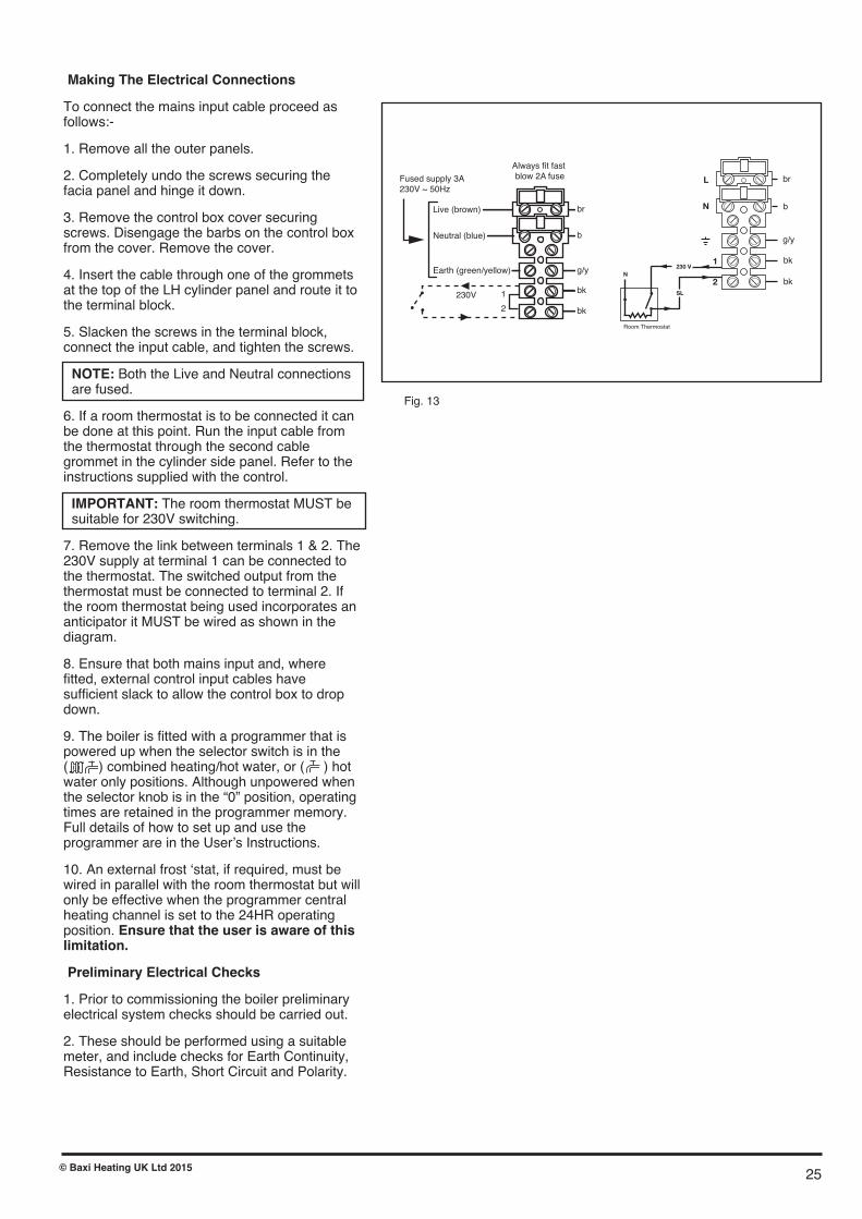
Making The Electrical Connections
To connect the mains input cable proceed asfollows:-
1. Remove all the outer panels.
2. Completely undo the screws securing thefacia panel and hinge it down.
3. Remove the control box cover securingscrews. Disengage the barbs on the control boxfrom the cover. Remove the cover.
4. Insert the cable through one of the grommetsat the top of the LH cylinder panel and route it tothe terminal block.
5. Slacken the screws in the terminal block,connect the input cable, and tighten the screws.
NOTE: Both the Live and Neutral connectionsare fused.
6. If a room thermostat is to be connected it canbe done at this point. Run the input cable fromthe thermostat through the second cablegrommet in the cylinder side panel. Refer to theinstructions supplied with the control.
IMPORTANT: The room thermostat MUST besuitable for 230V switching.
7. Remove the link between terminals 1 & 2. The230V supply at terminal 1 can be connected tothe thermostat. The switched output from thethermostat must be connected to terminal 2. Ifthe room thermostat being used incorporates ananticipator it MUST be wired as shown in thediagram.
8. Ensure that both mains input and, wherefitted, external control input cables havesufficient slack to allow the control box to dropdown.
9. The boiler is fitted with a programmer that ispowered up when the selector switch is in the( ) combined heating/hot water, or ( ) hotwater only positions. Although unpowered whenthe selector knob is in the “0” position, operatingtimes are retained in the programmer memory.Full details of how to set up and use theprogrammer are in the User�s Instructions.
10. An external frost �stat, if required, must bewired in parallel with the room thermostat but willonly be effective when the programmer centralheating channel is set to the 24HR operatingposition. Ensure that the user is aware of thislimitation.
Preliminary Electrical Checks
1. Prior to commissioning the boiler preliminaryelectrical system checks should be carried out.
2. These should be performed using a suitablemeter, and include checks for Earth Continuity,Resistance to Earth, Short Circuit and Polarity.
Always fit fast blow 2A fuseFused supply 3A
230V ~ 50Hz
Neutral (blue)
Earth (green/yellow)
Live (brown)
1
2
230V
br
b
g/y
bk
bk
b
br
bk
bk
g/y
1
N
L
Room Thermostat
2N
230 V
SL
© Baxi Heating UK Ltd 2015

26
RWC
Immersion Heater
Immersion Heater Wiring
DrainValve
DoubleCheckValve
MAX0014D
A
B
TemperatureAdjustmentDial
ThermalCut-outResetButton
ThermostatEarth Post
LIVE(Brown)Conductor
EARTH(Green/Yellow)Conductor
NEUTRAL (Blue)Conductor
1.5mm2 HOFR 3 Core Cable(Must be routed and securedvia Cable Gland provided)
Promax Store
Fig. 14
2.7 Immersion Heater
The immersion heater is rated 3kW at 240V and must be wiredto a separate, suitably rated electrical supply. THERE MUSTBE NO INTERCONNECTION WITH THE WIRING TO THEBOILER.
WARNING: THE IMMERSION HEATER MUST BEEARTHED.
It should be installed in accordance with the current IEE WiringRegulations and be wired through a double pole isolatingswitch or suitable controller with a contact separation of atleast 3mm in both poles. The immersion heater must be fullyimmersed and not switched on dry.
2.7.1 Wiring the immersion heater
The immersion heater must be wired with 85°C rubberinsulated HOFR sheathed flexible cable with a conductor crosssectional area of 1.5mm2 complying with BS6141 Table 8.
Remove the immersion heater cover by removing the securingnut and pulling the cap away from the cylinder. The Live(Brown) conductor should be connected directly to thethermostat terminal marked A. The Neutral (Blue) conductorshould be connected directly to the thermostat terminalmarked B. The earth conductor should be connected to thethreaded post on the bracket marked .
The supply cable outer sheath must be routed through thecable gland supplied and secured by tightening the gland afterfitting. Ensure the connections to the immersion heater are notunder any strain before tightening.
Re-fit the protective cover over the immersion heater assemblyand secure by the nut previously removed tightened onto theend of the threaded post where it emerges through the cover.
2.7.2 Operation
The immersion heater is controlled by the rod type thermostatsupplied. DO NOT USE ANY OTHER TYPE OFTHERMOSTAT.
A temperature setting of 60 to 65°C is recommended and isfactory preset (between position 4 and 5 on the adjustmentdial). This should be reduced to 55°C (position 3 on dial) inhard water areas.
The thermostat incorporates a thermal cut-out which cuts thepower to the immersion heater in an overheat situation. Shouldthis operate it can be manually reset by pressing the redbutton to the side of the temperature adjustment dial. Note: Investigate the cause of over-heating and rectify beforeresetting.
© Baxi Heating UK Ltd 2015

27© Baxi Heating UK Ltd 2015
2.7.3 Maintenance RequirementsUnvented hot water systems have a continuing maintenance requirement in order to ensure safe working andoptimum performance. It is essential that the relief valve(s) are periodically inspected and manually opened toensure no blockage has occurred in the valves or discharge pipework.
Similarly cleaning of the strainer element and replacement of the air in the expansion vessel will help to prevent possible operational faults.
The maintenance checks described below should be performed by a competent person on a regular basis, e.g. annually to coincide with boiler maintenance.
After any maintenance, please complete the relevant Service Interval Record section of the Benchmark Checklist on page 54 of this document.
2.7.4 InspectionThe immersion heater boss can be used as an access for inspecting the cylinder internally.
2.7.5 Safety Valve OperationManually operate the temperature/pressure relief valve for a few seconds. Check water is discharged and that itflows freely through the tundish and discharge pipework. Check valve reseats correctly when released. NOTE: Water discharged may be very hot! Repeat the above procedure for the Expansion Relief Valve.
2.7.6 StrainerTurn off the cold water supply, boiler and immersion heaters. The lowest hot water tap should then be opened to de- pressurise the system. Remove the pressure reducing cartridge to access the strainer mesh. Wash any particulate matter from the strainer under clean water. Re-assemble ensuring the seal is correctly fitted. DO NOT use any other type of sealant.
2.7.7 Descaling Immersion HeaterBefore removing the immersion heater the unit must be drained. Ensure the water, electrical supply and boiler areOFF before draining. Attach a hosepipe to the drain cock having sufficient length to take water to a suitabledischarge point below the level of the unit. Open a hot tap close to the unit and open drain cock to drain unit. Switch OFF electrical supply to the immersion heater before removing the cover. Open the cover to the immersion heater housing and disconnect wiring from immersion heater. Carefully remove the thermostat capillaries. Removethe terminal shroud. Unscrew immersion heater backnut and remove immersion heater from the unit.
A key spanner is supplied with the cylinder unit for easy removal/tightening of the immersion heater. Over time the immersion heater gasket may become stuck to the mating surface. To break the seal insert a round bladedscrewdriver into one of the pockets on the immersion heater and gently lever up and down.
Carefully remove any scale from the surface of the element. DO NOT use a sharp implement as damage to the element surface could be caused. Ensure sealing surfaces are clean and seals are undamaged, if in doubt fit a newgasket.
Replace immersion heater ensuring the (right angled) element hangs vertically downwards towards the base of the unit. It may be helpful to support the immersion heater using a round bladed screwdriver inserted into one of the thermostat pockets whilst the backnut is tightened. Replace the terminal shroud. Replace thermostat capillaries into pockets. Connect wiring to element. Check, and close and secure immersion heater housing cover.
2.7.8 Expansion Vessel Charge PressureRemove the dust cap on top of the vessel. Check the charge pressure using a tyre pressure gauge. The pressure (with system de-pressurised) should be 0.25MPa (2.5 bar). If it is lower than the required setting it should be re-charged using a tyre pump (Schrader valve type). DO NOT OVER-CHARGE. Re-check the pressure and whencorrect replace the dust cap.
2.7.9 Re-CommissioningCheck all electrical and plumbing connections are secure. Close the drain cock. With a hot tap open, turn on the cold water supply and allow unit to refill. DO NOT switch on the immersion heater(s) or boiler until the unit is full. When water flows from the hot tap allow to flow for a short while to purge air and flush through any disturbed particles.Close hot tap and then open successive hot taps in system to purge any air. When completely full and purged checksystem for leaks. The heating source (immersion heater(s) or boiler) can then be switched on.
Reset
Fig. 15
2.8 How to Drain Hot Water Storage Cylinder
Isolate mains water supply at stop valve on Inlet Control Group and close �-turn valve (handle at 90° to valve body) ondouble check valve - see Fig. 14.
Fit a hosepipe to the tail of the drain valve (secure with “Jubilee” clip), and run open end to a low level where watercan be safely drained.
Open nearest tap(s) fully (to allow air to enter cylinder) before opening the drain valve above hose. Note: The lowerthe open end of the hose, the faster will be the draining effect.
When refilling: check that the secondary expansion vessel pre-charge pressure is between 2.5 to 2.7 bar and allowwater to flow freely before closing tap(s).
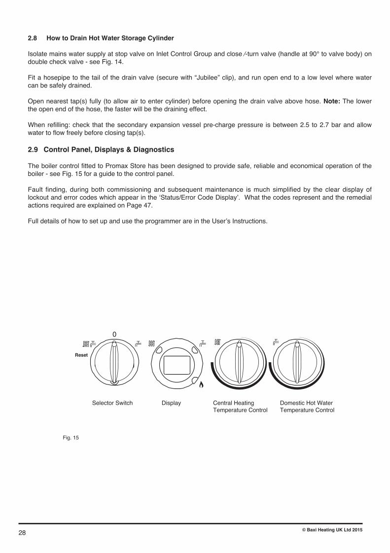
2.9 Control Panel, Displays & Diagnostics
The boiler control fitted to Promax Store has been designed to provide safe, reliable and economical operation of theboiler - see Fig. 15 for a guide to the control panel.
Fault finding, during both commissioning and subsequent maintenance is much simplified by the clear display oflockout and error codes which appear in the �Status/Error Code Display�. What the codes represent and the remedialactions required are explained on Page 47.
Full details of how to set up and use the programmer are in the User�s Instructions.
Selector Switch Display Central HeatingTemperature Control
Domestic Hot WaterTemperature Control
28 © Baxi Heating UK Ltd 2015

3. Commissioning
ImportantWhen checking for gas soundness open
all windows and doors in the room.Extinguish all naked lights, cigarettes, pipes, etc.
ImportantThe commissioning and boiler adjustment must
only be carried out by a suitably qualifiedperson. Potterton offer this service
on a chargeable basis.
Fig. 16
Manual Vent forHeat Exchanger
Combustion TestPort
Automatic Air Vent(On Pump)
Diverter ValveIndicator Lever
Isolating Valveon by-pass link
29© Baxi Heating UK Ltd 2015

3.1 Commission the Boiler
Automatic Air Vent: This is built into the pump. Leavethe cap open during and after commissioning.
Manual Air Vent: This must be used to remove as muchair as possible before firing the burner.
Warning: Do not attempt to start this boiler unless the primary circuit has been filled with water.
Preliminary Electrical System Checks
These checks must be carried out prior to attempting to start the boiler. They are, Earth Continuity, Short Circuit, Polarity & Resistance to Earth.
Flush the System
The system must be flushed in accordance with BS7593and the flushing agent manufacturer�s instructions.Further guidance can be obtained from BS5449 Section5.
Gas Soundness
Purge and test for soundness in accordance with BS6891or I.S. 813. The inlet pressure test point of the gas valveis indicated opposite. The appliance gas cock operation isshown in Fig. 9A page 20.
Unvented Domestic Hot Water System
1. Open one or more hot water taps. 2. Turn on mains water supply and observe air free water issuing from tap(s) 3. Close tap(s) and check mains water pipework for leaks 4. Check that all factory-made plumbing connections are tight and leak free (and have not loosened in transit). 5. Manually operate both the Temperature & Pressure Relief Valve and the secondary pressure relief valve and ensure that the discharge from these valves emerges safely. Close them again with a “snap” action.
Guideline times for the initial heat-up and recovery for a nominal 50 °C temperature rise (e.g. 15 °C - 65 °C) within the store are:
Unit Heat-up Recovery* 90 Litre 18 min. 15 min. 115 Litre 22 min. 18 min. 150 Litre 30 min. 23 min.
* From previous draw-off of 70% of volume.
Sealed Primary System
1. Ensure that gas supply is turned OFF at the gascock.
2. Leave the boiler switched OFF at the selector switchbut turn both the CH and DHW control knobs clockwise.
3. Move the indicator lever on the diverter valve head tothe mid position and push in so that it “latches”.
4. Check that the isolating valve on the by-pass link isOPEN (slot in-line with body).
5. Attach a length of hose to the outlet of the manualvent (1/4” manometer tube is suitable). Open the ventusing a radiator key.
6. Open the automatic air vent cap (above the pump) byone turn. Check that filling loop is connected andsupplied with water.
7. Open both valves on the filling loop and fill systemwith water. Allow water to flow from the manual ventuntil air is no longer discharged.
8. Turn the (LH) selector switch clockwise to the DHWposition and use the HW/ENTER button on theprogrammer to select hot water on ALL DAY or 24HRNOTE: Full details of how to set up and use theprogrammer are in the User�s Instructions.
9.The pump and diverter valve should now operateallowing more air to be expelled. (Free the pumpspindle if it appears to be sticking).
10. The boiler control will go to lockout after about aminute. Close the manual vent. Reset using the selectorknob, turn the gas ON and allow the boiler to startheating the cylinder contents.
11. After approx. 5 minutes, central heating can beselected by using the selector switch and programmer.
12. If a fault is suspected, consult the list of Error Codeson page 47.
Inlet PressurePoint
Outlet PressurePoint
30 © Baxi Heating UK Ltd 2015

31© Baxi Heating UK Ltd 2015
Commissioning the Boiler - Combustion Check
1. Reference should be made to BS:EN 12828 & 14336when commissioning the boiler.
2. At the time of commissioning, complete all relevantsections of the Benchmark Checklist at the rear of thispublications.
3. Having checked:• That the boiler has been installed in accordance with these instructions.
• The integrity of the flue system and the flue seals.• The integrity of the boiler combustion circuit and the relevant seals.
Proceed to put the boiler into operation as follows:
4. The Combustion Check procedure as shown by thechart on the next page is mandatory. The method ofsetting the boiler to operate at maximum andminimum rates to comply with the procedure isdescribed below.
5. Ensure that all external controls are calling for heat.The actual current boiler temperature is shown on thedisplay.
6. Turn both control knobs fully anticlockwise, then quicklyturn the right hand knob 1/4 clockwise twice and backfully anticlockwise.
7. The display will now alternate between �SF� and thecurrent boiler temperature and both green LEDs will flash.
8. To set to maximum rate.Turn the left hand knob fully clockwise. As the knob isturned the display will change, indicating the fan speed.
9. The display will show �00�, indicating maximum rate,then revert to �P � alternating with the current boilertemperature.
10. To set to minimum rate. Turn the left hand knob fully anti-clockwise. As the knob isturned the display will change, indicating the fan speed.When the display reads � 0� the boiler runs at minimumrate.
11. This function is maintained for 20 minutes unless themaximum CH temperature is exceeded. The function canbe disabled at any time by turning the right hand knob.

32
Set Boiler to Maximum RateAllow the combustion to stabilise. Do not insert probe toavoid �flooding� the analyser.
Perform Flue Integrity Combustion CheckInsert the analyser probe intothe air inlet test point, allowingthe reading to stabilise.
Is O2 � 20.6% andCO2 < 0.2% ?
Verify Flue IntegrityIndication that products ofcombustion &�inlet air are mixing - furtherinvestigation is required.Check all flue componentsare correctly assembled,fixed & supported. Checkthe flue & terminal areunobstructed.
Is O2 � 20.6% andCO2 < 0.2% ?
TURN�APPLIANCE�OFF�!Call 0344 871 1525 foradvice.The appliance MUST�NOTbe commissioned until all problems are identifiedand resolved.
Check CO & CombustionRatio at Maximum RateWhilst the boiler is still operating at maximum insertthe analyser probe into theflue gas test point, allowingthe reading to stabilise.
Is CO < 350ppmand CO/CO2 ratio< 0.004 ?
Verify Integrity of SealsCheck all burner seals,internal flue seals, door &case seals. Replace anyseals that appear unsound.
Is CO < 350ppmand CO/CO2 ratio< 0.004 ?
TURN�APPLIANCE�OFF�!Call 0344 871 1525 for advice.The appliance MUST�NOT�becommissioned until all problems are identified and resolved.If commissioning cannot befully completed the appliancemust be disconnected from thegas supply in accordance withthe GSIUR.Note: Check & record the CO&�combustion ratio at bothmaximum &�minimum ratesbefore calling 0344 871 1525.
Set Boiler to Minimum RateAllow the combustion to stabilise. Do not insert probeto avoid �flooding� the analyser.
YesNo
No Yes
No
Yes
Check CO & CombustionRatio at Minimum RateWhilst the boiler is operating at minimum insertthe analyser probe into theflue gas test point, allowingthe reading to stabilise.
Yes
No
Is CO < 350ppmand CO/CO2 ratio< 0.004 ?
No
Yes
BOILER�OPERATING�SATISFACTORILY. NO
FURTHER�ACTION�REQUIRED
Ensure test points are capped,the boiler case front panel iscorrectly fitted & secured andall other commissioningprocedures completed.Complete the �Benchmark�Checklist, recording the CO &combustion ratio readings asrequired.
Checking Combustion
1. Follow the flow chart opposite.
© Baxi Heating UK Ltd 2015

Check the Operational (Working) Gas Inlet Pressure
1. The gas valve is factory set and the burner pressurechanges as the fan modulates when demand on the boileralters. There are two important gas rates that relate to acorresponding burner pressure that can be checked asverification during a gas rate check.
2. If necessary the gas rate may be checked after runningthe boiler for 10 minutes with any other appliances andpilot lights turned off.
3. Ensure that the integral programmer and any externalcontrols are calling for heat, and the selector switch is inthe central heating and hot water position. The currentboiler temperature is shown on the display.
4. To check the gas rate it is necessary to set the boiler to�Calibration Mode�.
To carry out this operation5. Turn both temperature control knobs fully anticlockwise,then quickly turn the DHW temperature knob 1/4 turnclockwise twice and back fully anticlockwise.
6. The display will now alternate between �SF� and thecurrent boiler temperature and both green LEDs will flash.
8. Turn CH temperature control knob fully clockwise. As theknob is turned the display will change from �0� to �00�indicating maximum rate, then revert to �P� alternating withthe current boiler temperature.
9. With the boiler operating in the maximum rate conditioncheck that the operational (working) gas pressure at theinlet gas pressure test point is in accordance with B.S.6798 & B.S. 6891.
10. Ensure that this inlet pressure can be obtained with allother gas appliances in the property working.
Measure the Gas Rate11. With any other appliances & pilot lights turned OFF thegas rate can be measured.
12. A gas rate measurement may now be made.Approximate values are:-
Max 2.61 m3/hr Min 0.74 m3/hr
13. The �Calibration Function� is active for 20 minutesunless the maximum CH temperature is exceeded.
14. The function can be disabled at any time by turning theDHW temperature knob.
Central Heating System
1. Press programmer CH�button to select heating (indicated by red neon). 2. Check that any connected room thermostat is calling for heat. 3. Note that when HW�is selected the 3-way diverter valve does not allow circulation to the CH circuit until the storage cylinder contents have reached the selected temperature. After filling with cold water, this will normally take between 20 to 25 minutes.
4. With flow to the CH circuit, bleed every radiator and the pipework high points until all air or air/water mix has been removed.
N.B. Leave the cap on the auto air vent (above the pump) partially unscrewed so that the vent remains operational - note that the burner control goes to safetyshut-down if the system pressure drops below 0.5 bar.
IMPORTANT: Do not vent the boiler with the burnerrunning or damage to the heat exchanger may result.
5. Wait until the central heating circuit has reached its normal temperature of approx. 80 °C before balancing the radiators in the usual way to achieve a temperature drop of 10 °C. 6. Allow system to reach full temperature (all radiators at working temp.) and note “hot system” pressure. Switch boiler off, drain and flush the system. 7. Refill (using a suitable inhibitor) and remove all air and air/water mix. Check the relief valve is not “letting” by observing pipe outlet for several minutes. (“Letting” is usually due to debris on valve seat. Snapping the valve open-shut a few times will normally cure this). 8. Check that the system final pressure equals “hot system” pressure as noted in 7. above. Adjust if necessary. 9. Set the room thermostat or programmer according to the manufacturer�s instructions. 10.Disconnect filling loop flexible hose and leave in a secure place for householder.
Domestic Hot Water System
1. With the cylinder fully heated, check DHW output temperature is approximately 45 to 65 °C (as selected) using nearest tap and a flow rate of approximately 5 l/min. Record inlet and outlet temperatures in Benchmark Checklist. 2. Measure hot water flow rate at bath tap (fully open) and record in Benchmark Checklist. 3. Refit outer covers in reverse order.
3.2 Hand Over to the User
1. Explain the boiler controls 2. Give guidance if the system is to be shut down for long periods when freezing is possible 3. Advise the User that for continued efficient and safe operation of the boiler it is important that annual servicing is carried out. 4. Explain how to re-start boiler if red neon indicates lockout. 5. Hand over the User�s Instructions. 6. Carefully read and complete all sections of the Benchmark Commissioning Checklist at the rear of this publication that are relevant to the appliance and installation. These details will be required in the event of any warranty work. The publication must be handed to the user for safe keeping and each subsequent regular service visit recorded. For IE, it is necessary to complete a “Declaration of Conformity” to indicate compliance to I.S. 813. An example of this is given in I.S. 813 “Domestic Gas Installations”. This is in addition to the Benchmark Commissioning Checklist.
Min Gas Rate
Max Gas Rate
Burner
Pressure
(mb)
0.6 - 0.8
6.8 - 7.2
Gas
Rate
(m3/hr)
0.7 - 0.74
2.48 - 2.74
CO
(ppm)
2 - 30
30 - 100
CO2
(%)
8.4 - 8.8
8.7 - 9.2
33© Baxi Heating UK Ltd 2015

4. Service & Replacement of Parts
To ensure safe, efficient operation of the boiler, it isnecessary to carry out routine servicing at regularintervals. The frequency of servicing will depend uponthe particular installation conditions and the use to whichthe boiler is put.
Important: Before commencing any servicing orexchange of components, always turn off the gassupply and isolate the electricity supplies (i.e. toboiler and immersion heater).
Annual servicing is recommended. After completing anyservice work always test for gas soundness andRemember to fill in the Benchmark Checklist.
To gain access to the boiler for servicing, remove frontpanel and top cover as described in Section 4.1.
Annually
Important: Any 'O' rings, seals, gaskets or washers disturbed during service or replacement of parts must be visually inspected and replaced if worn or damaged.
1. Remove outer and inner top covers to gain access to heat exchanger etc. Inspect components within compartment, checking that joints are dry etc.
2. Remove the heat exchanger door complete with burner, see Section 4.14. Inspect the burner, combustion chamber and heat exchanger, carefully clean using a vacuum cleaner. DO NOT separate the burner from the heat exchanger door. Inspect the electrode condition and check gap which should be 4.5 - 5.5mm.
3. Withdraw the ionisation probe, clean with wire wool or similar abrasive, replace if necessary. Re-fit heat exchanger door.
4. Partially open vent on top of heat exchanger and release any trapped air. Check that the cap on the auto air vent (on top of pump) is partially unscrewed.
5. Draw hot water from a bath tap if necessary to cause burner to light. Check ignition is smooth and visually inspect flame. Continue to draw water until maximum fan speed is attained. Check combustion, see �Combustion Testing�.
6. Turn off the mains water supply at the Inlet Control Group and release system pressure by opening a hot tap. Using hexagon key provided, remove the pressure reducing cartridge from the Inlet Control Group. Clean the cartridge and strainer in running cold water. Re-fit the cartridge ensuring that the strainer is correctly located.
7. With no water pressure in the system, check and if necessary adjust the secondary expansion vessel pressure to approx. 2.5 to 2.8 bar (36 to 40 psi). NOTE: Vessel pressure can not be accurately set with water pressure in system.
8. Restore pressure to DHW system. Manually operate, in turn, the expansion relief valve (part of Inlet Control Group) and the temperature & pressure relief valve (Fig. 10). Check that the discharge route(s) is unobstructed and that water flows freely to a safe, visible location. Check that both valves close correctly.
9. Release CH system pressure via relief valve and check primary expansion vessel pre-charge pressure is between 1.0 to 1.2 bar. Adjust if required and top up system to same pressure.
10.Check for gas soundness and re-assemble in reverse order.
11.Clean condensate trap by removing lower nut (see section 2.4 Fig. 10a).
Combustion Testing
A combustion analysis test point is provided on the flue outlet (just above heat exchanger). The test point is sealed by a special screw/�O� ring assembly. For a correctly installed boiler typical values to be expected are: CO <100 ppm C02 <9.2 % at maximum input (Hot
condition after 10 minutes)
Levels significantly above these should be investigated and may indicate a defective component or faulty installation. Ensure the test point is FULLY GAS TIGHT. Do not substitute any other screw for the special Promax Part No. 5114700.
34 © Baxi Heating UK Ltd 2015

MAX0004C
Pull up and away Top Panel2
3
3
Pull forward Front Panelat the bottom and lift off
General Access
1
Unscrew Panel at the bottomand pull away
4.1 General Access
WARNING: Before attempting to remove anycomponent from the boiler first disconnect the mainselectricity supply by removing the plug from the wallsocket or by switching off the boiler at the externalisolating switch.
IMPORTANT: After removal or replacement of anygas carrying component a test for gas soundnessmust be made and functional check of the controlscarried out.
IMPORTANT: Any 'O ' rings, seals, gaskets orwashers disturbed during replacement of parts mustbe visually inspected and replaced if worn ordamaged.
Re-assemble all parts in reverse order.
1. Follow stages 1 - 3 (opposite) to remove the outer panels.
Internal Access2. Remove the screws securing the top engine box cover and lift the cover away from the boiler.
3. Remove the screws securing the air box cover and lift the cover away from the boiler.
4.2 Automatic Air Vent
Re-assemble all parts in reverse order.
1. Perform 4.1 General Access and drain down locally as described in 4.3
2. Pull away the securing clip and lift out the air vent parts as shown.
Fig. 17
35© Baxi Heating UK Ltd 2015

4.3 Expansion Vessel, Pump & Pressure Switch
Re-assemble all parts in reverse order.
1. Check that the cap on the auto air vent isopen. Turn the 3 isolating valves OFF andlocally drain the boilers� circuit by openingthe primary pressure relief valve.
2. Disconnect the flexible pipe at the unionbelow the pump.
3. Pull the expansion vessel forward and�spring� the RH side panel slightly to enablethe vessel to be removed.
4. Check the pre-charge pressure of thereplacement vessel is between 1.0 and 1.2 bar before fitting.
5. Reassemble in reverse order.
4.3a Pump - Head Only
1. Drain the primary circuit and disconnectthe electrical plug from the pump motor.
2. Remove the socket head screws securingthe pump head to the body and draw thehead away.
3. Reassemble in reverse order.
4.3b Pump - Complete
1. Drain the primary circuit and disconnectthe electrical plug from the pump motor.
2. Undo the two screws securing the body tothe pipe and manifold and draw the pumpforwards.
3. Unscrew the automatic air vent from thepump body.
4. Examine the �O� ring seals on the returnpipe and manifold, replacing if necessary.
5. Fit the air vent to the new pump body andreassemble in reverse order.
4.3c Automatic Air Vent
1. Drain the primary circuit and unscrew theautomatic air vent from the pump body.
2. Examine the �O� ring seal, replacing ifnecessary, and fit it to the new automatic airvent.
3. Reassemble in reverse order.
Expansion Vessel
Expansion VesselConnection Pipe
Spring Washer
Socket HeadedScrew
Pump Head
Pump Body
AutomaticAir Vent
Fig. 18
36 © Baxi Heating UK Ltd 2015
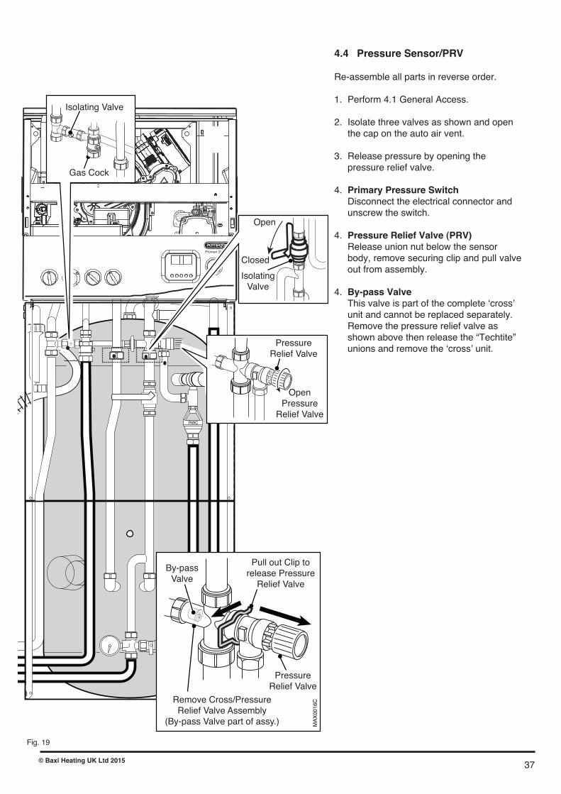
4.4 Pressure Sensor/PRV
Re-assemble all parts in reverse order.
1. Perform 4.1 General Access.
2. Isolate three valves as shown and open the cap on the auto air vent.
3. Release pressure by opening the pressure relief valve.
4. Primary Pressure Switch Disconnect the electrical connector and unscrew the switch.
4. Pressure Relief Valve (PRV) Release union nut below the sensor body, remove securing clip and pull valve out from assembly.
4. By-pass Valve This valve is part of the complete �cross� unit and cannot be replaced separately. Remove the pressure relief valve as shown above then release the “Techtite” unions and remove the �cross� unit.
RWC
MAX0002D
Promax Store
Pull out Clip torelease PressureRelief Valve
PressureRelief Valve
Remove Cross/PressureRelief Valve Assembly
(By-pass Valve part of assy.)
By-passValve
MAX0016C
IsolatingValve
Closed
Open
OpenPressureRelief Valve
PressureRelief Valve
Gas Cock
Isolating Valve
Fig. 19
37© Baxi Heating UK Ltd 2015

4.5 Gas Valve
1. Turn the gas cock OFF and disconnectthe electrical plug.
2. Pull off the earth lead and sensing pipe.
3. Undo the nuts on the venturi inlet pipeand valve inlet pipe. Remove the gas valve.
4. Examine the sealing washers, replace ifnecessary.
5. Reassemble in reverse order, ensuringthe sealing washers are in place.
IMPORTANT: The CO2 must be checkedand adjusted (see Commissioning Checkson p.31 and 32).
4.6 Fan
1. Remove the air box front cover.
2. Undo the nut on the gas inlet pipe to theventuri and pull the sensing pipe off the fan.Examine the sealing washer and replace ifnecessary.
3. Undo the screws securing the manifold tothe extension piece.
4. Partially remove the manifold and fanassembly, being careful to retain the injectorin the venturi. Disconnect the fan electricalplugs before completely removing theassembly.
5. Undo the screws securing the fan to theventuri and fit the new fan, replacing the sealif necessary.
6. Examine the gasket behind the manifoldand replace if necessary.
7. Reassemble in reverse order, ensuringthat the injector is in place and the sensingpipe is connected to the fan.
Fig. 20
Gas Valve
ValveInlet Pipe
Gas FeedElbow
Earth Lead
SensingPipe
Venturi InletPipe
Cover
Fan
Venturi
Manifold
BurnerGasket
Sensing Pipe
Injector
Sealing Washer
Sealing Washer
38 © Baxi Heating UK Ltd 2015

Fig. 21
4.7 Igniter
1. Remove the air box front cover.
2. Disconnect the igniter feed plug and theelectrode leads, noting their positions.
3. Undo the screw securing the bracket to theboiler.
4. Remove the igniter and transfer thebracket to the new component.
5. Reassemble in reverse order.
4.8 Spark and Sensing Electrodes
1. Disconnect the electrode leads, notingtheir positions.
2. Remove the retaining screws securingeach of the electrodes to the combustion boxcover and remove the electrodes.
3. Check the condition of the sealing gasketsand replace if necessary. Reassemble inreverse order.
4.9 Overheat Thermostat
Re-assemble all parts in reverse order.
1. Perform 4.1 General Access.
2. Disconnect electrical connections and unscrew the thermostat. Polarity of the wires is not important.
Igniter
Igniter FeedPlug
ElectrodeLeads
Bracket
SparkElectrode
SensingElectrode
ElectrodeLeads
39© Baxi Heating UK Ltd 2015

Fig. 22
4.10 Burner
1. Remove the fan/manifold assembly - seeSection 4.6.
2. Undo the screws securing the spacer tothe cover.
3. Withdraw the burner from the cover andreplace with the new one.
4. Replace the burner gasket.
5. Reassemble in reverse order.
4.11 Insulation
1. Remove the electrode leads, noting theirpositions. Also remove the electrodes.
2. Undo the screws securing the cover to theheat exchanger. Draw the cover assemblyaway.
3. Remove the cover insulation piece.
4. Fit the new insulation carefully over theburner and align it with the slots for theelectrodes.
5. The rear insulation is retained by a screwand large washer, remove these and drawthe insulation out of the heat exchanger.
6. Examine the cover seal and replace ifnecessary.
HeatExchanger
RearInsulation
CoverInsulation
Seal
Manifold
SparkElectrode
SensingElectrodeElectrode
Leads
Venturi
Cover
Burner
Gasket
Extension Piece
Manifold
Venturi
40 © Baxi Heating UK Ltd 2015
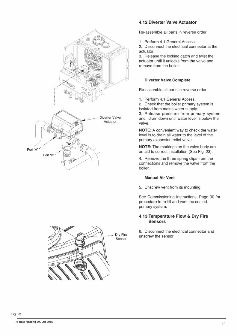
4.12 Diverter Valve Actuator
Re-assemble all parts in reverse order.
1. Perform 4.1 General Access.2. Disconnect the electrical connector at the actuator.3. Release the locking catch and twist the actuator until it unlocks from the valve and remove from the boiler.
Diverter Valve Complete
Re-assemble all parts in reverse order.
1. Perform 4.1 General Access.2. Check that the boiler primary system is isolated from mains water supply.3. Release pressure from primary systemand drain down until water level is below the valve.
NOTE: A convenient way to check the water level is to drain all water to the level of the primary expansion relief valve.
NOTE: The markings on the valve body are an aid to correct installation (See Fig. 23).
4. Remove the three spring clips from the connections and remove the valve from the boiler.
Manual Air Vent
5. Unscrew vent from its mounting.
See Commissioning Instructions, Page 30 forprocedure to re-fill and vent the sealed primary system.
4.13 Temperature Flow &�Dry Fire Sensors
6. Disconnect the electrical connector and unscrew the sensor.
Fig. 23
Diverter ValveActuator
Dry FireSensor
Port �A�
Port �B�
41© Baxi Heating UK Ltd 2015
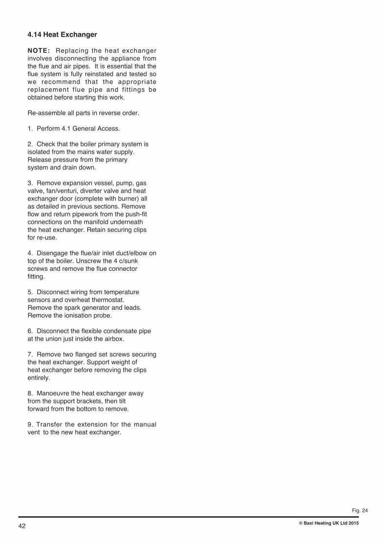
4.14 Heat Exchanger
NOTE: Replacing the heat exchangerinvolves disconnecting the appliance fromthe flue and air pipes. It is essential that theflue system is fully reinstated and tested sowe recommend that the appropriatereplacement f lue pipe and fitt ings beobtained before starting this work.
Re-assemble all parts in reverse order.
1. Perform 4.1 General Access.
2. Check that the boiler primary system is isolated from the mains water supply. Release pressure from the primary system and drain down.
3. Remove expansion vessel, pump, gas valve, fan/venturi, diverter valve and heat exchanger door (complete with burner) all as detailed in previous sections. Remove flow and return pipework from the push-fit connections on the manifold underneath the heat exchanger. Retain securing clips for re-use.
4. Disengage the flue/air inlet duct/elbow ontop of the boiler. Unscrew the 4 c/sunk screws and remove the flue connector fitting.
5. Disconnect wiring from temperature sensors and overheat thermostat. Remove the spark generator and leads.Remove the ionisation probe.
6. Disconnect the flexible condensate pipe at the union just inside the airbox.
7. Remove two flanged set screws securingthe heat exchanger. Support weight of heat exchanger before removing the clips entirely.
8. Manoeuvre the heat exchanger away from the support brackets, then tilt forward from the bottom to remove.
9. Transfer the extension for the manualvent to the new heat exchanger.
Fig. 24
42 © Baxi Heating UK Ltd 2015

4.15 Replacement of Immersion Heater and Immersion Heater Combined Thermostat/Thermal Cut-out
The cylinder must be fully drained prior to removing the immersion heater. Refer to Section 2.8 for the procedure to drain theunit.
1. Important: Ensure ALL power supplies are isolated before starting work on the boiler. Perform the actions detailed in section 4.1 General Access. Note: only the two lower front panels need be removed for this servicing action, follow instructions 3 and 4 for how to remove these panels.
2. Remove the immersion heater cover by removing the securing nut and pulling the cap away from the cylinder.
3. Disconnect the electrical supply cable from the thermostat and the earth post assembly. Remove the thermostat from the immersion heater by carefully pulling outwards. DO NOT twist the thermostat as damage to the connections to the immersion heater may occur.
4. To remove the immersion heater unscrew the brass backnut using the key spanner supplied with the unit. Retain the backnut. Over time the immersion heater gasket may become stuck to the mating surface. To break the seal insert a round bladed screwdriver into one of the pockets on the immersion heater and gently lever up an down.
5. Withdraw the immersion heater from the cylinder. Note: the immersion heater is curved downwards 90 degrees to reach the base of the cylinder. When removing, the head of the immersion heater should be tilted towards the floor for ease of withdrawal.
6. Insert the immersion heater into the boss ensuring the right angled element hangs vertically downwards towards the base of the unit. Push the immersion heater mounting plate into the boss so the gasket seats on the flange at the base of the boss. It may be helpful to support the immersion heater using a round bladed screwdriver inserted into one of the pockets on the immersion heater whilst the brass backnut is tightened. Tighten the brass backnut using the key spanner supplied.
7. Fit the thermostat by sliding the stem into the upper pocket and carefully plugging the two male spade terminals on the underside of the thermostat head into the corresponding female terminations on the element. Carefully push home until the terminals are fully engaged.
8. Re-connect the electrical supply to the thermostat and earth post. The Live (Brown) conductor should be connected directly to the thermostat terminal marked A. The Neutral (Blue) conductor should be connected directly to the thermostat terminal marked B. The earth conductor should be connected to the threaded post on the bracket marked .
9. Re-fit the protective cover over the immersion heater assembly and secure using the nut previously removed.
10. Ensure the cylinder is correctly re-filled prior to switching on the immersion heater. Do not operate the immersion heater with the protective cover removed.
SPOT WELDED TO IMERSION HEATER BOSS
EARTH BRACKETM5 NUTEARTHLABEL
EARTHWARNINGLABEL
CUPWASHER
PLAINWASHER
SHAKEPROOFWASHER
M5 THREADEDPILLAR
Fig. 25
43© Baxi Heating UK Ltd 2015

4.16 Gas/Air Valve Setup Procedure
Checking the CO2
1. The combustion (CO2) may be checked at maximumrate using a suitably calibrated analyser after runningthe boiler for several minutes.
2. To do this it is necessary to set the boiler to�Calibration Mode�.
3. Ensure that all external controls are calling for heat.The actual current boiler temperature is shown on thedisplay.
4. Turn both temperature control knobs fullyanticlockwise, then quickly turn the DHW temperatureknob 1/4 clockwise twice and back fully anticlockwise.
5. The display will now alternate between �SF� and thecurrent boiler temperature and both green LEDs willflash.
6. Turn the CH temperature knob fully clockwise. Asthe knob is turned the display will change, indicatingthe percentage of maximum fan speed.
7. The display will show �00�, indicating maximum rate,then revert to �P � alternating with the current boilertemperature.
8. Remove the plug from the flue adaptor test point.Insert the analyser probe and allow time for thereading to settle.
The CO2 should be 8.9% ± 0.2
9. It is possible to alter the CO2 by adjustment of thegas valve. At maximum rate the �Max. Rate� throttleadjustment screw should be turned clockwise todecrease CO2, anti-clockwise to increase CO2 using asuitable 2.5mm hexagon key, until the correct readingis obtained.
10. The CO2 must then be checked at minimum rate.Turn the CH temperature knob fully anticlockwise. Asthe knob is turned the display will change, indicatingthe fan speed. When the display reads � 0� the boilerruns at minimum rate.
The CO2 should be 8.6% ± 0.2.
11. If at minimum CO2 is not correct please ring ourafter sales service department.
12. The �Calibration Function� is maintained for 20minutes unless the maximum CH temperature isexceeded. The function can be disabled at any time byturning the DHW knob.
MAX0031B
Air/GasRatio Valve
Top View
Inlet PressureTest Point
Outlet PressureTest Point
Signal sensing tube connected to Fan
Air SignalConnection
OffsetAdjustment
ThrottleAdjustment
Flue AdaptorTest Point
Min Gas Rate
Max Gas Rate
Burner
Pressure
(mb)
0.6 - 0.8
6.8 - 7.2
Gas
Rate
(m3/hr)
0.7 - 0.74
2.48 - 2.74
CO
(ppm)
2 - 30
30 - 100
CO2
(%)
8.4 - 8.8
8.7 - 9.2
44 © Baxi Heating UK Ltd 2015
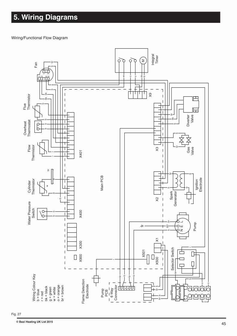
5. Wiring Diagrams
Fig. 27
Pu
mp
Sele
cto
r S
witch
Sp
ark
Ge
nera
tor
Ga
s
Va
lve
Div
ert
er
Va
lve
Inte
gra
l
Tim
er
Fa
n
Main
PC
BP
um
p
PC
B
Fla
me
Dete
ction
Ele
ctr
ode
Cylin
der
The
rmis
tor
Flo
w
The
rmis
tor
Wa
ter
Pre
ssu
re
Sw
itch
Flu
e
Th
erm
isto
rO
ve
rhe
at
The
r mo
sta
t
X900 X501
X300
X4
00
X4
01
X500
X1
X2
X3
X9
M
1
1 3
2 4 5
Ign
itio
n
Ele
ctr
od
e
br
bb
bb
bb
bb
gg
b
rr
g
bk
bk
o ow bbr
b
g
w
br
bb
r
br
bb
bk
br
NE
L
o
o o
br
br
bb
rb
br
bbr bbr
r
Wirin
g C
olo
ur
Ke
y
b =
blu
e
r =
red
bk =
bla
ck
g =
gre
en
w =
wh
ite
o =
ora
nge
br
= b
row
n
6 W
ay
Conne
cto
r
g/y
Wiring/Functional Flow Diagram
45© Baxi Heating UK Ltd 2015
brw

Fig. 28
- brown- black- blue- white
brbkbw
- green- green / yellow- red- orange
gg/yro
Control PCB
X2 X3
X9
X501
1 21 2 33 44 55 6 7 8 9
X1
1 2
CylinderThermistor
Reset Selector Switch
FlowThermistor
Fan
Gas Valve
Overheat Stat
FlameSensingElectrode
Pump
Mains Input Linkg/y
b
br
Flue Thermistor
X400 X401
br
w
bb
rr
b
b
bb
b
br
bk
g
b
br
g/y
b br
br
b
bbr
b
br
r o
r
o
o
br
b
b
br
Water PressureSwitch
SparkGenerator
IgnitionElectrode
9 8 7 5 4 2 1 910 8 7 6 5 4 3 2 1
br
bk
b
b
bk
br
Diverter Valve
12
34
NL
w
g
1
42
5
3
1
2
ab
r
br
o
o
b
bw
Timer6 3
gg
g/y
X1
X2 X3
b
br
b
br
b br
PumpPCB
6 Way Connector
bbr
46 © Baxi Heating UK Ltd 2015

6. Fault Finding Guide
Boiler Fault Finding
NOTE: When instructed to turn theselector to the reset position turn theselector switch fully anticlockwiseagainst the spring pressure to the resetposition and hold for 5 seconds to resetthe boiler.
Initial Fault Finding Checks
1. Check that gas, water and electrical suppliesare available at the boiler.
2. Electrical supply = 230V ~ 50 Hz.
3. CH water system pressurised to 0.5 barminimum when the boiler is cold.
4. The preferred minimum gas pressure is 20mbar.
5. Carry out electrical system checks, i.e. EarthContinuity, Resistance to Earth, Short Circuit andPolarity with a suitable meter.
NOTE: These checks must be repeated afterany servicing or fault finding.
6. Ensure all external controls are calling for heatand check all external and internal fuses. Beforeany servicing or replacement of parts, ensure thegas and electrical supplies are isolated.
Error Codes
1. If a fault occurs on the boiler an error code maybe shown by the facia display.
2. The codes are either two or three digit,preceded by the letter 'E'. For example, codeE133 will be displayed by 'E1' alternating with '33'.E50 is shown as 'E' then '50'
E20, E28 & E50 indicate faulty components orwiring harness.
E110 shows overheat of the primary water andE130 overheat of the flue system.
E119 is displayed when the primary waterpressure is less than 0.5 bar.
E133 indicates that the gas supply has beeninterrupted, ignition has failed or the flame hasnot been detected.
E125 is displayed in either of two situations:-i) If within 15 seconds of the burner lighting theboiler temperature has not changed by 1°.ii) If within 10 minutes of the burner lighting theboiler temperature twice exceeds the selectedtemperature by 30°.In these instances the pump is probablyinoperative.
3. By turning the selector switch to the 'Reset'position for a minimum of 5 seconds when E110,E130 & E133 are displayed it is possible to relightthe boiler.
4. If this does not have any effect, or the codesare displayed regularly further investigation isrequired.
Central Heating NTC FaultFlue NTC FaultHot Water NTC Fault Safety Thermostat OperatedWater Pressure Switch Not OperatedPump Fault or Primary Circulation ProblemTank Thermistor not in TankFlue NTC OperatedInterruption Of Power Supply while in fault modeInterruption Of Gas Supply or Flame FailureFan or Fan Wiring FaultPre-Circulation Fault
E20E50E28E110E119E125
E130E131E133E160E193
Table Of Error Codes
47© Baxi Heating UK Ltd 2015

Refer to Section “Illustrated Wiring Diagram” for position of terminals and componentsCentral Heating - Follow operational sequence
Turn selector switch to The display illuminates
Error 20, 28 or 50 flashing
Error 119 flashing
Burner lights
Error 110 flashingError 130 flashingError 133 flashing
Turn Central Heatingthermostat to Maximum.
Pump runs
Fan runs
Spark at ignition electrodesfor up to 5 seconds and for
3 attempts
3-way valve is open toCentral Heating circuit
Go to section �A�
Go to section �E�
Ensure all controls andintegral clock are calling
for heat
Go to section �J�
Go to section �B�
Error 160 flashingGo to section �D�
Error 133 flashing
Burner does not stayalights after 5 seconds
Error 133 flashingGo to section �H�
Operation sequencesuccessful
If the error 110 is stillflashing. Go to section �I�
Fan runs at correct speed
YES
YES
NO
NO
NO
YES
YES
YES
YES
YES
YES YES
YES
NO
YES YES
YES
YES
NO
NO
NO
NO
NO
Burner output modulates tomaintain the temperature
set
Burner goes out
Go to section �C�
Ensure controls are set todemand and verify the
contacts are closed
Error 160 flashingGo to section �K�
YESGo to section �G�
Turn the selector switch toreset
Go to section �F�
Error 130 flashingGo to section �L�
YES
Check the Central HeatingNTC sensor
Go to section �E�
Fan stops after 10seconds
Pump continues to run for3 minutes
(room thermostat open)
NO
NO
YES
NO
YES YES
Turn the selector switch toreset position for 5 seconds
Error 125 or 193 flashingEnsure that primary
circulation is OK & thatthere is no blockage
YES
NO
48 © Baxi Heating UK Ltd 2015

Turn selector switch to The display illuminates
Error 20, 28 or 50 flashing
Error 119 flashing
Burner lights
Error 110 flashingError 133 flashing
Fan runs
Spark at ignition electrodesfor up to 5 seconds and for
3 attempts
3-way valve is open toDomestic Hot Water circuit
Go to section �A�
Go to section �E�
Go to section �J�
Error 160 flashingGo to section �D�
Error 133 flashing
Burner does not stayalights after 5 seconds
Error 133 flashingGo to section �H�
Operation sequencesuccessful
Turn the selector switch toreset position for 5 seconds
If the error 110 is stillflashing. Go to section �I�
Fan runs at correct speed
YES
NO
NO
NO
YES
YES
YES
YES
YES YES
NO
YES YES
YES
YES
NO
NO
NO
NO
Go to section �C�
Error 160 flashingGo to section �K�
YESGo to section �G�
Turn the selector switch to thereset position for 5 seconds
Go to section �F�NO
YES
Domestic Hot Water - Follow operational sequence
Pump runs
YES
Error 125 flashingGo to section �B�
NO
Select HW �On All Day� or24Hr at programmer
NO
49© Baxi Heating UK Ltd 2015

Fault Finding Solutions Sections
Is there 230V at:
Main terminals L and N Check electrical supply1. NO
Main terminal fuse Replace fuseReplace PCB
Displayilluminated
2. NO
PCB - X1 connectorterminals 1,2
Check wiring3. NO
NO
A
CH system pressure less than 0.5 bar Re-pressurise system1. YES
Check the tap of the automaticair vent is opened
Open the automatic air vent2. NO
C
1.
NO
YESFan connections correct at fan.PCB - X2 connector, is 230V ACacross terminals 5 & 7
Fan jammed or faulty winding
Replace PCB
Replace fanYESD
NO
Replace waterpressure switch
Check connection waterpressure switch terminalCOM - NO and PCB connectorX400 terminals 3,4
YES
50 © Baxi Heating UK Ltd 2015
Is there 230V at:
X3 Connection Pump PCB1. NO
YES
BCheck incoming wiring
X2 Connection Pump PCBNO
Replace Pump PCB
YES
X1 Control PCBNO
Check wiring
YES
X3 Control PCB, T3, T4NO
Replace Control PCB
YES
X1 Pump PCBNO
Replace Pump PCB
YES
Replace Pump

Temperature sensors faulty.Cold resistance approximately10k� @ 25° C (DHW and CH sensors)20k� @ 25° C (Flue sensor)(resistance reduces with increase in temp.)
NO
EReplace sensor
Gas at burner Ensure gas is on and purged
Replace PCB
Replace gas valvePCB - X3 connector is 230V AC
across terminals 1 & 2YES
NO
NO
F
Replace PCBCheck and correct if necessary1. Ignition electrode and lead2. Electrode connection3. Spark gap and position
Voltage at PCB - X2 connector is110V DC across terminals 2 & 5(Note: from multimeter connect�common� to 2 & �volts� to 5)Check wiring
YESNO
Replace igniterYES
G
Check and correct the connection ofthe tube between the venturi and
gas valve
1.
2.
5.5
8.5
13
Electrode Position
Viewing Window
Burner
51© Baxi Heating UK Ltd 2015

Check and correct if necessary1. The mechanical set of the gas valve(CO2 values - see instruction)2. Flame sensing electrode and lead connections3. Flame sensing electrode position
Flame current should be more than 0.5 �AReplace PCB
Replace PCB
YES
YES
Replace flame sensing electrodeNO
Check the gas supply pressure:For Natural Gas greater than
10 - 11 mbar
H
J
Replace safety thermostatYESNOOverheat thermostat operated
or faulty, i.e. continuity acrossthermostat terminals
Allow to cool. Continuityacross thermostat terminals
more than 1.5 ohm
I
K
L
Is there 230V at:
Motor 3-way valve Replace diverter valve actuator1. YES
PCB - X3 connector terminals 5 & 6 central heating mode 5 & 7 domestic hot water mode
Replace PCB2. NO
Change pump supply cable
YES
Fan connections correct at fan.PCB - X401 connector terminals 5,6,7 & 8
1. YESReplace fan
Temperature sensors faulty.Cold resistance approximately10k� @ 25° C (CH sensor)20k� @ 25° C (Flue sensor)(resistance reduces with increase in temp.)
NOReplace sensor
YESIf pump is running the heat exchanger couldbe obstructed
Replace heat exchanger
1.
2.
1.
2.
1.
52 © Baxi Heating UK Ltd 2015

Fig. 29
7. Short List Of Spare Parts
Short Parts List
Key G.C. Description ManufacturersNo. No. Part No.
490 Fan 5129230
441 Igniter Electrode 5114702
442 Sensing Electrode 5117275
480 Gas Valve 720301001
410 Burner 5114697
535 Water Pressure Switch 5114748
520 Pump 7220533
402 Flue Thermostat 5114747
531 NTC Sensor 5114725
530 Overheat Thermostat 5106291
235 Pressure Gauge 248090
205 PCB 5117086
220 Selector Switch 248095
215 Battery (Programmer) 5118231
231 Knob 5116069
A Pump PCB 7222704
410
441 442
490
480
535
520
402
531
530
205235
215
231
220
53© Baxi Heating UK Ltd 2015
A

*All installations in England and Wales must be to Local Authority Building Control (LABC) either directly or through a
Competent Persons Scheme. A Building Regulations Compliance will then be issued to the customer.
www.centralheating.co.uk© Heating and Hotwater Industry Council (HHIC)
This Commissioning Checklist is to be completed in full by the competent person who commissioned the boiler as a means of demonstrating
compliance with the appropriate Building Regulations and then handed to the customer to keep for future reference.
Failure to install and commission according to the manufacturer’s instructions and complete this Benchmark Commissioning Checklist will invalidate the
warranty. This does not affect the customer’s statutory rights.
GAS BOILER SYSTEM COMMISSIONING CHECKLIST
Customer name: Telephone number:
Address:
Boiler make and model:
Boiler serial number:
Commissioned by (PRINT NAME): Gas Safe register number:
Company name: Telephone number:
Company address:
Commissioning date:
CONTROLS (tick the appropriate boxes)
Time and temperature control to heatingRoom thermostat and programmer/timer Programmable room thermostat
Load/weather compensation Optimum start control
Time and temperature control to hot water Cylinder thermostat and programmer/timer Combination Boiler
Heating zone valves Fitted Not required
Hot water zone valves Fitted Not required
Thermostatic radiator valves Fitted Not required
Automatic bypass to system Fitted Not required
Boiler interlock Provided
ALL SYSTEMS
’s instructions Yes
What system cleaner was used?
What inhibitor was used? Quantity litres
Yes No
CENTRAL HEATING MODE measure and record:
Gas rate m³/hr OR ft³/hr
Burner operating pressure (if applicable) mbar OR Gas inlet pressure mbar
°C
Central heating return temperature °C
COMBINATION BOILERS ONLY
Is the installation in a hard water area (above 200ppm)? Yes No
Yes No
DOMESTIC HOT WATER MODE Measure and Record:
Gas rate m³/hr OR ft³/hr
Burner operating pressure (at maximum rate) mbar OR Gas inlet pressure at maximum rate mbar
Cold water inlet temperature °C
Hot water has been checked at all outlets Yes Temperature °C
I/min
CONDENSING BOILERS ONLY
The condensate drain has been installed in accordance with the manufacturer’s instructions and/or BS5546/BS6798 Yes
ALL INSTALLATIONS
Record the following:At max. rate: CO ppm AND CO/CO² Ratio
At min. rate: (where possible) CO ppm AND CO/CO² Ratio
The heating and hot water system complies with the appropriate Building Regulations Yes
The boiler and associated products have been installed and commissioned in accordance with the manufacturer’s instructions Yes
The operation of the boiler and system controls have been demonstrated to and understood by the customer Yes
The manufacturer’s literature, including Benchmark Checklist and Service Record, has been explained and left with the customer Yes
Commissioning Engineer’s Signature
Customer’s Signature
www.centralheating.co.uk
54

www.centralheating.co.uk
It is recommended that your heating system is serviced regularly and that the appropriate Service Interval Record is completed.
Service Provider
Before completing the appropriate Service Record below, please ensure you have carried out the service as described in the manufacturer’s instructions.
SERVICE RECORD
SERVICE 01 Date:
Engineer name:
Company name:
Telephone No:
Gas safe register No:
Record:At max. rate: CO ppm AND CO² %
At min. rate: (Where Possible) CO ppm AND CO² %
Comments:
Signature
SERVICE 02 Date:
Engineer name:
Company name:
Telephone No:
Gas safe register No:
Record:At max. rate: CO ppm AND CO² %
At min. rate: (Where Possible) CO ppm AND CO² %
Comments:
Signature
SERVICE 03 Date:
Engineer name:
Company name:
Telephone No:
Gas safe register No:
Record:At max. rate: CO ppm AND CO² %
At min. rate: (Where Possible) CO ppm AND CO² %
Comments:
Signature
SERVICE 04 Date:
Engineer name:
Company name:
Telephone No:
Gas safe register No:
Record:At max. rate: CO ppm AND CO² %
At min. rate: (Where Possible) CO ppm AND CO² %
Comments:
Signature
SERVICE 05 Date:
Engineer name:
Company name:
Telephone No:
Gas safe register No:
Record:At max. rate: CO ppm AND CO² %
At min. rate: (Where Possible) CO ppm AND CO² %
Comments:
Signature
SERVICE 06 Date:
Engineer name:
Company name:
Telephone No:
Gas safe register No:
Record:At max. rate: CO ppm AND CO² %
At min. rate: (Where Possible) CO ppm AND CO² %
Comments:
Signature
SERVICE 07 Date:
Engineer name:
Company name:
Telephone No:
Gas safe register No:
Record:At max. rate: CO ppm AND CO² %
At min. rate: (Where Possible) CO ppm AND CO² %
Comments:
Signature
SERVICE 08 Date:
Engineer name:
Company name:
Telephone No:
Gas safe register No:
Record:At max. rate: CO ppm AND CO² %
At min. rate: (Where Possible) CO ppm AND CO² %
Comments:
Signature
SERVICE 09 Date:
Engineer name:
Company name:
Telephone No:
Gas safe register No:
Record:At max. rate: CO ppm AND CO² %
At min. rate: (Where Possible) CO ppm AND CO² %
Comments:
Signature
SERVICE 10 Date:
Engineer name:
Company name:
Telephone No:
Gas safe register No:
Record:At max. rate: CO ppm AND CO² %
At min. rate: (Where Possible) CO ppm AND CO² %
Comments:
Signature
*All installations in England and Wales must be to Local Authority Building Control (LABC) either directly or through a
Competent Persons Scheme. A Building Regulations Compliance will then be issued to the customer.
© Heating and Hotwater Industry Council (HHIC) 55

7221756 - 01 (04/15)
0086
Baxi Customer Support0344 871 1525
Opening hoursMonday - Friday, 8.00am-6.00pm
Weekends and Bank Holidays, 8.30am-2.00pm
Please note calls may be recorded for training and monitoring purposes
baxi.co.uk
Register now to activate your warranty:
www.baxi.co.uk/registration
For the warranty to be maintained, please make sure...
Benchmark checklist is completedWarranty is registered with BaxiThe boiler has an annual service
1
2
3
For full terms and conditions, visit www.baxi.co.uk/terms. Failure to adhere toterms and conditions will void your manufacturer’s warranty.
BaxiBrooks House,Coventry Road,Warwick, CV34 4LL
Please ensure the boiler is installed in accordance with these installationinstructions and that you adhere to the Building Regulations.
e&oeAll descriptions and illustrations provided in this document have beencarefully prepared but we reserve the right to make changes andimprovements in our products which may affect the accuracy of theinformation contained in this leaflet. All goods are sold subject to ourstandard Conditions of Sale which are available on request. part of