(i~ and 2~ litre)
TRANSCRIPT
SECTION CTHE IGNITION EQUIPMENT
(I~ and 2~ LITRE)
General Description.
Section No. C.l
Section No. C.2
Section No. C.3
Section No. C.4
Section No. C.5Section No. C.6
Section No. C.7
Section No. C.8
Section No. C.9
Section No. C.10
Section No. C. II
Section No. C.12
Section No. C.13
Section No. C.14
Testing with the sparking plugs in position tolocate the cause of uneven firing.
Testing the low-tension circuit.
The high-tension cables.
Attention to the sparking plugs.
The contact breaker mechanism.
Distributor lubrication.
Removal and replacement of the distributor.
Ignition timing.Dismantling the distributor.
The condenser.
Fitting new distributor bushes.
Reassembling the distributor.
Distributors with ‘‘ high-lift cams.
Vacuum controlled distributors (2~ litre).
GENERAL DESCRIPTION
The ignition is by coil and distributor, which is pro-vided with centrifugal automatic advance mechanism.There is also a manual control which gives an advancerange of approximately 15 degrees.The positive earth system is used.NOTE.—Later cars are fitted with modified
distributors having “high-lift” cams. Thesedistributors require a different contact breakersetting from the earlier types, and it is thereforeimperative to consult Section C.13 to ascertainthe correct contact breaker gap before carryingout any operation which involves re-setting thecontact breaker.
LITRE
DistributorThis is a Lucas Model DKY.4A. On earlier engines
the Riley Service No. is S.502 and the Lucas ServiceNo. is 405546. The identification marks are stampedon the side of the unit.
Series RMF engines have a distributor which bearsthe Riley Service No. 166182, and the Lucas ServiceNo. *10277. Commencing at Engine No. RMB.2/1288, adistributor incorporating suction operation was fitted.The Riley Service No. is 166250 and the Lucas ServiceNo. 40336A.
Ignition coilThis is a Lucas Model B.12, Service No. 45012A.
The identification marks are stamped on the base ofthe coil.
Sparking plugsThese are Champion NA.8, 14 mm., with a gap of
.025 in. (.63 mm.).
LITREDistributor
This is a Lucas Model DKY.4A, Riley Service No.D.7281, and the Lucas Service No. 404425. AfterEngine No. 7224 a different distributor is fitted whichbears the Riley Service Part No. 300158, and the LucasService No. 40182, and on these distributors theidentification marks are stamped on the side of theunit.
Ignition coilThis is a Lucas Model B.12, Service No. 45012A.
The identification marks are stamped on the base ofthe coil.
Sparking plugsThese are Champion L.IOS, 14 mm., with a gap of
•025 in. (.63 mm.).
I
Riley I~ and 2~ Litre. Issue 3 (H & E) 87302—5/54 C. I

(1+ and 2+ LITRE)C THE IGNITION EQUIPMENT
Section C.l
TESTING WITH SPARKING PLUGSIN POSITION TO LOCATE THE
CAUSE OF UNEVEN FIRINGTest in position to locate cause of uneven firing
(a) Start the engine and set it to run at a fairlyfast idling speed.
(b) Short-circuit each plug in turn by placing ahammer head or the blade of a wooden-handledor insulated-type screwdriver between theterminal and the cylinder head. No differencein the engine performance will be noted whenshort-circuiting the plug in the defectivecylinder. Shorting the other plugs will makeuneven running more pronounced.
(c) Having located the cylinder which is at fault,stop the engine and remove the cable fromthe terminal of the sparking plug. Restartthe engine and hold the end of the cable .about~ in. from the cylinder head.
(d) If the sparking is strong and regular, the faultprobably lies in the sparking plug. Removethe plug, clean, and adjust the gap to the correctsetting or alternatively fit a replacement plug.
(e) If there is no spark or if it is weak and irregular,examine the cable from the sparking plug tothe distributor. After a long period of servicethe rubber insulation may be cracked orperished, in which case the cable should berenewed. Finally, examine the distributormoulded cap, wipe the inside and outside witha clean dry cloth, see that the carbon brushmoves freely in its holder and examine themoulding closely for signs of breakdown.After long service it may have become tracked,that is, a conducting path may have formedbetween two or more of the electrodes orbetween one of the electrodes and some partof the distributor in contact with the cap.Evidence of a tracked cap is shown by thepresence of a thin black line in the placesindicated. A replacement distributor cap mustbefitted in placeofonethat hasbecometracked.
Section C.2
TESTING THE LOW-TENSION CIRCUITTesting in position. Low-tension circuit
(a) Spring back the securing clips on the distributorand remove the moulded cap and rotor. Ifthe rotor is a tight fit, it can be levered offcarefully with a screwdriver.
(b) Check that the contacts are clean and freefrom pits, burns, oil or grease. Turn theengine and check that the contacts are openingand closing correctly and that the clearancewhen the contacts are fully opened is between•010 in. and .012 in. (.25 mm. and •30 mm.).
Correct the gap if necessary. (See Section C.5.)(c) Switch on the ignition, turn the engine with
the starting handle and observe the ammeterreading, which should rise and fall with theclosing and opening of the contacts. If thereading fluctuates in this way, the low-tensioncircuit is in order.
(d) If the ammeter reading remains steady, locatethe fault in the low-tension circuit.
(e) Another method of testing is to disconnectthe cable at the contact breaker terminal ofthe coil and at the low-tension terminal of thedistributor, and connect a test lamp betweenthese terminals. If the lamp lights when thecontacts close and goes out when the contactsopen, the low-tension circuit is in order.
Fig. C.l.Demonstrates the correctmethod of fitting the high-tensioncable to the mouldedterminal nut of the ignition
coil.
Low-tension circuit—to locate fault(a) Having determined, by testing as previousl1
described, that the fault lies in the low tensioncircuit, switch on the ignition, and turn theengine until the contact breaker points arefully opened.
(b) Check the circuit with a voltmeter (0—20 volts)as followsNote.—If the circuit is in order the reading onthe voltmeter should be approximately 12 volts.
(c) Battery to starter switch. Connect voltmeterto starter switch terminal and to earth. Noreading indicates faulty cable or loose con-n ectio ns.
(d) Starter switch to ammeter (brown lead). Con-nect a voltmeter to the ammeter terminal andto earth. No reading indicates faulty cable orloose connections.
TERMINAL STRANDS
C.2 Riley 1+ and 2+ Litre, Issue 3 (H & E) 87302—5/54

(1+ and 2{ LITRE) TtE1~ IGNITION EQUIPMENT C(e) Ammeter. Connect a voltmeter to the other
ammeter terminal and to earth. No readingindicates a fault in the ammeter, which must berenewed.
(f) Ammeter to control box terminal “A “ (brownwith white). Connect a voltmeter to thecontrol box terminal “ A “ and to earth.No reading indicates a faulty cable •or looseconnections.
(g) Control box. Connect a voltmeter to thecontrol box terminal “ Al “ and to earth. Noreading indicates a fault in the series windingof the control box.
(h) Control box “ Al “ to ignition switch (brownwith blue). Connect a voltmeter to theignition switch terminal and to earth. No read-ing indicates a faulty cable or loose connections.
(I) Ignition switch. Connect a voltmeter to theother ignition switch terminal (white lead) andto earth. No reading indicates a fault in theignition switch.
SCREW SECURING CABLE
Fig. C.2.Shows how the high-tension cables are secured to thedistributor pick-up segments by means of pointed fixing
screws.
(j) Ignition switch to control box terminal “ A3(white lead). Connect the voltmeter to• thecontrol box terminal “ A3 “ and to earth. Noreading indicates a faulty cable or loose connec-tions.
(k) Control box terminal “ A3 “ to ignition coilterminal “ SW “ (white lead). Connect a volt-meter to the ignition coil terminal “ SW “
and to earth. No reading indicates a faultycable or loose connections.
(I) Ignition coil. Connect a voltmeter to theignition coil terminal “CB “ and to earth. Noreading indicates a fault in the primary windingof the coil.
(in) Ignition coil to distributor (white with black lead).Disconnect the low-tension cable to the dis-tributor and connect the voltmeter betwee~i
the end of the cable removed and earth. Noreading indicates a faulty lead or loose con-nection. Reconnect the cable to the distri-butor.
(n) Contact breaker and condenser. Connect thevoltmeter across the contact breaker points.No reading indicates a fault in the condenser.
Section C.3
THE HIGH-TENSION CABLES(a) The high-tension cables must be examined
carefully and any which have the insulationcracked, perished or damaged in any way mustbe replaced by 7 mm. rubber-covered ignitioncable.
(b) Tofit new high-tension cables thread the knurledmoulded terminal nut over the lead, bare theend of the cable for about j in. (6 mm.), threadthe wire through the brass washer removedfrom the original cable and bend back thestrands over the washer. Finally screw thenut into its terminal.
(c) The cables from the distributor to the sparkingplugs must be connected up in the correctfiring order, which is I, 2, 4, 3.
Section C.4
ATTENTION TO THE SPARKING PLUGSIt is recommended that the plugs be inspected,
cleaned and tested every 3,000 miles (5000 km.).When sparking plugs are removed from the engine
their gaskets should be removed with them and re-placed on the plugs, which should be placed in asuitableholder. It is advisable to identify each plug with thenumber of the cylinder from which it was removed sothat any faults revealed on examination can be tracedback to the cylinder concerned. The plug standillustrated in Fig. C.3 is of simple construction,possessing a series of holes to admit the upper ends ofthe plugs.
When examining the plugs, place a new plug of thesame type beside the others to afford a ready com-parison of the relative condition of the used plugs.
Examine for signs of oil fouling. This will be in-dicated by a wet, shiny, black deposit on the insulator.This is caused by oil pumping due to worn cylindersand pistons, or gummed-up or broken rings. Undersuch conditions, oil from the cylinder walls is forcedup past the rings on the suction stroke of the piston,and is eventually deposited on the plugs.
A permanent remedy for this cannot be effected, the
C.3

C THE IGNITION EQUiPMENT (1~ and 2+ LITRE)
only cure being the fitting of a new piston and rings,or, in extreme cases, a rebore may be necessary.
Next examine the plugs for signs of petrol fouling.This is indicated by a dry, fluffy, black deposit whichis usually caused by over-rich carburation, althoughignition system defects such as a run-down battery,faulty distributor, coil or condenser defects, or abroken or worn-out cable, may be additional causes.The important thing is for the carburetter setting tobe correctly adjusted and the ignition system over-hauled as indicated in Sections C.3 and C.5. If theplugs appear to be suitable for further use, proceed toclean and test them.
Fig. C.3.The use of a simple plug stand of the type illustrated isrecommended to hold the plugs when they are removed
from the engine.
First remove the plug gaskets and examine themfor condition. Gaskets in different conditions areillustrated in Fig. C.4. The upper left gasket wasobviously not properly compressed, owing to theplug not having been tightened down sufficiently. Alarge proportion of the heat of the plug is normallydissipated to the cylinder head through the coppergasket between the plug and the head. Plugs notscrewed •down tightly can thus easily become over-heated so that they operate out of their proper heatrange, thus producing pre-ignition, short plug lifeand “ pinking.” On the other hand itis unnecessaryand unwise to tighten up the plugs too much. Whatis required is a reasonably good seal between the plugand the cylinder head.
The lower left-hand gasket clearly indicates that theplug was pulled down too tightly or has been in servicetoo long. Note its distorted condition and theevidence of blow-by, which is also a cause of plugoverheating.
The upper right-hand gasket demonstrates a gasket
in good condition, providing an adequate seal and agood path for heat dissipation.
For comparison a new gasket is shown at the lowerright-hand corner of Fig. C.4. If gaskets are at allquestionable they should be replaced by new oneswithout hesitation.
I 3
4
Fig. C.4.This illustration shows plug gaskets in various conditions—(I) Indicating insufficient tightening down of plug.(2) Over-tightening of plug. (3) Correct degree of
tightening. (4) New gasket before use.
If the plugs require cleaning it is preferable to makeuse of a proper plug cleaner of the type recommendedby the plug manufacturers, and the makers’ instruc-tions for using the cleaner should carefully be followedout.
Occasionally a blistered insulator or a badly burntelectrode may be noticed when examining the plugs.
If the plug is of the type normally recommendedfor the engine and it was correctly installed (downtightly on the gasket), this condition may have beenbrought about by a very lean mixture or an overheatedengine. There is, however, a possibility that a plugof another type is required, but as a rule the Championplug recommended should be adhered to.
Fig. C.5.Here is shown a plug with
a cracked insulator.
After cleaning carefully, examine the plugs forcracked insulators and wear of the insulator nose dueto excessive previous cleaning. In such cases the plugshave passed their useful life, and new plugs shoUld beinstalled.
Examine the insulator for deposits underneath theside electrode which have possibly accumulated andwhich act as a “ hot spot in service.
C.4

(I{ and 2{ LITRE) THE IGNITION EQUiPMENT CAfter cleaning the plugs in the special cleaner, blow
all surplus abrasive out of the body recesses, and offthe plug threads, by means of an air-blast. Nextexamine the threads for carbon. Any deposits can beremoved and the threads cleaned with a wire brush.A wire buffing wheel may also be utilised, but reason-able care must be used in both methods in order notto injure the electrodes or the tip of the insulator.The thread section of the plug body is often neglectedwhen cleaning the plugs, owing to the fact that it isnot generally realised that, like the gaskets, the threadsare a means of heat dissipation and that when theyare coated with carbon it retards the flow of the heatfrom the plug, producing overheating. This simpleprocedure will also ensure absence of binding on thethreads on replacement and also avoid the unnecessaryuse of the plug spanner.
Fig. C.6.The plug threads should be cleaned with a wire brush
to remove deposits on the thread.
When replacing a plug, always screw it down byhand as far as possible and use the spanner for finaltightening only. Whenever possible use a boxspanner to avoid possible fracture of the insulator.
Examine the electrodes for correct gap by insertinga feeler -025 in. (.64 mm.) thick between them. Avoidan incorrect reading in the case of badly pittedelectrodes.
Remember that electrode corrosion and thedevelopment of oxides at the gap area vitally affectsthe sparking efficiency. The special cleaner canremove the oxides and deposits from the insulator,but the cleaner stream does not always reach thisarea with full effect owing to its location, and cannotnecessarily deal with corrosion effectively as thissometimes requires too strong a blast for properremoval.
When plugs appear worthy of further use it is goodpractice to dress the gap area on both centre and sideelectrodes with a small file before resetting them tothe correct gap. The intense heat, pressure, explosionshock, and electrical and chemical action to which theplugs are submitted during miles of service are so
Fig. C.7.This type of sparking plug is fitted as standard to the
Riley 1+ and 2+ litre engines.
intense that the molecular structure of the metalpoints is eventually affected. Plugs then reach a worn-out condition and resetting the points can no longerserve a good purpose. When points are burnt badly,it is indicative that the plug has worn to such an extentthat its further use is undesirable and wasteful.
Before replacing the plug in the engine, test it forcorrect functioning under air pressure in a plugtester, following out the instructions issued by themakers of the plug tester. Generally speaking, a plugmay be considered satisfactory for further service
Fig. C.8.Adjustments to the spark plug gap should be made only bybending the side wire, preferably by using a proper settingtool such as the “ Champion “ instrument illustrated here.
C.5

C THE IGNITION EQUIPMENT (1+ and 2+ LITRE)
if it sparks continuously under a pressure of 100 lb.per sq. in. (7 kg./cm.2) with the gap between thepoints set at 025 in. (.64 mm.).
While the plug is under pressure in the tester itshould be inspected for leakage by applying oil roundthe terminal. Leakage is indicated by the productionof air bubbles, the intensity of which will serve toindicate the degree of leakage. The leakage gases havea “ blow-torch effect when the engine is runningwhich rapidly raises the temperature of the plug,raising it above its designed heat range, thus producingoverheating, pre-ign ition, and rapid electrodedestruction.
The top half of the insulator is frequently responsiblefor poor plug performance due to the followingfaults splashes ; accumulation of dirt and dustcracked insulators, caused by a slipping spannerover-tightness of the terminals.
Examine for a cracked insulator at the shoulder andthe terminal post and remove any accumulations ofdirt ahd dust.
Section C.5THE CONTACT BREAKER MECHANISMAfter the first 500 miles (800 km.) and subsequently
every 3,000 miles (5000 km.) check the contactbreaker as follows
(a) Turn the engine until the contact breakerpoints are fully opened, and check the gapwith a gauge having a thickness of from 010 in.to •012 in. (.25 mm. to ~30mm.). If the gap iscorrect, the gauge should be a sliding fit. Donot alter the setting unless the gap variesconsiderably from the gauge thickness.
Fig. C.9.The advance control mechanism is lubricated throughthe aperture round the cam spindle. Take care no oil
finds its way onto the contact points.
To adjust the setting, keep the engine in theposition which gives maximum opening of thecontacts and then slacken the two screws
securing the fixed contact plate. Adjust theposition of the plate until the gap is set tothe thickness of the gauge and then tighten thetwo locking screws.
Fig. C.lO.The cam bearing is lubricated through the opening re-vealed when the distributor rotating arm is withdrawn.
Engine oil to Ref. F should be used.
(b) If the contacts are dirty or pitted, they mustbe cleaned by polishing them with a finecarborundum stone, and afterwards wipingthem with a petrol-moistened cloth. Themoving contact can be removed from itsmounting in order to assist cleaning. (SeeFig. C.16.) Check and adjust the contactbreaker setting after cleaning the contacts.
(c) Check that the moving arm moves freely onits pivot. If it is sluggish, remove the movingarm and polish the pivot pin with a strip offine emery cloth. Afterwards apply a spot ofclean engine oil or grease to Ref. D (page P.2)to the top of the pivot.
Fig. C.ll.Every 3,000 miles (5000 km.) the cam may be given a slightsmear ofengine oil or grease to Ref. D in the manner shown.
C.6

(14 and 24 LITRE) THE IGNITION EQUIPMENT CSection CAl
DISTRIBUTOR LUBRICATION
To be carried out after servicing the distributorand at intervals of about 3,000 miles (5000 km.)
(a) Give the cam a light smear of grease to Ref. D(page P.2) and apply a slight trace of oil to thetop of the pivot pin on which the contactbreaker lever works.
(b) Lift the rotor arm off the top of the spindleand add a few drops of thin oil to Ref. F (pageP.2) through the lubricating passage providedin the spindle to lubricate the cam bearing anddistributor shaft. (Do not remove the screwin the top ofthe spindle as an ollway is provided.)Refit the rotor correctly and push it on theshaft as far as it will go.
(c) Add a few drops of thin oil to Ref. F (page P.2)through the aperture in the contact breakerbase round the cam in order to lubricate theautomatic timing control. Do not allow anyoil to get on or near the contacts.
Si~ction C.7
REMOVAL AND REPLACEMENT OF THEDISTRIBUTOR
The distributor, which has a centrifugal advanceand hand control, is spigoted in the right-hand sideof the engine and retained bya slotted clamp plate witha spring-loaded retaining bolt screwed into the boss.
To remove the unit, detach the distributor head andundo the L.T. cable from the distributor body to thecoil.
Remove the bracket holding the advance and retardhand control arm. Undo the spring-loaded retainingbolt.
Do not slacken the pinch bolt which contracts theclamp plate to the distributor body or the timing willbe lost.
On some models it may be necessary to swing thedynamo outwards in order to reach the bolt.
Before removing the distributor, make sure thatthe rotor arm is pointing to the segment in the coverfor one particular cylinder. It is usual to choose thesegment for the plug lead to No. I cylinder.
Lift the distributor away from the cylinder block,noting that the rotor will turn a certain amount due tothe helical gear drive from the camshaft.
Provided that the engine is not turned, the distri-butor may be replaced in the same position so that therotor arm is returned to the correct position as the
Fig. C.12.The mounting plate for the advancejretard hand controlon the 24 litre engine, showing its two attachment
screws.
distributor and camshaft gears mesh with each other.Replace the retaining bolt.Final adjustments may be carried out on the road
by slackening the distributor clamp pinch bolt andmoving the distributor unit as desired. Do not forgetto retighten the clamp b6lt.
Section C.3
IGNITION TIMINGThe ignition timing required varies according to
the condition of the engine and the fuel used and canonly be determined by actual road test.
The ignition timing also varies slightly with differentengines and the correct procedure is to set the sparkso that the engine will just “ pink when given fullthrottle in top gear at just under 30 m.p.h. (48 k.p.h.)on a flat road.
To obtain the correct timing the distributor contactpoints must be set to a clearance of ~0l0in. to .012 in.(.25 mm. to 30 mm.), after which the distributor headmust be set so that the points just break at 8~ B.T.D.C.on the l~ litre and 40 to 8~ B.T.D.C. on the 2~ litrewith the hand ignition control fully advanced (pushedright in at the panel).
No timing marks are visible and the method ofdetermining the correct piston position is to use asliding plunger in conjunction with a dial gauge (see
C.7
C THE IGNITION EQUIPMENT (14 and 24 LITRE)
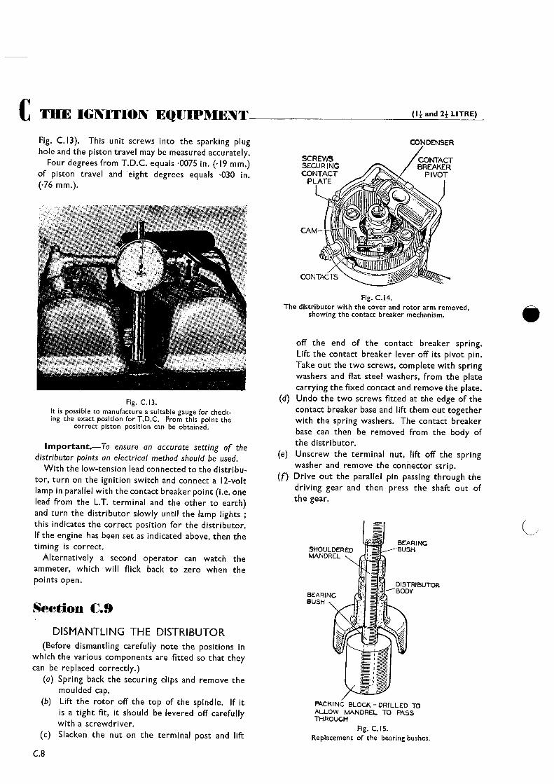
Fig. C. 13). This unit screws into the sparking plughole and the piston travel may be measured accurately.
Four degrees from T.D.C. equals 0075 in. (.19 mm.)of piston travel and •eight degrees equals 030 in.(.76 mm.).
Fig. C.13.It is possible to manufacture a suitable gauge for check-ing the exact position for T.D.C. From this point the
correct piston position can be obtained.
Important.—To ensure an accurate setting of thedistributor points an electrical method should be used.
With the low-tension lead connected to the distribu-tor, turn on the ignition switch and connect a 12-voltlamp in parallel with the contact breaker point (i.e. onelead from the L.T. terminal and the other to earth)and turn the distributor slowly until the lamp lightsthis indicates the correct position for the distributor.If the engine has been set as indicated above, then thetiming is correct.
Alternatively a second operator can watch theammeter, which will flick back to zero when thepoints open.
Section C.9
DISMANTLING THE DISTRIBUTOR(Before dismantling carefully note the positions in
which the various components are fitted so that theycan be replaced correctly.)
(a) Spring back the securing clips and remove themoulded cap.
(b) Lift the rotor off the top of the spindle. If itis a tight fit, it should be levered off carefullywith a screwdriver.Slacken the nut on the terminal post and lift(c)
C.8
Fig. C.14.The distributor with the cover and rotor arm removed,
showing the contact breaker mechanism.
off the end of the contact breaker spring.Lift the contact breaker lever off its pivot pin.Take out the two screws, complete with springwashers and flat steel washers, from the platecarrying the fixed contact and remove the plate.
(d) Undo the two screws fitted at the edge of thecontact breaker base and lift them out togetherwith the spring washers. The contact breakerbase can then be removed from the body ofthe distributor.
(e) Unscrew the terminal nut, lift off the springwasher and remove the connector strip.
(f) Drive out the parallel pin passing through thedriving gear and then press the shaft out ofthe gear.
Fig. C.15.Replacement of the bearing bushes.

(14 and 24 LITRE) THE IGNITION EQUiPMENT C(g) Lift the cam, automatic timing control and shaft
assembly from the distributor. Take out thescrew from inside the top of the cam spindleand lift the cam off. The automatic timingcontrol is then accessible.
Section C.10THE CONDENSER
The best method of testing the condenser is bysubstitution. Disconnect the original condenser andconnect a new one between the low-tension terminalof the distributor and earth.
Should a new condenser be necessary, it is advisableto fit a complete condenser and contact bracket plateassembly, but should a condenser only be available,care must •be taken not to overheat the condenserwhen soldering it in position.
Section C.lIFITTING NEW DISTRIBUTOR BUSHES(a) In order to ensure easy running of the distribu-
tor shaft whenthe shank has been rebushed, the•new bushes must be fitted so that they are incorrect alignment. The bushes must be fittedby means of a vertical drilling machine or handpress, using a mandrel and a packing block ofthe type shown.
(b) Fit the mandrel in the drilling machine or handpress and place the distributor body in aninverted position on the table below it.
(c) To remove the bushes, a sleeve must be fittedover the mandrel to build it up to the requiredsize: With this sleeve fitted in position, forcethe old bushes out of the shank by applying asteady pressure. Before new bushes are fittedthey should be allowed to soak for twenty-fourhours in thin engine oil.
(d) Take the sleeve off the mandrel. Place one ofthe longer bushes on the mandrel, then thedistributor body in an inverted position andfinally one of the smaller bushes.
(e) Locate the end of the mandrel through thepacking piece and press the mandrel down-wards, taking care that both bushes enter thedistributor shank squarely. Continue forcingthe bushes into the shank until the mandrelreaches the end of its travel.
(f) After fitting, the bushes must not be openedout by reamering or any other means, as thiswould tend to impair the porosity of thebushes, and so prevent effective lubricationfrom being obtained.
Section C.12REASSEMBLING THE DISTRIBUTOR
Note.—Before reassembly, the automatic advancemechanism, distributor shaft, and the portion of the shafton which the cam fits must be lubricated with thin,clean engine oil.
(a) Assemble the automatic timing control, takingcare that the parts are fitted in their originalpositions and that the control springs are notstretched. Two holes are provided in eachtoggle ; the springs must be fitted to the innerhole in each case. Place the cam on its spindleand secure by tightening the locking screw.
(b) Fit the shaft in its bearings and replace thedriving member. Remembering that the smalloffset of the driving tongue lies towards thefront of the engine when the slot for the
Fig. C.16.The distributor points are best cleaned by removingthe rocker-arm from its pivot and dressing the points
with a stick of carborundum as shown.
rotating arm in the cam faces towards thecentre of the engine (or towards the condenserin the distributor body) fit the driving pin andburr over the collar each side, to retain it inposition, with a suitable punch.
(c) Place the contact breaker base in position onthe distributor body and secure it by replacingthe two screws. A spring washer must befitted under each of the screw heads, and thescrews must be fully tightened.
(d) Place the end of the connector strip over thecondenser terminal post, refit the spring washerand secure it by tightening the terminal nut.
(e) Position the plate carrying the fixed contacton the contact breaker base and secure it byreplacing and lightly tightening the two screws,placing a spring washer and flat steel washerunder the heads of each of the screws. Placethe insulating washer over the contact breakerpivot pin and position the contact breaker
C.9
(14 and 24 LITRE)C THE IGNITION EQUIPMENT
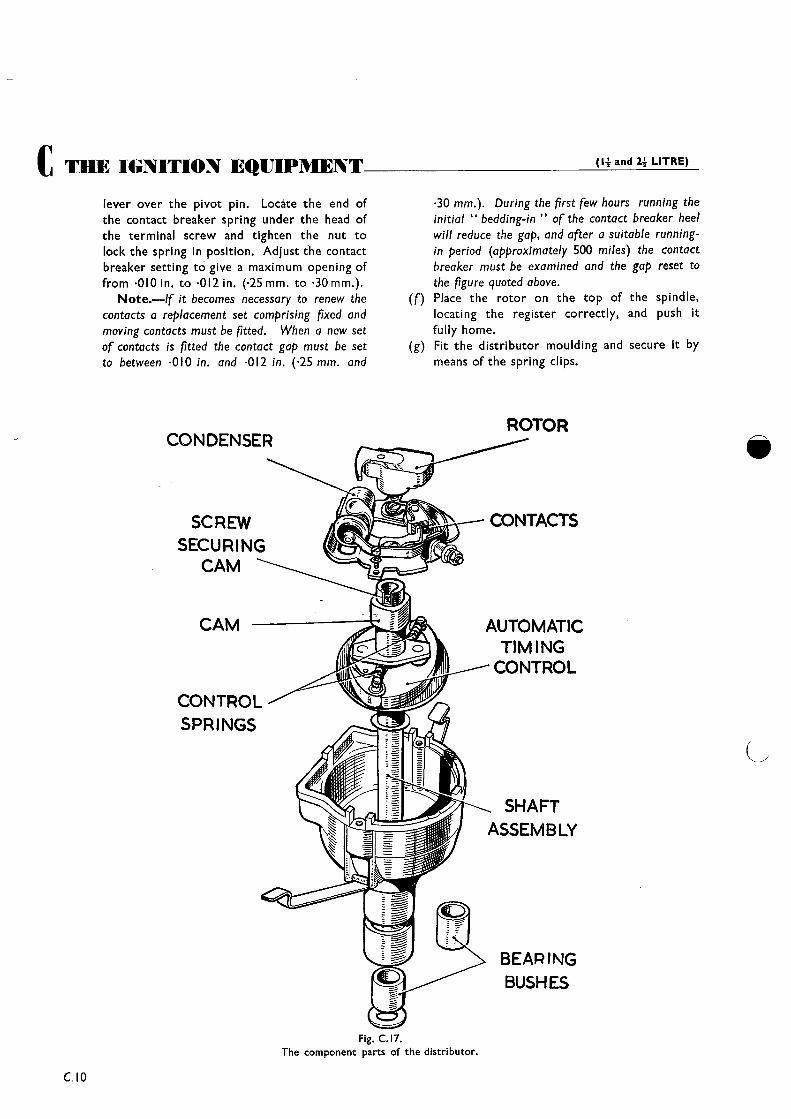
lever over the pivot pin. Locate the end ofthe contact breaker spring under the head ofthe terminal screw and tighten the nut tolock the spring in position. Adjust the contactbreaker setting to give a maximum opening offrom •010 in. to ~0l2in. (.25mm. to .30mm.).
Note.—lf it becomes necessary to renew thecontacts a replacement set comprising fixed andmoving contacts must be fitted. When a new setof contacts is fitted the contact gap must be setto between ~0l0 in. and .012 in. (.25 mm. and
CAM
CONTROLSPRINGS
•30 mm.). During the first few hours running theinitial “bedding-in of the contact breaker heelwill reduce the gap, and after a suitable running-in period (approximately 500 miles) the contactbreaker must be examined and the gap reset tothe figure quoted above.
(f) Place the rotor on the top of the spindle,locating the register correctly, and push it
fully home.(g) Fit the distributor moulding and secure it by
means of the spring clips.
AUTOMATICTIMINGCONTROL
SHAFTASSEMBLY
Fig. C.17.The component parts of the distributor.
CONDENSER
SCREWSECURINGCAM
ROTOR
CONTACTS
BEAR!NGBUSHES
Cl0
(14 and 24 LITRE) TIlE IGNITION EQUIPMENT CSection C.13
DISTRIBUTORS WITH “HIGH-LIFT”CAMS
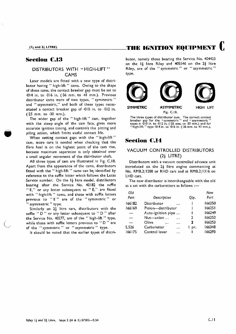
Later models are fitted with a new type of distri-butor having “ high-lift cams. Owing to the shapeof these cams, the contact breaker gap must be set to014 in. to .016 in. (.36 mm. to 41 mm.). Previousdistributor cams were of two types, “ symmetricand “ asymmetric,” and both of these types neces-sitated a contact breaker gap of 010 in. to 012 in.(.25 mm. to ~30mm.).
The wider gap of the “ high-lifts’ cam, togetherwith the steep angle of the cam face, gives moreaccurate ignition timing, and controls the pitting andpiling action, which limits useful contact life.
When setting contact gaps with the “ high-liftcam, more care is needed when checking that thefibre heel is on the highest point of the cam rise,because maximum separation is only obtained overa small angular movement of the distributor shaft.
All three types of cam are illustrated in Fig. C.18.Apart from the appearance of the cams, distributorsfitted with the “ high-lift “ cams can be~ identified byreference to the suffix letter which follows the LucasService number. On the 14 litre model, distributorsbearing after the Service No. 40182 the suffix
or any letter subsequent to ‘‘ ~ are fittedwith “ high-lift “ cams, and those with suffix lettersprevious to E are of the symmetric~~ or
asymmetric type.Similarly on 24 litre cars, distributors with the
suffix “ D ‘~ or any letter subsequent to “ D “ afterthe Service No. 40277, are of the “ high-lift type,while those with suffix letters previous to “ D “ areof the “ symmetric or “ asymmetric “ type.
It should be noted that the earlier types of distri-
butor, namely those bearing the Service No. 404425on the 14 litre Riley and 405546 on the 24 litreRiley, are of the “ symmetric or “ asymmetrictype.
LYMMETRIC ASYMMETRIC HIGH LIFTFig. C.18.
The three types of distributor cam. The correct contactbreaker gap for the “symmetric’s and “asymmetrictypes is •010 in. to ~0l2 in. (.25 mm. to ~30mm.) and for“high-lift” type 014 in to 016 in (.36 mm. to •41 mm.).
Section C.14
VACUUM CONTROLLED DISTRIBUTORS(24 LITRE)
Distributors with a vacuum controlled advance unitIntroduced on the 24 litre engine commencing atNo. RMB.2/1288 or RHD cars and at RMB.2/1316 onLHD cars.
The new distributor is interchangeable with the oldas a set with the carburetters as fo!lows
OldPart
166182166169
S.526166175
DescriptionDistributorPinion—distributorAuto-ignition pipeNut—unionOliveCarburetterControl lever
Qty.
22
I pr.
NewPart
166250166251166249166252166253166348166293
Riley 14 and 24 Litre, Issue 2 (H & E) 87302—5/54 C.l I