installation and operating instructions for aqua … and operating instructions for ... • on...
TRANSCRIPT
Installer: Please leave manual with homeowner.Homeowner: Please retain for operation and future maintenance instructions.
6888931 0609
Installation and Operating Instructions For
Aqua-Pure® AP-DWS1000 & AP-DWS1000 LFDrinking Water Filtration Systems


SAFETY INFORMATION
EXPLANATION OF SIGNAL WORD CONSEQUENCES
WARNING
Read, understand, and follow all safety information contained in these in-structions prior to installation and use of the AP-DWS1000 & AP-DWS1000 LF Drinking Water Filtration Systems. Retain these instructions for future reference.
Intended use:The Aqua-Pure® AP-DWS1000 & AP-DWS1000 LF Drinking Water Filtration Systems are intended for use in filtering drinking water in residential locations and have not been evalu-ated for other uses. These systems are typically installed beneath or near a kitchen sink, and it is recommended that the installation be performed by a qualified installation specialist or a licensed plumber.
CAUTION
WARNINGIndicates a potentially hazardous situation, which, if not avoided, could result in death or serious injury and/or property damage.
Indicates a potentially hazardous situation, which, if not avoided, may result in property damage.
To reduce the risk associated with choking: •Do not allow children under 3 years of age to have access to small parts during the
installation of this product.
To reduce the risk associated with ingestion of contaminants: •Do not use with water that is microbiologically unsafe or of unknown quality without
adequate disinfection before or after the system.
To reduce the risk associated with a hazardous voltage due to an installer drilling through existing electric wiring or water pipes in the area of installation: •Do not install near electric wiring or piping which may be in the path of a drilling tool
when selecting the position to mount the filter bracket.
2
CAUTION
IMPORTANT NOTES
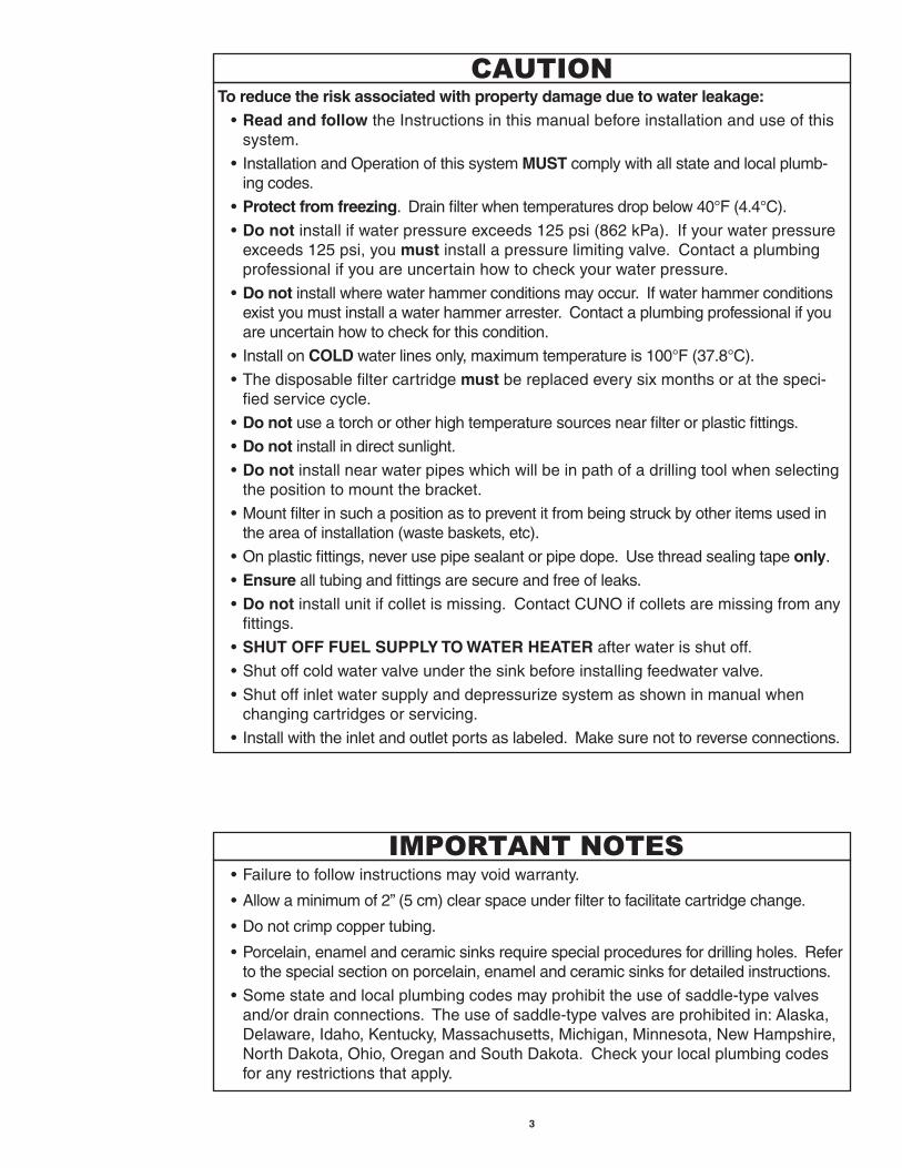
To reduce the risk associated with property damage due to water leakage: •Read and follow the Instructions in this manual before installation and use of this
system.
• InstallationandOperationofthissystemMUST comply with all state and local plumb-ing codes.
•Protect from freezing. Drain filter when temperatures drop below 40°F (4.4°C).
•Do not install if water pressure exceeds 125 psi (862 kPa). If your water pressure exceeds 125 psi, you must install a pressure limiting valve. Contact a plumbing professional if you are uncertain how to check your water pressure.
•Do not install where water hammer conditions may occur. If water hammer conditions exist you must install a water hammer arrester. Contact a plumbing professional if you are uncertain how to check for this condition.
• InstallonCOLD water lines only, maximum temperature is 100°F (37.8°C).
•Thedisposablefiltercartridgemust be replaced every six months or at the speci-fied service cycle.
•Do not use a torch or other high temperature sources near filter or plastic fittings.
•Do not install in direct sunlight.
•Do not install near water pipes which will be in path of a drilling tool when selecting the position to mount the bracket.
•Mountfilterinsuchapositionastopreventitfrombeingstruckbyotheritemsusedinthe area of installation (waste baskets, etc).
•Onplasticfittings,neverusepipesealantorpipedope.Usethreadsealingtapeonly.
•Ensure all tubing and fittings are secure and free of leaks.
•Do notinstallunitifcolletismissing.ContactCUNOifcolletsaremissingfromanyfittings.
•SHUT OFF FUEL SUPPLY TO WATER HEATER after water is shut off.
•Shutoffcoldwatervalveunderthesinkbeforeinstallingfeedwatervalve.
•Shutoffinletwatersupplyanddepressurizesystemasshowninmanualwhenchanging cartridges or servicing.
• Installwiththeinletandoutletportsaslabeled.Makesurenottoreverseconnections.
•Failuretofollowinstructionsmayvoidwarranty.
•Allowaminimumof2”(5cm)clearspaceunderfiltertofacilitatecartridgechange.
•Donotcrimpcoppertubing.
•Porcelain,enamelandceramicsinksrequirespecialproceduresfordrillingholes.Referto the special section on porcelain, enamel and ceramic sinks for detailed instructions.
•Somestateandlocalplumbingcodesmayprohibittheuseofsaddle-typevalvesand/or drain connections. The use of saddle-type valves are prohibited in: Alaska, Delaware,Idaho,Kentucky,Massachusetts,Michigan,Minnesota,NewHampshire,NorthDakota,Ohio,OreganandSouthDakota.Checkyourlocalplumbingcodesfor any restrictions that apply.
3
4
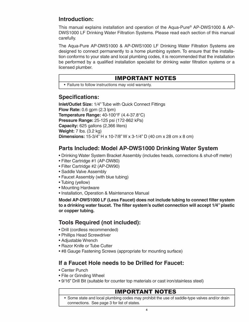
Introduction:This manual explains installation and operation of the Aqua-Pure® AP-DWS1000 & AP-DWS1000 LF Drinking Water Filtration Systems. Please read each section of this manual carefully.
The Aqua-Pure AP-DWS1000 & AP-DWS1000 LF Drinking Water Filtration Systems are designed to connect permanently to a home plumbing system. To ensure that the installa-tion conforms to your state and local plumbing codes, it is recommended that the installation be performed by a qualified installation specialist for drinking water filtration systems or a licensed plumber.
Specifications:Inlet/Outlet Size:1/4”TubewithQuickConnectFittingsFlow Rate: 0.6 gpm (2.3 lpm)Temperature Range: 40-100°F (4.4-37.8°C)Pressure Range: 25-125 psi (172-862 kPa)Capacity: 625 gallons (2,366 liters)Weight: 7 lbs. (3.2 kg)Dimensions: 15-3/4”Hx10-7/8”Wx3-1/4”D(40cmx28cmx8cm)
Parts Included: Model AP-DWS1000 Drinking Water System•DrinkingWaterSystemBracketAssembly(includesheads,connections&shut-offmeter)•FilterCartridge#1(AP-DW80)•FilterCartridge#2(AP-DW90)•SaddleValveAssembly•FaucetAssembly(withbluetubing)•Tubing(yellow)•MountingHardware•Installation,Operation&MaintenanceManual
Model AP-DWS1000 LF (Less Faucet) does not include tubing to connect filter system to a drinking water faucet. The filter system’s outlet connection will accept 1/4” plastic or copper tubing.
Tools Required (not included):•Drill(cordlessrecommended)•PhillipsHeadScrewdriver•AdjustableWrench•RazorKnifeorTubeCutter•#8GaugeFasteningScrews(appropriateformountingsurface)
If a Faucet Hole needs to be Drilled for Faucet:•CenterPunch•FileorGrindingWheel•9/16”DrillBit(suitableforcountertopmaterialsorcastiron/stainlesssteel)
• Failuretofollowinstructionsmayvoidwarranty.
IMPORTANT NOTES
• Somestateandlocalplumbingcodesmayprohibittheuseofsaddle-typevalvesand/ordrainconnections. See page 3 for list of states.
IMPORTANT NOTES

5
1) Install Drinking Water System Faucet (Refer to Figure 4, Page 11):
Instructions for drilling 9/16” diameter hole through counter top or stainless steel sinkA. Locateareatobedrilled.Markcenteroftheholewithcenterpunch.B. Drillholewith9/16”drillbitsuitabletocountertopmaterialsorcastiron/stainlesssteel.C. With grinding wheel or file, smooth out any rough edges.
Installing the FaucetA. Slide the following parts in the order specified up blue tubing and threaded brass stem: 1. Stainless steel bezel 2. Large rubber washerB. Next,feedbluetubingandfaucetstemdownthroughfaucetmountinghole.C. From underneath sink, assemble the black spacer, star washer and hex nuts as shown
(see Figure 4, Page 11) onto the threaded brass stem and tighten by hand.D. With a padded adjustable wrench, turn the faucet base (above the counter) to the right
(clockwise)tosecurelyfasten.Removepieceofplastictubingfrombase.E. Insert faucet neck onto base until seated and align over sink.
2) Mount SystemDetermine undersink mounting location
A. Markholesonmountingsurfaceusingholesonbracketasguides.B. Drillstarterholesintomountingsurface.C. Hangunitontomountingsurfacebyfasteningwoodscrewsthroughbackplateofbracket.
3) Install Feedwater Valve (Refer to Figure 5, Page 11)
A. Most sinks use 3/8” copper tubing. Connect the saddle valve as shown in Figure 5,Page11.Thebacksaddlebracketcanbereversedforsmallerpipesizes(7/16”to1/2”).Tighten screws evenly and firmly, brackets should be parallel.
To reduce the risk associated with a hazardous voltage due to an installer drilling through
existing electric wiring or water pipes in the area of installation: •Do not install near electric wiring or piping which may be in the path of a drilling tool when
selecting the position to mount the filter bracket.
To reduce the risk associated with property damage due to water leakage: • Shutoffcoldwatervalveunderthesinkbeforeinstallingfeedwatervalve. • InstallationandUseMUST comply with all state and local plumbing codes.
CAUTION
WARNING
• Porcelain,enamelandceramicsinksrequirespecialproceduresfordrillingholes.Refertothespecial section on porcelain, enamel and ceramic sinks for detailed instructions.
• Thedrinkingwatersystemfaucetshouldbelocatedonaflatsurface,convenientlylocatednearthesink,sothatitemptiesintothesink.Mostsinkshavepre-drilledholesdesignatedforspray-ers, soap dispensers and other accessories. If your sink does not have an extra hole, then a 9/16”diameterholemustbedrilled.
IMPORTANT NOTES
• Allowaminimumof2”(5cm)clearspaceunderfiltertofacilitatecartridgechange.IMPORTANT NOTES

6
B. Topiercesoft copper tubing, turnhandle to the right (clockwise)several timesuntil itstops. The valve is now closed. Turning the handle to the left (counterclockwise) will open the valve.
C. Assemble insert, plastic sleeve and compression nut as shown onto yellow tubing and fasten securely to saddle valve.
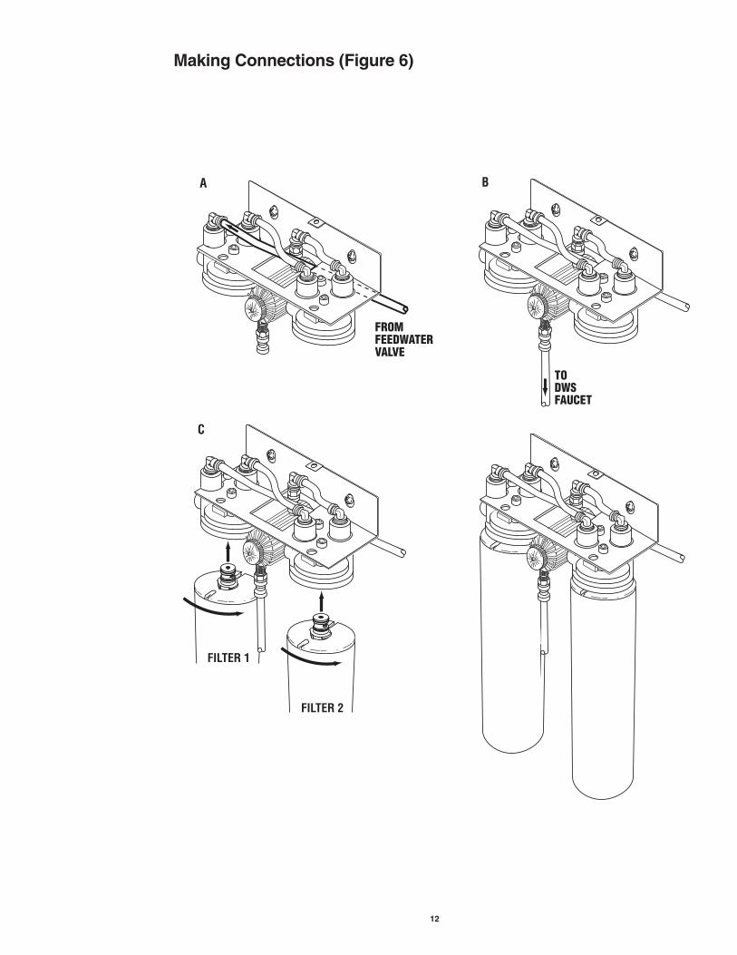
4) Making Connections (Refer to Figure 6, Page 12)A. Connectyellow1/4”tubingfromsaddlevalvetothe“Push-In”fittingontheleftsideofthe
bracketassembly.THEYELLOWTUBEMUSTGOUPANDTHROUGHTHEBASEOFTHEBRACKET.
B. Connect theblue1/4” tubing fromthebaseof the faucet to the“Push-In”fittingat-tached to the base of the shut-off meter.
Installing Filter Cartridge & Replacing Filter CartridgesC. Inordertoensureproperperformance,itisessentialthat“Filter1”beinstalledontheleft
and“Filter2”ontherightsideofthebracketassembly.Usethecolor/numbercodedlabelstomatch“Filter1”cartridgewith“Filter1”head.
D. Metershouldbesetat“Start”.
5) Test SystemA. Opencoldwatervalveunderthesink.B. Thesystemwillpressurize.Checkforleaks.Ifanyleaksarepresent,immediatelyturnoff
water and refer to the Troubleshooting Section.
6) Flush FilterA. Pressing down on the faucet lever will dispense water until you let go. Lifting up on the
lever will lock the faucet open.B. Flush5gallonsthroughsystem(approximately10minutes).Atthispoint,thewaterwill
run clear. In rare cases, it may take a week or more for the residual air bubbles to be completely eliminated.
C. The system installation is now complete and ready to serve filtered water.
Enjoy!
7) Procedure for Drilling Hole Through Porcelain/Enamel/Ceramic Sinks with Sheet Metal or Cast Iron BaseRecommended Tools: •VariableSpeedDrill •PorcelainCutterToolSet(9/16”size) •Plumber’sPutty
NOTE: It is important to understand this procedure before beginning.
To reduce the risk associated with property damage due to water leakage: • InstallationandUseMUST comply with all state and local plumbing codes.
CAUTION
• Besuretoinstalltubingsotherearenosharpbendsandinstallenoughtubingforeaseofser-vice.Refertotheencloseddiagram(Figure1,Page8)ontheuseof“Push-In”plasticfittings.
• Failuretoroutetheyellowtubingthroughthebracketwillnotallowprotectiveshroudtobefas-tened securely to the bracket.
IMPORTANT NOTES

7
1. The glassy layer of porcelain/enamel/ceramic must be scored through to the metal base creating a disc.
2. This disc must be removed while protecting the surrounding decorative coating against chipping or fracturing.
3. The base metal must be drilled through to complete the hole.
Procedure: A. Markcenterfor9/16”hole.B. Formadamofshallowputtyaroundholelocationandfillwithenoughwatertolubricate
carbide drill bit.C. Carefully drill pilot hole through porcelain/enamel/ceramic and base metal using a carbide
pilot drill. Always operate drill with light pressure at slow speed (300-400 rpm).D. Drillporcelain/enamel/ceramicusingspecial9/16”cuttingtool,makingcertainacomplete
ringhasbeencutthroughtothesink’smetalbase.E. Change to metal cutting drill bit and drill out the center of the ring, making sure not to
contact outer rim of decorative coating. Cut through metal sink base.
8) TroubleshootingWater leaks from threaded connection: Tighten fittings or hex nut until leak stops. If leaks persist, shut off water at the cold water
valve, remove threaded fittings, reapply PTFE tape around the fitting to the left (counter-clockwise), and screw back into head assembly or saddle valve.
Water leaks at quick connect fittings: Push tubing in as far as it will go. If leaking continues, shut off water at the cold water valve
and remove water line by pushing in on the connector collet while pulling the tubing away. Inspect tubing for cracks. If tubing is cracked, simply cut that portion away and re-insert tubing into quick connect fitting (see Figure 1, Page 8).
Water does not flow from the drinking water system faucet: Checktoseeifthemainwaterlinevalveisopen,allowingwatertoflowtothefilter.Ifwater
stilldoesnotflowfromthedrinkingwatersystemfaucet,makesurethefilter’sshut-offvalveisresetto“Start”.Also,checkforcrimpsorsharpbendsintheblueandyellowtubing.
NOTE: In rare cases, it may take a week or more for the residual air bubbles to be com-pletely eliminated.

8
Quick Connect Guide (Figure 1)
‘Push-In’ Tubing Connector(Quick Connect Fittings)
This product is outfitted with user friendly ‘Push-In’connectors. Properuseof thecon-nectors is shown in the diagrams. It is most important that the tubing selected for use with these connectors be of high quality, exact size and roundness and with no surface nicks or scratches. If it is necessary to cut the tubing, use a plastic tubing cutter or sharp razor knife. Makeacleansquarecut.Shouldaleakoccurata‘Push-In’connector, thecause isusuallydefective tubing.
To Fix: •Relievepressure •Releasetubing •Cutoffatleast1/4”fromend •Reattachtubing •Confirmconnectionisleakfree
To reduce the risk associated with property damage due to water leakage: • Ensure all tubing and fittings are secure and free of leaks. • Do notinstallunitifcolletismissing.ContactCUNOifcolletsaremissingfromanyfittings.
CAUTION
12
Grey Collet
Tube1 2 gnibuT esaeleR oT gnibuT hcattA oT
Push tubing straight in as far as it will go. Tubing must be inserted past o-ring and hit backstop. Pull tube to ensure it is secured.
Push in grey collet to release tubing. With collet held, pull tubing straight out.

9
Reference # Part # Description
1 69968-31 Self-PiercingWaterValve
2 36897-82* 1/4”InletYellowTubing(priceperft.)
3 55851-02 AP-DW80&AP-DW90CartridgeSet
4 36897-62* 1/4”OutletBlueTubing(priceperft.)
5 69888-42 Faucet
6 68841-21 Shroud
7 68871-01 Head
8 85-400201 UTCShroudMountingPin(notshown)
9 68845-31 3/8”NPTx1/4”Tube(Qty.4)
10 68873-31 1/4”NPTAdaptorx1/4”Tube(Qty.2)
11 74-3230404 1/4”Plug-InElbow
12 68870-33 MeteringValve
13 69804-34 MeteringValveScrew(Qty.4)
*Mustorderminimumof10ft(3m)
6
9
1312
41
10
2
7
3
5
3
11
AP-DWS1000 Parts List (Figure 2)

10
Stainless BezelRubber WasherCountertop
Plastic Backing SpacerStar WasherHex Nut
FILTER 1
FILTER 2
17" (43.2 cm)Minimum
2" (5 cm)Minimum
63
4
2
1
Standard Installation Overview
1. Install DWS Faucet2. Mount System
3. Install Feedwater Valve4. Making Connections
5. Test System6. Flush Filter (see
page 6, Step 6B of this manual for instructions)
3
1
4 5
6
2
Installation Overview (Figure 3)

11
Install Drinking Water System Faucet (Figure 4)
Stainless BezelRubber Washer
A
Stainless BezelRubber WasherCountertop
B
Stainless BezelRubber WasherCountertop
Plastic Backing SpacerStar WasherHex Nut
C
Stainless BezelRubber WasherCountertop
Plastic Backing SpacerStar WasherHex Nut
D
Install Feedwater Valve (Figure 5)
A B C
12
Making Connections (Figure 6)
FROMFEEDWATERVALVE
A
TODWSFAUCET
B
C
FILTER 1
FILTER 2

13
Cartridge Change Instructions (Refer to Corresponding Dia-grams Below)
1. Turn water supply off at saddle valve or at undersink cold water line, and remove protective shroud from bracket.
2. Resetshut-offmeterbypushinginknobandturningtotheright(clockwise)untilthearrowonthetopofthemeterbodyislinedupto“Start”.(Itisrecommendedthatthecartridgesbe replaced when the meter reads 625 gallons. The shut-off meter will shut water pres-suretothefaucetwhen625gallonsaredispensed.)Openfaucettodepressurizethesystem.
3. Lift red knob upward and hold.4. Turn cartridge to the left (counterclockwise) and gently pull straight down. Discard spent
cartridge. If system has not been properly depressurized, a small amount of water may discharge.Repeatforsecondcartridge.
5. Align tabs of the new cartridges with head and insert cartridge. Turn cartridge to the right (clockwise)untilaclickingsoundisheard.Thecartridgeisnowproperlyinstalled.Usethenumbercodedlabelstomatch“FILTER1”cartridgewith“FILTER1”head.Repeatwith“FILTER2”.
6. Turn on water at saddle valve or water line and check system for leaks. If leaks occur, check connections or repeat cartridge installation.
7. Flush5gallons throughsystem (approximately10minutes). Residualairmaycausetemporary cloudiness in water. Place protective shroud back on bracket.
2
5 7
3 4
To reduce the risk associated with property damage due to water leakage: • Thedisposablefiltercartridgemust be replaced every six months or at the specified ser-
vice cycle.
CAUTION

NOTES:
14

3M is a trademark of 3M Company.CUNO and Aqua-Pure are trademarks of 3M Company used under license.© 2009 3M Company. All rights reserved.
®
ynapmoc M3 aCUNO Incorporated
400 Research ParkwayMeriden, CT 06450 USA
Toll Free: 1-800-222-7880Worldwide: 203-237-5541
Fax: 203-238-8701www.aquapure.com • www.cuno.com
Limited One Year Warranty
CUNOIncorporatedwarrants thisProduct tobefreefromdefects inmaterialandwork-manship for one (1) year from the date of purchase. This warranty does not cover failures resulting from abuse, misuse, alteration or damage not caused by CUNO or failure tofollowinstallationanduseinstructions.IftheProductisdefectiveCUNOwillreplacetheProductorrefundyourProductpurchaseprice.CUNOwillnotbeliableforanyindirect,special, incidental, or consequential damages arising from the use of this Product. Some states do not allow the exclusion or limitation of incidental or consequential damages, so the above limitation may not apply to you. To obtain warranty service, mail your request to Warranty Claims, CUNO Incorporated, 400 Research Parkway, Meriden, CT 06450.Proof of purchase (original sales receipt) must accompany the warranty claim, along with a complete description of the Product, model number and alleged defect. This warranty gives you specific legal rights and you may have other rights which vary from state to state, or country to country.