installation instructions heat pipe - enerworks
TRANSCRIPT

Installation Instructions Heat PipeSolarthermal – Powerful – Long-living
Entwicklungs- & Vertriebs GmbH
R

2
Installation Instructions for:
HP (Heat Pipe) collector systems
General safety
Solar thermal panels generate heat when exposed to sunlight. All parts such as pipes, connectors, sensors, etc.
pose the risk of injury from hot surfaces. In addition, solar thermal systems are operated with overpressure.
When a solar thermal system is open, this can lead to leakage of steam or hot water. People who work on solar
thermal systems must take this into consideration and must wear protective clothing and follow safety procedures.
The vacuum tube sets are transported horizontally. They may be stacked on a maximum of 7 cartons.
Our mounting kits are valid for all snow load zones (except zone 3). In storm areas special static calculations must
be performed.
Safety notice:
Helmet, ear protection, and protective goggles must be worn! Safety gear against falling is necessary!
Vacuum tubes are only to be touched with gloves (gloves are enclosed).
Required tools:
Possible types of installation
Flat roof, facade, roof tile (tile), trapezoidal sheet metal roof, pitched roof, plate fold roof
Attention!
The collectors must be mounted so that the header is in position on top. Please note that the tubes must be alig-
ned to the sun! The collector set up angle should be min. 20° to max. 70°.
20°
70°

Entwicklungs- & Vertriebs GmbH
R
3
Installation Instructions for:
HP (Heat Pipe) collector systems
Wall and or facades-, trapezoidal sheet metal assembly
Set up of the hat profiles in the facade and collector elevation. When mounting on a wall or facade, the
hat profiles are to be installed vertically. Advice: when mounting the collectors flat on the roof or on facades, the
use of the collector stabilizer set is recommended. (Art.Nr.: 791029) Page 4
H = 1950 mm
A B C D E F G H750 75 150 220 600 450 300 1950
1500 300 370 450 900 750 600 19502250 450 520 600 1350 1200 1050 1950
HP10HP20HP30The slots allow deviations of + / - 30 mm.
EFG
BDC
A
HEADER
FOOTER
Befestigung an Wand oder Fassade
Befestigung auf Trapezblech
Mark, drill, set the dowels, fix the hat profile with key screw NW 13 mm, with trapezoidal sheet metal and
flat roofs with appropriate screws .
Trapezoidal sheet metal assembly / roof and wall:
Screw the hat profiles onto the profiled sheeting using self tapping drill screws
(gasket: silicone, etc.) Collector assembly as in all other types of fastening.
1 2 3
3a
Mounting to wall or facade
Mounting on trapezoidal sheeting

Installation Instructions for:
HP (Heat Pipe) collector systems
4
Collector stabilizer set:
Advice: When mounting on facades, the collector stabilizer set is to be installed according to the images and .
The collector stabilizer set is to be positioned optionally at the free long holes of the connection bar of the header
and footer.
Mounting sequence: First mount the header and footer based on the installation instructions as usual with the
corresponding collector connection set and afterwards mount the stabilizer.
1 2
1920 - 1960 mm
HEADER
FOOTER
Entwicklungs- & Vertriebs GmbH
R
5
Installation Instructions for:
HP (Heat Pipe) collector systems
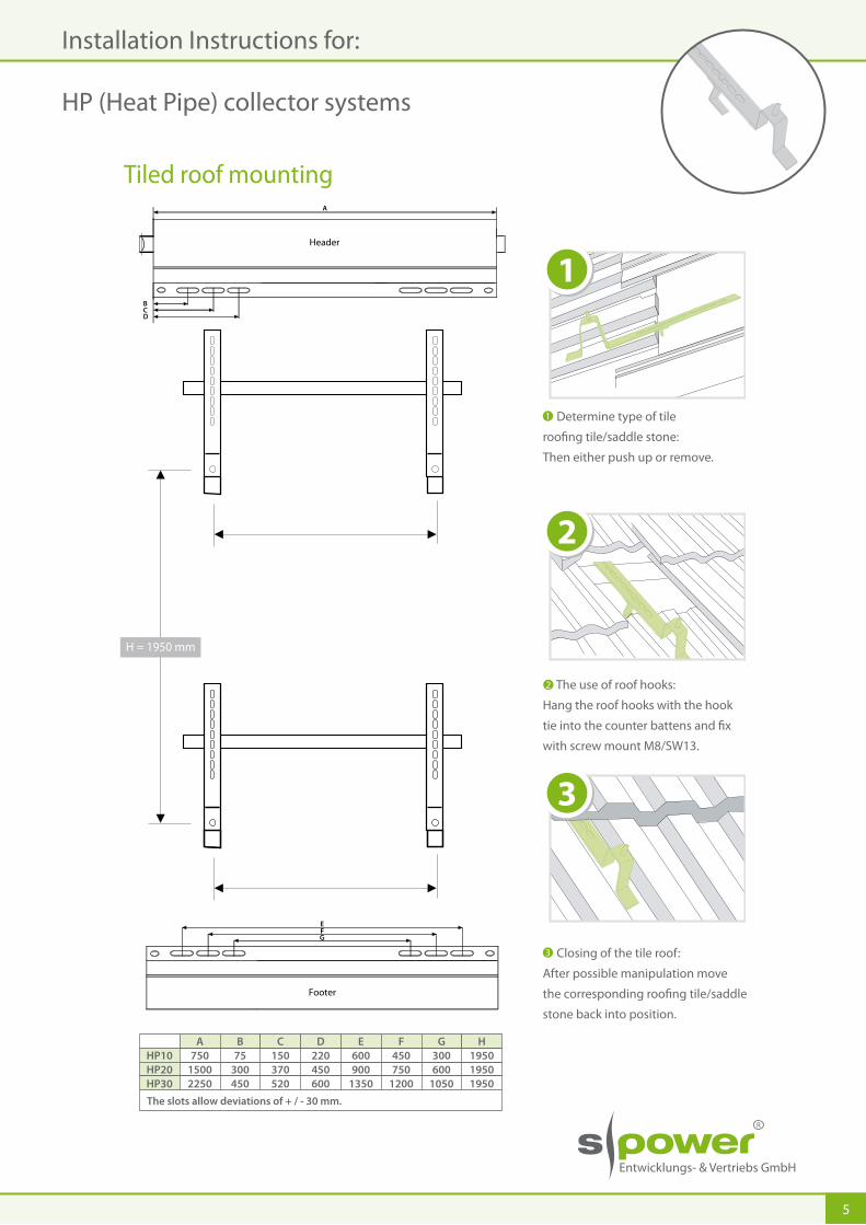
Tiled roof mounting
H = 1950 mm
Footer
Header
1
2
3
A B C D E F G H750 75 150 220 600 450 300 1950
1500 300 370 450 900 750 600 19502250 450 520 600 1350 1200 1050 1950
HP10HP20HP30The slots allow deviations of + / - 30 mm.
EFG
B
DC
A
Determine type of tile
roofing tile/saddle stone:
Then either push up or remove.
The use of roof hooks:
Hang the roof hooks with the hook
tie into the counter battens and fix
with screw mount M8/SW13.
Closing of the tile roof:
After possible manipulation move
the corresponding roofing tile/saddle
stone back into position.
1
2
3

Installation Instructions for:
HP (Heat Pipe) collector systems
6
Mounting with the flat roof mount frame
Mounting sequence for this particular fastening-parts kit:
Fastening of the holders-note the distance. (4x)
Installation of the side rail at the holders in front. (2x)
Installation of the elevation foot at the holders in the back. (2x)
Adjustment and connection of the side bar. (2x)
Installation and fixation of the rear bars. (1x)
Mounting the header and the foot rails onto the side rails. (2x)
A
B
C
D
E
F
Necessary tools:
Measuring tape, pencil, water level, impact drill with stone drill ø 10mm,
flat wrench SW 13, flat wrench SW17
AB
B
ca. 1500 mm
F
Measurement x
Type Heat Pipe
HP 10 240 - 660 mm
HP 20 540 - 960 mm
HP 30 985 -1410 mm
Measurement x A
F
A
C
C
A
D
D
F
F
E
Important! Set up and max. pressure of the base construction on flat roofs approved by DIN 1055/4.
ca. 1500 mm
For horizontal installation of the collectors only „weight per support A“!
Height over ground m up to 8Collector type 10er 20er 30erWeight per support A kg 40 60 80Weight per support B kg 50 70 90
Height over ground m up to 8-20Collector type 10er 20er 30erWeight per support A kg 55 75 95Weight per support B kg 65 85 105

Entwicklungs- & Vertriebs GmbH
R
7
Installation Instructions for:
HP (Heat Pipe) collector systems
Lining up collectors, connecting the header:
First, align a header, mount and tighten the mounting screws. Subsequently connect the following header with
the HP connector to the already mounted header and couple with slightly rotating movements and only a little
pressure. Check whether the connection snapped by pulling slightly.
In order to couple the following header, it may be necessary to rotate the header 90 ° up and then move the
header into position.
Important! Collectors must be mounted flush to each other, otherwise there may be leaks.
Coupling of headers together:
Check coupling when pulling slightly, position header on the roof hook and secure with bolt nut M8:
1
2
1
2
1
2

8
Installation Instructions for:
HP (Heat Pipe) collector systems
Mounting the support brackets:
Fastening nut M8 - with bolt +
When mounting multiple panels in one row, one has to ensure that the header and the support brackets are
mounted flush.
4 5
Subsequent slide the tubes in. Important! Spray rubber rings at the foot with a soap/water mixture,
so that the vacuum tubes can easily insert. Wear cotton gloves.6
Insert the HP tube with slightly rotating movements into the connection bracket in the header. Insert so far until
the tube-safety-rubber touches the header, then pull back approx. 5 mm.
Check the lock by lightly pulling.
8
7
8

Entwicklungs- & Vertriebs GmbH
R
9
Installation Instructions for:
HP (Heat Pipe) collector systems
9 10 11
1312
For all types of installation:
Mounting the cover for the support brackets:
Insert the cover in the roof connection. Rotate the cover at the support bracket.
Lock the cover into place.
9 10
11
Mounting the side cover:
Position the side cover and secure it with screws on the support bracket.12 13

10
Installation Instructions for:
HP (Heat Pipe) collector systems
Mounting the connector (flexible hose or rigid piping):
Mount the side cover onto the exit side of the collector and clip the connector with the sensor pocket onto it.
After that insert with slightly rotating movements the flexible hose or rigid piping.
Important! Check lock by pulling slightly.
Mount the side cover onto the entrance side of the collector and subsequently insert the flexible hose or rigid
piping with slightly rotating movements.
Important! Check lock by pulling slightly.
1514
Mounting the sensor:
Insert the sensor and connect to the shrink hose. Shrink the shrink hose with a heating source or surround it with
attached protective tape.
Attention!
With the use of the rigid piping the fixed point of the pipeline should be determined in such a way that a suffici-
ent expansion of the collector header tube is possible.
14
15

Entwicklungs- & Vertriebs GmbH
R
11
Installation Instructions for:
HP (Heat Pipe) collector systems
Operating pressure:
Operating pressure = P0
Refer to example
TEST:
min.: 1,5 x P0 bar | 15 min.
max.: 5,5 bar | 15 min.
The operating pressure (min. operating pressure) of the system Po needs to be set in cold condition (20° C) in a
way that a pressure of 1,5 bar will develop at the height of the collector (header).
Example:
The collector was mounted h=10m above the expansion vessel.
P0 = (h x 0,1) + 1,5 bar
P0 = (10 x 0,1) + 1,5 bar
P0 = 2,5 bar
When in pressure less condition, the pre-pressure of expansion vessel needs to be set between 0,3 - 0,5 bar
below the system pressure P0.

12
Installation Instructions for:
HP (Heat Pipe) collector systems
Mounting dimensions HP collectors
B
DC
A
A B C D E F G H750 75 150 220 600 450 300 1950
1500 300 370 450 900 750 600 19502250 450 520 600 1350 1200 1050 1950
HP10HP20HP30The slots allow deviations of + / - 30 mm.
EFG
H
Header
Footer
6030 30
Example to determine the roof hooks – The position with 3 HP20 collectors
(medium long hole from roof hook to roof hook)
Hooks 1: measure C ; Hooks 2: measure F ; Hooks 3: measure C+C ; Hooks 4: measure F ;
Hooks 5: measure C+C ; Hooks 6: measure F
Hooks 1: 370 mm; Hooks 2: 750 mm; Hooks 3: 740 mm; Hooks 4: 750 mm;
Hooks 5: 740 mm; Hooks 6: 750 mm
The hooks for the footer are mounted symmetrically with the distance: dimension H.

Entwicklungs- & Vertriebs GmbH
R
13
Installation Instructions for:
HP (Heat Pipe) collector systems
Collector connections:
Attention!
Always install the sensors at the feed-in side of the collector (right hand side).
Possible connections for one collector:
sensor sensor
sensor sensorRL VL VL RL
RL
VL VL
RL
Possible connections for various horizontal installed collectors in a row (max. 70 tubes):
sensor
VL RL
sensor
RL VL
Possible connections for various horizontal installed collectors in a row and parallel (max. 70 tubes):
When connecting the collectors in parallel, attention has to be paid to identical seize (quantity of vacuum
tubes) and a clean connection based on „Tichelmann“.
RLVL RL
sens
or
RL
Possible connections for various collectors connected vertically in a row and parallel (max. 70 tubes):
When connecting the collectors in parallel, attention has to be paid to identical seize (quantity of vacuum
tubes) and a clean connection based on „Tichelmann“.
sensor
RL
sensorVL
RL
VL
RL
VLsensor
The air chamber/ air pot must always be installed at the highest point at
the feading side of the solar system (mandatory):
VL
inside

14
Installation Instructions for:
HP (Heat Pipe) collector systems
Check list:
Important points which must be noted:
1. Insert the vacuum tube with slightly rotating movements into the header.
• Remove the safety cap from the vacuum tube.
• Check connection by pulling slightly.
• Spray the vacuum tube with a soap-water mixture, this eases the installation of the tubes.
• Wear cotton gloves.
2. Attention! Do not use any automated exhaust fan with the solar system!
• Frequently occurring errors, because it is very common with standard furnace systems.
• Automated exhaust fans can be destroyed with high temperatures.
• Heat carrier fluid leaks, therefor the freezing protection is not guaranteed.
• Operational capability of the system is not guaranteed anymore. Use air chamber/air pot with a manual air-vent screw.
3. The heat carrier fluid must be filled using an electrical flush pump/solar filling station. Minimum flushing time
up to 30 min. Please make sure that the heat carrier fluid does not contain any air pockets.
The filling amount depends on the quantity of the installed collectors and the length of the pipes.
Guidelines for the filling quantity, refer to point 4.
4. Program the solar station to a sufficient volume stream of the heat carrier fluid! The regulated volume stream
must be set up in the TDC3-controller (ltr./h).
5. For safe operation of the solar expansion vessel a solar line vessel is to be used.
* Volume stream 40 - 45 l/m2/h (aperture area)
Tube quantities 30
Heat carrier�uidVolume stream *
Heat carrier�uidS-Sol VT50 (ca.)
40 50 60 70 80 100 120 14020
2,00-2,50l/min.
20kg
2,65-3,40l/min.
30kg
3,30-4,25l/min.
35kg
4,00-5,00l/min.
40kg
4,65-5,95l/min.
45kg
5,30-6,80l/min.
45kg
6,60-8,50l/min.
50kg
8,00-10,00l/min.
60kg
9,25-11,75l/min.
65kg
1,35-1,70l/min.
15kg
Attention!
We point out explicitly that the heat carrier fluid used in the system must be S-Sol VT50/VT100 or an alternative
tested by us in order to guarantee a long term safe operation of the solar system.
Maintenance direction
• The anti-freeze content of the heat carrier fluid must be checked annually!
• The safety devices (safety vent and expansion vessel) must be checked annually!
• The functioning of the control unit and all electronic components must be checked on a regular basis!

Entwicklungs- & Vertriebs GmbH
R
15
Installation Instructions for:
HP (Heat Pipe) collector systems
Pressure loss curve HP10
6. The below shown pressure loss curve is based on a 10 tube HP collector. In order to determine
the pressure loss of an entire collector field, the pressure loss needs to be multiplied by the quantity
per 10 HP tubes.
Example: Collector field with 60 HP tubes in one row:
Volume stream 60 HP tubes (as of chart 4 page 14): x = 4,5 ltr/min = 270 ltr/h
Druckverlust: y = 0,0002916*x² + 0,0060511*x
y = 0,0002916 * (270*270) + 0,0060511 * 270
y = 21,26 + 1,63
y = 22,89 mbar/10 HP tubes
y = 22,89 mbar x 6
y = 137,36 mbar/60 HP tubes
7. Dimensioning the expansion vessel:
Tube quantities 30 40 50 60 80 100 120 140
5 l 5 l 5 l 12 l
70
12 l 12 l 18 l 18 l 18 lSolar line vessel
Solar expansion vessel
20
5 l
18 l 25 l 25 l 25 l 35 l 35 l 50 l 50 l 80 l18 l
8. The water tank must be dimensioned between 50 l und 70 l/m2 gross collector area.
9. In case that no s-power control unit is used, the alternative controller needs to feature a vacuum
tube collector function.
10. The pipes used in the solar system must be sufficiently insolated.
11. The collector field must be grounded against lightning strike according
to the local regulations.

Entwicklungs- & Vertriebs GmbH
R
Industriestraße 24-2749716 MeppenGermany
Fon: + 49 5931 88388-0Fax: + 49 5931 88388-99
E-Mail: [email protected]
www.s-power.de Erro
rs a
nd o
mis
sion
s exc
epte
d. E
ditio
n 08
.12