innovative use of flowable fill for short-span bridge
TRANSCRIPT

Innovative Use of Flowable Fill for Short-Span Bridge Rehabilitation
By
James S. Davidson and Brian Copham Department of Civil and Environmental Engineering
The University of Alabama at Birmingham Birmingham, Alabama
Fred M. Gauntt III and Thomas C. Grimes
Shelby County Highway Department Columbiana, Alabama
Prepared by
UTCA University Transportation Center for Alabama
The University of Alabama, The University of Alabama in Birmingham, and The University of Alabama in Huntsville
UTCA Report Number 01218 August 30, 2002
ii
Technical Report Documentation Page
1. Report No FHWA/CA/OR-
2. Government Accession No. 3. Recipient Catalog No.
5. Report Date
March 31, 2002
4. Title and Subtitle
Innovative Use of Flowable Fill for Short-Span Bridge Rehabilitation 6. Performing Organization Code
7. Authors
James S. Davidson, Fred M. Gauntt III, Thomas C. Grimes, and Brian Copham
8. Performing Organization Report No.
UTCA Report 01218
10. Work Unit No.
9. Performing Organization Name and Address Department of Civil & Environmental Engineering The University of Alabama at Birmingham 1075 13th Street South Birmingham, AL 35294-4440
11. Contract or Grant No. DTR598-G-0028
13. Type of Report and Period Covered Final Report; January 1, 2001 – March 31, 2002
12. Sponsoring Agency Name and Address University Transportation Center for Alabama The University of Alabama P.O. Box 870205 Tuscaloosa, AL 35487-0205
14. Sponsoring Agency Code
15. Supplementary Notes 16. Abstract
This project investigated the use of a liquid concrete-like material, commonly referred to as flowable fill, to rehabilitate short span bridges and culverts commonly under the jurisdiction of local governments. The various methods in which this material can be used for bridge rehabilitation were explored and evaluated. The project entailed a comprehensive investigation into how other states have used flowable fill for bridge rehabilitation, study of a large-scale culvert -bridge rehabilitation conducted by the Alabama Department of Transportation Fourth Division near Wadley, Alabama, and four field demonstrations in Shelby County, Alabama. The study included the determination and discussion of the material properties of the flowable fill used in the demonstration projects, the development of methodology for bridge rehabilitation using flowable fill, and a costs and benefits analysis. The study found that there are several very important advantages offered by the use of flowable fill as backfill material for bridge rehabilitation including (1) cost efficiency, (2) expediency in returning traffic flow to normal, and (3) enhanced structural integrity and safety. Construction costs were found to decrease by approximately 40-50% compared to total replacement in most cases. The need to construct expensive detour bridges was eliminated. High-volume ash flowable fill not only makes use of a material that would otherwise be deemed a useless by-product material, it proved to be a valuable construction material with numerous applications which were not limited to its use as backfill for liner construction. Since the benefits of using the techniques demonstrated in the project were very evident, the project report was written to serve as an initial guide and tool to begin using flowable fill as a viable construction material in highway culvert and bridge replacement.
17. Key Words
Bridge management, bridge replacement, concrete, infrastructure, inspection, local government, transportation safety, flowable fill
18. Distribution Statement
19. Security Classify (of this report)
Unclassified
20. Security Classif. (of this page)
Unclassified
21. No of Pages 22. Price
Form DOT F 1700.7 (8-72)
iii
Contents
Contents ..............................................................................................................................iii Tables ...................................................................................................................................v Figures.................................................................................................................................vi Executive Summary...........................................................................................................vii 1.0 Introduction ..........................................................................................................1
1.1 General.........................................................................................................1 1.2 Objectives.....................................................................................................1 1.3 Scope ..........................................................................................................2 1.4 Methodology ................................................................................................2
2.0 Background ..........................................................................................................3 2.1 Flowable Fill Definitions .............................................................................3 2.2 Flowable Fill Benefits ..................................................................................3 2.1.1 Availability ......................................................................................3
2.2.2 Placement .........................................................................................4 2.2.3 Compaction......................................................................................4 2.2.4 Worker Safety..................................................................................4 2.2.5 Recycling Material...........................................................................4 2.2.6 Reduced Inspection..........................................................................4
2.3 Flowable Fill Uses .......................................................................................5 2.3.1 Backfill.............................................................................................5 2.3.2 Highway Surface Repair ..................................................................5 2.3.3 Structural Fill ...................................................................................5 2.3.4 Base Material ...................................................................................5 2.3.5 Conduit Bedding ..............................................................................5 2.3.6 Erosion Prevention...........................................................................6 2.3.7 Filling Voids ....................................................................................6 2.4 Bridge Rehabilitation...................................................................................6
2.4.1 Restoring Using Liners ....................................................................6 2.4.2 Bridge Backfilling............................................................................7 2.4.3 Culvert Backfilling...........................................................................7
2.5 Flowable Fill Uses in Other States for Bridge Rehabilitation .....................7 2.5.1 Iowa..................................................................................................8 2.5.2 Colorado...........................................................................................8 2.5.3 Texas ................................................................................................8
2.6 Review of State Specifications for Flowable Fill ........................................8 2.6.1 Tennessee .........................................................................................9 2.6.2 Mississippi .......................................................................................9 2.6.3 Ohio..................................................................................................9 2.6.4 Delaware ........................................................................................10
iv
Contents (continued) 2.6.5 Maryland ........................................................................................10 2.6.6 Kentucky........................................................................................10 2.6.7 Virginia ..........................................................................................11 2.6.8 New York .......................................................................................11 2.6.9 Illinois ............................................................................................11 2.6.10 Michigan ........................................................................................11 2.6.11 Lawrence, Kansas ..........................................................................12 2.6.12 Georgia...........................................................................................12 2.6.13 Colorado.........................................................................................13 2.6.14 Albuquerque, New Mexico ............................................................13 2.6.15 Missouri .........................................................................................13 2.6.16 Florida ............................................................................................13 2.6.17 South Carolina................................................................................14 2.6.18 Oklahoma .......................................................................................14 2.6.19 Iowa................................................................................................15 2.6.20 Indiana ............................................................................................15 2.6.21 Alabama .........................................................................................16
2.7 Cost Analysis .............................................................................................16 3.0 The Wadley Alabama Field Demonstration ..........................................................18 3.1 General ......................................................................................................18 3.2 Construction...............................................................................................18
3.2.1 Site Preparation..............................................................................18 3.2.2 Placement of Pipe...........................................................................20 3.2.3 Forming Around the Ends..............................................................20 3.2.4 Bracing Installation........................................................................23 3.2.5 Placement of Flowable Fill ............................................................23 3.2.6 Third Pipe Installation....................................................................24
3.3 Material Test Results .................................................................................24 3.4 Assessment and Analysis ..........................................................................26
3.4.1 Cost Analysis .................................................................................26 3.4.2 Owner Input ...................................................................................27
4.0 Shelby County Demonstration Projects ................................................................29 4.1 General ......................................................................................................29
4.2 Shelby County Project Replacing Metal Pipe Culvert...............................29 4.3 Shelby County Projects Replacing Short Span Timber Bridges................37 4.4 Discussion of Shelby County Projects .......................................................49
5.0 Summary, Analysis, and Construction Recommendations ...................................50 5.1 Recommended Liner Material ...................................................................50
5.2 Recommended Flowable Fill Mix .............................................................51 5.3 Benefits Analysis .......................................................................................52
6.0 Conclusions and Future Research .........................................................................54 7.0 References ........................................................................................................55
v
List of Tables Number Page 4-1 Summary Cost County Road 43 Cost Analysis .....................................................36 4-2 Summary Cost County Road 86 North Cost Analysis ...........................................44 4-3 Summary Cost County Road 86 South Cost Analysis ...........................................46 4-4 Summary Cost County Road 77 South Cost Analysis ...........................................47

vi
List of Figures Number Page 3-1 Cleaning invert of existing pipe .............................................................................19 3-2 Constructing pipe ...................................................................................................19 3-3 Bolting pipe............................................................................................................20 3-4 Guardrail system....................................................................................................21 3-5 Sliding liner pipe into place ...................................................................................21 3-6 Formwork to used for concrete seal.......................................................................22 3-7 Formwork for headwall..........................................................................................22 3-8 Pumping operation.................................................................................................23 3-9 Measuring flowability............................................................................................25 3-10 Cylinder break........................................................................................................25 4-1 Sliding liner pipe into place with track hoe ...........................................................30 4-2 Liner pipe inside of old pipe ..................................................................................30 4-3 Cutting rebar for grout plugs..................................................................................31 4-4 Grout plug ..............................................................................................................32 4-5 Cutting pipe at end for flowable fill placement .....................................................32 4-6 Concrete bulkhead at end of pipe...........................................................................33 4-7 Pouring flowable fill from ready-mix truck...........................................................34 4-8 Flowable fill material.............................................................................................35 4-9 Completed project..................................................................................................35 4-10 CR 43 liner replacement versus conventional replacement ...................................36 4-11 CR 43 liner replacement versus conventional replacement ...................................37 4-12 Typical short span timber bridge ...........................................................................38 4-13 Under typical short span timber bridge..................................................................39 4-14 Sliding pipe on guardrails ......................................................................................39 4-15 Siding pipe under old bridge one with backhoe.....................................................40 4-16 First lift being placed – underneath view...............................................................41 4-17 First lift being placed – pour view .........................................................................41 4-18 Digging with backhoe to remove the old bridge deck ...........................................42 4-19 Cutting old deck with chainsaw.............................................................................43 4-20 Flowable fill completely encasing old bridge structure .........................................43 4-21 Final project after grading......................................................................................44 4-22 CR 86 north liner versus conventional replacement ..............................................45 4-23 CR 86 north liner versus conventional replacement ..............................................45 4-24 CR 86 south liner versus conventional replacement ..............................................46 4-25 CR 86 south liner versus conventional replacement ..............................................47 4-26 CR 77 liner versus conventional replacement .......................................................48 4-27 CR 77 liner versus conventional replacement .......................................................48

vii
Executive Summary Alabama has many short span bridges and culverts that are in need of replacement or repair. A 1999 survey of 44 out of 67 Alabama counties by the Alabama County Engineer’s Association (ACEA) indicated that there are around one-half billion dollars worth of near-term replacement needs for structurally deficient bridges under the jurisdiction of local governments. Furthermore, it has been estimated that 6,200 Alabama school buses run an extra 17,000 miles every day to avoid bridges that are weight-posted too low for school buses to cross, costing taxpayers more that $7 million per year (“The Crisis Continues,” ACEA Legislative Report, 1999). This project investigated the use of a liquid concrete- like material, commonly referred to as flowable fill, to rehabilitate short span bridges and culverts commonly under the jurisdiction of local governments. The various methods in which this material can be used for bridge rehabilitation were explored and evaluated. The project entailed a comprehensive investigation into how other states have used flowable fill for bridge rehabilitation, study of a large-scale culvert-bridge rehabilitation conducted by the Alabama Department of Transportation Fourth Division near Wadley Alabama, and four field demonstrations in Shelby County, Alabama. The study included the determination and discussion of the material properties of the flowable fill used in the demonstration projects, the development of methodology for bridge rehabilitation using flowable fill, and a costs and benefits analysis. The study found that there are several important advantages of using flowable fill as backfill material for bridge rehabilitation including: (1) cost efficiency, (2) expediency in returning traffic flow to normal, and (3) enhanced structural integrity and safety. Construction costs were found to decrease by approximately 40-50% compared to total replacement in most cases. The need to construct expensive detour bridges was eliminated. High volume ash flowable fill not only makes use of a material that would otherwise be deemed a useless by-product material; it has proved to be a valuable construction material with numerous applications besides its use as backfill for liner construction. Since the benefits of using the techniques demonstrated in the project were evident, the project report was written to serve as an initial guide and tool to begin using flowable fill as a viable construction material in highway culvert and bridge replacement.
1
1.0 Introduction 1.1 General County roads constitute 84.4 percent (58,499 miles) of the total road network in Alabama. Sixty-seven counties maintain 4,149 bridge-type structures that are less than 20 feet in length and another 8,832 bridges more than 20 feet in length. A recent survey of 44 participating counties (out of 67 total counties) by the Alabama County Engineer’s Association (ACEA) identified that total near-term funding of $467,069,939 is needed to replace structurally deficient bridges within the local roads system ($116,875,235 for bridges and culverts which are “less than 20 feet in length” (LT20) plus $350,194,704 for bridges greater than 20 feet in length). Deficiencies are also present in state roadways. Furthermore, it has been estimated that Alabama school buses run an extra 17,000 miles per day to avoid bridges that are weight-posted too low for school buses to cross, costing taxpayers more that $7 million per year (ACEA 1999). There are state programs and federal dollars available for maintaining and, if necessary, replacing bridges over 20 feet in length. However, a large percentage of the structurally deficient bridges and culverts are less than 20 feet in length (LT20s) and must be replaced within limited county budgets. These bridges often are barely noticeable and are comprised of deteriorated timber structures and metal culverts constructed over 30 years ago. Regardless of their size and visibility, many need serious rehabilitation or replacement. With nearly one-half billion dollars of repairs needed in Alabama combined with the limited budgets available for replacing these structures, it is evident that cost efficient alternatives to total bridge replacement are in demand. The project represented by this report involved using a liquid concrete- like material, commonly referred to as flowable fill, to rehabilitate short span bridges and culverts. The various methods in which this material can be used were explored and evaluated. The project entailed an in-depth investigation into how other states have used flowable fill for bridge rehabilitation, the study of a large-scale culvert-bridge rehabilitation conducted by the Alabama Department of Transportation (ALDOT) Fourth Division near Wadley Alabama, and four field demonstrations in Shelby County, Alabama. The study included the determination and discussion of the material properties of the flowable fill used in the demonstration projects, the development of methodology for bridge rehabilitation using flowable fill, and a costs and benefits analysis. 1.2 Objectives The overall objective of the project was to develop and evaluate innovative uses of flowable fill as a structural infill and backfill material in the rehabilitation of aging short span bridges and culverts.
2
1.3 Scope The scope of the project included an extensive background investigation of current flowable fill uses, a review of the methodology and requirements of flowable fill uses by other states, study of a recent flowable fill bridge culvert rehabilitation project near Wadley, Alabama, by the ALDOT Fourth Division, and the reporting of four field demonstrations using flowable fill for bridge and culvert rehabilitation in Shelby County. In addition, the study included the determination and discussion of the flowable fill material properties used in the demonstration projects, the development of methodology for bridge rehabilitation using flowable fill, and a engineering feasibility and benefits analysis. 1.4 Methodology The project team included Dr. Jim Davidson (PI, Assistant Professor, Department of Civil and Environmental Engineering, University of Alabama at Birmingham (UAB)), Brian Copham (MSCE Graduate Student), Trey Gauntt (Civil Engineer, Shelby County Highway Department), and Tom Grimes (Senior Civil Engineer, Shelby County Highway Department). Information regarding the use of flowable fill was collected via library search and contacts with industry and trade associations. Information about the Wadley, Alabama rehabilitation was collected through meetings with ALDOT Fourth Division engineers and by attending the construction of the project. The general methodology for using flowable fill for bridge rehabilitation and the constituents and material properties of flowable fill has been demonstrated by other states. The largest part of the effort was to refine application procedures through several projects in Shelby County. Mr. Gauntt and Mr. Grimes conducted the construction coordination and engineering of the projects in Shelby County. For purposes of promoting the use of high ash content flowable fill, Sherman Ready-Mix and Southern Company Services supplied the material for all of the Shelby County projects at no cost to the project. Four structures that were on the replacement schedule were identified as candidates for flowable fill. The intent of these projects was to demonstrate the use of flowable fill, as well as, determine the best construction practices and techniques for this type of construction. The Shelby County projects included one deteriorated 84- inch diameter corrugated metal pipe and three structurally deficient short span timber bridges. Participants in each of these projects included the Shelby County Highway Department, UAB, Southern Company Services, and Sherman Ready-Mix. During each of the projects, industry representatives, county and municipal engineers and maintenance personnel, ALDOT representatives and others were invited to observe the construction techniques and benefits of this type of construction and provided guidance for the next phases of the project. For each of the projects, UAB collected material samples, cost data, and construction information for analysis.
3
2. Background 2.1 Flowable Fill Definitions Flowable fill or CLSM (controlled low strength material) is a slurry- like material that is self-leveling and can be placed in one lift with minimal labor. There are a number of different names for flowable fill: flowable fly ash, control density fill, flowable mortar, and soil-cement slurry. Reductions in labor, excavation, and equipment cost can be achieved with the use of flowable fill material due to the reduction of required trench width. Compaction of 95% or more can be obtained within a few hours of placement with no vibration or tamping efforts required, and hence, significant reductions in labor cost can be realized. Flowable fill is an application where large volumes of fly ash can be used. CLSM is defined as a cementitious material that results in compressive strength less than 1200 psi. While the primary constituents include cement, fly ash, and filler aggregate, it is important to note that flowable fill is not a low strength concrete but a self-compacting backfill that can be used as fill material in lieu of compacted fill (soil or gravel). An American Society for Testing and Materials (ASTM) type I/II Portland cement is used in most flowable fill mix designs. (Mississippi Concrete Industries Association) Fly ash is a by-product material of the process utilized to burn coal to fuel electric generation plants. Non-spec fly ashes that do not conform to ASTM C618 can be used, since flowable fill is not governed by rigid specification requirements. The majority of fly ash particles are glassy, solid or hollow, and sphere-shaped. Their size and shape characteristics are dependent upon a variety of elements such as coal source and uniformity and particle size before burning. Fly ash particles range in size from less that 3 x 10⁻⁷ inches to greater than 0.3 inches, falling within the soil classification of non-plastic silts. In addition, fly ash looks and feels very much like Portland cement. Flowable fill should not be confused with compacted soil-cement. Soil-cement must be compacted while flowable fill requires no compaction to reach the desired strengths (American Concrete Institute (ACI) 229R-94). 2.2 Flowable Fill Benefits There are several reasons why flowable fill should be considered a viable construction material. Those benefits include cost, labor reduction, efficiency, and ease of placement.
2.2.1 Availability Flowable fill is made up of readily available materials that allow ready mix concrete producers to meet desired specifications. All of the constituents are materials used at batch plants: cement, fly
4
ash, sand and water. Flowable fill is easily delivered to the jobsite using conventional ready-mix trucks. (Georgia Concrete and Products Association). 2.2.2 Placement Flowable fill can be placed easily using typical concrete placement methods. This includes pouring straight from a conventional ready-mix truck or in some cases from a pump truck. (Mississippi Concrete Industries Association). 2.2.3 Compaction Flowable fill will not settle, form voids during placement, or rut under loading. This makes it a viable option for numerous types of construction. Its characteristics save time and money by eliminating costly, labor- intensive compaction that is required when using other backfill materials. (Georgia Concrete and Products Association). 2.2.4 Worker Safety Flowable fill improves the safety of the workers by allowing them to stay out of potentially dangerous work areas. 2.2.5 Recycling Material Flowable fill makes use of non-spec fly ash, which is an industrial by-product that cannot be used in concrete, because of its inability to satisfy the requirements of ASTM 618, which governs its use in concrete. The use of flowable fill recycles this plentiful power plant waste product. Past research conducted at UAB has investigated the use of non-spec fly ash in flowable fill. Because of its inability to be used in concrete, this material would otherwise be deemed a useless waste material. 2.2.6 Reduced Inspection Flowable fill can also be placed quicker and more efficiently because of the lack of required inspection or testing. Unlike compacted fill, flowable fill does not have to be inspected for proper compaction after each lift. Because of the self- leveling and compacting properties, this material can be placed without requiring the time consuming inspections and verifications (Georgia Concrete and Products Association).
5
2.3 Flowable Fill Uses Flowable fill has a number of uses in the construction industry including backfills, structural fills, pavement bases, conduit bedding, erosion prevention, and void filling (Larsen, 1988).
2.3.1 Backfill Unlike traditional backfills, flowable fill can be placed in a trench or other voids without the need for compaction. Flowable fill can be designed to have low strength to allow for future excavation of the material. This is an advantage in temporary fill situations as well as piping systems that require regular maintenance or additions following the initial placement. 2.3.2 Highway Surface Repair Pavement patches can be placed over the flowable fill a short time after placement. Because the material has minimal settling, it results in durable, load bearing construction material. This allows for traffic to be restored in a timely manner after the repairs are completed. 2.3.3 Structural Fill Flowable fill can also be used as a structural fill. It can aid in the distribution of the load applied over an increased bearing area. This is beneficial for areas having weak soil. Another application, such as structural fill, is used for leveling an uneven sub grade under a footing or slab. The flowable fill can provide a level uniform surface to build on without expensive demolition and reconstruction costs (ACI 1994). 2.3.4 Base Material Flowable fill may also be used as a pavement base. It can be poured directly on the sub grade to provide a level surface. Because of its liquid- like consistency, it will self- level, providing a level surface for the placement of asphalt or concrete paving (ACI 1994). 2.3.5 Conduit Bedding Flowable fill can be used as conduit bedding. Because of its flowable nature, it fills the voids beneath the conduit, provides uniform support, and prevents voids from forming (ACI 1994).
6
2.3.6 Erosion Prevention Flowable fill can be used as erosion prevention material. In numerous tests, flowable fill resisted erosion more effectively than other fill materials. In areas that are at high risk for erosion, flowable fill can be placed to reduce the possibility of washout from occurring. Flowable fill can be used to fill voids caused by erosion and therefore prevent further erosion. 2.3.7 Filling Voids Abandoned tanks, tunnels, sewers, eroded sinkholes and other voids that must be filled for construction purposes can be filled using flowable fill. Traditional backfill is often an undesirable option because of the difficulty of placement due to inaccessibility. But, flowable fill can fill many hard-to-reach cavities without excessive labor and equipment cost (Larsen, 1988). 2.4 Bridge Rehabilitation The aspect of flowable fill use investigated in this project involved restoring or rehabilitating sub-standard bridges without replacing them. The overall concept is to repair or rehabilitate a short span bridge (less than 20 feet) in place, without removing the existing structure. The three primary methods that were examined included the following: (1) the placement of a new pipe into an existing but deteriorated pipe and filling the space between the pipes with flowable fill, (2) culvert backfilling, and (3) bridge backfilling. 2.4.1 Restoration Using Liners The first method is the installation of a new pipe into an existing pipe to restore the structural integrity of the bridge system. This can only be done if the smaller insert (liner) pipe meets the flow requirements of the drainage area. If the liner pipe requires assembling, it might be assembled inside the existing pipe or assembled outside and then moved into the pipe. If a shoulder is being constructed or the shoulder width increased, the new pipe must be longer than the existing pipe. Usually, a pipe headwall is constructed at the end of the pipe that, upon completion, can be backfilled to create a shoulder. Next, the area between the pipes must be plugged at the ends to act as retaining formwork. This can be done in a number of ways depending on the size of the area. For larger areas, wooden forms can be used to place concrete at the end of the pipes to act as a plug for the void. Before the pour, the liner pipe must be braced to prevent movement during flowable fill placement due to the buoyant force caused by the flowable fill. Once the liner pipe has been installed, then the area between the two pipes is filled with flowable fill. The flowable fill can be placed from the top at either end. The location for pouring will dictate whether a pump truck is needed, or whether the flowable fill can be gravity-placed directly from the truck. Care should be taken to equalize the amount of flowable fill on each side of the
7
liner to evenly distribute horizontal forces on the liner. The first lift of flowable fill should be approximately one-third the height of the liner pipe. This will allow the bracing to prevent the pipe from floating. Once it has set, it will act as an anchor holding the pipe in place for the next pour. This procedure can be done with limited or no closing of the roadway to traffic during the pouring operations. If the flowable fill is placed from the ends and there is room for the trucks beside the road, the procedure can be performed without entering the roadway. In a worst-case scenario, the flowable fill can be placed from the top through a hole or cut in the roadway, which will require one lane of traffic to be closed at a time. This procedure circumvents the usually lengthy procedure of digging up, replacing, and compacting around the new pipe (Goldbaum, Hook, and Clem 1997). 2.4.2 Bridge Backfilling The second method of using flowable fill for bridge rehabilitation involves filling beneath an existing short span bridge, such as a deteriorated timber bridge. This method involves placing a pipe or culvert beneath the existing bridge. Like the pipe- in-pipe restoration method, the reduction in hydraulic flow capacity must be considered. Then, the size of the pipe or culvert can be determined and installed. Once the pipe or culvert has been placed beneath the bridge, earth can be used to act as a form for the flowable fill. If the shoulder is being reconstructed, then a wall may be placed similar to the pipe liner installation. Making the culvert longer than the width of the bridge and then building up to the road level with earth fill can create or increase shoulder width. The flowable fill can be installed through holes drilled in the bridge or openings at the ends. Some precautions must be taken to ensure the pipe or culvert does not float. This can be done by pouring in small lifts, using simple bracing, using aggregate in the first lift, or calculating the buoyancy forces and determining the necessity of braces. Once the flowable fill has been placed, bridge railings can be removed and the bridge is transformed into a paved roadway with an adequate shoulder on each side of the road (Larsen, 1988). 2.4.3 Culvert Backfilling The last flowable fill construction method is culvert backfilling. This procedure involves closing one lane of traffic and installing a culvert. The pavement in one lane is removed and the culvert is installed. The flowable fill is placed on top of the culvert and restrained by the earthen dikes. Once the fill is placed and the pavement is replaced, the procedure is repeated on the other side of the road. The other lane is then removed and repaired in the same way as the first (Buss 1989). 2.5 Flowable Fill Uses in Other States for Bridge Rehabilitation Several states have used flowable fill for bridge rehabilitation. The following summarizes the procedures that these states have utilized for bridge repair or replacement with flowable fill.
8
2.5.1 Iowa The first reported state to use flowable fill as a construction material was Iowa in 1979. The Iowa Department of Transportation has since converted over 40 bridges using flowable fill (Goldbaum, Hook, and Clem 1997). The attraction of flowable fill was that it rapidly attains strength and is resistant to settlement. It was found that flowable fill settled less than compacted soil, about .25 inches while the compacted soil settled 1.5 inches. In a nine-mile stretch of U.S. Route 30 in Iowa, there were six different bridge rehabilitation locations. Four were repaired using concrete pipe culverts and flowable fill, one was repaired using a reinforced box culvert and flowable fill, and the other one was replaced with a new bridge with traffic using a runaround. (Buss 1989) 2.5.2 Colorado The Colorado Department of Transportation (CDOT) has been using flowable fill since 1990 to repair bridges. A bridge structure was modified in 1991 with three 54-inch metal culverts beneath the bridge, filled with flowable fill at a cost of $170,000. A similar nearby project removed and replaced the bridge with a culvert at a cost of $400,000. CDOT found that using flowable fill saved money in traffic control. The typical cost of traffic control for projects using flowable fill is $3,000. This cost is one-tenth of a typical bridge replacement detour. CDOT has had great success and saved money by using flowable fill as a construction material to rehabilitate bridges. (Clem, Hook, and Goldbaum 1995) 2.5.3 Texas In Abilene, Texas, two bridges were in need of removal and replacement. Funding limitations forced them to look for less-expensive, innovative methods of repair, and flowable fill was chosen. The hydraulic capacity of the bridges was over-designed, which allowed multiple large diameter pipes to be placed under the bridge and still meet the flow requirements. Special headwall forms were used to enclose the ends between the pipes and act as a form for the flowable fill. The pipes were then braced to prevent movement and flowable fill was placed from the top. Since the area to fill was wide, numerous holes were used to pour the flowable fill to shorten the flow distance. This installation method resulted in a 51% cost reduction from the removal and replacement method. Not only was this repair simple, successful, and fast, but it also allowed for traffic flow to remain virtually uninterrupted (Texas Department of Highways and Public Transportation, TDHPT, 1991). 2.6 Review of State Specifications for Flowable Fill Many states have developed material specifications for the use of flowable fill, or some type of flowable mortar. There are a wide range of proportions and different applicable uses described in the special provisions or specifications. State provisions collected as part of this project have been reviewed and are described in the following sections.
9
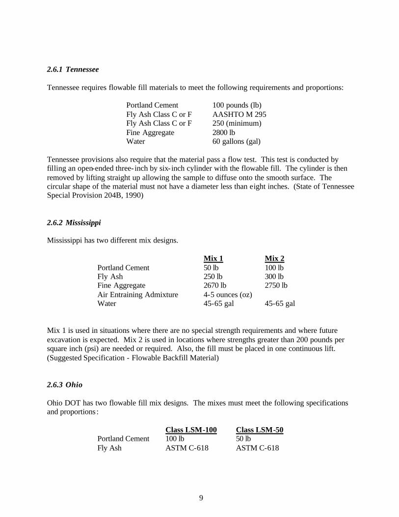
2.6.1 Tennessee Tennessee requires flowable fill materials to meet the following requirements and proportions:
Portland Cement 100 pounds (lb) Fly Ash Class C or F AASHTO M 295 Fly Ash Class C or F 250 (minimum) Fine Aggregate 2800 lb Water 60 gallons (gal)
Tennessee provisions also require that the material pass a flow test. This test is conducted by filling an open-ended three- inch by six- inch cylinder with the flowable fill. The cylinder is then removed by lifting straight up allowing the sample to diffuse onto the smooth surface. The circular shape of the material must not have a diameter less than eight inches. (State of Tennessee Special Provision 204B, 1990) 2.6.2 Mississippi Mississippi has two different mix designs.
Mix 1 Mix 2 Portland Cement 50 lb 100 lb Fly Ash 250 lb 300 lb Fine Aggregate 2670 lb 2750 lb Air Entraining Admixture 4-5 ounces (oz) Water 45-65 gal 45-65 gal
Mix 1 is used in situations where there are no special strength requirements and where future excavation is expected. Mix 2 is used in locations where strengths greater than 200 pounds per square inch (psi) are needed or required. Also, the fill must be placed in one continuous lift. (Suggested Specification - Flowable Backfill Material) 2.6.3 Ohio Ohio DOT has two flowable fill mix designs. The mixes must meet the following specifications and proportions :
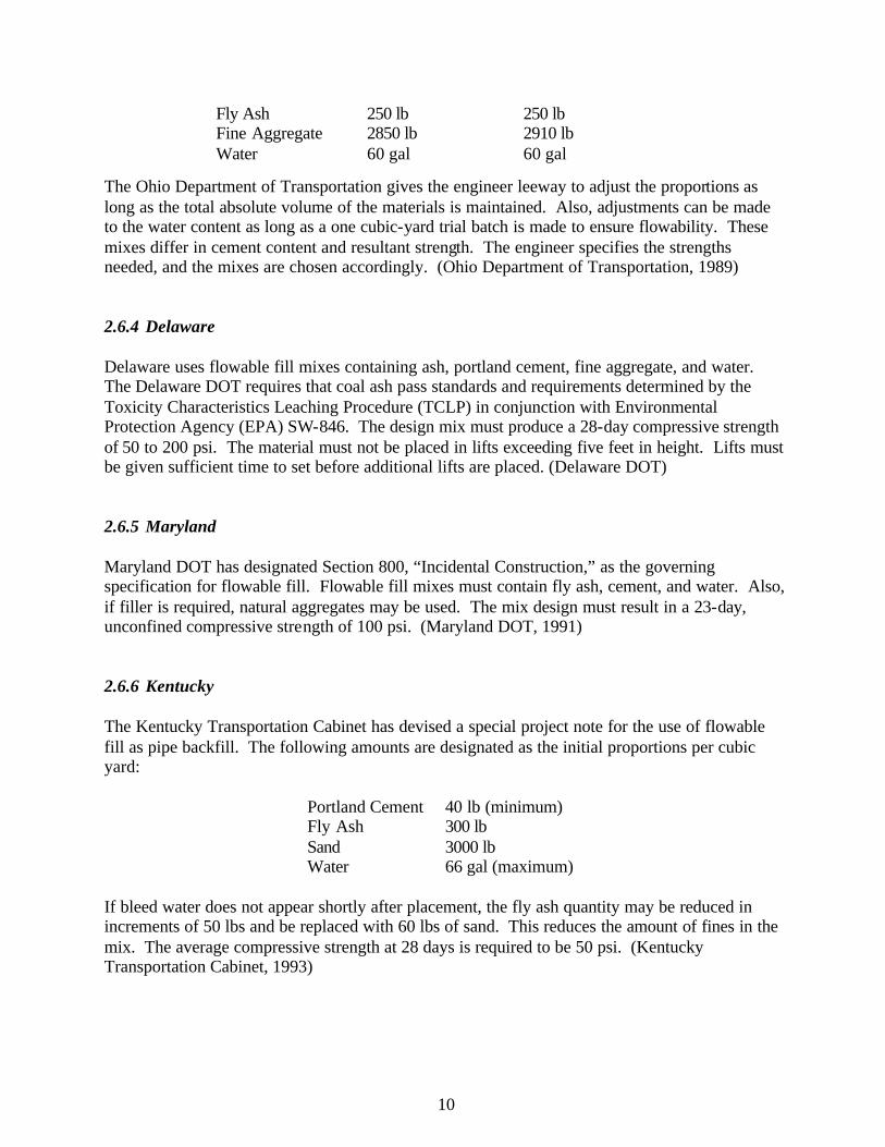
Class LSM-100 Class LSM-50 Portland Cement 100 lb 50 lb Fly Ash ASTM C-618 ASTM C-618
10
Fly Ash 250 lb 250 lb Fine Aggregate 2850 lb 2910 lb Water 60 gal 60 gal
The Ohio Department of Transportation gives the engineer leeway to adjust the proportions as long as the total absolute volume of the materials is maintained. Also, adjustments can be made to the water content as long as a one cubic-yard trial batch is made to ensure flowability. These mixes differ in cement content and resultant strength. The engineer specifies the strengths needed, and the mixes are chosen accordingly. (Ohio Department of Transportation, 1989) 2.6.4 Delaware Delaware uses flowable fill mixes containing ash, portland cement, fine aggregate, and water. The Delaware DOT requires that coal ash pass standards and requirements determined by the Toxicity Characteristics Leaching Procedure (TCLP) in conjunction with Environmental Protection Agency (EPA) SW-846. The design mix must produce a 28-day compressive strength of 50 to 200 psi. The material must not be placed in lifts exceeding five feet in height. Lifts must be given sufficient time to set before additional lifts are placed. (Delaware DOT) 2.6.5 Maryland Maryland DOT has designated Section 800, “Incidental Construction,” as the governing specification for flowable fill. Flowable fill mixes must contain fly ash, cement, and water. Also, if filler is required, natural aggregates may be used. The mix design must result in a 23-day, unconfined compressive strength of 100 psi. (Maryland DOT, 1991) 2.6.6 Kentucky The Kentucky Transportation Cabinet has devised a special project note for the use of flowable fill as pipe backfill. The following amounts are designated as the initial proportions per cubic yard:
Portland Cement 40 lb (minimum) Fly Ash 300 lb Sand 3000 lb Water 66 gal (maximum)
If bleed water does not appear shortly after placement, the fly ash quantity may be reduced in increments of 50 lbs and be replaced with 60 lbs of sand. This reduces the amount of fines in the mix. The average compressive strength at 28 days is required to be 50 psi. (Kentucky Transportation Cabinet, 1993)
11
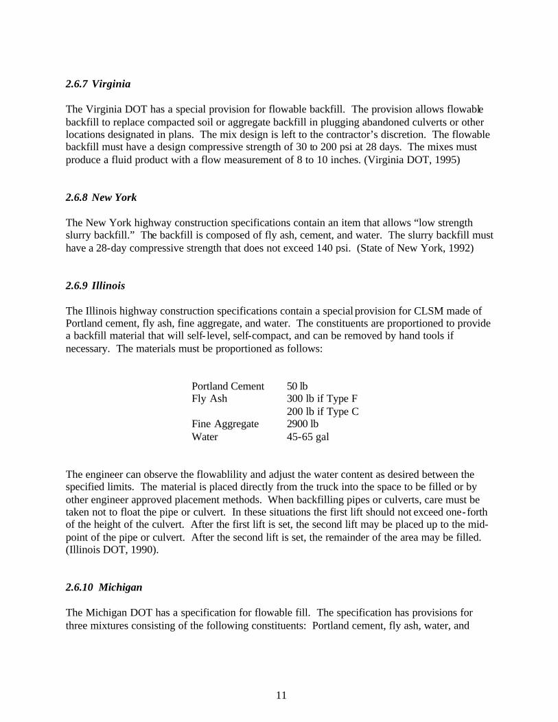
2.6.7 Virginia The Virginia DOT has a special provision for flowable backfill. The provision allows flowable backfill to replace compacted soil or aggregate backfill in plugging abandoned culverts or other locations designated in plans. The mix design is left to the contractor’s discretion. The flowable backfill must have a design compressive strength of 30 to 200 psi at 28 days. The mixes must produce a fluid product with a flow measurement of 8 to 10 inches. (Virginia DOT, 1995) 2.6.8 New York The New York highway construction specifications contain an item that allows “low strength slurry backfill.” The backfill is composed of fly ash, cement, and water. The slurry backfill must have a 28-day compressive strength that does not exceed 140 psi. (State of New York, 1992) 2.6.9 Illinois The Illinois highway construction specifications contain a special provision for CLSM made of Portland cement, fly ash, fine aggregate, and water. The constituents are proportioned to provide a backfill material that will self- level, self-compact, and can be removed by hand tools if necessary. The materials must be proportioned as follows:
Portland Cement 50 lb 300 lb if Type F Fly Ash 200 lb if Type C
Fine Aggregate 2900 lb Water 45-65 gal
The engineer can observe the flowablility and adjust the water content as desired between the specified limits. The material is placed directly from the truck into the space to be filled or by other engineer approved placement methods. When backfilling pipes or culverts, care must be taken not to float the pipe or culvert. In these situations the first lift should not exceed one-forth of the height of the culvert. After the first lift is set, the second lift may be placed up to the mid-point of the pipe or culvert. After the second lift is set, the remainder of the area may be filled. (Illinois DOT, 1990). 2.6.10 Michigan The Michigan DOT has a specification for flowable fill. The specification has provisions for three mixtures consisting of the following constituents: Portland cement, fly ash, water, and
12
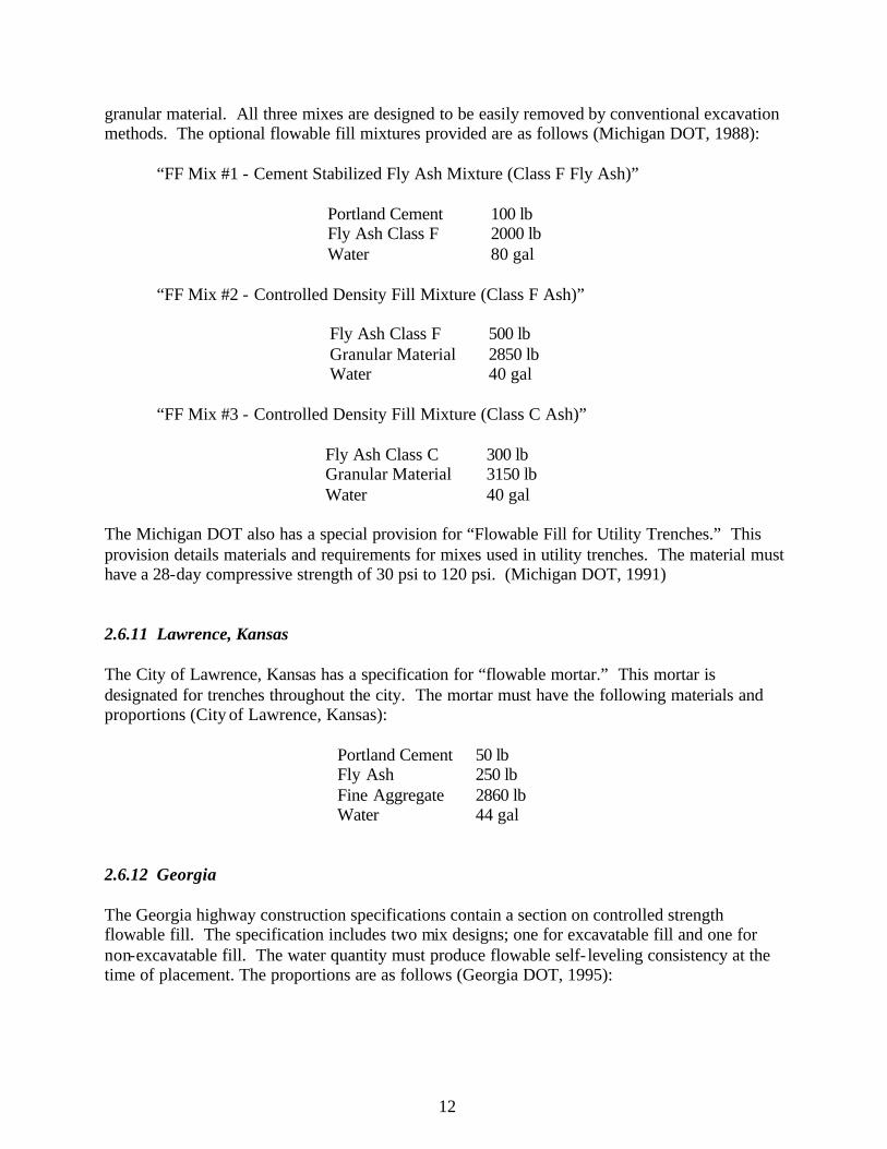
granular material. All three mixes are designed to be easily removed by conventional excavation methods. The optional flowable fill mixtures provided are as follows (Michigan DOT, 1988): “FF Mix #1 - Cement Stabilized Fly Ash Mixture (Class F Fly Ash)”
Portland Cement 100 lb Fly Ash Class F 2000 lb Water 80 gal
“FF Mix #2 - Controlled Density Fill Mixture (Class F Ash)”
Fly Ash Class F 500 lb Granular Material 2850 lb Water 40 gal
“FF Mix #3 - Controlled Density Fill Mixture (Class C Ash)”
Fly Ash Class C 300 lb Granular Material 3150 lb Water 40 gal
The Michigan DOT also has a special provision for “Flowable Fill for Utility Trenches.” This provision details materials and requirements for mixes used in utility trenches. The material must have a 28-day compressive strength of 30 psi to 120 psi. (Michigan DOT, 1991) 2.6.11 Lawrence, Kansas The City of Lawrence, Kansas has a specification for “flowable mortar.” This mortar is designated for trenches throughout the city. The mortar must have the following materials and proportions (City of Lawrence, Kansas):
Portland Cement 50 lb Fly Ash 250 lb Fine Aggregate 2860 lb Water 44 gal
2.6.12 Georgia The Georgia highway construction specifications contain a section on controlled strength flowable fill. The specification includes two mix designs; one for excavatable fill and one for non-excavatable fill. The water quantity must produce flowable self- leveling consistency at the time of placement. The proportions are as follows (Georgia DOT, 1995):
13
Excavatable Non-Excavatable Portland Cement Type 1 75-100 lb 75-100 lb Fly Ash 150-600 lb Air 15-35% 5-15% 28 Day Compressive Strength Maximum 100 psi Minimum 125 psi
2.6.13 Colorado Colorado highway construction specifications contain a section for flowable backfill as a replacement for typical structural backfills. The maximum desired strength is 60 psi and compaction is not required during construction. The proportions are as follows (Colorado DOH):
Portland Cement 42 lb Sand (ASTM C-33) 1845 lb Coarse Aggregate 1700 lb Water 39 gal
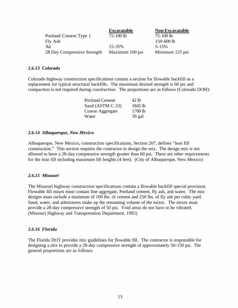
2.6.14 Albuquerque, New Mexico Albuquerque, New Mexico, construction specifications, Section 207, defines “lean fill construction.” This section requires the contractor to design the mix. The design mix is not allowed to have a 28-day compressive strength greater than 60 psi. There are other requirements for the lean fill including maximum lift heights (4 feet). (City of Albuquerque, New Mexico) 2.6.15 Missouri The Missouri highway construction specifications contain a flowable backfill special provision. Flowable fill mixes must contain fine aggregate, Portland cement, fly ash, and water. The mix designs must include a minimum of 100 lbs. of cement and 250 lbs. of fly ash per cubic yard. Sand, water, and admixtures make up the remaining volume of the mixes. The mixes must provide a 28-day compressive strength of 50 psi. Void areas do not have to be vibrated. (Missouri Highway and Transportation Department, 1992) 2.6.16 Florida The Florida DOT provides mix guidelines for flowable fill. The contractor is responsible for designing a mix to provide a 28-day compressive strength of approximately 50-150 psi. The general proportions are as follows:
14
Cement 50-100 lb Fly Ash or Slag 0-600 lb Fine Sand Adjust to yield one cubic yard Water 60 gal (maximum)
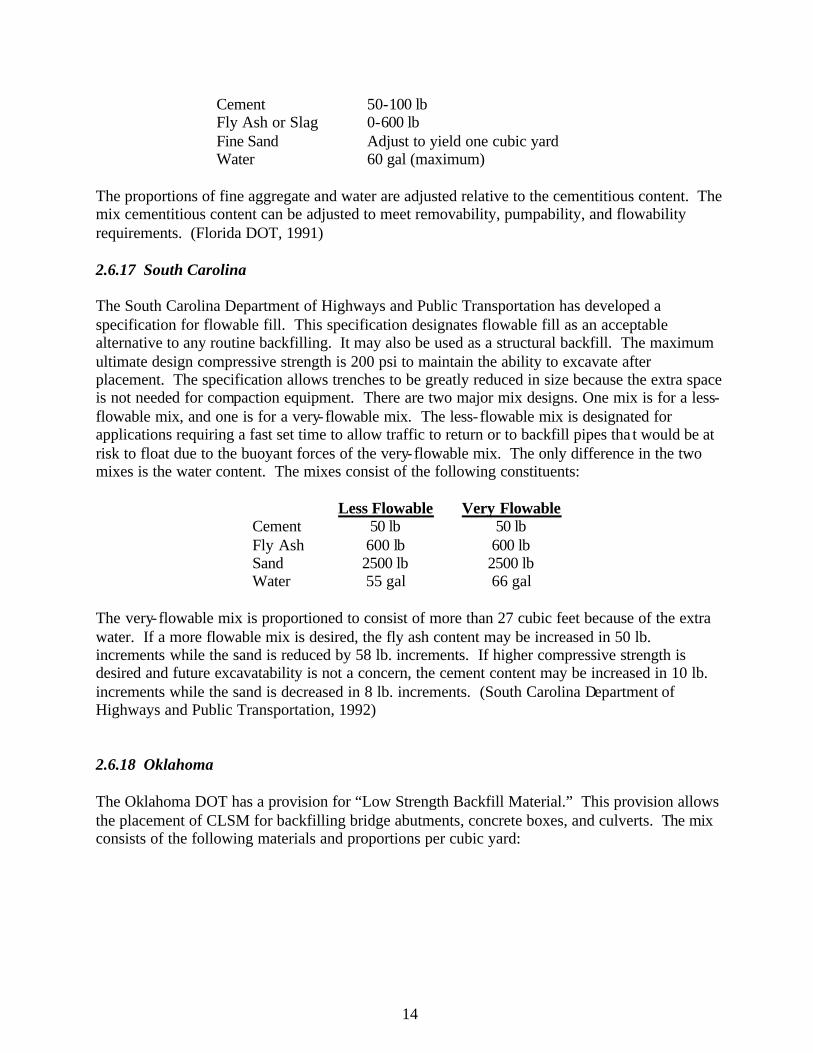
The proportions of fine aggregate and water are adjusted relative to the cementitious content. The mix cementitious content can be adjusted to meet removability, pumpability, and flowability requirements. (Florida DOT, 1991) 2.6.17 South Carolina The South Carolina Department of Highways and Public Transportation has developed a specification for flowable fill. This specification designates flowable fill as an acceptable alternative to any routine backfilling. It may also be used as a structural backfill. The maximum ultimate design compressive strength is 200 psi to maintain the ability to excavate after placement. The specification allows trenches to be greatly reduced in size because the extra space is not needed for compaction equipment. There are two major mix designs. One mix is for a less-flowable mix, and one is for a very-flowable mix. The less- flowable mix is designated for applications requiring a fast set time to allow traffic to return or to backfill pipes tha t would be at risk to float due to the buoyant forces of the very-flowable mix. The only difference in the two mixes is the water content. The mixes consist of the following constituents:
Less Flowable Very Flowable Cement 50 lb 50 lb Fly Ash 600 lb 600 lb Sand 2500 lb 2500 lb Water 55 gal 66 gal
The very-flowable mix is proportioned to consist of more than 27 cubic feet because of the extra water. If a more flowable mix is desired, the fly ash content may be increased in 50 lb. increments while the sand is reduced by 58 lb. increments. If higher compressive strength is desired and future excavatability is not a concern, the cement content may be increased in 10 lb. increments while the sand is decreased in 8 lb. increments. (South Carolina Department of Highways and Public Transportation, 1992) 2.6.18 Oklahoma The Oklahoma DOT has a provision for “Low Strength Backfill Material.” This provision allows the placement of CLSM for backfilling bridge abutments, concrete boxes, and culverts. The mix consists of the following materials and proportions per cubic yard:
15
Cement 50 lb Fly Ash ASTM C-618 Fly Ash 250 lb Sand 2910 lb Water 60 gal
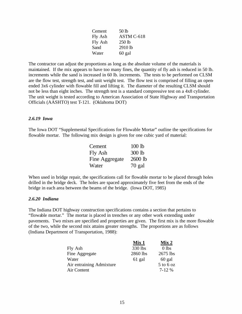
The contractor can adjust the proportions as long as the absolute volume of the materials is maintained. If the mix appears to have too many fines, the quantity of fly ash is reduced in 50 lb. increments while the sand is increased in 60 lb. increments. The tests to be performed on CLSM are the flow test, strength test, and unit weight test. The flow test is comprised of filling an open-ended 3x6 cylinder with flowable fill and lifting it. The diameter of the resulting CLSM should not be less than eight inches. The strength test is a standard compressive test on a 4x8 cylinder. The unit weight is tested according to American Association of State Highway and Transportation Officials (AASHTO) test T-121. (Oklahoma DOT) 2.6.19 Iowa The Iowa DOT “Supplemental Specifications for Flowable Mortar” outline the specifications for flowable mortar. The following mix design is given for one cubic yard of material:
Cement 100 lb Fly Ash 300 lb Fine Aggregate 2600 lb Water 70 gal
When used in bridge repair, the specifications call for flowable mortar to be placed through holes drilled in the bridge deck. The holes are spaced approximately five feet from the ends of the bridge in each area between the beams of the bridge. (Iowa DOT, 1985) 2.6.20 Indiana The Indiana DOT highway construction specifications contains a section that pertains to “flowable mortar.” The mortar is placed in trenches or any other work extending under pavements. Two mixes are specified and properties are given. The first mix is the more flowable of the two, while the second mix attains greater strengths. The proportions are as follows (Indiana Department of Transportation, 1988):
Mix 1 Mix 2 Fly Ash 330 lbs 0 lbs Fine Aggregate 2860 lbs 2675 lbs Water 61 gal 60 gal Air entraining Admixture 5 to 6 oz Air Content 7-12 %
16
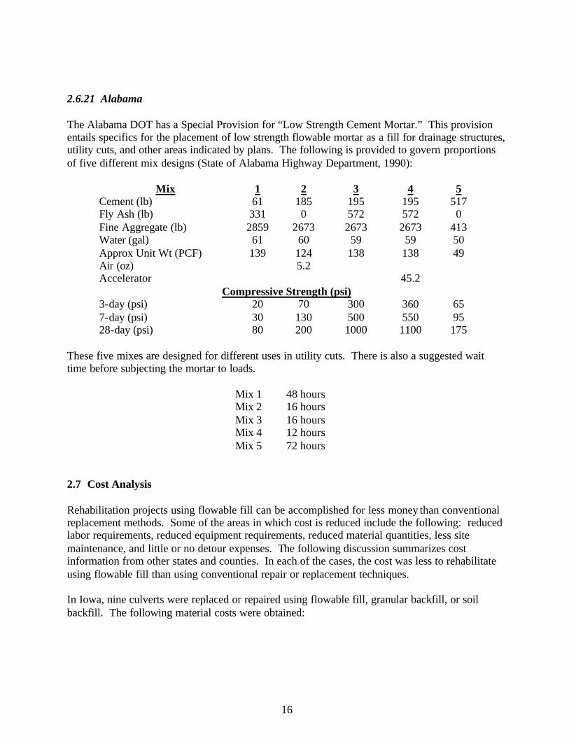
2.6.21 Alabama The Alabama DOT has a Special Provision for “Low Strength Cement Mortar.” This provision entails specifics for the placement of low strength flowable mortar as a fill for drainage structures, utility cuts, and other areas indicated by plans. The following is provided to govern proportions of five different mix designs (State of Alabama Highway Department, 1990):
Mix 1 2 3 4 5 Cement (lb) 61 185 195 195 517 Fly Ash (lb) 331 0 572 572 0 Fine Aggregate (lb) 2859 2673 2673 2673 413 Water (gal) 61 60 59 59 50 Approx Unit Wt (PCF) 139 124 138 138 49 Air (oz) 5.2 Accelerator 45.2
Compressive Strength (psi) 3-day (psi) 20 70 300 360 65 7-day (psi) 30 130 500 550 95 28-day (psi) 80 200 1000 1100 175
These five mixes are designed for different uses in utility cuts. There is also a suggested wait time before subjecting the mortar to loads.
Mix 1 48 hours Mix 2 16 hours Mix 3 16 hours Mix 4 12 hours Mix 5 72 hours
2.7 Cost Analysis Rehabilitation projects using flowable fill can be accomplished for less money than conventional replacement methods. Some of the areas in which cost is reduced include the following: reduced labor requirements, reduced equipment requirements, reduced material quantities, less site maintenance, and little or no detour expenses. The following discussion summarizes cost information from other states and counties. In each of the cases, the cost was less to rehabilitate using flowable fill than using conventional repair or replacement techniques. In Iowa, nine culverts were replaced or repaired using flowable fill, granular backfill, or soil backfill. The following material costs were obtained:
17
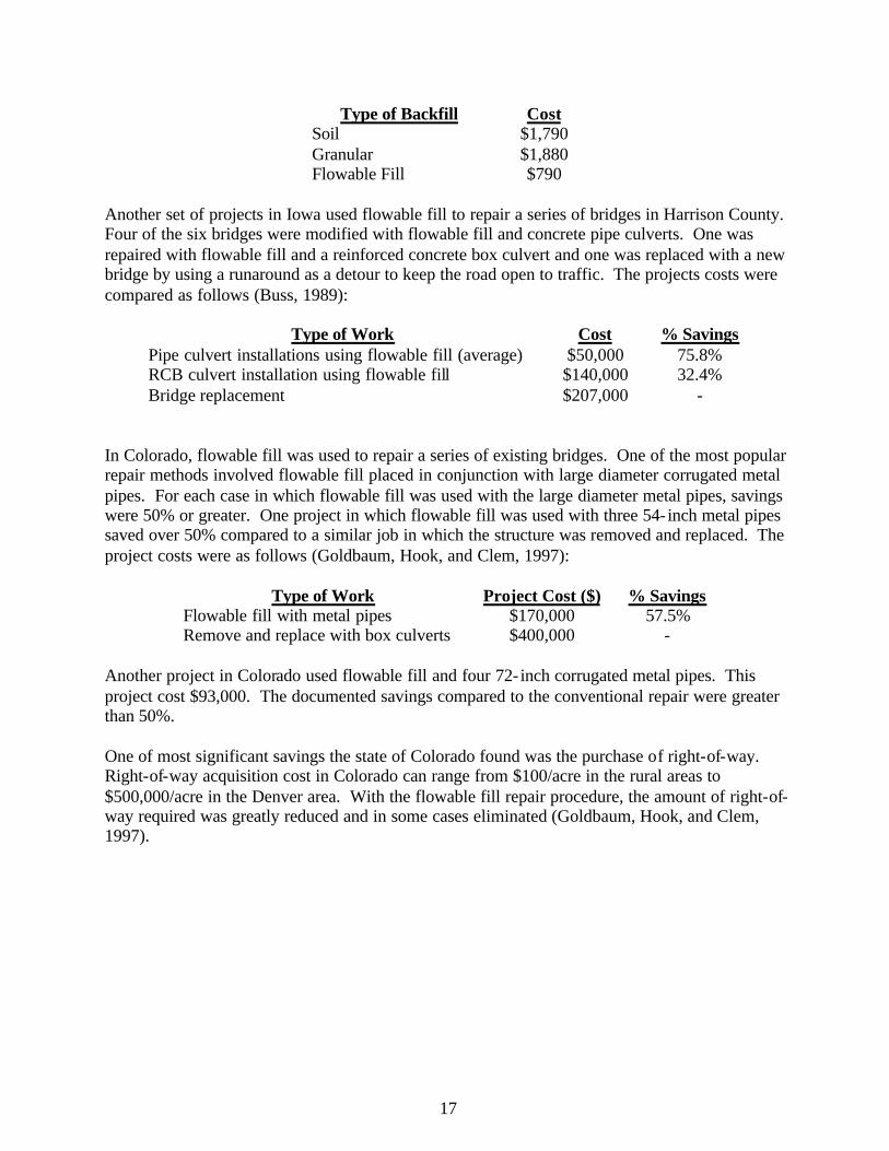
Type of Backfill Cost Soil $1,790 Granular $1,880 Flowable Fill $790
Another set of projects in Iowa used flowable fill to repair a series of bridges in Harrison County. Four of the six bridges were modified with flowable fill and concrete pipe culverts. One was repaired with flowable fill and a reinforced concrete box culvert and one was replaced with a new bridge by using a runaround as a detour to keep the road open to traffic. The projects costs were compared as follows (Buss, 1989):
Type of Work Cost % Savings Pipe culvert installations using flowable fill (average) $50,000 75.8% RCB culvert installation using flowable fill $140,000 32.4% Bridge replacement $207,000 -
In Colorado, flowable fill was used to repair a series of existing bridges. One of the most popular repair methods involved flowable fill placed in conjunction with large diameter corrugated metal pipes. For each case in which flowable fill was used with the large diameter metal pipes, savings were 50% or greater. One project in which flowable fill was used with three 54- inch metal pipes saved over 50% compared to a similar job in which the structure was removed and replaced. The project costs were as follows (Goldbaum, Hook, and Clem, 1997):
Type of Work Project Cost ($) % Savings Flowable fill with metal pipes $170,000 57.5% Remove and replace with box culverts $400,000 -
Another project in Colorado used flowable fill and four 72- inch corrugated metal pipes. This project cost $93,000. The documented savings compared to the conventional repair were greater than 50%. One of most significant savings the state of Colorado found was the purchase of right-of-way. Right-of-way acquisition cost in Colorado can range from $100/acre in the rural areas to $500,000/acre in the Denver area. With the flowable fill repair procedure, the amount of right-of-way required was greatly reduced and in some cases eliminated (Goldbaum, Hook, and Clem, 1997).
18
3.0 The Wadley, Alabama Field Demonstration
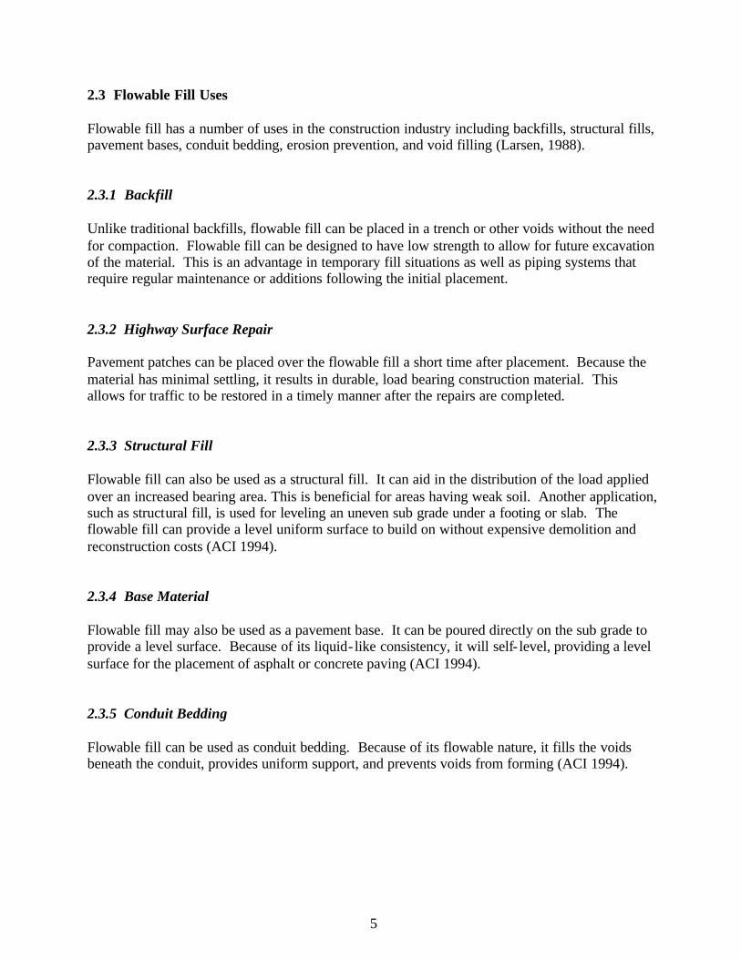
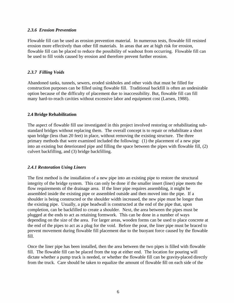
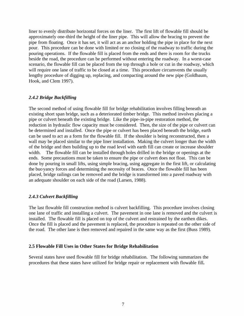
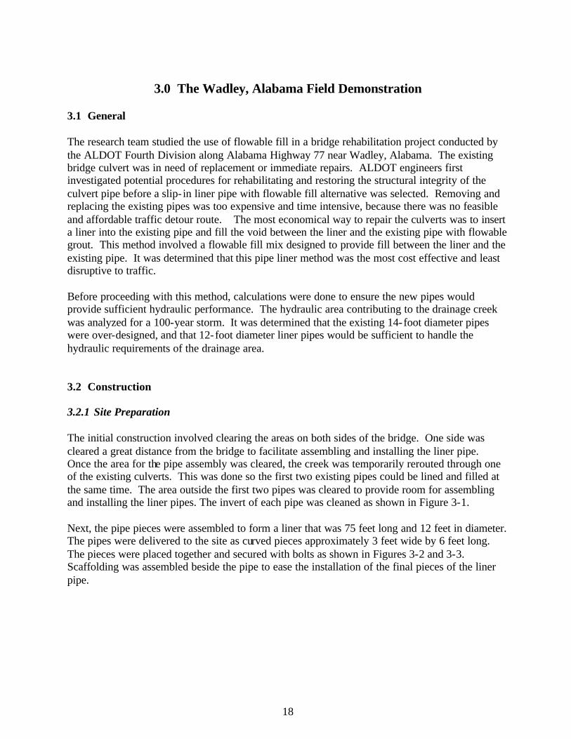
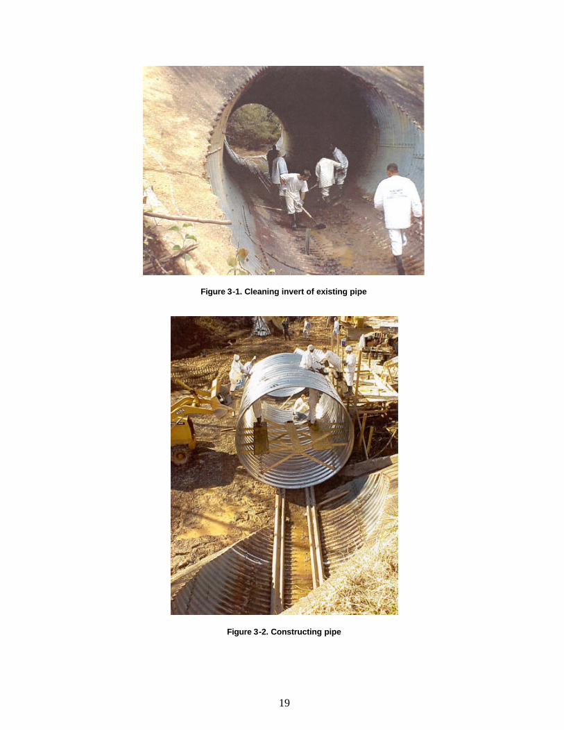
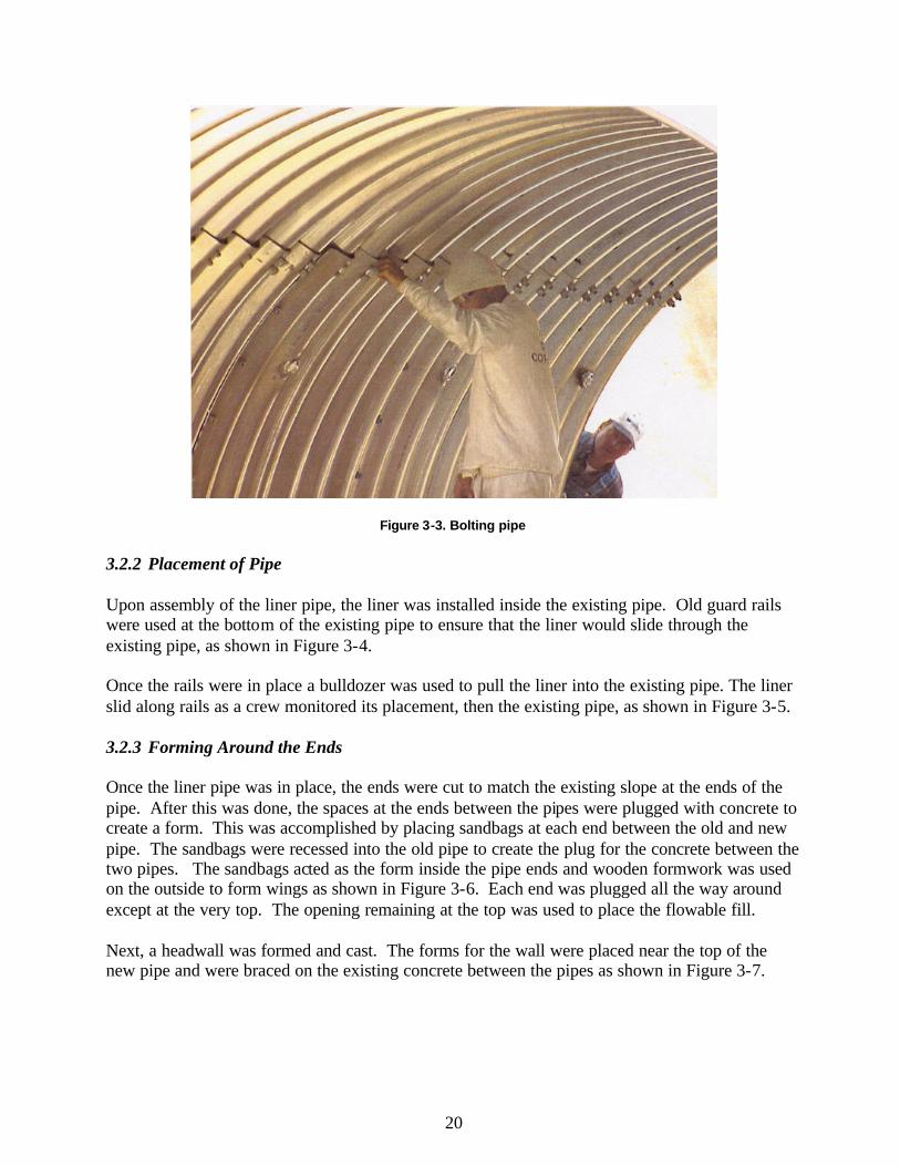
3.1 General The research team studied the use of flowable fill in a bridge rehabilitation project conducted by the ALDOT Fourth Division along Alabama Highway 77 near Wadley, Alabama. The existing bridge culvert was in need of replacement or immediate repairs. ALDOT engineers first investigated potential procedures for rehabilitating and restoring the structural integrity of the culvert pipe before a slip- in liner pipe with flowable fill alternative was selected. Removing and replacing the existing pipes was too expensive and time intensive, because there was no feasible and affordable traffic detour route. The most economical way to repair the culverts was to insert a liner into the existing pipe and fill the void between the liner and the existing pipe with flowable grout. This method involved a flowable fill mix designed to provide fill between the liner and the existing pipe. It was determined that this pipe liner method was the most cost effective and least disruptive to traffic. Before proceeding with this method, calculations were done to ensure the new pipes would provide sufficient hydraulic performance. The hydraulic area contributing to the drainage creek was analyzed for a 100-year storm. It was determined that the existing 14-foot diameter pipes were over-designed, and that 12-foot diameter liner pipes would be sufficient to handle the hydraulic requirements of the drainage area. 3.2 Construction 3.2.1 Site Preparation The initial construction involved clearing the areas on both sides of the bridge. One side was cleared a great distance from the bridge to facilitate assembling and installing the liner pipe. Once the area for the pipe assembly was cleared, the creek was temporarily rerouted through one of the existing culverts. This was done so the first two existing pipes could be lined and filled at the same time. The area outside the first two pipes was cleared to provide room for assembling and installing the liner pipes. The invert of each pipe was cleaned as shown in Figure 3-1. Next, the pipe pieces were assembled to form a liner that was 75 feet long and 12 feet in diameter. The pipes were delivered to the site as curved pieces approximately 3 feet wide by 6 feet long. The pieces were placed together and secured with bolts as shown in Figures 3-2 and 3-3. Scaffolding was assembled beside the pipe to ease the installation of the final pieces of the liner pipe.
19
Figure 3-1. Cleaning invert of existing pipe
Figure 3-2. Constructing pipe
20
Figure 3-3. Bolting pipe
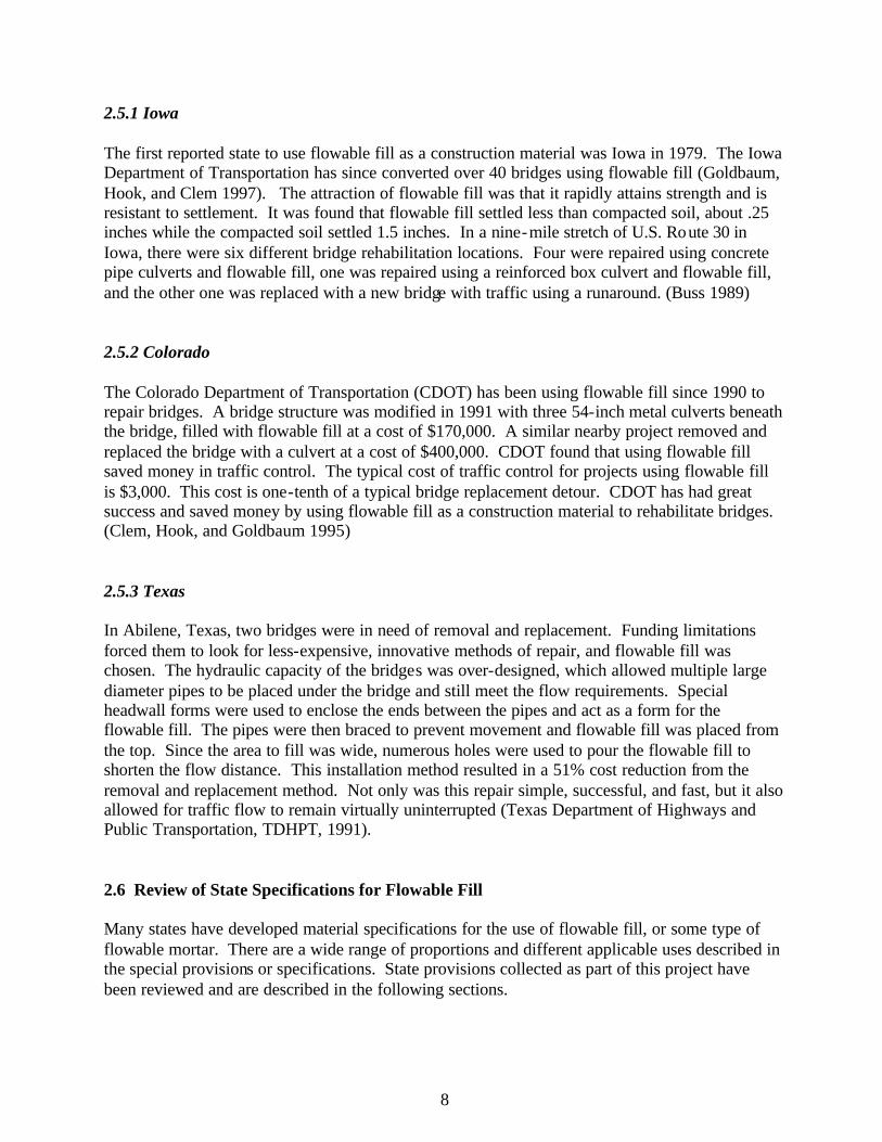
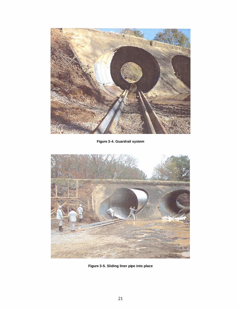
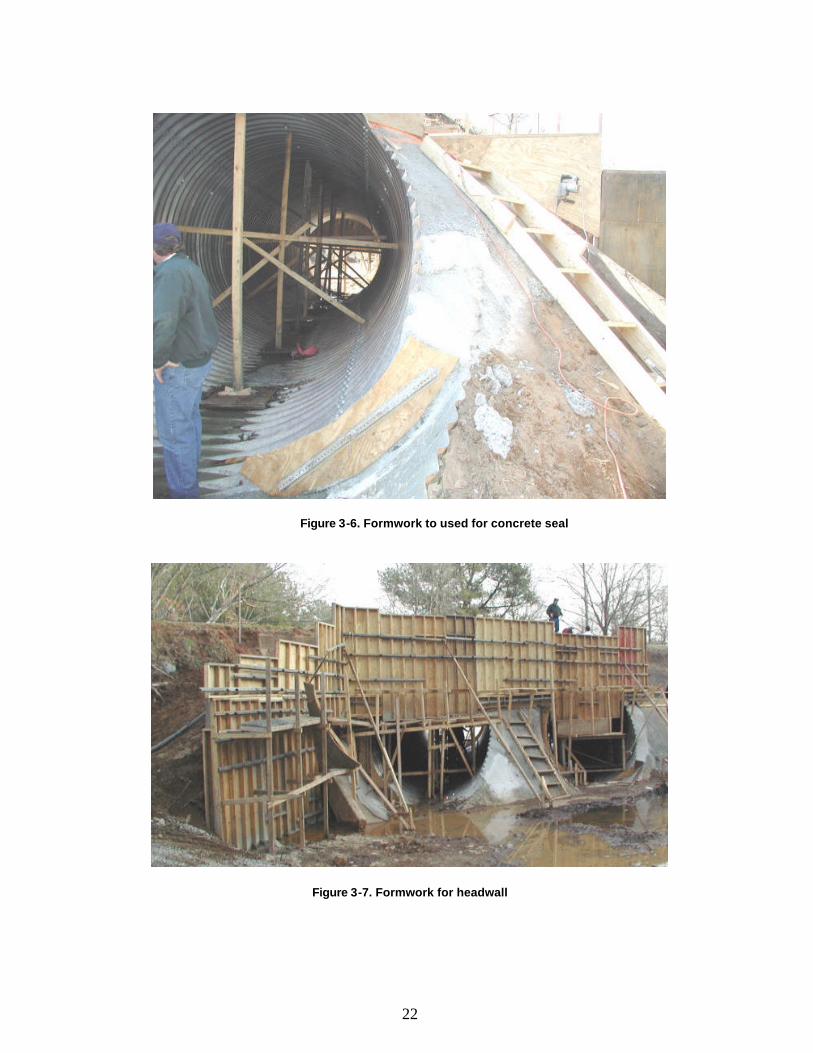
3.2.2 Placement of Pipe Upon assembly of the liner pipe, the liner was installed inside the existing pipe. Old guard rails were used at the bottom of the existing pipe to ensure that the liner would slide through the existing pipe, as shown in Figure 3-4. Once the rails were in place a bulldozer was used to pull the liner into the existing pipe. The liner slid along rails as a crew monitored its placement, then the existing pipe, as shown in Figure 3-5. 3.2.3 Forming Around the Ends Once the liner pipe was in place, the ends were cut to match the existing slope at the ends of the pipe. After this was done, the spaces at the ends between the pipes were plugged with concrete to create a form. This was accomplished by placing sandbags at each end between the old and new pipe. The sandbags were recessed into the old pipe to create the plug for the concrete between the two pipes. The sandbags acted as the form inside the pipe ends and wooden formwork was used on the outside to form wings as shown in Figure 3-6. Each end was plugged all the way around except at the very top. The opening remaining at the top was used to place the flowable fill. Next, a headwall was formed and cast. The forms for the wall were placed near the top of the new pipe and were braced on the existing concrete between the pipes as shown in Figure 3-7.
21
Figure 3-4. Guardrail system
Figure 3-5. Sliding liner pipe into place
22
Figure 3-6. Formwork to used for concrete seal
Figure 3-7. Formwork for headwall
23
3.2.4 Bracing Installation The liner pipe was braced in several ways. Wood braces were placed against the liner pipe at 60-degree intervals. There were additional braces in the vertical direction. These braces are usually the most important because they restrain the pipe from floating. Buoyancy forces must be calculated before placing flowable fill to determine the amount of vertical bracing necessary. Signposts were used as vertical braces. The braces were assembled, placed in the 3- inch holes at the top of the liner, and jacked into place to keep the liner from moving. The signposts used for bracing extended through the top of the liner and pressed against the top of the existing pipe. A piece of lumber was placed at the bottom of each brace to distribute the load and prevent punching through the liner.
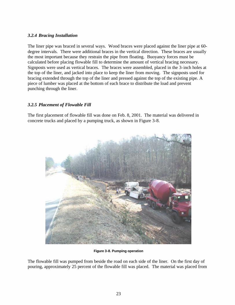
3.2.5 Placement of Flowable Fill The first placement of flowable fill was done on Feb. 8, 2001. The material was delivered in concrete trucks and placed by a pumping truck, as shown in Figure 3-8.
Figure 3-8. Pumping operation The flowable fill was pumped from beside the road on each side of the liner. On the first day of pouring, approximately 25 percent of the flowable fill was placed. The material was placed from
24
the top center of the uphill side of the liner. The second lift filled the void to approximately 80 percent. The last lift was poured from the same location and filled the remaining 20 percent. The flowable fill was placed evenly on both sides of the pipe to ensure equal depth lifts and prevent movement of the liner pipe. 3.2.6 Third Pipe Installation Once the first two pipes were lined and the flowable fill was completely in place, the creek was rerouted through the two lined pipes so work could continue on the third pipe. Due to space limitations, the third liner pipe was assembled on the downstream side of the bridge, and was pulled into place with a chain and backhoe, similar to the first two. The construction process used for the first two pipes was followed once the liner pipe was in place.
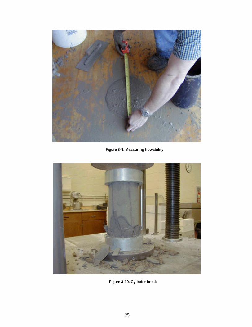
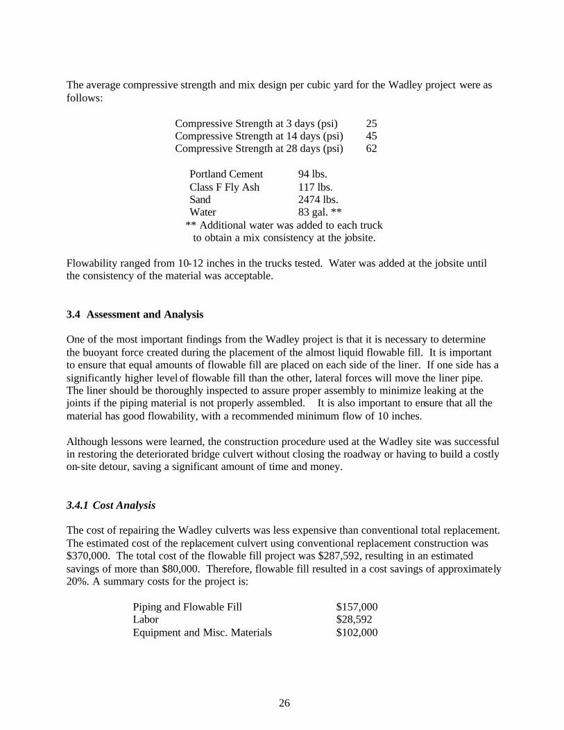
3.3 Material Test Results Properties of flowable fill used for projects in other states include compressive strength and flowability. Flowability is tested at the construction site while compressive strength is tested in the laboratory. Testing the flowability of the mixes was performed in accordance with ASTM PS 28-95. The flowability was measured at multiple time intervals within the mixing process until the desired flow was achieved. The flow test procedure involved filling a 3”x6” open-ended cylinder with the material. The cylinder was then raised causing the material to flow outward from the bottom of the cylinder. The diameter of the flow was measured along two perpendicular directions (Figure 3-9), and the average was recorded as the flowability. ACI suggests that, for a good flow, the diameter of the spread should be at least 8 inches. The required minimum flow value insures the proper placement in congested settings and that the self- leveling characteristics of the mix are maintained. Strength is an important engineering parameter in CLSMs, since excavation of portions of the backfill with construction machinery may be required during the project or after its completion. Strength is typically measured by means of unconfined compression tests on cylindrical samples having a length-to-diameter ratio of 2:1. Cylinders were cast in accordance with ASTM D 4832 for compressive strength testing. These specimens were tested at the ages of 3, 7, and 28 days. Three days after mixing, the plastic molds were stripped from the cylinders, and the first set of three cylinders was tested (Figure 3-10). Due to the material’s low strength and susceptibility to damage during the stripping process, the molds were pre-split using a razor set at the exact thickness of the plastic cylinder mold. The average strength of the three cylinders was calculated for each test age. The loading rate conformed to ASTM D 4832.
25
Figure 3-9. Measuring flowability
Figure 3-10. Cylinder break
26
The average compressive strength and mix design per cubic yard for the Wadley project were as follows:
Compressive Strength at 3 days (psi) 25 Compressive Strength at 14 days (psi) 45 Compressive Strength at 28 days (psi) 62
Portland Cement 94 lbs. Class F Fly Ash 117 lbs. Sand 2474 lbs. Water 83 gal. **
** Additional water was added to each truck to obtain a mix consistency at the jobsite.
Flowability ranged from 10-12 inches in the trucks tested. Water was added at the jobsite until the consistency of the material was acceptable. 3.4 Assessment and Analysis One of the most important findings from the Wadley project is that it is necessary to determine the buoyant force created during the placement of the almost liquid flowable fill. It is important to ensure that equal amounts of flowable fill are placed on each side of the liner. If one side has a significantly higher level of flowable fill than the other, lateral forces will move the liner pipe. The liner should be thoroughly inspected to assure proper assembly to minimize leaking at the joints if the piping material is not properly assembled. It is also important to ensure that all the material has good flowability, with a recommended minimum flow of 10 inches. Although lessons were learned, the construction procedure used at the Wadley site was successful in restoring the deteriorated bridge culvert without closing the roadway or having to build a costly on-site detour, saving a significant amount of time and money. 3.4.1 Cost Analysis The cost of repairing the Wadley culverts was less expensive than conventional total replacement. The estimated cost of the replacement culvert using conventional replacement construction was $370,000. The total cost of the flowable fill project was $287,592, resulting in an estimated savings of more than $80,000. Therefore, flowable fill resulted in a cost savings of approximately 20%. A summary costs for the project is:
Piping and Flowable Fill $157,000 Labor $28,592 Equipment and Misc. Materials $102,000
27
3.4.2 Owner Input At the conclusion of the Wadley project, ALDOT’s Fourth Division project engineer was interviewed and provided ideas on ways to save time, money, and material. The first, and possibly one of the biggest time savings would come from ordering the liner pipe partially assembled with the ends pre-cut to match the desired finished slope. This means the liner would arrive at the site with the proper angle already cut at each end, so it would match the slope of the existing pipe. A large amount of time was spent assembling and cutting the Wadley liner. Another phase that could be improved was the forming of the ends between the two pipes. More efficient ways to make the forms were discussed. This could involve a combination of sandbags and wood forms, or the use of other materials such as prefabricated, reusable steel forms. An area that could be improved is the choice and configuration of the liner. Not only could it be ordered pre-cut, but also the plug locations could be placed at only a few designated positions. This means that plugs would not be every few feet as in the Wadley project liners, but instead be placed at predetermined locations where bracing or observation of material flow is necessary. By reducing the number of plugs, the piping material cost from the manufacturer would be reduced. The last improvement mentioned for the project involved the labor force. Inmate labor was used on the Wadley project. This type of labor was not always consistent, and a workforce trained in this type of construction would be more efficient. Another issue that was discussed was the time of the project. Weather and scheduling difficulties caused discontinuities in the work, increasing the total time required for the project to be approximately six months. If this project were repeated, working continuously from start to finish, it would take approximately three months to complete. The three-month schedule would utilize three experienced workers with the occasional need for additional labor forces. For the next project of this type, time, material, and equipment cost could be reduced. It was estimated that a similar job could be completed for around $225,000 by applying the experience and knowledge that was gained from this project. This would achieve approximately 39% cost savings compared to conventional total replacement.
28
4. Shelby County Demonstration Projects 4.1 General Shelby County is the fastest growing county in Alabama and one of the fastest growing counties in the United States. This rapid growth requires aggressive roadway construction and bridge replacement by the county highway department. Posted bridges can limit development, because bridges on the access roadway were unable to sustain the applied load. To keep pace with development, local governments such as Shelby County must utilize the most cost-effective and efficient bridge replacement and repair techniques available. Therefore, Shelby County was willing and ready to participate in innovative bridge replacement research. Four structures in need of replacement were identified as candidates for the project. These structures included one corrugated metal pipe and three short span timber bridges. All of these structures met the criteria for use of flowable fill. The criteria included the ability to reduce the cross section area of the drainage structure based on the hydrology of the drainage area the structure served. The geometry of the opening had to permit a replacement structure, such as a circular or arch pipe, to be placed inside the existing structure. Each of the projects was carefully monitored during the construction process to determine the best construction techniques and flowable fill mix. All of the findings were documented and refined from one project to the next to decrease construction time, improve desired mix properties and improve final project quality. Laboratory and field tests were performed on the flowable fill material. Mix consistency was determined by taking flow measurements per ASTM PS 28-95. Cylinders were cast on-site and tested in the laboratory in accordance with ASTM D 4832 to determine compressive strength properties.
Construction costs associated with labor, equipment and materials were tracked on each project to compare construction using flowable fill to conventional replacement construction. Benefits other than direct construction cost savings were also identified. 4.2 Shelby County Project Replacing Metal Pipe Culvert The first Shelby County project was located on County Road 43 approximately eight miles north of US Highway 280. The structure in need of replacement was a deteriorated 84- inch diameter corrugated metal pipe under approximately 6 feet of cover. The average daily traffic volumes were high enough to warrant the construction of a very costly onsite detour. Site conditions alone made the construction of an onsite detour unfavorable due to right-of-way constraints, utility conflicts, and depths of fill over the pipe.
29
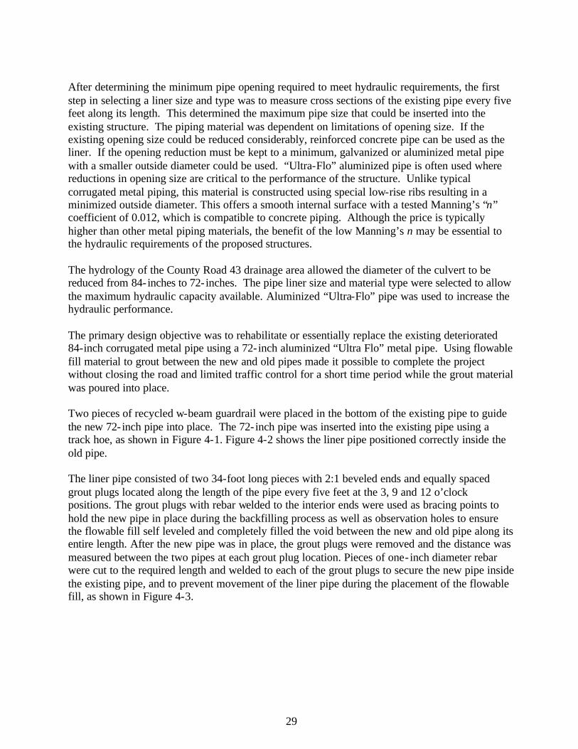
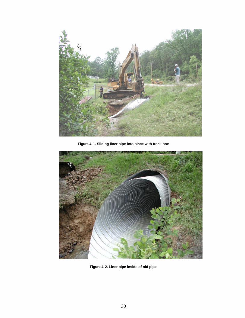
After determining the minimum pipe opening required to meet hydraulic requirements, the first step in selecting a liner size and type was to measure cross sections of the existing pipe every five feet along its length. This determined the maximum pipe size that could be inserted into the existing structure. The piping material was dependent on limitations of opening size. If the existing opening size could be reduced considerably, reinforced concrete pipe can be used as the liner. If the opening reduction must be kept to a minimum, galvanized or aluminized metal pipe with a smaller outside diameter could be used. “Ultra-Flo” aluminized pipe is often used where reductions in opening size are critical to the performance of the structure. Unlike typical corrugated metal piping, this material is constructed using special low-rise ribs resulting in a minimized outside diameter. This offers a smooth internal surface with a tested Manning’s “n” coefficient of 0.012, which is compatible to concrete piping. Although the price is typically higher than other metal piping materials, the benefit of the low Manning’s n may be essential to the hydraulic requirements of the proposed structures. The hydrology of the County Road 43 drainage area allowed the diameter of the culvert to be reduced from 84- inches to 72- inches. The pipe liner size and material type were selected to allow the maximum hydraulic capacity available. Aluminized “Ultra-Flo” pipe was used to increase the hydraulic performance. The primary design objective was to rehabilitate or essentially replace the existing deteriorated 84-inch corrugated metal pipe using a 72- inch aluminized “Ultra Flo” metal pipe. Using flowable fill material to grout between the new and old pipes made it possible to complete the project without closing the road and limited traffic control for a short time period while the grout material was poured into place. Two pieces of recycled w-beam guardrail were placed in the bottom of the existing pipe to guide the new 72- inch pipe into place. The 72- inch pipe was inserted into the existing pipe using a track hoe, as shown in Figure 4-1. Figure 4-2 shows the liner pipe positioned correctly inside the old pipe.
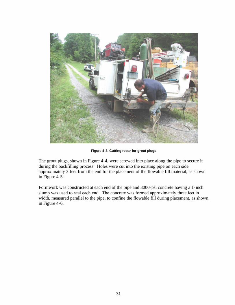
The liner pipe consisted of two 34-foot long pieces with 2:1 beveled ends and equally spaced grout plugs located along the length of the pipe every five feet at the 3, 9 and 12 o’clock positions. The grout plugs with rebar welded to the interior ends were used as bracing points to hold the new pipe in place during the backfilling process as well as observation holes to ensure the flowable fill self leveled and completely filled the void between the new and old pipe along its entire length. After the new pipe was in place, the grout plugs were removed and the distance was measured between the two pipes at each grout plug location. Pieces of one- inch diameter rebar were cut to the required length and welded to each of the grout plugs to secure the new pipe inside the existing pipe, and to prevent movement of the liner pipe during the placement of the flowable fill, as shown in Figure 4-3.
30
Figure 4-1. Sliding liner pipe into place with track hoe
Figure 4-2. Liner pipe inside of old pipe
31
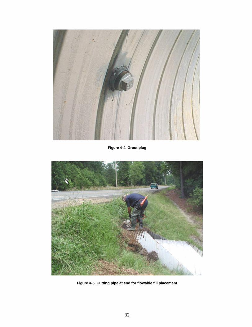
Figure 4-3. Cutting rebar for grout plugs The grout plugs, shown in Figure 4-4, were screwed into place along the pipe to secure it during the backfilling process. Holes were cut into the existing pipe on each side approximately 3 feet from the end for the placement of the flowable fill material, as shown in Figure 4-5. Formwork was constructed at each end of the pipe and 3000-psi concrete having a 1- inch slump was used to seal each end. The concrete was formed approximately three feet in width, measured parallel to the pipe, to confine the flowable fill during placement, as shown in Figure 4-6.
32
Figure 4-4. Grout plug
Figure 4-5. Cutting pipe at end for flowable fill placement
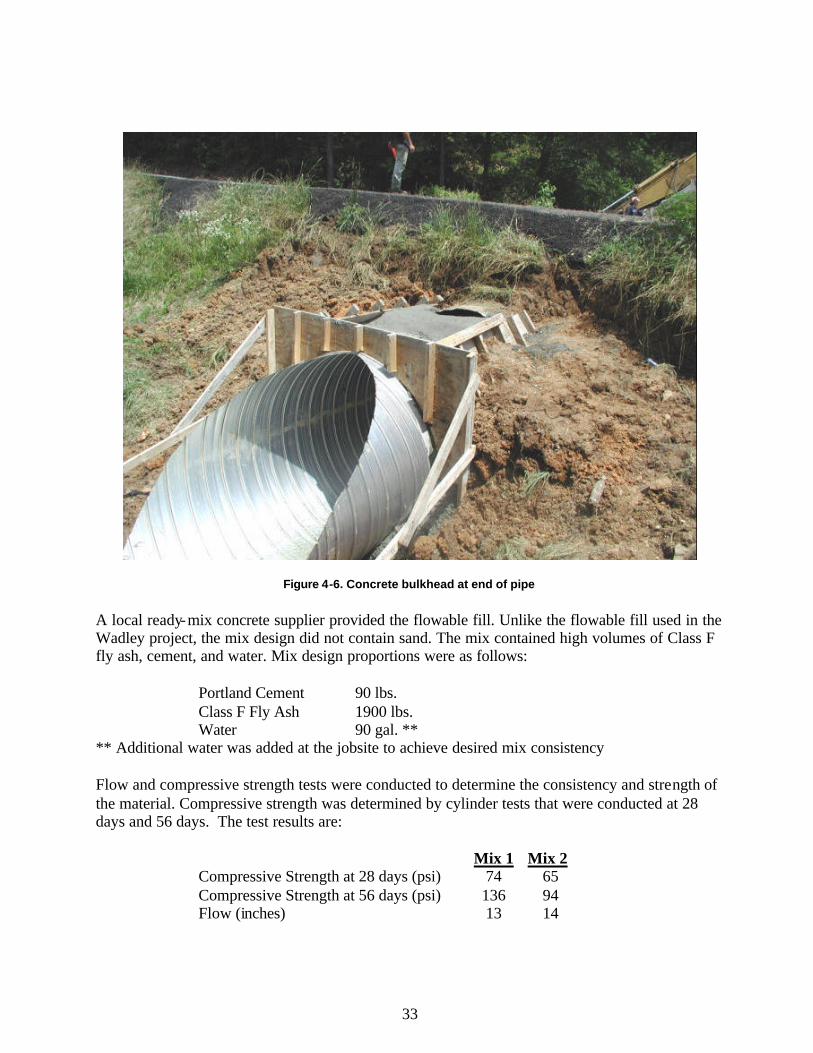
33
Figure 4-6. Concrete bulkhead at end of pipe A local ready-mix concrete supplier provided the flowable fill. Unlike the flowable fill used in the Wadley project, the mix design did not contain sand. The mix contained high volumes of Class F fly ash, cement, and water. Mix design proportions were as follows:
Portland Cement 90 lbs. Class F Fly Ash 1900 lbs. Water 90 gal. **
** Additional water was added at the jobsite to achieve desired mix consistency Flow and compressive strength tests were conducted to determine the consistency and strength of the material. Compressive strength was determined by cylinder tests that were conducted at 28 days and 56 days. The test results are:
Mix 1 Mix 2 Compressive Strength at 28 days (psi) 74 65 Compressive Strength at 56 days (psi) 136 94 Flow (inches) 13 14
34
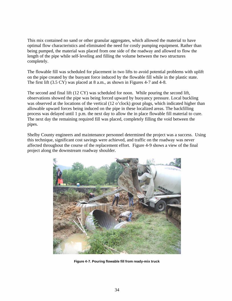
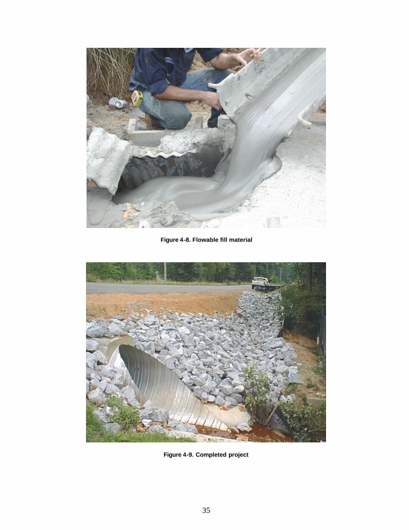
This mix contained no sand or other granular aggregates, which allowed the material to have optimal flow characteristics and eliminated the need for costly pumping equipment. Rather than being pumped, the material was placed from one side of the roadway and allowed to flow the length of the pipe while self- leveling and filling the volume between the two structures completely. The flowable fill was scheduled for placement in two lifts to avoid potential problems with uplift on the pipe created by the buoyant force induced by the flowable fill while in the plastic state. The first lift (3.5 CY) was placed at 8 a.m., as shown in Figures 4-7 and 4-8. The second and final lift (12 CY) was scheduled for noon. While pouring the second lift, observations showed the pipe was being forced upward by buoyancy pressure. Local buckling was observed at the locations of the vertical (12 o’clock) grout plugs, which indicated higher than allowable upward forces being induced on the pipe in these localized areas. The backfilling process was delayed until 1 p.m. the next day to allow the in place flowable fill material to cure. The next day the remaining required fill was placed, completely filling the void between the pipes. Shelby County engineers and maintenance personnel determined the project was a success. Using this technique, significant cost savings were achieved, and traffic on the roadway was never affected throughout the course of the replacement effort. Figure 4-9 shows a view of the final project along the downstream roadway shoulder.
Figure 4-7. Pouring flowable fill from ready-mix truck
35
Figure 4-8. Flowable fill material
Figure 4-9. Completed project
36
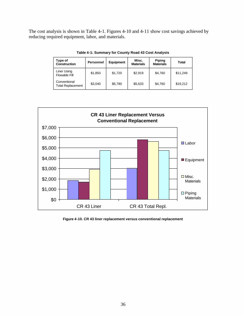
The cost analysis is shown in Table 4-1. Figures 4-10 and 4-11 show cost savings achieved by reducing required equipment, labor, and materials.
Table 4-1: Summary for County Road 43 Cost Analysis
Type of Construction Personnel Equipment Misc.
Materials Piping
Materials Total
Liner Using Flowable Fill
$1,850 $1,720 $2,919 $4,760 $11,249
Conventional Total Replacement $3,040 $5,780 $5,633 $4,760 $19,212
CR 43 Liner Replacement Versus Conventional Replacement
$0
$1,000
$2,000
$3,000
$4,000
$5,000
$6,000
$7,000
CR 43 Liner CR 43 Total Repl.
Labor
Equipment
Misc.Materials
PipingMaterials
Figure 4-10. CR 43 liner replacement versus conventional replacement
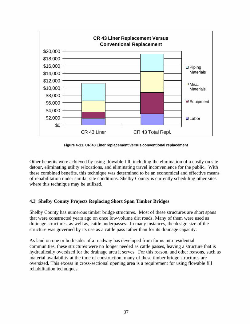
37
CR 43 Liner Replacement Versus Conventional Replacement
$0$2,000$4,000
$6,000$8,000
$10,000$12,000$14,000$16,000$18,000$20,000
CR 43 Liner CR 43 Total Repl.
PipingMaterials
Misc.Materials
Equipment
Labor
Figure 4-11. CR 43 Liner replacement versus conventional replacement Other benefits were achieved by using flowable fill, including the elimination of a costly on-site detour, eliminating utility relocations, and eliminating travel inconvenience for the public. With these combined benefits, this technique was determined to be an economical and effective means of rehabilitation under similar site conditions. Shelby County is currently scheduling other sites where this technique may be utilized.
4.3 Shelby County Projects Replacing Short Span Timber Bridges Shelby County has numerous timber bridge structures. Most of these structures are short spans that were constructed years ago on once low-volume dirt roads. Many of them were used as drainage structures, as well as, cattle underpasses. In many instances, the design size of the structure was governed by its use as a cattle pass rather than for its drainage capacity. As land on one or both sides of a roadway has developed from farms into residential communities, these structures were no longer needed as cattle passes, leaving a structure that is hydraulically oversized for the drainage area it serves. For this reason, and other reasons, such as material availability at the time of construction, many of these timber bridge structures are oversized. This excess in cross-sectional opening area is a requirement for using flowable fill rehabilitation techniques.
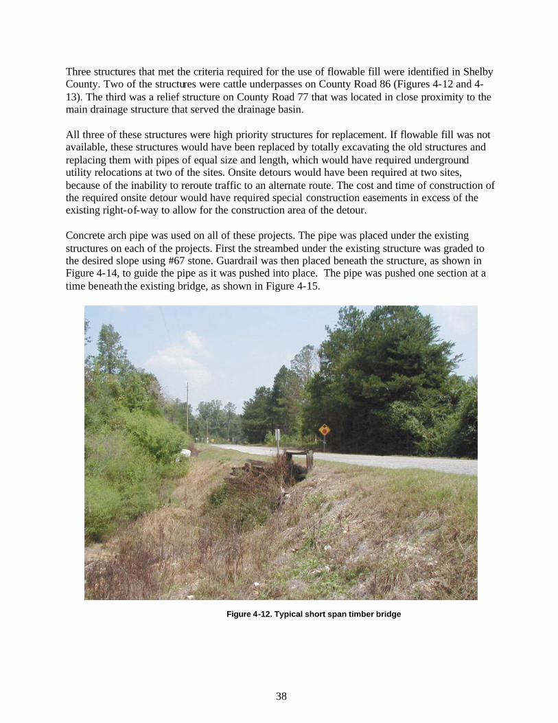
38
Three structures that met the criteria required for the use of flowable fill were identified in Shelby County. Two of the structures were cattle underpasses on County Road 86 (Figures 4-12 and 4-13). The third was a relief structure on County Road 77 that was located in close proximity to the main drainage structure that served the drainage basin. All three of these structures were high priority structures for replacement. If flowable fill was not available, these structures would have been replaced by totally excavating the old structures and replacing them with pipes of equal size and length, which would have required underground utility relocations at two of the sites. Onsite detours would have been required at two sites, because of the inability to reroute traffic to an alternate route. The cost and time of construction of the required onsite detour would have required special construction easements in excess of the existing right-of-way to allow for the construction area of the detour. Concrete arch pipe was used on all of these projects. The pipe was placed under the existing structures on each of the projects. First the streambed under the existing structure was graded to the desired slope using #67 stone. Guardrail was then placed beneath the structure, as shown in Figure 4-14, to guide the pipe as it was pushed into place. The pipe was pushed one section at a time beneath the existing bridge, as shown in Figure 4-15.
Figure 4-12. Typical short span timber bridge
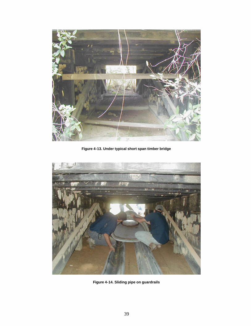
39
Figure 4-13. Under typical short span timber bridge
Figure 4-14. Sliding pipe on guardrails

40
Figure 4-15. Siding pipe under old bridge one with backhoe Fibered tar sealant was used to seal the joint between sections of pipe as they were placed beneath the existing structure. After the pipe was positioned under the structure at the desired location, the joints were covered with cement grout internally and externally to ensure the flowable fill material would not leak into the liner pipe. Formwork was placed on each end of the pipe and backfilled with dirt to confine the flowable fill while in the plastic state. The flowable fill was placed in two separate lifts with a 24-hour time interval. The first lift was placed to the calculated spring line of the pipe. This was done to ensure that the buoyant force created on the pipe by the almost-liquid flowable fill did not cause the pipe to rise or float. Bracing from the top of the pipe to the bottom of the existing structure was used to prevent upward or lateral movement of the pipe. When the flowable fill arrived at the site, the flowability was tested to ensure that the mix was of the desired consistency. Water was added until a minimum flow measurement of 12 inches was obtained. This consistency requirement ensured proper placement and maximum self- leveling properties. After the first lift was placed to the desired depth, as shown in Figure 4-16, the flowable fill was allowed to cure for approximately 24 hours before the second and final lift was placed. Before placing the second lift, the temporary bracing on the top of the pipe was removed. For purposes of observing the flowability and ensuring that all voids between the existing stringers of the timber bridge were filled, holes were drilled through the pavement and deck of the existing bridge. The flowable fill material was then placed in one rapidly poured final lift, filling all the remaining vo ids between the new and old structure (Figure 4-17).
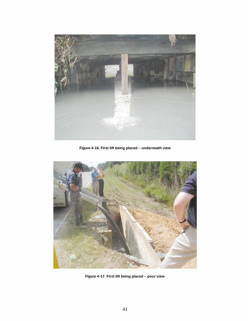
41
Figure 4-16. First lift being placed – underneath view
Figure 4-17. First lift being placed – pour view
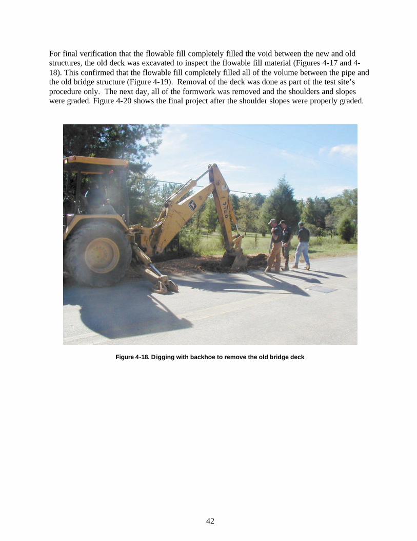
42
For final verification that the flowable fill completely filled the void between the new and old structures, the old deck was excavated to inspect the flowable fill material (Figures 4-17 and 4-18). This confirmed that the flowable fill completely filled all of the volume between the pipe and the old bridge structure (Figure 4-19). Removal of the deck was done as part of the test site’s procedure only. The next day, all of the formwork was removed and the shoulders and slopes were graded. Figure 4-20 shows the final project after the shoulder slopes were properly graded.
Figure 4-18. Digging with backhoe to remove the old bridge deck

43
Figure 4-19. Cutting old deck with chainsaw
Figure 4-20. Flowable fill completely encasing old bridge structure
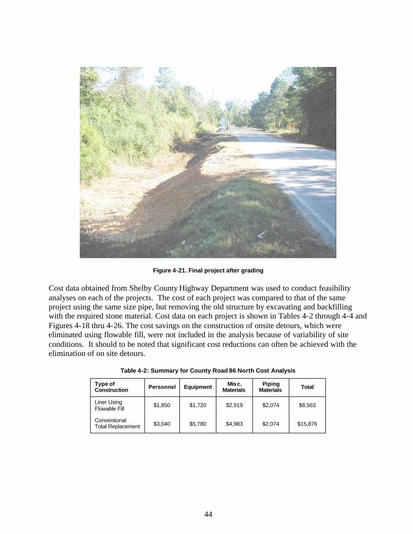
44
Figure 4-21. Final project after grading Cost data obtained from Shelby County Highway Department was used to conduct feasibility analyses on each of the projects. The cost of each project was compared to that of the same project using the same size pipe, but removing the old structure by excavating and backfilling with the required stone material. Cost data on each project is shown in Tables 4-2 through 4-4 and Figures 4-18 thru 4-26. The cost savings on the construction of onsite detours, which were eliminated using flowable fill, were not included in the analysis because of variability of site conditions. It should to be noted that significant cost reductions can often be achieved with the elimination of on site detours.
Table 4-2: Summary for County Road 86 North Cost Analysis
Type of Construction Personnel Equipment Mis c.
Materials Piping
Materials Total
Liner Using Flowable Fill
$1,850 $1,720 $2,919 $2,074 $8,563
Conventional Total Replacement $3,040 $5,780 $4,983 $2,074 $15,876
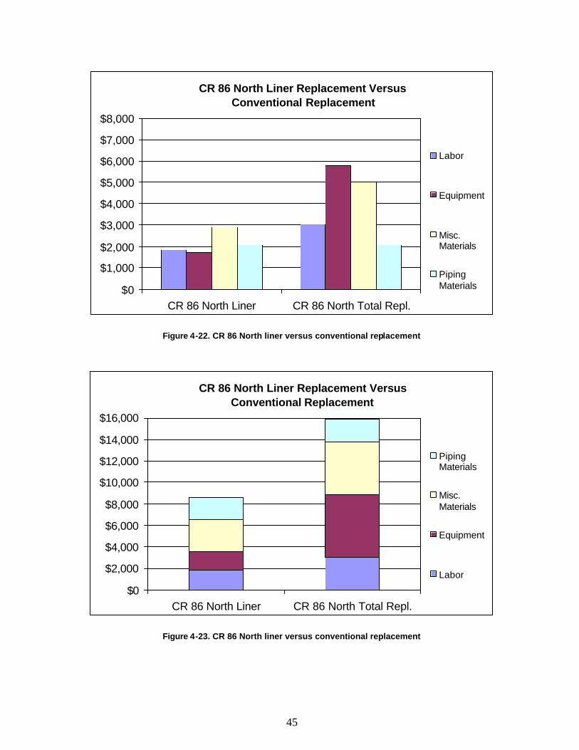
45
CR 86 North Liner Replacement Versus Conventional Replacement
$0
$1,000
$2,000
$3,000
$4,000
$5,000
$6,000
$7,000
$8,000
CR 86 North Liner CR 86 North Total Repl.
Labor
Equipment
Misc.Materials
PipingMaterials
Figure 4-22. CR 86 North liner versus conventional replacement
CR 86 North Liner Replacement Versus Conventional Replacement
$0
$2,000
$4,000
$6,000
$8,000
$10,000
$12,000
$14,000
$16,000
CR 86 North Liner CR 86 North Total Repl.
PipingMaterials
Misc.Materials
Equipment
Labor
Figure 4-23. CR 86 North liner versus conventional replacement
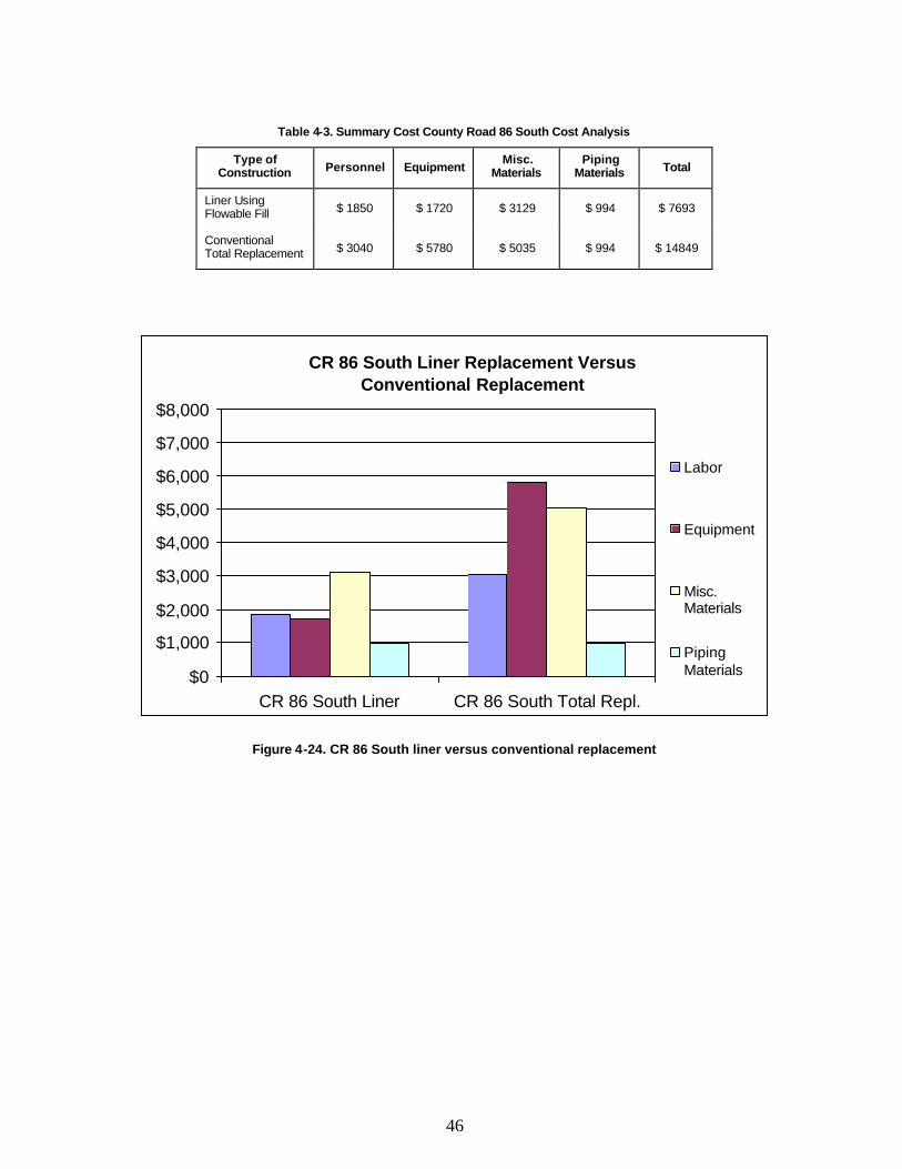
46
Table 4-3. Summary Cost County Road 86 South Cost Analysis
Type of Construction Personnel Equipment
Misc. Materials
Piping Materials Total
Liner Using Flowable Fill $ 1850 $ 1720 $ 3129 $ 994 $ 7693
Conventional Total Replacement $ 3040 $ 5780 $ 5035 $ 994 $ 14849
CR 86 South Liner Replacement Versus Conventional Replacement
$0
$1,000
$2,000
$3,000
$4,000
$5,000
$6,000
$7,000
$8,000
CR 86 South Liner CR 86 South Total Repl.
Labor
Equipment
Misc.Materials
PipingMaterials
Figure 4-24. CR 86 South liner versus conventional replacement
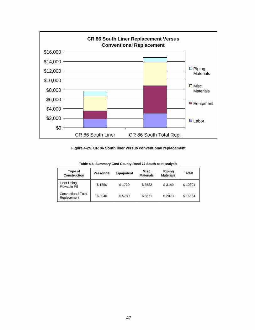
47
CR 86 South Liner Replacement Versus Conventional Replacement
$0
$2,000
$4,000
$6,000
$8,000
$10,000
$12,000
$14,000
$16,000
CR 86 South Liner CR 86 South Total Repl.
PipingMaterials
Misc.Materials
Equipment
Labor
Figure 4-25. CR 86 South liner versus conventional replacement
Table 4-4. Summary Cost County Road 77 South cost analysis
Type of Construction
Personnel Equipment Misc. Materials
Piping Materials
Total
Liner Using Flowable Fill $ 1850 $ 1720 $ 3582 $ 3149 $ 10301
Conventional Total Replacement $ 3040 $ 5780 $ 5671 $ 2073 $ 16564
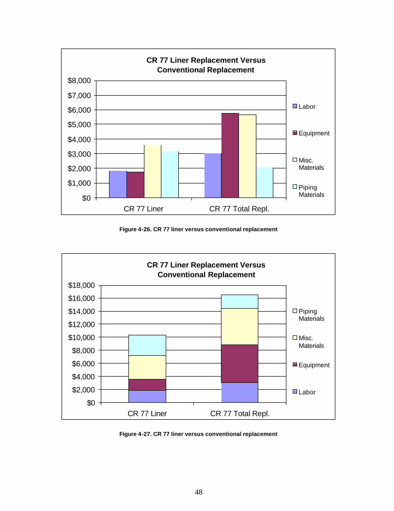
48
CR 77 Liner Replacement Versus Conventional Replacement
$0
$1,000
$2,000
$3,000
$4,000
$5,000
$6,000
$7,000
$8,000
CR 77 Liner CR 77 Total Repl.
Labor
Equipment
Misc.Materials
PipingMaterials
Figure 4-26. CR 77 liner versus conventional replacement
CR 77 Liner Replacement Versus Conventional Replacement
$0
$2,000
$4,000
$6,000
$8,000
$10,000
$12,000
$14,000
$16,000
$18,000
CR 77 Liner CR 77 Total Repl.
PipingMaterials
Misc.Materials
Equipment
Labor
Figure 4-27. CR 77 liner versus conventional replacement
49
4.4 Discussion of Shelby County Projects As a result of these demonstration projects, numerous county and ALDOT personnel have expressed interest in projects of this type. One ALDOT project involving a large abandoned cross drain structure was filled with flowable fill using some of the same techniques and flowable fill mix proportions that were developed during the course of this research. ALDOT and other county officials have indicated plans to replicate the Shelby County projects. Shelby County is currently planning additional projects that utilize flowable fill in the replacement of metal culverts and short span bridges. This technique is valuable in cases of deep cover depths and on routes with extremely high traffic volumes. In addition, overall project cost savings using flowable fill can be 45-50% less than that of conventional total replacement. When the criterion that is required for the use of flowable fill is present, it is proven to be an effective economic alternative for the replacement of culverts and short span bridges.
50
5. Summary, Analysis, and Construction Recommendations
5.1 Recommended Liner Material Use of liner pipes and flowable fill to replace existing deteriorated structures has proven to be a viable option. Highest benefits are realized when cover depths were large and onsite or alternate route detours were not economical, and when traffic volumes were greater than 1,000 VPD. One criteria for use of a liner pipe to replace an existing pipe, is that the existing drainage opening be oversized. The designer must check the hydrology of the drainage area to ensure that once the liner is in place, the opening of the pipe is large enough to carry the designated flood flow. Typically highway drainage structures are designed on a 25-year return period and checked for excessive effects on the roadway in the case of a 50 and 100-year return period. Because of constraints caused by existing structures, this return period may be severely limited or not satisfied in many instances. This negates the possibility of reducing the cross section by using liner techniques. In many cases, however, it may be determined that the existing structure exceeds the capacity required by the design flood frequency. For such cases, liners can prove to be a feasible technique for the rehabilitation or replacement of drainage structures. This project demonstrated that the selection of the liner pipe is critical to the success of a rehabilitation project. The site conditions play a critical role in the selection of the liner type and size. The first step in selecting a liner size and type is to determine the maximum opening size available inside the existing structure for the placement of the liner pipe. This can be done by measuring cross sections along the existing structure at five-foot intervals along its entire length to ensure the opening area and linearity are suitable. The piping material is dependent on limitations of the size openings of the existing structure. If the size of the existing opening can be reduced considerably, reinforced concrete pipe may be used as the liner. The construction procedure used on Shelby County roads 86 and 77 proved to be successful and is recommended under similar site conditions. If the opening reduction must be kept to a minimum, galvanized or aluminized metal pipe is typically used. The Shelby County project on County Road 43 proved that under similar site conditions, Contech Construction Product’s “Ultra Flow” metal pipe with prefabricated grout plugs could be successful when metal pipes with limited allowable size reductions are available. Ultra-Flo aluminized pipe is often used where reductions in opening size is critical to the performance of the structure. This material is constructed using special low-rise ribs, unlike typical corrugated metal piping. This offers an extra smooth surface with a tested Manning’s “n” coefficient of 0.012, which is compatible to concrete piping. Although the price is typically higher than other metal piping materials, the benefit of the 0.012 Manning’s n may be essential to meet the hydraulic requirements of certain structures.

51
If a project involves multiple pipes being lined simultaneously or consecutively, the water must carefully be rerouted during the construction. The Wadley project involved three large diameter pipes being lined one after the other. While the first two were under construction, the drainage creek was re-routed through the third pipe. It is important to make sure the earthen dam used is sufficient to keep water from breaking through and flooding the pipes under construction. It is also important to plan phases of construction, and to consider the possibility that a storm event could cause damage to the job. This includes, but is not limited, to extending earth barriers and in some cases providing high capacity pumps to manage the water. Once the first pipe in a series is completed, the water can be rerouted through it while the remaining pipes are completed. Before the flowable fill is placed, the liner pipe or culvert must be braced to resist the upward buoyant force created by the flowable fill. As previously discussed, metal rods may be used in conjunction with prefabricated grout plugs when using metal pipe as the liner material. Placement of the grout plugs at five-foot intervals alternating on the 9, 12 and 3 o’clock positions was determined to be adequate. There are numerous methods to successfully brace the liner pipe based on the type of liner used and the conditions associated with the existing structure. To minimize this upward buoyant force, it is recommended to place the flowable fill in more than one lift. The first lift should be placed at or just below the calculated spring line of the liner pipe. It is also important to ensure that as the fill is poured, the level of fill is equalized on each side of the pipe. To ensure the flowable fill self- levels, water should be added at the jobsite until a minimum flow measurement of 12 inches is achieved. After the fill hardens, the shoulder and slopes can be easily graded to the desired widths and grades. 5.2 Recommended Flowable Fill Mix Two different flowable fill mixes were used during this research. The flowable fill in the Wadley project consisted of sand, fly ash, cement and water. These mix proportions required the use of costly pumping equipment to ensure the material completely filled the volume between the new and old structures, because of the limited flowability of the larger gradation of the sand that made up the majority of the mix design. The flowable fill mix used on the Shelby County projects consisted of fly ash, cement and water. The use of large quantities of fly ash, rather than sand, allowed the flowable fill to be much more liquid. The increased flowability allowed the material to be placed from one side of the roadway, completely filling the voids between the new and old structure without the use of costly pumping equipment. The large volumes of fly ash not only improved the desired physical properties of the mix, but it also aided in reducing the unit cost of the mix. By using non-spec fly ash material, the costs of the materials used in the mixes on the Shelby County projects were minimized. This material also provided an environmental benefit, because the by-product fly ash material that could not be used in concrete would otherwise be a useless material. Compressive strengths of each of the mixes were determined to be adequate as a substitute for traditional backfill.

52
5.3 Benefits Analysis There are number of advantages and benefits in using flowable fill for culvert and bridge rehabilitation and replacement. The two greatest factors are the cost savings due to the reduction in construction cost (materials, equipment and labor), and significant reductions in traffic disturbance. These are often the most critical factors in determining construction procedures. The following paragraphs summarize the benefits experienced in projects across the country that were identified in the literature review, as well as, in the projects investigated in Wadley and Shelby County in Alabama. Using flowable fill in culvert and bridge replacement results in significant savings in construction time. While time is obviously a factor in saving cost, it also represents a significant decrease in user inconvenience. Since the construction process using flowable fill does not require excavation of the roadway, road closure and required onsite or alternate route detours are eliminated. Using methods of removal and replacement requires a detour or an alternate route, and both can be costly and extremely time consuming. An on-site detour is essentially a temporary travel way constructed over a temporary drainage structure, built on site to manage traffic until the original bridge can be replaced. Flowable fill is usually placed from the ends on the side of the roadway. If the space is available on the shoulder or beside the roadway, the road can remain open throughout the construction process. If it is not possible to place the flowable fill from beside the roadway, it can be placed from a truck blocking one lane of traffic. This method eliminates the need for detours and allows work to proceed with a limited amount of traffic control. Using flowable fill, the projects investigated in this research provided a great benefit by saving construction time and expense, and by eliminating the need for a detour. In Wadley Alabama, the project was completed in approximately six months. Because of weather and scheduling delays, the project was estimated to have taken twice as long as would otherwise be required. The ALDOT project engineer indicated that a project equivalent to the Wadley project could be done in three months or less, if work was held constant without significant delays. The time required for this type project will decrease as workers become more experienced in this type of construction. In Shelby County, the replacement time of each project was greatly reduced using flowable fill. These projects typically took two to three days to excavate and replace the deteriorated structure. During the construction, there was a limited amount of time that traffic control was required. The flowable fill was poured from ready-mix trucks while blocking only one lane of traffic. As the crew became more experienced with the overall process, the overall construction time and project quality consistently improved. The only minor traffic disruption was the brief period when the truck was arriving on the jobsite and positioning to discharge its load. Although traffic control was used during this period, traffic
53
was never stopped for an extended period. At worst, traffic flow was maintained in one lane as the truck was positioned. The Wadley project and the Shelby County projects produced significant cost savings. The required labor force was generally half of that required for a typical replacement operation, and the duration of the project was significantly reduced, creating savings in payroll expenses. Also, there were significant reductions in the amount of heavy equipment required to install the liners. In many cases standard backhoe or track hoe was used to place the liner inside the existing structure. This eliminated the need for expensive cranes and operators that are often required for the placement of large precast concrete or metal drainage structures.
54
6. Conclusions and Future Research While it is evident that additional research on using high volume ash flowable fill would be beneficial, this project has demonstrated that using flowable fill in this type of construction is a viable construction alternative from engineering and economical standpoints. The projects investigated in this report using flowable fill have achieved exceptional results in project quality and decreased construction cost. Construction costs were found to decrease by approximately 40-50% compared to total replacement in most cases. With the initial success of this new construction technique for replacing highway drainage structures, it is evident that projects utilizing these methods should occur in the future. To promote this innovative method and to increase overall project quality and success, states are encouraged to use flowable fill as an approved construction material on state and federally funded projects. High-volume ash flowable fill not only makes use of a material that would otherwise be deemed a useless by-product, but it also has proven to be a valuable construction material with numerous applications, which are not limited to backfill for liner construction. With the increased interest in its use and the ready-mix industry’s interest in production, its use will continue to increase. As the associated advantages become better known in the construction industry, flowable fill should develop into a sustainable industry alternate to traditional backfilling and excavation stabilizing materials. It is important for state and county officials to develop an evaluation procedure to determine the potential for bridges to be repaired in place, using construction techniques developed as a part of this project. Because there are a number of construction methods using flowable fill, all options should be evaluated and optimized. Once counties begin using flowable fill, they will become familiar with the procedures, as have ALDOT’s Fourth Division and Shelby County. As construction forces and engineers become more familiar with the fill material and the process, they will be able to streamline construction, increasing overall project savings. This report serves as an initial guide and tool to be used to begin the implementation of flowable fill as a viable alternate construction material in highway culvert and bridge replacement.
55
7.0 References ACI (American Concrete Institute) 229R-94. Controlled Low-Strength Materials (CLSM). ACI Committee 229. Detroit, MI 1994. Alabama County Engineers Association, “The Crisis Continues, Needs Assessment for Alabama Counties”, ACEA Legislative Report, 1999. Alabama Department of Transportation, “Section 260 - Low Strength Cement Mortar,” October 1990. Buss, William. “Iowa Flowable Mortar Saves Bridges and Culverts.” Concrete and Construction New Developments and Management, Transportation Research Board National Research Council. Washington DC. 1989. City of Albuquerque, New Mexico, “Section 207 - Lean Fill Construction,” (no date provided). City of Lawrence, Kansas, “Flowable Mortar,” (no date provided). Clem, Don A., William Hook, and Jay Goldbaum. “Flowable Fill Makes Bridge Replacement Economical.” Concrete Journal. September 1995. Colorado Department of Highways, “Revision of Section 206 - Structural Backfill (Flow-fill),” (no date provided). Delaware Department of Transportation, “Section 213-Flowable Fill,” (no date provided). Florida Department of Transportation, “Section 121 - Flowable Fill,” July 1991. GCPA (Georgia Concrete and Products Association). “Flowable Fill…15 Reasons to Use,” http://www.gcpa.org/flowable_fill.htm, accessed March 2002. Last Update: Friday, November 10, 2000. Georgia Department of Transportation, “Section 600 - Controlled Low-Strength Flowable Fill,” Addition to the Standard Specifications, February 1995. Goldbaum, Jay E., William Hook, and Don A. Clem. “Modifications of Bridges with CLSM,” Concrete International. May 1997. Illinois Department of Transportation, “Special Provision for Controlled Low-Strength Material (CLSM),” effective January 1990.

56
Indiana Department of Transportation, “Section 213 - Flowable Mortar,” 1988. Iowa Department of Transportation, “Supplemental Specifications for Flowable Mortar,” November 1985. Kentucky Transportation Cabinet, “Special Note For Use of Flowable Fill As Pipe Backfill,” April 1993.
57
Larsen, R.L. “Use of Controlled Low-Strength Materials in Iowa,” Concrete International, July 1988. Maryland Department of Transportation, “Section 800, Incidental Construction, Interim Specifications Addenda to the Standard Specifications for Construction and Materials (1982) and to the Specifications Supplement (1988),” September 1991. MCIA (Mississippi Concrete Industries Association). Flowable Fill in Mississippi. The Backfill Solution. Ridgeland, MS. (888-957-5274), industry flyer, no date provided. Michigan Department of Transportation, “Specification FF-1, Specification for Flowable Fill,” July 1998. Michigan Department of Transportation, “Special Provision for Flowable Fill for Utility Trenches,” 1991. Mississippi Department of Transportation “Suggested Specification-Flowable Backfill Material,” (no date provided). Missouri Highway and Transportation Department Materials and Research, “Special Provisions - Flowable Backfill,” August 1992. New York Department of Transportation, “Low Strength Slurry Backfill,” Item 17502.9501, March 1992. Ohio Department of Transportation, “Item Special - Low Strength Mortar Backfill Material,” Proposal Note No. 220, October 1989. Oklahoma Department of Transportation, “Section 529S - Low Strength Backfill Material,” (no date provided). South Carolina Department of Highways and Public Transportation, “Specification for Flowable Fill (Specification 11),” March 1992. TDHPT (Texas Department of Highways and Public Transportation), “Innovations #8 Bridge Replacement Solution,” Technology Transfer, Austin, TX 1991. Tennessee Department of Transportation, “Special Provision Regarding Foundation Fill Material (Flowable Mortar),” Item No. 204B, August 1990. Virginia Department of Transportation, “Special Provision for Flowable Backfill,” May 1995.