informaci“n sobre costa rica para extranjeros
TRANSCRIPT

STATE OF THE PRACTICE REVIEW OF HEAP LEACH PAD DESIGN ISSUES
Richard Thiel, P.E., Associate, Vector Engineering, Inc., Grass Valley, CA, USA Mark E. Smith, P.E., G.E., Vice President South American Operations, Vector Engineering, Inc., Lima, Peru Keywords: mining; leach pad; geomembrane; liner system
ABSTRACT
The authors present a summary of the state of the practice of containment
design in copper and gold heap leaching, focusing on recent advancements and how these applications differ from the more conventional landfill design practices. Advancements both within the Americas and world-wide are presented, including consideration of increasing heap depths, which are now approaching 150 meters (with ore densities generally in the range of 1,500 to 1,800 kg/m3). Liner system performance under these pressures will be reviewed, including the latest developments in drainage pipe performance testing. The authors will also explore the recently emerging technology of using concentrated sulfuric acid pre-curing for copper ores and the related compatibility issues with conventional geomembrane materials.
INTRODUCTION
Heap leaching is a mineral processing technology whereby large piles of crushed or run-of-mine rock (or occasionally mill tailings) are leached with various chemical solutions that extract valuable minerals. The largest installations in terms of both land area and annual tonnage are associated with copper mines, where copper-containing minerals are irrigated with a weak sulfuric acid solution. This solution dissolves the copper from the mineral and the “pregnant leach solution” (PLS) passes down through the ore pile and is recovered at the bottom on the “leach pad,” which usually consists of a geomembrane liner, sometimes clay (either to create a true composite liner or more commonly as a good quality bedding layer for the geomembrane), and a permeable crushed rock drainage system called an “overliner”, with a drainage pipe network. In some applications (principally oxide copper ores) thin liners are installed between layers or “lifts” of ore to intercept the PLS earlier. Copper is extracted from the PLS using electrowinning processes and the acidic solution is recycled back onto the leach pile. Gold heap leaching is similar, except that the solvent is cyanide.

2
Leach pads can be divided into four categories: conventional or “flat” pads, dump leach pads, valley fills and on/off pads. Conventional leach pads are relatively flat, either graded smooth or terrain contouring on gentle alluvial fans such as in the Chilean Atacama desert, Nevada and Arizona, and the ore is stacked in relatively thin lifts (5 to 15 m typically). Dump leach systems are similar or can include rolling terrain; the term “dump” usually means that the lifts are much thicker (up to 50m). Valley fill systems are just that – leach “pads” designed in natural valleys using either a buttress dam at the bottom of the valley, or a leveling fill within the valley. The facility shown in Photo 1 includes a 100 m high buttress dam and will ultimately crest out with 300 m vertical from the toe of the dam to the crest of the heap, providing over 100 million tonnes of capacity.
Photo note: Lined area shown is approximately 65 ha. Ultimate area will be 150 ha. Slope on right side is 1.75h:1v inter-bench angle. Commissioned in 1988.
Photo 1: Andean Valley Fill Facility (4,000m Elevation)
On/off pads (also known as dynamic heaps) are hybrid systems. A relatively flat pad is built using a robust liner and overliner system. Then a single lift of ore, from 4 to 10 meters thick, is loaded and leached. At the end of the leach cycle the spent ore (“ripios” in most mining literature) is removed for disposal and the pad recharged with fresh ore. Usually loading is automated, using conveyors and stackers. In some cases bucket wheel excavators and conveyors are used in the unloading cycle, in others loaders and trucks are used. For on/off pads the critical design loads for the containment system come from the ore handling equipment, not the weight of the ore. Truck and loaders can apply wheel loads of up to 53 tonnes, with 24 tonnes being common.
Modern heap leaching practices represent an expanding technology that is
pushing the limits of known performance parameters and creating some of the

3
world’s largest man-made structures. This paper presents a brief overview of the technology from the point of view of geotechnical considerations related to slope stability, bottom lining systems, and bottom drainage systems. Some contrasts to landfill engineering are also made. BACKGROUND
The critical aspects of heap leach design, from a geotechnical and containment perspective, can be summarized as depth of the ore (or equipment loads for on/off pads), presence of water and local terrain. Heap leaching presents a combination of extreme base pressures and high moisture conditions not present in any other containment application. Often these sites, by virtue of being associated with mineralized ground, are in active geology. When heap leaching first became popular for gold recovery in the 1980’s, typical maximum ore depths were around 15 m. By 1990 that limit had been pushed by the copper industry to 50 m. Now essentially all heap leach designs have ultimate target depths of at least 50 m, several are in operation or construction with target depths of over 100 m, and at least two are in design for ultimate depths of 145 m and 230 m. Increasing heap heights are not just a matter of economics. Some sites simply do not have sufficient acceptable ground to allow thinner heaps. And the general trend, with drivers ranging from closure and reclamation costs to minimizing diversion of agricultural land and encouraging sustainable development, is to reduce the amount of land impacted by mining. A higher heap means fewer hectares of disturbance.
While landfills are generally operated such as to minimize the presence of
water, heaps are actively irrigated to recover the target metals. Leach solution application rates are designed to optimize metal recovery and chemical consumption. Further, many new operations are already located in or planned for the tropics, including northern Peru, equatorial Brazil, Central America and west Africa, where annual rainfall can exceed 3,000 mm. The results are elevated phreatic levels over the base liner; usually (for conventional pads) of about 1 meter but, in at least one case, over 10 meters. Valley fill designs require very high solution levels during at least part of the operating year, and in extreme cases this can reach some 60 m above the liner

4
Table 1: Summary of Key Geotechnical Concerns of Leach Pads & Heaps Performance
Area Key Concerns
Slope Stability
Global and deep-seated failures due to extreme heights and base pressures
Sliding block stability along geomembrane interfaces Effects of active leaching, with elevated degrees of saturation Long-term chemical and biological degradation of ore First-lift stability affected by lift thickness (5m to 50m) and
stacking direction1 Liquefaction Earthquake-induced failures
Possible static liquefaction flowslides Water Management
Tropical installations can have large surplus water balances Designs include interim catch benches and temporary caps Phreatic levels range from 1 to 60m over the base liner
Liner Durability & Leakage
Coarse rock “overliner” systems Extreme pressures caused by weight of heap and equipment Durability against chemical attack – especially for 96%
H2SO4 Valley fill systems create very high solution levels
STABILITY
Global slope stability evaluations of leach piles are performed using standard geotechnical engineering principles. Standard circular- and block-type failure analyses are typically conducted with computer-based limit-equilibrium techniques, such as Spencer’s method. Since the piles may become locally saturated from leach solution irrigation, the potential for liquefaction also exists and is often considered. Further, the largest heap leaching area of the world, northern Chile and southern Peru, are also the most seismically active. The Chilean Atacama desert is the site of the largest earthquake ever recorded: 9.5 Richter magnitude in May, 19602.
1 Smith, M.E. and J.P. Giroud, Influence of the Direction of Ore Placement on the Stability of Ore Heaps on Geomembrane-Lined Pads, published in Slope Stability in Surface Mining, Ch. 49, Society of Mining Engineers, Hustrulid, W.A., M.K. McCarter and D.J.A. van Zyl, eds, 2000. 2 USGS Earthquakes Hazards Program: neic.usgs.gov/neis/eq_depot/world/1960_05_22.html

5
Photo note: right side is active heap, center and left is new pad area.
Photo 2: Conventional Leach Pad, Northern Chile (3,400m Elevation) Standard Static Stability Issues with Larger Leach Piles
As leach piles increase in height, there are several issues that confront the geotechnical practitioner charged with evaluating their stability. For some of these issues there is no strong experience on which to base factor-of-safety margins and reliability estimates, and practitioners are finding themselves at the cutting edge of laboratory testing, field observation, and engineering judgment in providing recommendations to owners and operators. The following specific issues exist:
Deeper fills require expanded limits of shear strength testing. Typically, the shear strength envelope is curved over a broad range of normal stresses, and the secant friction angle decreases as the normal stress increases. For practical purposes, it is always non-conservative to extrapolate shear strength parameters, either higher or lower, from the normal load range under which they were determined. These principles apply both to the

6
internal strength of the ore material, and to the interface with the geomembrane liners.
The larger, deeper leach piles, especially for dump leach facilities that tend to process low grade and “salvaged” ore and use very thick lifts, typically have a greater variability in ore quality. This variability must be accounted for in the factor of safety or reliability estimates for slope stability. The thicker lifts can lead to more particle-size segregation during dumping, with the larger rocks collecting at the outer face and toes of the lifts. This can result in heterogeneous shear strength and preferential flow paths, or channeling, within the piles. This internal focusing of fluids could in turn lead to localized pore pressure buildups or static liquefaction triggers.
Ore degradation caused by mineral dissolution and bacterial action through the leaching process is always a concern with leach piles. To date, no reliable testing has been developed for long-term performance, and rules of thumb developed for 50 m deep oxide heaps are being adapted to 150 m deep sulfide heaps. The effects of ore degradation can include:
o Decrease in shear strength of the ore and along geosynthetic interfaces;
o Lowering of ore permeability and increased degrees of saturation; and,
o Increased fines migration and the potential for filter incompatibility.
Inter-lift liners are becoming more common, principally as a tool to reduce the consumption of expensive sulfuric acid (for oxide copper ores). These can be spaced as close as each 2 m vertically, but 4 to 8 m is more common. These create both weak shear plans and perched water within the heap.

7
Photo note: Top of base liner, upper left corner, is at 4,120m elevation. Crest of dam, center-right, is at 3,900 m elevation. The valley slopes average 2h:1v and are locally as steep as 1.25h:1v. Over-cut benches are 0.5h:1v for up to 10m vertically.
Photo 3: Andean Valley Fill Showing Base Liner & Temporary Cap Liquefaction Potential
Liquefaction typically occurs when saturated, loose granular material contracts, or collapses, under some triggering event. A classic triggering event is seismic shaking. Seismically-induced liquefaction is typically limited to approximately 20 m in depth, as the confining pressures at greater depths reduce susceptibility to this type of failure.
Liquefaction flowslide failures have also been known to occur under static
conditions, particularly within the mining industry. Flowslides are of particular interest because of their terrible, destructive history. In the last four decades the mining industry has averaged one killer flowslide each 5 years with an average of 50 deaths per event. These have typically involved tailings piles and coal waste dumps. Empirical models to evaluate and predict these events are just being developed3,4. Some of the common factors from these models, suggesting a risk of
3 Dawson, R.F., N.R. Morgenstern and A.W. Stokes, Liquefaction Flowslides in Rocky Mountain Coal Mine Waste Dumps, Canadian Jr of Geotech Eng, 1998. 4 Olson, S.M. and T.D. Stark, Yield Strength Ratio and Liquefaction Analysis of Slopes and Embankments, Jr of Geotech and Geoenv Eng, ASCE, August 2003).

8
static liquefaction failure, are summarized in Table 2. To the authors’ knowledge there have been no cases of static flowslide liquefaction in leach piles, although dynamic liquefaction caused by an earthquake has been documented5 , 6 . The traditional method of stacking and irrigating in thin lifts promotes pre-collapse of the material, making the piles less susceptible to liquefaction. With leach dumps being constructed in thicker lifts the potential for static liquefaction increases. Table 2: Indicators of Flowslide Susceptibility7,8
Parameter or characteristic Threshold (approximate)
Maximum height
Foundation slope
Location, Terrain
Inter-bench slopes
Heaped moisture content of ore
Saturated permeability of ore
Saturation (at any point in the heap) Other factors:
≥ 100 m
≥15 degrees
Incised valley
Near angle of repose
≥ 5%
≤ 1 x 10⁻² cm/sec
≥ 85%
• No toe support • Finer material near the base • Water, impermeable layer at
base
For liquefaction it is required that the material be saturated (usually defined as a minimum degree of saturation of S = 85%). Therefore, a good first step in evaluating liquefaction susceptibility is to estimate the degree of saturation within the heap. This can be done by comparing the solution application rate with the ore hydraulic conductivity. The typical application rate for copper leach solutions is between 1×10⁻⁴ cm/s and 5×10⁻⁴ cm/s. Unsaturated hydraulic conductivity is typically less than the saturated hydraulic conductivity, but it is usually easier to 5 Rodriguez-Marek, A., P. Repetto, J. Wartman, D. Baures, E. Rondinel, J. Williams, and J. Zegarra-Pellanne, Geotechnical Earthquake Engineering Reconnaissance of the June 23, 2001, Southern Peru Earthquake: A Preliminary Report, hosted by Pacific EQ Engrng Research Center (PEER), 2001. 6 Preliminary Observations of the Southern Peru Earthquake of June 23, 2001, EERI Special Earthquake Report, Nov. 2001. 7 Smith, M.E., Copper Dump Leaching, published in Mining magazine, July, 2003. 8 Smith, Mark E., Technological Advances in Low Grade Leaching, ExpoMin 2002, Santiago, Chile, May, 2002.

9
measure the saturated hydraulic conductivity of a material. Given these relationships, which would need to be evaluated on a project-specific basis, the authors currently believe that the ore’s saturated hydraulic conductivity should be at least 10 times greater than the application rate to have a low probability for creating a saturated condition. In the case of copper mining ore, this would mean having saturated ore hydraulic conductivities of about 5×10⁻³ cm/s under the estimated confining pressures that will exist in the field.9 While this represents a reasonable initial condition for many projects, lower permeability zones can occur due to ore variability and degradation. GEOMEMBRANE PUNCTURE
The most common geomembrane material used for leach pad construction is 1.5 mm polyethylene (both HDPE and LLDPE); thicker PE is used occasionally for deeper heaps and 0.75 to 1.0 mm PVC is also occasionally used. (Much thinner liner material is used for the so called interlift liners). A typical grain size distribution for the “overliner” drainage material is nominal minus 25 to 38 mm sieve and having a saturated hydraulic conductivity of at least 1 x 10⁻² cm/s. Typically the material is well-graded and angular. Given overburden pressures that may exceed 2,000 kPa (see Table 3 for summary of recent pad heights and geomembranes used), any of the empirical design approaches developed in the solid waste industry for geomembrane puncture protection would inevitably result in a significant cushion requirement. Yet it is almost unknown for a cushion fabric to be used to protect the geomembrane in leach pad applications. How is this justified?
A cushion fabric increases costs and, more importantly, weakens the key
shear plane supporting the heap. With heaps of 100m and higher constructed on sloping ground, the use of a cushion fabric would result in serious instability issues. Further, leach pads are huge by any comparison: two projects currently under design, one in Chile and one in Peru, are considering leach pads of 150 to 200 ha in area. Thus, even a relatively low unit cost geotextile results in a very large total cost. Thus, before an engineer can recommend such a design feature, there must be compelling evidence of its need. Further, many of the mining sites are in environmentally “insensitive” areas. Consider, for example, the area near Antofagasta, Chile, one of the principal copper mining districts. At one site groundwater was 100 m deep and saline. Moving inland, the water table deepens until it essentially disappears. Superficial soils contained up to 20% naturally
9 Note that an even more conservative susceptibility limit of k = 1×10⁻² cm/s, as listed in Table 2, is used by some industry practitioners as an indicator of possible liquefaction.
10
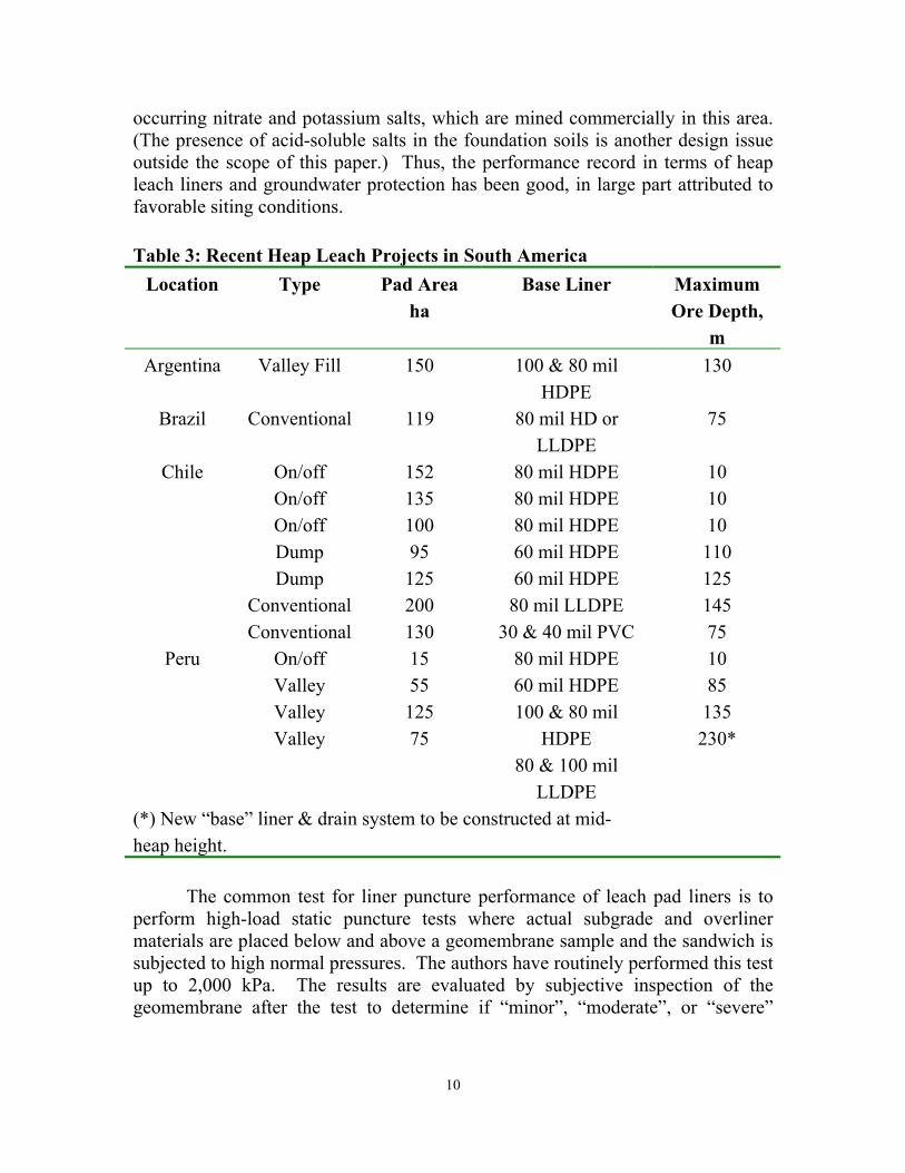
occurring nitrate and potassium salts, which are mined commercially in this area. (The presence of acid-soluble salts in the foundation soils is another design issue outside the scope of this paper.) Thus, the performance record in terms of heap leach liners and groundwater protection has been good, in large part attributed to favorable siting conditions.
Table 3: Recent Heap Leach Projects in South America
Location Type Pad Area ha
Base Liner Maximum Ore Depth,
m Argentina Valley Fill 150 100 & 80 mil
HDPE 130
Brazil Conventional 119 80 mil HD or LLDPE
75
Chile
On/off On/off On/off Dump Dump
Conventional Conventional
152 135 100 95 125 200 130
80 mil HDPE 80 mil HDPE 80 mil HDPE 60 mil HDPE 60 mil HDPE 80 mil LLDPE
30 & 40 mil PVC
10 10 10 110 125 145 75
Peru
On/off Valley Valley Valley
15 55 125 75
80 mil HDPE 60 mil HDPE 100 & 80 mil
HDPE 80 & 100 mil
LLDPE
10 85 135 230*
(*) New “base” liner & drain system to be constructed at mid-heap height.
The common test for liner puncture performance of leach pad liners is to
perform high-load static puncture tests where actual subgrade and overliner materials are placed below and above a geomembrane sample and the sandwich is subjected to high normal pressures. The authors have routinely performed this test up to 2,000 kPa. The results are evaluated by subjective inspection of the geomembrane after the test to determine if “minor”, “moderate”, or “severe”

11
dimpling of the geomembrane sample has occurred. The classifications of minor, moderate, and severe have been visually correlated in the past by the authors with multiaxial burst test results on geomembranes where minor dimpling or creasing has been shown to cause no degradation of the multiaxial strain performance, and severe dimpling or creasing causes a noticeable decrease in achievable strain. The 2,000 kPa normal stress capability in the authors’ laboratory represents 100 to 120 m of ore. Until recently this was beyond the design depths but recent advances have created a need for higher capacity laboratory equipment.
Photo note: White circles mark locations of incipient failure.
Photo 4: Lab Sample of 1.5mm HDPE, -38mm Overliner, 100m Heap
Most leach pads use single geomembrane liners, and a few use single composites. Therefore, there is little double-liner leakage data available. During the early 1990s there were, however, seven double geomembrane-lined conventional leach pads built in the Lahontan Region of California (located on the Eastern side of the Sierra) and two in South Dakota. Further, a large valley fill

12
facility in the Andes has a double-lined “internal” pregnant solution pond. In the case of the Lahontan facilities, the Regional Water Quality Control
Board imposed “zero leak” criteria and each facility was required to stop leaching and repair the liner whenever any leakage was detected between the liners. This is an unreasonable requirement for modern heaps, but in the case of the Lahontan heaps, which were under 15 m deep, this was a manageable (if illogical) requirement. Unfortunately, an excellent opportunity to collect real performance data was lost. In the South Dakota examples, both facilities operated for several years (their design lives) with measured leakage in the LDCRS of less than 200 liters per hectare per day (for predicted hydraulic heads of less than 300mm). In the case of the modern valley fill facility, the double-lined sump area comprises 38 ha, and has an operating liquid head of about 15 m during the dry season and 35 m during the wet season. Leakage rates are shown on Figure 1. The primary liner and drainage layer in this case consisted of 2.5 mm HDPE overlain by -38 mm crushed rock. The maximum heap height in this zone of the pad is about 100 m. These leakage rate data correlate well with the standards numbers of defects and leakage often assumed for MSW sites, especially considering the high head for the valley fill facility. SOLUTION COLLECTION PIPES
With leach pile heights in the 100 to 150 m range, the limits of known pipe performance have been long passed. Laboratory testing is struggling to keep up with each increase in the maximum depth.
Pipe survivability at depth is dependent on the deformation of the adjacent
soil. If the adjacent soil up to the top of the pipe were incompressible (imagine stable concrete) then no stress would be distributed to the pipe. The more compacted the soil, the less deformation and stress the pipe will receive. Terzaghi’s famous arching equation relates the stress on the pipe to the friction angle of the adjacent soil, presuming a granular soil. Most overliner material indeed is granular, and internal shear strengths of well over 35 degrees would be expected for the crushed stone usually employed at mine sites.

13
Figure 1: Leakage Rates v. Hydraulic Head over Primary Liner for Valley Fill (Liquid head between 15 m and 35 m.)
Even as the overburden depth tends towards infinity, there is a finite amount that the pipe and soil can deflect, which is determined by the initial soil porosity. Compacted soil should achieve less than 40 percent porosity. Therefore, in the worst case and assuming that the pipe structure does not collapse, the final pipe deflection should be less than 40 percent. Higher deflections should result in pipe collapse.
Actual high-load deflection tests have been performed by authors’
laboratory up to loads of 2,000 kPa. The tests are run in a box 750 mm wide by 600 mm deep by 500 mm high. The authors have run tests on 100 mm, 150 mm and 180 mm (4, 6 and 7 inch) I.D. double-wall corrugated PE pipe manufactured specifically for high-load installations. The surrounding soil represents expected or actual construction conditions and consists of crushed gravel with nominal maximum sizes ranging from 20 to 38 mm. Compactions were varied from 78% to 88% of standard Proctor. The test results have shown vertical deformations ranging from 6% to 54% of the initial pipe diameter, with a strong correlation existing between the initial degree of compaction and the vertical deformation (see Figure 2). Up to approximately 25% to 35% vertical deformation (depending on the pipe design), the pipe would show dimpling from the adjacent gravel, but no
-
5
10
15
20
25
30
35
40
0 500 1,000 1,500 2,000 2,500 3,000
Leakage Rate (liters per day per ha)
Hea
d ov
er li
ner (
m)

14
noticeable buckling. Above this level the pipe would begin to exhibit buckling and approach a “binocular” shape (see Figure 3). Obviously, as overburden loads increase above 2,000 kPa the survivability of pipes will be challenged even further. Figure 2: Typical Load-Deflection Curves for Dual-Wall PE Pipe
All pipe testing to date has been at standard laboratory temperature conditions. Recent data indicate that the chemical and biological reactions in the leach piles may cause temperatures up to 50°C to exist. The authors’ laboratory has just begun testing pipe under these elevated temperature conditions.
Heap or Dump Height (m)
0 10 20 30 40 50 60 70 80 90 100
60
70
80
90
100
110
120
130
140
150
160
0 200 400 600 800 1000 1200 1400 1600 1800 2000
Vertical Pressure (kPa)
Pip
e D
iam
eter
mm
)
Tub 110 mm (88% comp suelo)
Tub 160 mm (78% compac suelo)
Tub 160 mm (88% comp suelo)
Tub 180 mm (78% comp suelo)

15
Photo 5: PE Drain Pipe After 2,000 kPa Loading
(a) With 88% proctor compaction in haunch, 15% vertical deflection
(b) With 78% proctor compaction in haunch, 54% vertical deflection
Figure 3: Post-test Pipe Cross-Section After 2,000 kPa Loading
76 mm 86 mm
171mm
88%

16
GEOMEMBRANE COMPATIBILITY
There is a recent trend to used concentrated sulfuric acid to extract copper from tailings and leach piles, a practice only begun about 2 years ago. From this, compatibility problems with the geomembrane have been identified. One installation in Chile experienced significant softening of the HDPE geomembrane, and a series of laboratory tests that we conducted indicated about a 3% loss in tensile properties with very short term exposure (see Table 4)). A study completed about 6 years ago indicated that, in weak (1.6%) sulfuric acid, VLDPE exhibited a significant loss of physical properties10. Now operators are asking if they should expect the same from LLDPE, given the emerging information about HDPE. This issue aside, LLDPE is arguably the best liner for a broad range of copper heap leach applications.
Some of the polyethylene resin suppliers are concerned that the standard
antioxidant and packages may not be suitable for direct contact with concentrated H2SO4. Furthermore, the expected elevated temperatures, up to 50°C based on computer modeling, will exacerbate the situation. As a result of this information at least two HDPE geomembrane manufacturers are now recommending special additive packages for these applications.
Thus, the question really isn't whether there's a compatibility issue, but
rather how much exposure time is acceptable and whether available additives can help manage it. To help address this question, the authors have recently initiated a laboratory study to evaluate the compatibility of standard polyethylene and PVC liner materials with 96% concentrated sulfuric acid in accordance with standard ASTM procedures. This testing will use ASTM D5322 for the immersion procedure, at both standard (23oC) and elevated (50oC) temperatures. Immersed samples will contain both plain coupons and seams. ASTM D5747 is being used as guidance for performing index tests to evaluate the impact of the solution on the liner. Typical tests will include dimension changes, weight changes, visual observations, tensile properties, tear, puncture, secant modulus, hardness, density, seam peel and shear, NCTL, and OIT.
10 Smith, M.E., Copper Heap Leaching – A Case for PVC Liners, PGI Technical Bulletin, May 1997.

17
Table 4: Strength Loss with Short-Term Exposure11 Exposure Time in 96%
H2SO4 (days) Tensile Strength (% of original)
0 100%
1 98.3
4 97.4
8 97.3
Note: 1.5mm HDPE Geomembrane @ 23oC SUMMARY
The state of the practice in heap leach pad design is dynamic. Diverse issues push the envelope of known performance, including: 150 m high heaps, equipment loading of up to 53 tonnes per wheel, coarse rock overliner, concentrated acid exposure, hydraulic heads of up to 60 m, liquefaction and water management in tropical climates. Perhaps one of the largest drivers in this push is the fact that leach pads must be adjacent to the mineral deposits, and such deposits occur in unplanned locations. Often these are in aggressive terrain with active geology, presenting challenging geotechnical factors. As the better deposits are mined out and the industry searches for replacements, this trend will probably continue. The time required to “prove” a new technology is often longer than the time for industry to expand beyond a new limit. Consider, for example, that during the two years required to assemble a usable data base for pipe performance under 110 m heaps, the industry pushed the target depths to 145 m.
11 Smith, M.E., Reducción en ciclos de lixiviación sería posible, Peru Minero, Sept. 2003.