infm shaping x-rays by diffractive coded...
TRANSCRIPT

X-ray Coherence Berkeley, CA, 22-23 August 2003
TASC
INFMShaping x-rays by diffractive
coded nano-optics
INFM - TASC
For correspondence: Enzo Di FabrizioTASC-INFM @ Elettra Synchrotron Light Source, Lilit Beam-lineS.S.14 Km 163.5, Area Science Park, 34012 Basovizza - Trieste (Italy)Tel: +39-040-375-8417 Fax: +39-040-3758400E-mail: [email protected]
Enzo Di Fabrizio 1, Dan Cojoc 1,3, Stefano Cabrini 1,2, Burkhard Kaulich 2, Thomas Wilheim 4, Jean Susini 5
1 TASC-INFM @ ELETTRA Synchrotron Light Source,Trieste, Italy2 ELETTRA – Sincrotrone Trieste, Italy3 ‘Politehnica’ Univ. of Bucharest, Romania 4 RheinAhrCampus, Remangen, Germany5 European Synchrotron Radiation Facility, Grenoble, France

X-ray Coherence Berkeley, CA, 22-23 August 2003
TASC
INFM
Differential Interference Contrast (DIC) for XRM: purpose and main ingrediends
Fabrication of ZP Doublets
DIC measurements with ZPs Doublet
DOE for shaping X-ray
DOE for DIC measurements
DIC with variable phase shift
Outlook and future experiments
Outline

X-ray Coherence Berkeley, CA, 22-23 August 2003
TASC
INFM
Purpose for microscopy techniquesusing phase information
Amplitude and phase contrast for a model protein C94H139N24O31
Absorption contrast:
Phase contrast:
~E -3
~E -1
Use of phase shifting, real partof refractive index
• orders of magnitude higher contrast
• tremendous reduction of dose appliedto object
• additional transmission information onlow side of absorption edges (XANES,XRF !)

X-ray Coherence Berkeley, CA, 22-23 August 2003
TASC
INFMGeneral statements on DIC microscopy
Phase objects can be seen with great difficulty when in focus withordinary XRM (single ZP)
Phase objects retard or advance light that passes through them due to spatialvariation in their refractive index and/or thickness
Needs for DIC microscopyThe image of DIC microscopes is formed from the interference of two mutually
coherent waves with lateral displacements (shear) (of the order of the minimumsize of the imaged structure and are phase-shifted relative to each other.
Imaging characteristics. The intensity distribution in measured DIC images is given by a non
linear function of the spatial gradient of a specimen’s optical path length distribution along the direction of shear

X-ray Coherence Berkeley, CA, 22-23 August 2003
TASC
INFMDifferential Interference Contrast DIC
Visible light microscopy(Nomarsky set-up)
Shear of wave front division or distance of Airydisks in focal plane is smaller thanoptical resolution (“differential”)
DIC for X-ray microscopy with ZPs:
• Distance ∆f of both ZPs smaller than depth of focus• Displacement ∆s smaller than resolution δ
∆s < δ
∆f < D.O.F.

X-ray Coherence Berkeley, CA, 22-23 August 2003
TASC
INFM Differential Interference Contrast DIC
incident
ZP1 ZP2
substrateplane wave
detector0.
0. O1
O2
monochromaticx-rays
zone plate doublet
sample
detector planesubstrate
ZP1 ZP2
laterally displaced images
condenser
Working principle
TXM set-up

X-ray Coherence Berkeley, CA, 22-23 August 2003
TASC
INFM
Coherence considerations
Interference contrastInterference contrast XX--ray imaging using two zone ray imaging using two zone platesplates
Used setup: ∆y = 14 µm, D = 44 µm ∆s ≈ 0.01 µm, lcoh ≈ 1.5 µm
f -f1 2 f2
f12
2
221
21
2
2)(
)(2 fyff
ffys
⋅
⋅−=
−⋅∆
≈∆
Temporal coherence
∆s < coherence length lcoh
( ) yfffy ⋅
−=∆
2
21
Spatial coherence
∆y < coherently illuminated field D

X-ray Coherence Berkeley, CA, 22-23 August 2003
TASC
INFM Coherence considerations
Spatial coherence (Van Cittert-Zernike) Temporal coherence
D: Diameter of coherently illuminatedplane
d: Source diameterL: Distance to observation plane
D = 0.61 = 1.22 Lλd/2
fλδ
Then:If the separation(∆x) of the two
superimposed images is below the resolution limit (δ ) the two images
will interfere without further restrictions to the spatial coherence
of the source or, DIC works independent, of the spatial
coherence of the illumination
∆x < δ = 1.22 drNZP shift
lcoh = > N = ∆smaxλ2
2 ∆λλ2
lcoh : coherence length∆smax: path length differenceN: Number of zones
λ∆λ
> N ≈ Neff=(r+∆x)2
λf
Then:No precautions to the source
spectrum or other than for imaging with a single ZP
ZPs have to be treated to bein the same plane ( within theirdepth of focus) (N>100)
X-ray Coherence Berkeley, CA, 22-23 August 2003
TASC
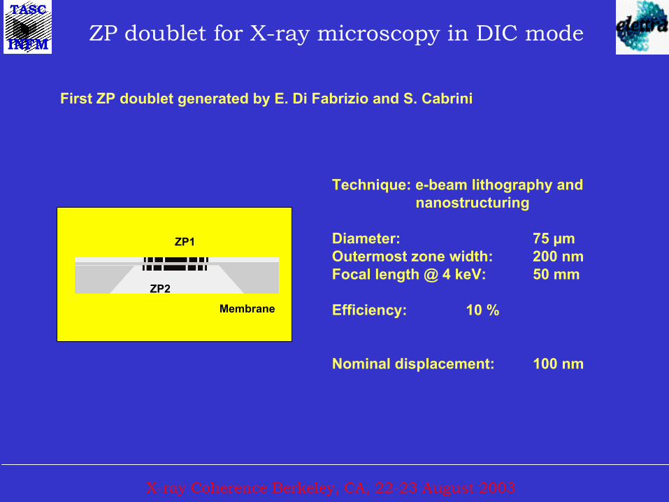
INFM ZP doublet for X-ray microscopy in DIC mode
First ZP doublet generated by E. Di Fabrizio and S. Cabrini
Technique: e-beam lithography and nanostructuring
Diameter: 75 µmOutermost zone width: 200 nmFocal length @ 4 keV: 50 mm
Efficiency: 10 %
Nominal displacement: 100 nm
Membrane
ZP1
ZP2

X-ray Coherence Berkeley, CA, 22-23 August 2003
TASC
INFM Alignment markers definition
Double face resist deposition
E-beam exposure
Developement
Electroplating and resist removal
On double face base platedSi3N4 membrane ( 1µm) Resist
Base plating
Si3N4 membrane
e-beam
To obtain self-aligned markers Self-aligned markers

X-ray Coherence Berkeley, CA, 22-23 August 2003
TASC
INFMDouble side ZP definition
Resist deposition
E-beam exposure
Electroplating and resist removal
“Front” side exposure aligned
to markers“Back” side exposure in controlled misalignment
“Back” side process“Front” side process
E-beam E-beam
X-ray Coherence Berkeley, CA, 22-23 August 2003
TASC
INFM
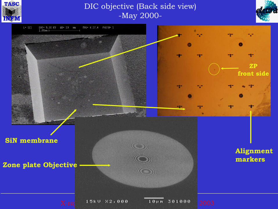
DIC objective (Back side view)-May 2000-
Zone plate Objective
Alignment markers
SiN membrane
ZP front side
X-ray Coherence Berkeley, CA, 22-23 August 2003
TASC
INFM
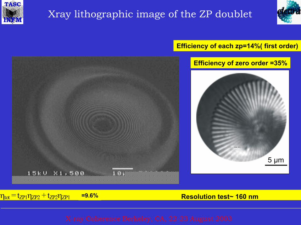
ηtot = tZP1ηZP2 + tZP2ηZP1 =9.6%
Xray lithographic image of the ZP doublet
Efficiency of each zp=14%( first order)
Efficiency of zero order =35%
5 µm
Resolution test~ 160 nm

X-ray Coherence Berkeley, CA, 22-23 August 2003
TASC
INFMDIC X-ray microscopy
with a full-field imaging microscope @ 4 keV
10 mµ
(a) (b)
(c) (d)
2 µm thick PMMA test structureswith a transmission of 98.8 % @ 4 keV
Absorption DICPixel
Inte
nsity
/ a.
u.
Contrast increase:x20 - x30
B. Kaulich, T. Wilhein, E. Di Fabrizio, S. Cabrini, F. Romanato, M. Altissimo, J. Susini (Nov 2000)

X-ray Coherence Berkeley, CA, 22-23 August 2003
TASC
INFMPMMA zone plate structure (250 nm)
2 micron thick:exposure time 10s
5 µm
Bright field X-DIC transmission

X-ray Coherence Berkeley, CA, 22-23 August 2003
TASC
INFMGeneral scheme of DOE shaping

X-ray Coherence Berkeley, CA, 22-23 August 2003
TASC
INFM DOE’s design
Numerical computation:
given a set of input data find the optimum output data which fit therequests
input data :•Source space: wavelength, size, geometry, intensity distribution
•Image space: intensity or/and phase or/and polarization field distribution
•DOE: size, resolution, material
output data:•DOE’s phase or/and amplitude function

X-ray Coherence Berkeley, CA, 22-23 August 2003
TASC
INFM
zo
Diffracting features
Propagation directionh
δD
Diffracted field in the plane z = zo
z
OK ! SW
DPW
Input fieldWavelength
Proportional phase delay
PDE profile
Outputplane
DOE’s phase function:
ΦDOE (x) = 2π (n-1) h(x) / λ
Diffractive optical element scheme
λ3d f
X-ray Coherence Berkeley, CA, 22-23 August 2003
TASC
INFMScalar versus Vectorial diffraction based models
Scalar based models•ray traycing, spherical wave propagation + superposition
•phase retrieval iterative algorithms (PRIA)
•global optimization methods: genetic algorithms, simulated annealing
Vectorial based models• Finite element method (FEM)
• Boundary element method (BEM)
• Method of moments (MOM)
• Finite-difference method (FDM)
• Finite-difference time-domain (FDTD)

X-ray Coherence Berkeley, CA, 22-23 August 2003
TASC
INFMSpherical wave approximation
Ns point sources
P1
PNs
P1
P2
Pg
PNg
DOE plane Image space
Source space
Array of Ng spots
xiyi
z

X-ray Coherence Berkeley, CA, 22-23 August 2003
TASC
INFM Comparison of the iterative algorithms
CEAAAAERA
SNR = - 10 log (MSE) MSE : Mean Square Error
[dB]
Intensity distribution
Phase DOE
CEA : Combined Error AlgorithmAAA : Adaptive Additive Algorithm
ERA: Error Reduction Algorithm

X-ray Coherence Berkeley, CA, 22-23 August 2003
TASC
INFM
a b c
Development of multi-spot X-ray DOE
Optical scheme and calculated layout
of 3 DOE’s that generate 2 and 4 spots
(a-b) on the same focal plane, and 2
spots along the same optical axis(c)
(d)Full beamshaping
The calculations are referred to a photon energy of 4 KeV and 5 cm focal length
a
b
c
monochromatic planewave illumination
OK !d

X-ray Coherence Berkeley, CA, 22-23 August 2003
TASC
INFM Development of multi-spot X-ray DOE
DIC visible light micrographof 4-spot ZP
Calculated pattern of a 4 spot ZP
DOE size 0.1 x 0.1 mm2, pixel size: 100 nm, energy 4 keV designed and generated by the Lilit beamline group (2001)

X-ray Coherence Berkeley, CA, 22-23 August 2003
TASC
INFMSEM pictures showing an overview of the DOE ( DOE area is 100x 100 µm2)
and details of the outermost area whose resolution is below 100 nm
Development of multi-spot X-Ray DOE

X-ray Coherence Berkeley, CA, 22-23 August 2003
TASC
INFM
Undulator
Double crystalmonochromator
2 spot DOEOSA
Rasterscanner
Off-axisphotodiode withaperture
(1,0)CS
Scanning X-ray microscope at ID21 beamline, ESRF
A S i p h o to d io d e w ith a 5 0 µ m ap e rtu re in fro n t w asp laced o n o n e f lan k o f an in te rfe ren ce frin g e in o rd e r tob e h ig h ly sen s itiv e to sh if ts o f th e frin g es re la ted too p tica l p a th d iffe ren ces in tro d u ced b y th e ra s te rscan n ed sp ec im en .

X-ray Coherence Berkeley, CA, 22-23 August 2003
TASC
INFM 2 spot DOE on SXTM at 4 KeV (February 2001)
2 µm thick PMMA test structureswith a transmission of 99 % @ 4 keV
Image taken with the scanningX-ray microscope at the ID21beamline, ESRF
Dwell time: 40ms / pxwith 200 x 200 px
Image contrast: 25% in DIC
1.10
1.05
1.00
0.95
0.90Inte
nsity
/ a.
u.
120100806040200Position / µm

X-ray Coherence Berkeley, CA, 22-23 August 2003
TASC
INFMScanning transmission X-ray microscopy
in DIC mode using a 2-spot ZP
200 x 200 px40 ms/px dwell
2 µm thickgrating structuresin PMMA
4 keV
Brightfield (BF) DIC1.15
1.10
1.05
1.00
0.95
0.90
0.85
Inte
nsity
/ a.
u.
50403020100Position / µm
1.15
1.10
1.05
1.00
0.95
0.90
Inte
nsity
/a.u
.
806040200Position / µm
2 µm
Contrast:
BF: 1 %DIC: 25 %

X-ray Coherence Berkeley, CA, 22-23 August 2003
TASC
INFM
Air Pollution SiO2 fiber Filter(Trieste)2 spot DIC&XRF measurements (July 2002)
Absorption contrast Diff. Interf. contrast
7.2 KeV X-ray 4 KeV X-ray
Cr XRF map Fe XRF mapCa XRF map K XRF map

X-ray Coherence Berkeley, CA, 22-23 August 2003
TASC
INFM Optical setup of DIC full field microscope

X-ray Coherence Berkeley, CA, 22-23 August 2003
TASC
INFM PMMA test structures (June 2001)test structures(a=squares, b=toroids) 1 µm thick with a transmission of 99.99 % @ 4
keV
Objective lens : ZP
2 confocalspots DOE
4 confocalspots DOE
2 coaxial spots DOE
10 µm
10 µm
a
b

X-ray Coherence Berkeley, CA, 22-23 August 2003
TASC
INFM Yeast cells: imaging in TXM at 4 keVby using diffractive optics
5 µm

X-ray Coherence Berkeley, CA, 22-23 August 2003
TASC
INFMComplete X-ray- beam shaping
Optical setup of DIC full field microscope
a

X-ray Coherence Berkeley, CA, 22-23 August 2003
TASC
INFMComplete X-ray- beam shaping (June 2001)
b
b - SEM image of the fabricated OK! DOE c - The intermediate image formed by the DOE at the focal plane located at 50 mm is magnified 150 times on a CCD detector by a ZP that acts as an objective lens
5 µm
10 µm
c

X-ray Coherence Berkeley, CA, 22-23 August 2003
TASC
INFM DIC Image formation with coherent illumination
Transmission function of the phase object
Ideal PSF from ray-tracing (geometrical optics)
=Shear in x direction
=constant phase bias
C. Preza et. al. J. Opt. Soc. Soc. Am. A/Vol. 16, No. 9. 1999

X-ray Coherence Berkeley, CA, 22-23 August 2003
TASC
INFM Field Intensity in the DIC image
If the shear very small (differential) comapared to the size of the detailsof the specimen (or the resolution of the ZP) ==> the phase difference can be written as a phase gradient:
With DOE is possible to control the contrast through the bias ∆Θ

X-ray Coherence Berkeley, CA, 22-23 August 2003
TASC
INFM Bias retardation in DIC
pixelspixels
Intensity(a.u.)
Phase(radians)
∆+
∂∂
∆= θφxyxxayxi ),(sin),( 2
(a) The phase function of a one dimensional object described in 250 pixels; (b) Intensity distributions obtained with the same shear ∆x= 2 but different bias values:
∆θ = 0 - first line, ∆θ = π/4 - second line, and ∆θ = 3π/4 - third line; the signals are offset by 2 a.u. for a clear representation
X-ray Coherence Berkeley, CA, 22-23 August 2003
TASC
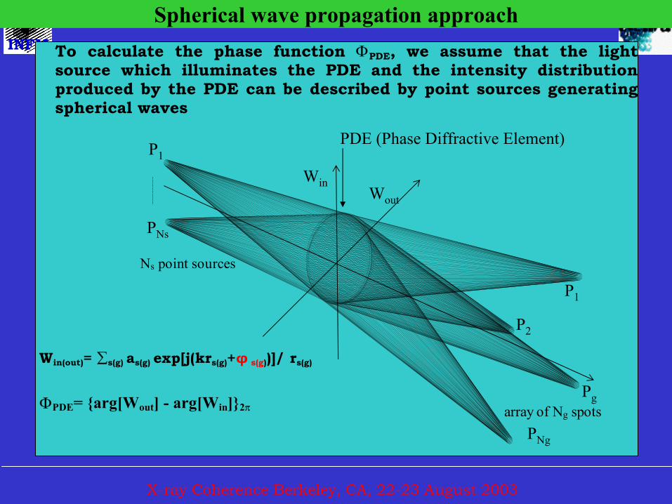
INFM To calculate the phase function ΦPDE, we assume that the lightsource which illuminates the PDE and the intensity distributionproduced by the PDE can be described by point sources generatingspherical waves
ΦPDE= {arg[Wout] - arg[Win]}2π
Ns point sources
array of Ng spots
P1
PNs
P1
P2
Pg
PNg
PDE (Phase Diffractive Element)
WinWout
Win(out)= ∑s(g) as(g) exp[j(krs(g)+φ s(g))]/ rs(g)
Spherical wave propagation approach

X-ray Coherence Berkeley, CA, 22-23 August 2003
TASC
INFM
DOEs producing the same beam shearing (1 mm) but different bias: a) no bias, b) bias = π at 1 m from the DOE (DOE size= 2 cm, described in 480 pixels)

X-ray Coherence Berkeley, CA, 22-23 August 2003
TASC
INFMThe intensity distribution obtained in the focal plane(∆x=1 mm λ=532 nm DOE made by Hamamatsu SLM)

X-ray Coherence Berkeley, CA, 22-23 August 2003
TASC
INFM
Phase distributions obtained in the focal plane of the DOE. For the 3D graphics(a,b) the phase is represented in radians on the z axis, the distances represented on x and y axes being expressed in microns. The phase distributions along the lines indicated in a) and b) are represented in the second line c) and d) clearly showingthe presence of the π bias
a) b)
c) d)
X
y
x
y

X-ray Coherence Berkeley, CA, 22-23 August 2003
TASC
INFMThe interference patterns obtained after the focal plane of the DOEs implemented on the phase SLM Hamamatsu; the left pattern corresponding to the DOE without bias is shifted with half of a fringe with respect to the right pattern which corresponds to the DOE with bias π

X-ray Coherence Berkeley, CA, 22-23 August 2003
TASC
INFM Complete set of objectives and condenser lens fabricatedBy e-beam lithography
2 spots at 6.5 KeV 50 nm res.
2 spots at 2.5 KeV 50 nm res.
Top hat condenser at 4 KeV 150 and 200 nm res.
Work in progress

X-ray Coherence Berkeley, CA, 22-23 August 2003
TASC
INFM ∆Θ=0 ∆Θ=π/2
∆Θ= π ∆Θ= 2π/3
DOE for Bias control

X-ray Coherence Berkeley, CA, 22-23 August 2003
TASC
INFMc
10 µm
Further DOE already fabricated to be tested
• Top Hat for TXM microscope (to replace the conderser lens)
•New annular distribution forDIC microscopy
•Sub micron Intensity patternfor maskless lithography andCVD induced by X-rays

X-ray Coherence Berkeley, CA, 22-23 August 2003
TASC
INFM50 nm smaller pixel size with 30 nm details
30 nm
50 nm

X-ray Coherence Berkeley, CA, 22-23 August 2003
TASC
INFM Outlook and future investigations
Two different DIC techniques using ZP doublet and X-Ray DOE
Spatial resolution according to the design
Technique has no limitation in spectral range as far as ZPs can be applied
Full beam shaping achieved at X-ray wavelength
Future investigations:
Extension of experiments to soft and harder X-rays
Resolution limit toward state-of-art- fabrication technique
Theoretical investigations and simulations (transfer function)
Combination with spectro-microscopy for biological samples

X-ray Coherence Berkeley, CA, 22-23 August 2003
TASC
INFM Acknowledgements
L. Vaccari, M. Altissimo, L. Businaro, P. Candeloro
TASC-INFM at ELETTRA, LILIT, Italy
O. Dhez, B. Fayard, U. Neuhaeusler, M. Salome, R. Baker
ESRF, ID21, Grenoble, France
F. Polack, D. Joyeux,
Lure Universite Paris-Sud & IOTA, Orsay, France
F. Perennes, A. Barinov, M. Kiskinova
Sincrotrone Trieste SCpA – ELETTRA, Italy