industrial accessories catalog 551444 revision c€¦ · 7.8 power supply for canbus, ethercat®,...
TRANSCRIPT

Temposonics®
Magnetostrictive Linear Position Sensors
Accessories for industrial sensorsCatalog

Temposonics® accessories for industrial sensorsCatalog
Table of contents
1. Position magnets .............................................................................................................................................. 31.1 Ring magnets ............................................................................................................................................................................................ 31.2 U-magnets ................................................................................................................................................................................................. 61.3 Magnet sliders ........................................................................................................................................................................................... 71.4 Block magnets ........................................................................................................................................................................................... 91.5 Floats ......................................................................................................................................................................................................... 9
2. O-rings..........................................................................................................................................................133. Back-up rings ..................................................................................................................................................144. Mounting accessories ........................................................................................................................................14
4.1 General accessories ................................................................................................................................................................................. 144.2 Optional pressure rods for R-Series RF sensors ..................................................................................................................................... 174.3 Optional profile for R-Series RF sensors ................................................................................................................................................. 19
5. Connectors .....................................................................................................................................................215.1 Overview ................................................................................................................................................................................................. 215.2 M8 connector .......................................................................................................................................................................................... 235.3 M12 connectors ...................................................................................................................................................................................... 235.4 M16 connectors ...................................................................................................................................................................................... 255.5 Connection accessories ........................................................................................................................................................................... 27
6. Cables ..........................................................................................................................................................296.1 Pigtailed cables ....................................................................................................................................................................................... 296.2 Cable sets ................................................................................................................................................................................................ 32
7. Cable configurator ............................................................................................................................................377.1 Structure ................................................................................................................................................................................................. 377.2 Analog ..................................................................................................................................................................................................... 387.3 Start / Stop ................................................................................................................................................................................................ 397.4 CANbus ................................................................................................................................................................................................... 407.5 SSI .......................................................................................................................................................................................................... 417.6 EtherCAT® / EtherNet/IP™ / Powerlink / Profinet ..................................................................................................................................... 427.7 Profibus ................................................................................................................................................................................................... 437.8 Power supply for CANbus, EtherCAT®, EtherNet/IP™, Powerlink, Profibus & Profinet ............................................................................ 44
8. Programming tools ...........................................................................................................................................459. TempoLink smart assistant for R-Series V ..............................................................................................................49

Temposonics® accessories for industrial sensorsCatalog
I 3 I
Drawing Name & part number Description Series
Ø 32.8(Ø 1.29)
Ø 23.8(Ø 0.94)
Ø 13.5(Ø 0.53)
Ø 4.3(Ø 0.17)
7.9(0.31)
Ring magnet OD33Part no. 201 542-2
Material: PA ferrite GF20Weight: Approx. 14 gSurface pressure: Max. 40 N/mm2
Fastening torque for M4 screws: 1 NmOperating temperature: −40…+105 °C (−40…+221 °F)
E-Series
EH, EE, ET
G-Series
GH, GT, GTE
GB-Series
GB
R-Series
RH, RD4, RT4
R-Series VRH5
T-Series
THR
Ø 63.3(Ø 2.49)
Ø 41.3(Ø 1.61)
Ø 19(Ø 0.75)
Ø 4.6(Ø 1.6)9.5
(0.35)
Ring magnet OD63.5Part no. 201 554
Material: PA 66-GF30, magnet slugspotted with epoxyWeight: Approx. 35 gSurface pressure: Max. 20 N/mm2
Fastening torque for M4 screws: 1 NmOperating temperature: −40…+75 °C (−40…+167 °F)
E-Series
EH, EE, ET
G-Series
GH, GT, GTE
GB-Series
GB
R-Series
RH, RD4, RT4, RF
R-Series VRH5
T-Series
TH
1.1 Ring magnets
1. Position magnets
Controlling design dimensions are in millimeters and measurements in ( ) are in inches
Recommended accessories are marked with the following sign:
Introduction
This brochure provides an overview of accessories for our industrial sensors. It supplements the specifications in the data sheets and operating manuals of the individual sensors. For each accessory, it is specified exactly for which sensor it is suitable and which one has been used most. So you can quickly and easily find the right accessories for your MTS sensor.In order to simplify the search, the articles are sorted in ascending order according to their 6-digit part number.

Temposonics® accessories for industrial sensorsCatalog
I 4 I
Drawing Name & part number Description Series
Ø 22(Ø 0.86)
Ø 13.15(Ø 0.51) 28
(1.1)
System magnetPart no. 253 928
Material: Composite POMWeight: Approx. 14 gSurface pressure: Max. 20 N/mm2
Operating temperature:−40…+75 °C (−40…+167 °F)
E-Series
EH, EE, ET
G-Series
GH, GT, GTE
GB-Series
GB
R-Series
RH, RD4, RT4
R-Series VRH5
T-Serie
TH
T-Series
TH
Ø 20(Ø 0.8)
Ø 13.5(Ø 0.53) 10.5
(0.41)
Ring magnet OD20Part no. 254 012
Material: Composite neobondedWeight: Approx. 8.5 gSurface pressure: Max. 20 N/mm2
Operating temperature: −40…+75 °C (−40…+167 °F)
E-Series
EH, EE, ET
G-Series
GH, GT, GTE
GB-Series
GB
R-Series
RH, RD4, RT4
R-Series VRH5
T-Series
TH
Ø 28(Ø 1.1)
Ø 19.3(Ø 0.76) 4.7
(0.19)
Ring magnetPart no. 400 424
Material: Composite PA ferrite GF20Weight: Approx. 6 gSurface pressure: Max. 20 N/mm2
Operating temperature: −40…+100 °C (−40…+212 °F)
E-Series
EH, EE, ET
G-Series
GH, GT, GTE
GB-Series
GB
R-Series
RH, RD4, RT4, RF
R-Series VRH5
T-Series
TH
Controlling design dimensions are in millimeters and measurements in ( ) are in inches

Temposonics® accessories for industrial sensorsCatalog
I 5 I
Drawing Name & part number Description Series
Ø 25.4(Ø 1)
Ø 13.5(Ø 0.53) 7.9
(0.31)
Ring magnet OD25.4Part no. 400 533
Material: PA ferriteWeight: Approx. 10 gSurface pressure: Max. 40 N/mm2
Operating temperature: −40…+105 °C (−40…+221 °F)
E-Series
EH, EE, ET
G-Series
GH, GT, GTE
GB-Series
GB
R-Series
RH, RD4, RT4
R-Series VRH5
T-Series
THR
Ø 13.5(Ø 0.53)
Ø 17.4(Ø 0.69)
7.9(0.31)
Ring magnet OD17.4Part no. 401 032
Material: PA neobindWeight: Approx. 5 gSurface pressure: Max. 20 N/mm2
Operating temperature: −40…+105 °C (−40…+221 °F)
E-Series
EH, EE, ET
G-Series
GH, GT, GTE
GB-Series
GB
R-Series
RH, RD4, RT4
R-Series VRH5
T-Series
TH
Ø 38(Ø 1.5)
Ø 33(Ø 1.3)
11(0.43)
Ring magnetPart no. 401 468
Material: PA ferriteWeight: Approx. 17 gSurface pressure: Max. 20 N/mm2
Operating temperature: −40…+100 °C (−40…+212 °F)
Contact application engineering for handling guidelines.
E-Series
EH, EE, ET
G-Series
GH, GT, GTE
GB-Series
GB
R-Series
RH, RD4, RT4, RF
R-Series VRH5
T-Series
TH
Controlling design dimensions are in millimeters and measurements in ( ) are in inches
Recommended accessories are marked with the following sign:

Temposonics® accessories for industrial sensorsCatalog
I 6 I
1.2 U-magnets
Drawing Name & part number Description Series
Ø 4.5 (Ø 0.18)Ø 63.5(Ø 2.5)
Ø 42(Ø 1.65)
Ø 16(Ø 0.63) 97°
30°
9.5(0.37)
U-magnet OD63.5Part no. 201 553
Material: PA 66-GF30, magnets compound-fi lledWeight: Approx. 26 gSurface pressure: 20 N/mm2
Fastening torque for M4 screws: 1 NmOperating temperature:−40…+75 °C (−40…+167 °F)
E-Series
EH, EE, ET
G-Series
GH, GT, GTE
GB-Series
GB
R-Series
RH, RD4, RT4, RF
R-Series VRH5
T-Series
TH
Controlling design dimensions are in millimeters and measurements in ( ) are in inches
Drawing Name & part number Description Series
Ø 19.8(Ø 0.78)
Ø 30.5(Ø 1.2)
7.6(0.3)
Ring magnetPart no. 402 316
Material: PA ferrite coatedWeight: Approx. 13 gSurface pressure: Max. 20 N/mm2
Operating temperature: −40…+100 °C (−40…+212 °F)
E-Series
EH, EE, ET
G-Series
GH, GT, GTE
GB-Series
GB
R-Series
RH, RD4, RT4, RF
R-Series VRH5
T-Series
TH
Ø 60(Ø 2.36)
Ø 48(Ø 1.89)
Ø 30(Ø 1.18)
Ø 4.5(Ø 0.18)
15(0.59)
Ring magnet OD60Part no. MT0162
Material: AlCuMgPb, magnets compound-fi lledWeight: Approx. 90 gSurface pressure: Max. 20 N/mm2
Fastening torque for M4 screws: 1 NmOperating temperature: −40…+75 °C (−40…+167 °F)
E-Series
EH, EE, ET
G-Series
GH, GT, GTE
GB-Series
GB
R-Series
RH, RD4, RT4, RF
R-Series VRH5
T-Series
TH

Temposonics® accessories for industrial sensorsCatalog
I 7 I
Recommended accessories are marked with the following sign:
Controlling design dimensions are in millimeters and measurements in ( ) are in inches
Drawing Name & part number Description Series
Ø 32.8(Ø 1.29)
Ø 23.8(Ø 0.94)
Ø 13.5(Ø 0.53)
Ø 4.3(Ø 0.17)
60°
140°
3 (0.1
2)
7.9(0.31)
U-magnet OD33Part no. 251 416-2
Material: PA ferrite GF20Weight: Approx. 11 gSurface pressure: Max. 40 N/mm2
Fastening torque for M4 screws: 1 NmOperating temperature: −40…+105 °C (−40…+221 °F)
E-Series
EH, EP, EE, ET
G-Series
GH, GP, GT, GTE
GB-Series
GB
R-Series
RH, RP, RD4, RT4, RF + HFP
R-Series VRH5, RP5
T-Series
THR
12(0.47)
55 (2.17)70 (2.76) Ø 4.5
(Ø 0.16)
6.5
(0.2
4)
4.7
(0.1
6)*
3.3
(0.1
9)*
*/ Tolerance mounting position of sensor element
30(1
.18)
37.5
(1.4
6)
8(0.31)*
U-magnetPart no. 252 185
Material: AIMg4.5Mn, black anodised;magnets compound-fi lledWeight: Approx. 125 gSurface pressure: Max. 20 N/mm2
Fastening torque for M4 screws: 4 NmOperating temperature:−40…+75 °C (−40…+167 °F)
This magnet may infl uence the sensor performance specifi cations for some applications.
E-Series
EH, EP, EL, EE, ET
G-Series
GH, GP, GT, GTE
GB-Series
GB
R-Series
RH, RP, RD4, RT4, RF
R-Series VRH5, RP5
T-Series
TH
1.3 Magnet sliders
Drawing Name & part number Description Series
M5
20(0.79)
43(1.69)
14(0.55)
17.2
(0.6
7)
40 (1.57)
18°
25.3
(1)
Magnet slider S, joint at topPart no. 252 182
Material: GRP, magnet hard ferriteWeight: Approx. 35 gOperating temperature: −40…+75 °C (−40…+167 °F)
E-Series
EP, EL
G-Series
GP
R-Series
RP
R-Series VRP5R

Temposonics® accessories for industrial sensorsCatalog
I 8 I
Recommended accessories are marked with the following sign:
Controlling design dimensions are in millimeters and measurements in ( ) are in inches
Drawing Name & part number Description Series
17.2
(0.6
7)
24(0.94)
18°
20(0.79)
43(1.69)
40 (1.57)
M5
25.3
(1)
Magnet slider Nlonger ball-joint arm Part no. 252 183
Material: GRP, magnet hard ferriteWeight: Approx. 35 gOperating temperature:−40…+75 °C (−40…+167 °F)
E-Series
EP, EL
G-Series
GP
R-Series
RP
R-Series VRP5
40 (1.57)
18°
57 (2.24) 14 (0.55)
25.3
(1)
8.2
(0.3
2)
49 (1.93)
M5
Magnet slider V, joint at frontPart no. 252 184
Material: GRP, magnet hard ferriteWeight: Approx. 35 gOperating temperature: −40…+75 °C (−40…+167 °F)
E-Series
EP, EL
G-Series
GP
R-Series
RP
R-Series VRP5
18°
40 (1.57)
25.3
(1)
20(0.79)
42(1.65)
15.2(0.6)
16.6
(0.6
3)
M5
Magnet slider G, backlash freePart no. 253 421
Material: GRP, magnet hard ferriteWeight: Approx. 25 gOperating temperature:−40…+75 °C (−40…+167 °F)
E-Series
EP, EL
G-Series
GP
R-Series
RP
R-Series VRP5
17.2
(0.6
7)
M5
22(0.86)
45(1.77)
14(0.55)
44 (1.73)
18°
25.3
(1)
Magnet slider P, with additional end platesPart no. 253 673
Material: GRP, magnet hard ferriteWeight: Approx. 38 gOperating temperature: −40…+75 °C (−40…+167 °F)
E-Series
EP, EL
G-Series
GP
R-Series
RP
R-Series VRP5

Temposonics® accessories for industrial sensorsCatalog
I 9 I
Drawing Name & part number Description Series
Ø 18(Ø 0.7)
Ø 41(Ø 1.61)
36 (1.4
)
FloatPart no. 200 938-2
Material: Stainless steel (AISI 316L)Weight offset: YesPressure: 8.6 bar (125 psi)Magnet offset: NoSpecifi c gravity: Max. 0.74Operating temperature: −40…+125 °C (−40…+257 °F)
E-Series
EH, EE, ET
G-Series
GH, GT, GTE
GB-Series
GB
R-Series
RH, RD4, RT4, RF
R-Series VRH5
T-Series
TH
Controlling design dimensions are in millimeters and measurements in ( ) are in inches
• Be sure that the float specific gravity is at least 0.05 less than that of the measured liquid as a safety margin at ambient temperature.
• For interface measurement: A minimum of 0.05 specific gravity differential is required between the upper and lower liquids.
• When the magnet is not shown, the magnet is positioned at the center line of float.
• An offset weight is installed in the float to bias or tilt the float installed on the sensor tube. So the float remains in contact with the sensor tube at all times and guarantees permanent potential equalization of the float. The offset is required for installations that must conform to hazardous location standards.
1.4 Block magnets
Drawing Name & part number Description Series
19(0.75)
28(1.1)
20.3
(0.8
)
13.2
(0.5
1)
8 ± 2 (0.31± 0.08)Distance to sensor element
Ø 4(Ø 0.16)
7.6(0.28)
Block magnet KPart no. 251 298-2
Material: XOLOX Neobond 50LWeight: Approx. 22 gSurface pressure: Max. 20 N/mm2
Fastening torque for M4 screws: 1 NmOperating temperature:−40…+105 °C (−40…+221 °F)
This magnet may infl uence the sensor performance specifi cations for some applications.
E-Series
EH, EP, EL, EE, ET
G-Series
GH, GP, GT, GTE
GB-Series
GB
R-Series
RH, RP, RD4, RF
R-Series VRH5, RP5
T-Series
TH
19.5 (0.77)
1.5
(0.0
6)
33 (1.3)
14(0.55)
20.5
(0.8
1)
14.9
(0.5
9)
8 ± 2 (0.31 ± 0.08)Distance to sensor element
Ø 4.3(Ø 0.17)
Block magnet LPart no. 403 448
Material: Hard ferriteWeight: Approx. 20 gFastening torque for M4 screws: 1 NmOperating temperature: −40…+75 °C (−40…+167 °F)
This magnet may infl uence the sensor performance specifi cations for some applications.
E-Series
EH, EP, EP2, EL, EE, ET
G-Series
GH, GP, GT, GTE
GB-Series
GB
R-Series
RH, RP, RD4, RF
R-Series VRH5, RP5
T-Series
TH
1.5 Floats

Temposonics® accessories for industrial sensorsCatalog
I 10 I
Drawing Name & part number Description Series
Ø 18(Ø 0.7)
50(1
.96)
Ø 47(Ø 1.83)
54(2
.11)
FloatPart no. 201 605-2
Material: Stainless steel 1.4571 (AISI 316 Ti)Weight offset: YesPressure: 4 bar (60 psi)Magnet offset: YesSpecifi c gravity: Max. 0.6Operating temperature: −40…+125 °C (−40…+257 °F)
E-Series
EH, EE, ET
G-Series
GH, GT, GTE
GB-Series
GB
R-Series
RH, RD4, RT4, RF
R-Series VRH5
T-Series
TH
Ø 18(Ø 0.7)
31
(1.2
2)
27(1
.06)
Ø 47(Ø 1.83)
FloatPart no. 201 606-2
Material: Stainless steel 1.4571 (AISI 316 Ti)Weight offset: YesPressure: 4 bar (60 psi)Magnet offset: YesSpecifi c gravity: 0.93 ± 0.01Operating temperature:−40…+125 °C (−40…+257 °F)
E-Series
EH, EE, ET
G-Series
GH, GT, GTE
GB-Series
GB
R-Series
RH, RD4, RT4, RF
R-Series VRH5
T-Series
TH
Ø 18(Ø 0.7)
Ø 47(Ø 1.85)
77(3
.01)
FloatPart no. 251 981-2
Material: Stainless steel (AISI 316L)Weight offset: YesPressure: 29.3 bar (425 psi)Magnet offset: No Specifi c gravity: Max. 0.67Operating temperature: −40…+125 °C (−40…+257 °F)
E-Series
EH, EE, ET
G-Series
GH, GT, GTE
GB-Series
GB
R-Series
RH, RD4, RT4, RF
R-Series VRH5
T-Series
TH
Controlling design dimensions are in millimeters and measurements in ( ) are in inches
• Be sure that the float specific gravity is at least 0.05 less than that of the measured liquid as a safety margin at ambient temperature.
• For interface measurement: A minimum of 0.05 specific gravity differential is required between the upper and lower liquids.
• When the magnet is not shown, the magnet is positioned at the center line of float.
• An offset weight is installed in the float to bias or tilt the float installed on the sensor tube. So the float remains in contact with the sensor tube at all times and guarantees permanent potential equalization of the float. The offset is required for installations that must conform to hazardous location standards.

Temposonics® accessories for industrial sensorsCatalog
I 11 I
Drawing Name & part number Description Series
Ø 18(Ø 0.7)
Ø 47(Ø 1.85)
77(3
.01)
FloatPart no. 251 982-2
Material: Stainless steel (AISI 316L)Weight offset: YesPressure: 29.3 bar (425 psi)Magnet offset: NoSpecifi c gravity: 0.93 ± 0.01Operating temperature: −40…+125 °C (−40…+257 °F)
E-Series
EH, EE, ET
G-Series
GH, GT, GTE
GB-Series
GB
R-Series
RH, RD4, RT4, RF
R-Series VRH5
T-Series
TH
Ø 18(Ø 0.7)
Ø 47(Ø 1.85)
77(3
.01)
FloatPart no. 251 983-2
Material: Stainless steel (AISI 316L)Weight offset: YesPressure: 29.3 bar (425 psi)Magnet offset: NoSpecifi c gravity: 1.06 ± 0.01Operating temperature: −40…+125 °C (−40…+257 °F)
E-Series
EH, EE, ET
G-Series
GH, GT, GTE
GB-Series
GB
R-Series
RH, RD4, RT4, RF
R-Series VRH5
T-Series
TH
Ø 18(Ø 0.7)
57(2
.22)
Ø 59(Ø 2.32)
FloatPart no. 251 387-2
Material: Stainless steel (AISI 316L)Weight offset: YesPressure: 22.4 bar (325 psi)Magnet offset: NoSpecifi c gravity: Max. 0.48Operating temperature: −40…+125 °C (−40…+257 °F)
E-Series
EH, EE, ET
G-Series
GH, GT, GTE
GB-Series
GB
R-Series
RH, RD4, RT4, RF
R-Series VRH5
T-Series
TH
Controlling design dimensions are in millimeters and measurements in ( ) are in inches
• Be sure that the float specific gravity is at least 0.05 less than that of the measured liquid as a safety margin at ambient temperature.
• For interface measurement: A minimum of 0.05 specific gravity differential is required between the upper and lower liquids.
• When the magnet is not shown, the magnet is positioned at the center line of float.
• An offset weight is installed in the float to bias or tilt the float installed on the sensor tube. So the float remains in contact with the sensor tube at all times and guarantees permanent potential equalization of the float. The offset is required for installations that must conform to hazardous location standards.

Temposonics® accessories for industrial sensorsCatalog
I 12 I
Drawing Name & part number Description Series53
(2.0
9)
Ø 51(Ø 2)
Ø 14(Ø 0.55)
FloatPart no. 251 447
Material: Stainless steel (AISI 304)Weight: Ca. 42 ± 3 gSpecifi c gravity: Max. 0.72Pressure: Max. 60 bar (870 psi)Operating temperature: −40…+145 °C (−40…+293 °F)
E-Series
EH, EE, ET
G-Series
GH, GT, GTE
GB-Series
GB
R-Series
RH, RD4, RT4, RF
R-Series VRH5
Ø 18(Ø 0.7)
Ø 89(Ø 3.5)
91(3
.57)
FloatPart no. 251 469-2
Material: Stainless steel (AISI 316L)Weight offset: YesPressure: 29.3 bar (425 psi)Magnet offset: NoSpecifi c gravity: Max. 0.45Operating temperature: −40…+125 °C (−40…+257 °F)
E-Series
EH, EE, ET
G-Series
GH, GT, GTE
GB-Series
GB
R-Series
RH, RD4, RT4, RF
R-Series VRH5
T-Series
TH
4(0.16)
Ø 27(Ø 1.06) Ø 10
(Ø 0.39) 5
(0.2)
9(0.35)
8-32 threads
8(0.31)
Stop collarPart no. 560 777
Provides end of stroke stops for fl oatMaterial: Stainless steel 1.4301 (AISI 304)Weight: Approx. 30 gHex key 7⁄64" required
E-Series
EH, EE, ET
G-Series
GH, GT, GTE
GB-Series
GB
R-Series
RH, RD4, RT4
R-Series VRH5
T-Series
TH
Controlling design dimensions are in millimeters and measurements in ( ) are in inches
• Be sure that the float specific gravity is at least 0.05 less than that of the measured liquid as a safety margin at ambient temperature.
• For interface measurement: A minimum of 0.05 specific gravity differential is required between the upper and lower liquids.
• When the magnet is not shown, the magnet is positioned at the center line of float.
• An offset weight is installed in the float to bias or tilt the float installed on the sensor tube. So the float remains in contact with the sensor tube at all times and guarantees permanent potential equalization of the float. The offset is required for installations that must conform to hazardous location standards.

Temposonics® accessories for industrial sensorsCatalog
I 13 I
Drawing Name & part number Description Series
Ø 15.3(Ø 0.6)
Ø 2.2(Ø 0.09)
O-ring for threaded fl ange M18×1.5-6gPart no. 401 133
Material: Fluoroelastomer Durometer: 75 ± 5 Shore AOperating temperature:−40…+204 °C (−40…+400 °F)
E-Series
EH, ET
G-Series
GH, GT
GB-Series
GB
R-Series
RH
R-Series VRH5
T-Series
TH
Ø 16.4(Ø 0.65)
Ø 2.2(Ø 0.09)
O-ring for threaded fl ange ¾"-16 UNF-3APart no. 560 315
Material: Fluoroelastomer Durometer: 75 ± 5 Shore AOperating temperature:−40…+204 °C (−40…+400 °F)
E-Series
EH, ET
G-Series
GH, GT
GB-Series
GB
R-Series
RH
R-Series VRH5
T-Series
TH
Ø 21.9(Ø 0.86)
Ø 2.6(Ø 0.1)
O-ring for pressure fi t fl ange Ø 26.9 mmPart no. 560 705
Material: Nitrile rubberOperating temperature:−53…+107 °C (−65…+225 °F)
R-Series
RD4
Ø 15(Ø 0.59)
Ø 2(Ø 0.08)
O-ring for pressure fi t fl ange Ø 18 mm Part no. 560 853
Material: Fluoroelastomer Durometer: 75 Shore A
GB-Series
GB
Ø 19.3(Ø 0.76)
Ø 2.2(Ø 0.09)
O-ring for threaded fl ange M22×1.5-6gPart no. 561 337
Material: FPMDurometer: 75 Shore AOperating temperature:−20…+200 °C (−6…+392 °F)
R-Series
RH
R-Series VRH5
Ø 17(Ø 0.67)
Ø 2(Ø 0.07)
O-ring for pressure fi t fl ange Ø 21 mmPart no. 561 438
Material: FKMDurometer: 80 Shore AOperating temperature:−18…+200 °C (−0.4…+392 °F)
GB-Series
GB
2. O-rings
Controlling design dimensions are in millimeters and measurements in ( ) are in inches

Temposonics® accessories for industrial sensorsCatalog
I 14 I
3. Back-up rings
Drawing Name & part number Description Series
Ø 27(Ø 1.06)
1.4(0.05)
2.2
(0.09)Back-up ring for pressure fi t fl ange Ø 26.9 mmPart no. 560 629
Material: PolymyteDurometer: 90 Shore A
R-Series
RD4
Ø 18(Ø 0.71)
1.4(0.05)
1.5
(0.06)Back-up ring for pressure fi t fl ange Ø 18 mmPart no. 561 115
Material: PTFE + 60 % bronze
GB-Series
GB
1.4(0.05)
1.5(0.06)
Ø 21
(Ø 0.
82) Back-up ring for pressure fi t fl ange
Ø 21 mmPart no. 561 439
Material: PTFE GB-Series
GB
Photo / Drawing Name & part number Description Series
26.5 (1.04)
M6
36.5 (1.44)Ø 6
(Ø 0.24)
Rod end with M6 threadPart no. 254 210
Material: Galvanized steel E-Series
ER
26.5 (1.04)
¼"-2
8 UN
F
36.5 (1.44)
Ø 6.35
(Ø 0.25)
Rod end with ¼"-28 UNF thread Part no. 254 235
Material: Galvanized steel E-Series
ER
4. Mounting accessories
Controlling design dimensions are in millimeters and measurements in ( ) are in inches
4.1 General accessories

Temposonics® accessories for industrial sensorsCatalog
I 15 I
Photo / Drawing Name & part number Description Series
Ø 14.3(Ø 0.56)
Ø 23.8(Ø 0.94)
Ø 31.8(Ø 1.25)
Ø 4.3(Ø 0.17)
3.2(0.13)
Magnet spacerPart no. 400 633
Material: Aluminum Weight: Approx. 5 gSurface pressure: Max. 20 N/mm2
Fastening torque for M4 screws: 1 Nm
E-Series
EH, EE, ET
G-Series
GH, GT, GTE
GB-Series
GB
R-Series
RH, RD4, RT4
R-Series VRH5
T-Series
TH
4 HolesØ 5.3 (Ø 0.21) 28 (1.1) 9 (0.35)
50 (1.97)
2 (0
.08) 68 (2.68)
9 (0
.35)
Mounting clamp width: 14.6 (0.57)
Mounting clampPart no. 400 802
Material: Stainless steel (AISI 304) G-Series
GP
R-Series
RP
HFP
R-Series VRP5
4(0.16)
11.5(0.45)
4.5(1.8)
8(0.31)
M5 thread T-nutPart no. 401 602
Fastening torque for M5 screw: 4.5 Nm G-Series
GP
R-Series
RP
R-Series VRP5
Threaded fl ange ¾"-16 UNF-3APart no. 402 641
Material: Stainless steel 1.4305 (AISI 303)
R-Series
RF
Threaded fl ange M18×1.5-6gPart no. 402 704
Material: Stainless steel 1.4305 (AISI 303)
R-Series
RF
4 HolesØ 5.4 (Ø 0.21) 31 (1.22) 9 (0.35)
50 (1.97)
2 (0
.08) 68 (2.68)
10 (0
.39)
Mounting clamp width: 14.6 (0.57)
Mounting clampPart no. 403 508
Material: Stainless steel 1.4301 / 1.4305 (AISI 304 / 303)
E-Series
EP, EP2, EL, ER
Controlling design dimensions are in millimeters and measurements in ( ) are in inches

Temposonics® accessories for industrial sensorsCatalog
I 16 I
Controlling design dimensions are in millimeters and measurements in ( ) are in inches
Photo / Drawing Name & part number Description Series
¾"-16 UNF-3A
A/F
28
11(0.43)
Hex jam nut ¾"-16 UNF-3APart no. 500 015
Material: Zinc plated with nylon insert E-Series
EH, ET
G-Series
GH, GT
GB-Series
GB
R-Series
RH, RD4, RT4, RF
R-Series VRH5
T-Series
TH
M18×1.5-6g
A/F
27
8.7(0.34)
Hex jam nut M18×1.5-6gPart no. 500 018
Material: Steel, zinc, plated E-Series
EH, ET
G-Series
GH, GT
GB-Series
GB
R-Series
RH, RD4, RT4, RF
R-Series VRH5
T-Series
TH
20 (0
.79)
60 (2.36)16 (0.63)
12 (0
.47)
3.2 (0.13)
Ø 3.2 (Ø 0.13)M3 fastening screws (6×)
Fixing clip for rod with Ø 10 mmPart no. 561 481
Application: Used to secure sensor rods (Ø 10 mm (Ø 0.39 in.)) when using an U-magnet or block magnetMaterial: Brass, non-magnetic
E-Series
EH, ET, EE
G-Series
GH, GT, GTE
GB-Series
GB
R-Series
RH, RD4, RT4
R-Series VRH5
T-Series
TH

Temposonics® accessories for industrial sensorsCatalog
I 17 I
4.2 Optional pressure rods for R-Series RF sensors
HD (with threaded flange M18×1.5-6g) / HL (with threaded flange ¾"×16UNF - 3A) optional sensor rod
Mag
net
Null zone51
(2.01)10
(0.39)
Flange type HD: M18×1.5-6gFlange type HL: ¾"-16 UNF-3A
Dead zone107
(4.21)
Stroke length 255…7500(10…295)
Ø 12
.7 ±
0.13
(Ø 0
.5 ±
0.01
)
HP (with threaded flange ¾"×16UNF - 3A and raised-face) optional sensor rod
Mag
net
10(0.39)
Ø 25
.4(Ø
1)
Flange type HP: ¾"-16 UNF-3A
Stroke length 255…7500(10…295)
Null zone51
(2.01)
Dead zone107
(4.21)
Ø 12
.7 ±
0.13
(Ø 0
.5 ±
0.01
)
2.5(0.1)
Controlling design dimensions are in millimeters and measurements in ( ) are in inches
TECHNICAL DATA
Operating conditions
Operating pressure 350 bar (5076 psi) / 700 bar (10153 psi) peak (at 10 × 1 min) for sensor rod
Design / Material
Sensor flange Stainless steel 1.4305 (AISI 303)
Sensor rod Stainless steel 1.4301 (AISI 304)
Stroke length 255…7500 mm (10…295 in.)

Temposonics® accessories for industrial sensorsCatalog
I 18 I
a Design
H D Threaded flange M18×1.5-6g
H L Threaded flange ¾"×16UNF - 3A
H P Threaded flange ¾"×16UNF - 3A with raised-face
1 2 3 4 5 6 7
H
a b
ORDER CODE
b Stroke length
X X X X M 0025…7500 mm
Standard stroke length (mm) Ordering steps
255 … 1000 mm 50 mm
1000 … 5000 mm 100 mm
5000 … 7500 mm 250 mm
X X X X U 001.0…295.0 in.
Standard stroke length (in.) Ordering steps
10 … 40 in. 2 in.
40 … 197 in. 4 in.
197 … 295 in. 10 in.
.
DELIVERY
• RF pressure rod• O-ring

Temposonics® accessories for industrial sensorsCatalog
I 19 I
4.3 Optional profile for R-Series RF sensors
HFP base profile
47(1
.85)
49(1.93)
Null zone61
(2.4)
Dead zone107
(4.21)
Stroke length100…2000(4…78.74)
HFP extension profile (0…9 pieces, depending on ordered stroke length)
2000
2530,3
5
68
Controlling design dimensions are in millimeters and measurements in ( ) are in inches
TECHNICAL DATA
Operating conditions
Ingress protection IP30
Design / Material
Sensor profile Aluminum
Stroke length 50…20000 mm (2…787 in.)
The HFP consists of a basic profile. Depending on the required measuring length, different extension profiles can be added to this profile.The profiles are put together on site and sealed with an end cap. The HFP can be used with the following magnets:• U-magnet OD33 (Part no. 251 416-2), see chapter 1.2 on page 6 • U-magnet (Part no. 252 185), see chapter 1.2 on page 6 • Block magnet K (Part no. 251 298-2), see chapter 1.4 on page 9 • Block magnet L (Part no. 403 448), see chapter 1.4 on page 9

Temposonics® accessories for industrial sensorsCatalog
I 20 I
ORDER CODE1 2 3 4 5 6 7 8 9
H F P
a d
a Design
H F P Profile
b Stroke length
X X X X X M 00150…20000 mm
Standard stroke length (mm) Ordering steps
150 … 1000 mm 50 mm
1000 … 5000 mm 100 mm
5000 … 10000 mm 250 mm
10000 … 15000 mm 500 mm
15000 … 20000 mm 1000 mm
Standard stroke length (in.) Ordering steps
6 … 40 in. 2 in.
40 … 197 in. 4 in.
197 … 393 in. 10 in.
393 … 590 in. 19 in.
590 … 787 in. 39 in.
X X X X X U 00006…787 mm
DELIVERY
• 1 × base profile• Number of extension
profiles depending on the measuring length ordered
• 5 × mounting clamps for each base profile or extension profile
• 4 × connecting pins and 1 × seal for each extension profile
• 1 × end cap
Accessories have to be ordered separately.
.

Temposonics® accessories for industrial sensorsCatalog
I 21 I
5. Connectors
5.1 Overview
E-Series
Part number ConnectorAnalog – D341 × M12 male connector
370 677 M12 A-coded female connector (5 pin), straight
370 678 M12 A-coded female connector (5 pin), angled
CANbus – D341 × M12 male connector
370 677 M12 A-coded female connector (5 pin), straight
370 678 M12 A-coded female connector (5 pin), angled
IO-Link – D441 × M12 male connector
370 677 M12 A-coded female connector (5 pin), straight
370 678 M12 A-coded female connector (5 pin), angled
Start / Stop – D841 × M12 male connector
370 694 M12 A-coded female connector (8 pin), straight
370 699 M12 A-coded female connector (8 pin), angled
SSI – D841 × M12 male connector
370 694 M12 A-coded female connector (8 pin), straight
370 699 M12 A-coded female connector (8 pin), angled
G-Series
Part number ConnectorAnalog – D601 × M16 male connector
370 423 M16 female connector (6 pin), straight
370 460 M16 female connector (6 pin), angled
Start / Stop – D601 × M16 male connector
370 423 M16 female connector (6 pin), straight
370 460 M16 female connector (6 pin), angled
GB-Series
Part number ConnectorAnalog – D341 × M12 male connector
370 677 M12 A-coded female connector (5 pin), straight
370 678 M12 A-coded female connector (5 pin), angled
Analog – D601 × M16 male connector
370 423 M16 female connector (6 pin), straight
370 460 M16 female connector (6 pin), angled
SSI – D701 × M16 male connector
370 624 M16 female connector (7 pin), straight
560 779 M16 female connector (7 pin), angled
SSI – D841 × M12 male connector
370 694 M12 A-coded female connector (8 pin), straight
370 699 M12 A-coded female connector (8 pin), angled

Temposonics® accessories for industrial sensorsCatalog
I 22 I
R-Series
Part number ConnectorPowerlink – D561 × M12 female connector, 1 × M8 male connector
370 504 M8 female connector (4 pin), straight
370 523 M12 D-coded male connector (4 pin), straight
Profinet – D582 × M12 male connector, 1 × M12 female connector
370 523 M12 D-coded male connector (4 pin), straight
370 677 M12 A-coded female connector (5 pin), straight
SSI – D701 × M16 male connector
370 624 M16 female connector (7 pin), straight
560 779 M16 female connector (7 pin), angled
R-Series VPart number ConnectorEtherNet/IP™ – D562 × M12 female connector, 1 × M8 male connector
370 504 M8 female connector (4 pin), straight
370 523 M12 D-coded male connector (4 pin), straight
EtherNet/IP™ – D582 × M12 male connector, 1 × M12 female connector
370 523 M12 D-coded male connector (4 pin), straight
370 677 M12 A-coded female connector (5 pin), straight
Profinet – D582 × M12 male connector, 1 × M12 female connector
370 523 M12 D-coded male connector (4 pin), straight
370 677 M12 A-coded female connector (5 pin), straight
R-Series
Part number ConnectorAnalog – D601 × M16 male connector
370 423 M16 female connector (6 pin), straight
370 460 M16 female connector (6 pin), angled
CANbus – D54 1 × M12 male connector, 1 × M12 female connector, 1 × M8 male connector
370 504 M8 female connector (4 pin), straight
561 665 M12 A-coded male connector (5 pin), straight
370 677 M12 A-coded female connector (5 pin), straight
370 678 M12 A-coded female connector (5 pin), angled
CANbus D601 × M16 male connector
370 423 M16 female connector (6 pin), straight
370 460 M16 female connector (6 pin), angled
CANbus – D622 × M16 male connector
370 423 M16 female connector (6 pin), straight
370 460 M16 female connector (6 pin), angled
EtherCAT® – D562 × M12 female connector, 1 × M8 male connector
370 504 M8 female connector (4 pin), straight
370 523 M12 D-coded male connector (4 pin), straight
EtherNet/IP™ – D562 × M12 female connector, 1 × M8 male connector
370 504 M8 female connector (4 pin), straight
370 523 M12 D-coded male connector (4 pin), straight
Profibus – D531 × M12 male connector, 1 × M12 female connector, 1 × M8 male connector
370 504 M8 female connector (4 pin), straight
560 884 M12 B-coded male connector (5 pin), straight
370 515 M12 B-coded male connector (5 pin), angled
560 885 M12 B-coded female connector (5 pin), straight
370 514 M12 B-coded female connector (5 pin), angled
Profibus – D631 × M16 male connector, 1 × M16 female connector
370 427 M16 male connector (6 pin), straight
370 621 M16 female connector (6 pin), angled
370 423 M16 female connector (6 pin), straight
370 460 M16 female connector (6 pin), angled

Temposonics® accessories for industrial sensorsCatalog
I 23 I
Drawing Name & part number Description Series & output
43(1.7)
Ø 12
(Ø 0
.47)
M8
M8 female connector (4 pin), straightPart no. 370 504
Material: CuZn nickel platedTermination: SolderCable Ø: 3.5…5 mm (0.14…0.28 in.)Wire: 0.25 mm2
Operating temperature: −40…+85 °C (−40…+185 °F)Ingress protection: IP67 (correctly fi tted)Fastening torque: 0.5 Nm
R-Series
CANbus D54
EtherCAT® D56
EtherNet/IP™ D56
Powerlink D56
Profi bus D53
R-Series VEtherNet/IP™ D56
5.2 M8 connector
5.3 M12 connectors
Drawing Name & part number Description Series & output
Ø 18
(Ø 0
.71)
Ø 19.6(Ø 0.77)
38 (1.5
)
56(2.2)
M12 B-coded female connector (5 pin), angled Part no. 370 514
Material: Zinc nickel platedTermination: ScrewContact insert: Silver platedCable Ø: 6…8 mm (0.24…0.31 in.)Wire: 0.75 mm2 (18 AWG)Operating temperature:−40…+85 °C (−40…+185 °F)Ingress protection: IP67 (correctly fi tted)Fastening torque: 0.4 Nm
R-Series
Profi bus D53
56(2.2)
40(1
.57)
Ø 19.6(Ø 0.77)
Ø 18
(Ø 0
.7)
M12 B-coded male connector (5 pin), angled Part no. 370 515
Material: Zinc nickel platedTermination: ScrewContact insert: Silver platedCable Ø: 6…8 mm (0.24…0.31 in.)Wire: 0.75 mm2 (18 AWG)Operating temperature:−40…+85 °C (−40…+185 °F)Ingress protection: IP67 (correctly fi tted)Fastening torque: 0.4 Nm
R-Series
Profi bus D53
52(2.05)
Ø 19
.5
(Ø 0
.77)
M12 D-coded male connector (4 pin), straightPart no. 370 523
Material: Zinc nickel-platedTermination: Insulation-displacementCable Ø: 5.5…7.2 mm (0.2…0.28 in.)Wire: 24 AWG – 22 AWGOperating temperature: −25…+85 °C (−13…+185 °F)Ingress protection: IP65 / IP67 (correctly fi tted)Fastening torque: 0.6 Nm
R-Series
EtherCAT® D56
EtherNet/IP™ D56
Powerlink D56
Profi net D58
R-Series VEtherNet/IP™ D56, D58
Profi net D58
Controlling design dimensions are in millimeters and measurements in ( ) are in inches
NOTICE
Follow the manufacturer‘s mounting instructions

Temposonics® accessories for industrial sensorsCatalog
I 24 I
Drawing Name & part number Description Series & output
53(2.09)
Ø 20
(Ø 0
.79)
M12 A-coded female connector (5 pin), straightPart no. 370 677
Material: GD-Zn, NiTermination: ScrewContact insert: CuZnCable Ø: 4…8 mm (0.16…0.31 in.)Wire: 1.5 mm²Operating temperature: −30…+85 °C (−22…+185 °F)Ingress protection: IP67 (correctly fi tted)Fastening torque: 0.6 Nm
E-Series
Analog D34
CANbus D34
IO-Link D44
GB-Series
Analog D34
R-Series
CANbus D54
Profi net D58
R-Series VEtherNet/IP™ D58
Profi net D58
Ø 20
(Ø 0
.79)
57(2.25)
M12 B-coded female connector (5 pin), straight Part no. 370 766
Material: CuZnTermination: ScrewContact insert: AuCable Ø: 6…8 mm (0.24…0.31 in.) Wire: 0.75 mm2
Operating temperature: −40…+85 °C (−40…+185 °F)Ingress protection: IP67 (correctly fi tted)Fastening torque: 0.5 Nm
R-Series
Profi bus D53
38 (1.5
)
Ø 20(Ø 0.79)
57(2.25)
M12 A-coded female connector (5 pin), angledPart no. 370 678
Material: GD-Zn, NiTermination: Screw; max. 0.75 mm²Contact insert: CuZnCable Ø: 5…8 mm (0.2…0.31 in.)Wire: 0.75 mm2 (18 AWG)Operating temperature: −25…+85 °C (−13…+185 °F)Ingress protection: IP67 (correctly fi tted)Fastening torque: 0.4 Nm
E-Series
Analog D34
CANbus D34
IO-Link D44
GB-Series
Analog D34
R-Series
CANbus D54
60(2.36)
Ø 20
(Ø 0
.79)
M12 A-coded female connector(8 pin), straightPart no. 370 694
Housing: GD-ZnALTermination: ScrewContact insert: CuZnCable Ø: 4…9 mm (0.16…0.35 in.)Wire: 0.75 mm2
Operating temperature: −25…+90 °C (−13…+194 °F)Ingress protection: IP67 (correctly fi tted)Fastening torque: 0.6 Nm
E-Series
Start / Stop D84
SSI D84
GB-Series
SSI D84
38 (1.5
)
Ø 20(Ø 0.79)
57(2.24)
M12 A-coded female connector (8 pin), angledPart no. 370 699
Housing: GD-ZnALTermination: ScrewContact insert: CuZnCable Ø: 6…8 mm (0.24…0.31 in.)Wire: 0.5 mm2
Operating temperature: −25…+85 °C (−13…+185 °F)Ingress protection: IP67 (correctly fi tted)Fastening torque: 0.6 Nm
E-Series
Start / Stop D84
SSI D84
GB-Series
SSI D84
Controlling design dimensions are in millimeters and measurements in ( ) are in inches
NOTICE
Follow the manufacturer‘s mounting instructions

Temposonics® accessories for industrial sensorsCatalog
I 25 I
5.4 M16 connectors
Drawing Name & part number Description Series & output
62(2.44)
Ø 20
(Ø 0
.79)
M12 B-coded male connector(5 pin), straightPart no. 370 809
Material: CuZnTermination: ScrewContact insert: AuCable Ø: 6…8 mm (0.24…0.31 in.) Wire: 0.75 mm2
Operating temperature: −40…+85 °C (−40…+185 °F)Ingress protection: IP67 (correctly fi tted)Fastening torque: 0.5 Nm
R-Series
Profi bus D53
52(2.05)
Ø 19
.5(Ø
0.7
7)
M12 B-coded male connector(5 pin), straight Part no. 560 884
Material: Zinc nickel platedTermination: Insulation-displacementContact insert: Silver platedCable Ø: 7…8.8 mm (0.28…0.35 in.)Wire: 0.34 mm2 (22 AWG)Operating temperature: −40…+85 °C (−40…+185 °F)Ingress protection: IP65 / IP67 (correctly fi tted)Number of contacts: 3 pinFastening torque: 0.6 Nm
R-Series
Profi bus D53
49(1.93)
Ø 19
.5(Ø
0.7
7)
M12 B-coded female connector(5 pin), straight Part no. 560 885
Material: Zinc nickel platedTermination: Insulation-displacementContact insert: Silver platedCable Ø: 7…8.8 mm (0.28…0.35 in.)Wire: 0.34 mm2 (22 AWG)Operating temperature: −40…+85 °C (−40…+185 °F)Ingress protection: IP65 / IP67 (correctly fi tted)Number of contacts: 3 pinFastening torque: 0.6 Nm
R-Series
Profi bus D53
57(2.25)
Ø 20
(Ø 0
.79)
Ø 20
(Ø 0
.79)
M12 A-coded male connector (5 pin), straightPart no. 561 665
Housing: GD-Zn, NiTermination: ScrewContact insert: CuZnCable Ø: 4…8 mm (0.16…0.31 in.)Wire: 1.5 mm2
Operating temperature: −30…+85 °C (−22…+185 °F)Ingress protection: IP67 (correctly fi tted)Fastening torque: 0.6 Nm
E-Series
CANbus D34
R-Series
CANbus D54
Drawing Name & part number Description Series & output
Ø 17
.3 (Ø
0.6
8)
60.5(2.38)
M16 female connector (6 pin), straightPart no. 370 423
Material: Zinc nickel platedTermination: SolderCable Ø: 6…8 mm (0.24…0.31 in.)Operating temperature: −40…+100 °C (−40…+212 °F) Ingress protection: IP65 / IP67 (correctly fi tted)Fastening torque: 0.6 Nm
G-Series
Analog D60
Start / Stop D60
GB-Series
Analog D60
R-Series
Analog D60
CANbus D60, D62
Profi bus D63
Controlling design dimensions are in millimeters and measurements in ( ) are in inches
NOTICE
Follow the manufacturer‘s mounting instructions

Temposonics® accessories for industrial sensorsCatalog
I 26 I
Controlling design dimensions are in millimeters and measurements in ( ) are in inches
NOTICE
Follow the manufacturer‘s mounting instructions
Drawing Name & part number Description Series & output
58(2.28)
Ø 18
(Ø 0
.71)
M16 male connector (6 pin), straightPart no. 370 427
Material: Zinc nickel platedTermination: Solder Contact insert: Silver platedCable clamp: PG9Cable Ø: 6…8 mm (0.24…0.31 in.)Operating temperature:−30…+100 °C (−22…+212 °F)Ingress protection: IP65 / IP67 (correctly fi tted)
R-Series
Profi bus D63
19.5(0.77)
38 (1.5
)
54(2.13)
M16 female connector (6 pin), angledPart no. 370 460
Material: Zinc nickel platedTermination: SolderCable Ø: 6…8 mm (0.24…0.31 in.)Wire: 0.75 mm² (20 AWG)Operating temperature: −40…+95 °C (−40…+203 °F) Ingress protection: IP67 (correctly fi tted)Fastening torque: 0.6 Nm
G-Series
Analog D60
Start / Stop D60
GB-Series
Analog D60
R-Series
Analog D60
CANbus D60, D62
Profi bus D63
54(2.13)
Ø 20.5(Ø 0.81)
38.
5(1
.51)
M16 male connector (6 pin), angledPart no. 370 621
Material: Brass nickel platedTermination: SolderContact insert: Silver platedCable Ø: 6…8 mm (0.24…0.31 in.)Operating temperature: −30…+95 °C (−22…+203 °F) Ingress protection: IP67 (correctly fi tted)
R-Series
Profi bus D63
54(2.13)
Ø 18
(Ø 0
.71)
M16 female connector (7 pin), straightPart no. 370 624
Material: Zinc nickel platedTermination: SolderContact insert: Silver platedCable clamp: PG9Cable Ø: 6…8 mm (0.24…0.31 in.) Operating temperature: −40…+100 °C (−40…+212 °F) Ingress protection: IP65 / IP67 (correctly fi tted)Fastening torque: 0.7 Nm
GB-Series
SSI D70
R-Series
SSI D70
54(2.13)
38 (1.5
)
Ø 20.5(Ø 0.81)
Ø 18
(Ø 0
.71)
M16 female connector (7 pin), angledPart no. 560 779
Material: Zinc nickel platedTermination: SolderContact insert: Silver platedCable Ø: 6…8 mm (0.24…0.31 in.)Wire: 0.75 mm² (20 AWG)Operating temperature: −40…+95 °C (−40…+203 °F) Ingress protection: IP67 (correctly fi tted)Fastening torque: 0.5 Nm
GB-Series
SSI D70
R-Series
SSI D70

Temposonics® accessories for industrial sensorsCatalog
I 27 I
Controlling design dimensions are in millimeters and measurements in ( ) are in inches
5.5 Connection accessories
Drawing Name & part number Description Series & output
57.5(2.26)
80(3.15)
100
(3.9
4)
75(2
.95)
130(5.12)
Profi bus fi lter box, M16 (6 pin)Part no. 252 916
EMC conformal feeding of +24 VDC operating voltage into the Profi bus-DP hybrid cable.
R-Series
Profi bus D63
M12
Ø 1
6(Ø
0.6
3)
16(0.63)
6(0.24)
M12 connector end capPart no. 370 537
Female connectors M12 should be covered by this protective capMaterial: Brass nickel-platedIngress protection: IP67 (correctly fi tted)Fastening torque: 0.39…0.49 Nm
R-Series
CANbus D54
EtherCAT® D56
EtherNet/IP™ D56
Powerlink D56
Profi bus D53
Profi net D58
R-Serie VEtherNet/IP™ D56, D58
Profi net D58
48(1.89)
Ø 18
(Ø 0
.71)
Active M16 male bus terminator (6 pin) Part no. 370 620
Material: Zinc nickel platedContact insert: Silver platedOperating temperature:−40…+75 °C (−40…+167 °F)Ingress protection: IP67 (correctly fi tted)
R-Series
Profi bus D63
45(1
.77)
56(2.2)
M12 A-coded T connector (5 pin) Part no. 370 691
Selfcuring coupling nut2 × female connector1 × male connectorFeature: ShieldedIngress protection: IP67 (correctly fi tted)
E-Series
CANbus D34
R-Series
CANbus D54
48.4(1.91)
Ø 1
4.5
(Ø 0
.57)
Passive M12 A-coded male bus terminator (5 pin) Part no. 370 700
Material: PURTermination: ScrewContact insert: AUOperating temperature:−25…+85 °C (−13…+121 °F)Ingress protection: IP68 (correctly fi tted)
E-Series
CANbus D34
R-Series
CANbus D54

Temposonics® accessories for industrial sensorsCatalog
I 28 I
Drawing Name & part number Description Series & output
M16
60(2.36)
14(0
.55)
M16 connector end capPart no. 403 290
Material: Brass, nickel plated G-Series
Analog D60
Start / Stop D60
GB-Series
SSI D70
R-Series
Analog D60
CANbus D60, D62
Profi bus D63
SSI D70
39.3
(1.5
5)
31.3
(1.2
3)
Ø 4.2 (Ø 0.17)
62 (2.44) M12 B-coded T connector (5 pin)Part no. 560 887
Material: Zinc nickel platedTermination: SolderContact insert: Silver platedInstallation: Field installableOperating temperature: −30…+90 °C (−22…+130 °F)Ingress protection: IP67 (correctly fi tted)
R-Series
Profi bus D53
16(0
.63)
43(1.7)
Active M12 B-coded male bus terminator (5 pin)Part no. 560 888
Housing: PURTermination: ScrewContact insert: Silver platedOperating temperature: −40…+75 °C (−40…+167 °F)Ingress protection: IP67 (correctly fi tted)
R-Series
Profi bus D53
Controlling design dimensions are in millimeters and measurements in ( ) are in inches

Temposonics® accessories for industrial sensorsCatalog
I 29 I
6. Cables
A wide range of cable variations is available for MTS sensors. In addition to the listed cables with pig-tail for self-use, it is also possible to customize the cables for the listed outputs individually with the cable configurator (chapter 7). Some sensor models can feature a cable outlet to be configured instead of a conventional connector outlet when ordering. For direct mounting of the cable to the sensor, this list contains the letter of the cable outlet designation in the order code. More information can be found in the corresponding data sheets or operating manuals of the respective sensor.
6.1 Pigtailed cables
Photo Name & part number Description Series & output
TMPU cablePart no. 530 029
Material: TMPU jacket; orangeFeatures: FlexibleCable Ø: 6.5 mm (0.26 in.)Cross section: 7 × 0.14 mm2
Bending radius: 10 × Ø (fi xed insulation)Operating temperature: −20…+70 °C (−4…+158 °F)
E-Series
CANbus D34
SSI D84
GB-Series
SSI D70, D84
R-Series
CANbus D54, D60, D62, PXX
SSI D70, PXX
PVC cablePart no. 530 032
Material: PVC jacket; grayFeatures: Twisted pair, shielded, fl exibleCable Ø: 6 mm (0.23 in.)Cross section: 3 × 2 × 0.14 mm2
Bending radius: 10 × Ø (fi xed installation)Operating temperature: −10…+80 °C (−14…+176 °F)
E-Series
Analog D34
Start / Stop D84
SSI D84
G-Series
Analog D60, RXX
Start / Stop D60, RXX
GB-Series
Analog D34, D60
SSI D70, D84
R-Series
Analog D60, RXX
SSI D70, RXX
PVC cablePart no. 530 040
Material: PVC jacket; petrolFeatures: Hybrid cable (Profi bus and power supply feed in), fl exibleCable Ø: 8 mm (0.31 in.)Cross section: 1 × 2 × 0.65 mm2
3 × 1 × 0.75 mm2
Bending radius: 5 × Ø (fi xed installation)Operating temperature:−30…+80 °C (−22…+176 °F)
R-Series
Profi bus D63

Temposonics® accessories for industrial sensorsCatalog
I 30 I
Photo Name & part number Description Series & output
PUR cablePart no. 530 052
Material: PUR jacket; orangeFeatures: Twisted pair, shielded, highly fl exibleCable Ø: 6.4 mm (0.25 in.)Cross section: 3 × 2 × 0.25 mm2
Bending radius: 5 × Ø (fixed insulation)Operating temperature: −30…+80 °C (−22…+176 °F)
E-Series
Analog D34
CANbus D34
Start / Stop D84
SSI D84
G-Series
Analog D60, HXX
Start / Stop D60, HXX
GB-Series
Analog D34, D60, HXX
SSI D70, D84, HXX
R-Series
Analog D60
CAN D60, D62
SSI D70, HXX
PVC cablePart no. 530 108
Material: PVC jacket; grayFeatures: Shielded, fl exibleCable Ø: 4.9 mm (0.19 in.)Cross section: 3 × 0.34 mm²Operating temperature:−30…+80 °C (−22…+176 °F)
R-Series
CANbus D54
EtherCAT® D56
EtherNet/IP™ D56
Profi bus D53, AXX
Profi net D58
Powerlink D56
R-Series VEtherNet/IP™ D56, D58
Profi net D58
PUR cablePart no. 530 109
Material: PUR jacket; violetFeatures: Highly fl exibleCable Ø: 8 mm (0.31 in.)Cross section: 1 × 2 × 0.64 mm2 (24 AWG)Operating temperature:−30…+70 °C (−22…+158 °F)
R-Series
Profi bus D53, AXX
Tefl on® cablePart no. 530 112
Material: Tefl on® jacket; blackFeatures: Twisted pair, shielded, fl exibleCable Ø: 7.6 mm (0.3 in.)Cross section: 4 × 2 × 0.25 mm²Bending radius: 8 – 10 × Ø (fi xed installation)Operating temperature: −100…+180 °C (−148…+356 °F)
E-Series
Analog D34
Start / Stop D84
CANbus D34
SSI D84
G-Series
Analog D60, TXX
Start / Stop D60, TXX
GB-Series
Analog D34, D60, TXX
SSI D70, D84, TXX
R-Series
Analog D60, TXX
CANbus D54, D60, D62, TXX
SSI D70, TXX

Temposonics® accessories for industrial sensorsCatalog
I 31 I
Photo Name & part number Description Series & output
Silicone cablePart no. 530 113
Material: Silicone jacket; redFeatures: Twisted pair, shielded, highly fl exibleCable Ø: 7.2 mm (0.28 in.)Cross section: 3 × 2 × 0.25 mm²Bending radius: 5 × Ø (fi xed installation)Operating temperature: −50…+180 °C (−58…+356 °F)
GB-Series
Analog D34, D60, VXX
SSI D70, D84, VXX
R-Series
SSI D70, VXX
PUR cablePart no. 530 114
Material: PUR jacket; blackFeatures: Highly fl exibleCable Ø: 5.9 mm (0.23 in.)Cross section: 3 × 2 × 0.14 mm²Bending radius: 4 × Ø (fi xed installation)Operating temperature: −40…+80 °C (−40…+176 °F)
G-Series
Analog D60, SXX
PUR cablePart no. 530 116
Material: PUR jacket; grayFeatures: Shielded, fl exible, longitudinally watertightCable Ø: 8 mm (0.31 in.)Cross section: 8 × 0.25 mm²Bending radius: 10 × ØOperating temperature: −30…+90 °C (−22…+194 °F)
E-Series
Analog D34
Start/Stop D84
CANbus D34
SSI D84
G-Series
Analog D60, WXX
Start / Stop D60, WXX
GB-Series
Analog D34, D60
SSI D70, D84
R-Series
Analog D60, WXX
CANbus D54, D60, D62
SSI D70, WXX
PUR cablePart no. 530 125
Material: PUR jacket; greenFeatures: Cat 5, highly fl exibleCable Ø: 6.5 mm (0.26 in.)Cross section: 2 × 2 × 0.35 mm2 (22/7 AWG) Operating temperature:−20…+60 °C (−4…+140 °F)
R-Series
EtherCAT® D56
EtherNet/IP™ D56
Powerlink D56
Profi net D58
R-Series VEtherNet/IP™ D56, D58
Profi net D58
PUR cablePart no. 530 154
Material: PUR jacket; purpleFeatures: FlexibleCable Ø: 7.4 mm (0.29 in.)Cross section: 2 × 2 × 0.34 mm2 Operation temperature: −40…+80 °C (−40…+176 °F)
R-Series
CANbus D54, D60, D62

Temposonics® accessories for industrial sensorsCatalog
I 32 I
6.2 Cable sets
Photo / Drawing Name & part number Description Series & output
Cable with M16 male connector (6 pin), straight – M12 A-coded female connector (5 pin), straightPart no. 254 206
For E-Series with analog output (V01, V03, A01, A02)Cable length: 300 mm (11.81 in.)
E-Series
Analog D34
Wiring
M16 male connector (6 pin) Pin Pin M12 A-coded female
connector (5 pin)
12
36 5
4
5 1
55 24
3
11 2
6 3
3 4
2 5
4
Cable with M16 male connector (6 pin), straight – M12 A-coded female connector (8 pin), straightPart no. 254 207
For E-Series with Start / Stop outputCable length: 300 mm (11.81 in.)
E-Series
Start / Stop D84
Wiring
M16 male connector (6 pin) Pin Pin M12 A-coded female
connector (8 pin)
12
36 5
4
3 1
87 1
23
456
4 2
2 3
1 4
– 5
– 6
5 7
6 8
Cable with M16 male connector (6 pin), straight – M12 A-coded female connector (5 pin), straightPart no. 254 270
For E-Series with analog output (A11)Cable length: 300 mm (11.81 in.)
E-Series
Analog D34
Wiring
M16 male connector (6 pin) Pin Pin M12 A-coded female
connector (5 pin)
12
36 5
4
5 1
3
54
1
2
1 2
3
6 3
– 4
2 5
4

Temposonics® accessories for industrial sensorsCatalog
I 33 I
Photo / Drawing Name & part number Description Series & output
Ø 3.4(Ø 0.13)
4(0
.16)
4(0
.16)
12
(0.4
7)
12 (0.47)
44
(1.7
3)
20(0.79)
14(0.55)
M12×1
Cable with PicoBlade™ male connector (5 pin), straight – M12 A-coded male connector (5 pin) with fl angePart no. 254 256
Operating temperature: −40…+80 °C (−40…+176 °F)
E-Series
Analog M11, M31, M61
Wiring
PicoBlade™ connector (6 pin) Pin Pin M12 A-coded male
connector (5 pin)
Pin 1
1 4
1
2
3
4
5
– –
3 2
4 3
5 5
6 1
74(2
.91)
Ø 4.4(Ø 0.17)
Ø 16(Ø 0.63)
10(0
.39)
9(0
.35)
2(0
.08)
Ø 17(Ø 0.67)
24(0.94)
M12×1
Cable with PicoBlade™ male connector (6 pin), straight – M12 A-coded male connector (5 pin) with fl angePart no. 254 560
See technical bulletin “Connector system M12 for Sensor E-Series Embedded” (document part no.: 551758) for further information
E-Series
Analog M11, M31, M61
Wiring
PicoBlade™ maleconnector (6 pin) Pin Pin M12 A-coded male
connector (5 pin)
Pin 1
1 4
1
2
3
4
5
– –
3 2
4 3
5 5
6 1
Pin 1
Pin 1
140
/ 340
/ 64
0(5
.51/
13.
4 / 2
5.2)
Extension cable, PicoBlade™ maleconnector (5 pin), straight – PicoBlade™ female connector (5 pin), straight 140 mm Part no. 254 642-1340 mm Part no. 254 642-2640 mm Part no. 254 642-3
Operating temperature: −40…+80 °C (−40…+176 °F)
E-Series
Analog M11, M31, M61
Wiring
PicoBlade™ male connector (6 pin) Pin Pin PicoBlade™ female
connector (6 pin)
Pin 1
1 1 Pin 12 2
3 3
4 4
5 5
6 6
Controlling design dimensions are in millimeters and measurements in ( ) are in inches

Temposonics® accessories for industrial sensorsCatalog
I 34 I
Photo / Drawing Name & part number Description Series & output
Pin 1Pin 1
60 ±
260
±2
Extension cable, PicoBlade™ maleconnector (5 pin), straight – pigtailPart no. 254 266
Operating temperature: −40…+80 °C (−40…+176 °F)
E-Series
Analog M11, M31, M61
Wiring
PicoBlade™ maleconnector (6 pin) Pin Color Wires
Pin 1
1 YE
– –
3 GY
4 WH
5 BK
6 BN
Cable with M12 A-coded female connector (5 pin), straight – pigtailPart no. 370 673
Material: PUR jacket; blackFeatures: ShieldedCable length: 5 m (16.4 ft)Ingress protection: IP67 (correctly fi tted)Operating temperature: −25…+80 °C (−13…+176 °F)
E-Series
Analog D34
IO-Link D44
Wiring
Wires Color Pin M12 A-coded female connector (5 pin)
BN 1
54
3
5
1
2
WH 2
BU 3
BK 4
GY 5
Cable with M12 A-coded female connector (8 pin), straight – pigtailPart no. 370 674
Consider cable 370 789. The additional feature „twisted pair“ minimizes interference from external sources.
Material: PUR jacket; blackFeatures: ShieldedCable length: 5 m (16.4 ft)Ingress protection: IP67, IP69K (correctly fi tted)Operating temperature: −25…+80 °C (−13…+176 °F)
E-Series
SSI D84
Start / Stop D84
Wiring
Wires Color Pin M12 A-coded female connector (8 pin)
WH 1
87 1
23
456
BN 2
GN 3
YE 4
GY 5
PK 6
BU 7
RD 8

Temposonics® accessories for industrial sensorsCatalog
I 35 I
Photo / Drawing Name & part number Description Series & output
Cable with M12 A-coded female connector (5 pin), angled – pigtailPart no. 370 675
Material: PUR jacketFeatures: ShieldedCable length: 5 m (16.4 ft)Ingress protection: IP67 (correctly fi tted)Operating temperature: −25…+60 °C (−13…+140 °F)
E-Series
Analog D34
CAN D34
IO-Link D44
Wiring
Wires Color Pin M12 A-coded female connector (5 pin)
BN 1
54
3
5
1
2
WH 2
BU 3
BK 4
GY 5
Cable with M12 A-coded female connector (8 pin), angled – pigtailPart no. 370 676
Consider cable 370 821. The additional feature „twisted pair“ minimizes interference from external sources.
Cable: ShieldedCable length: 5 m (16.4 ft)Ingress protection: IP67 (correctly fi tted)
E-Series
SSI D84
Start / Stop D84
Wiring
Wires Color Pin M12 A-coded female connector (8 pin)
WH 1
87 1
23
456
BN 2
GN 3
YE 4
GY 5
PK 6
BU 7
RD 8
Cable with M12 A-coded female connector (8 pin), straight – pigtailPart no. 370 789
Material: PUR jacket; orangeFeatures: Twisted pair, shieldedCable length: 5 m (16.4 ft)Ingress protection: IP67, IP69K (correctly fi tted)Operating temperature: −25…+80 °C (−13…+176 °F)
E-Series
SSI D84
Start / Stop D84
Wiring
Wires Color Pin M12 A-coded female connector (8 pin)
YE 1
87 1
23
456
GN 2
PK 3
GY 4
– 5
– 6
BN 7
WH 8

Temposonics® accessories for industrial sensorsCatalog
I 36 I
Photo / Drawing Name & part number Description Series & output
Cable with M12 A-coded female connector (8 pin), angled – pigtailPart no. 370 821
Material: PUR jacket; orangeFeatures: Twisted pair, shieldedCable length: 5 m (16.4 ft)Ingress protection: IP67, IP69K (correctly fi tted)Operating temperature: −25…+80 °C (−13…+176 °F)
E-Series
SSI D84
Start / Stop D84
Wiring
Wires Color Pin M12 A-coded female connector (8 pin)
YE 1
87 1
23
456
GN 2
PK 3
GY 4
– 5
– 6
BN 7
WH 8
Cable with M12 D-coded male connector (4 pin), straight – M12 D-coded, male connector (4 pin), straightPart no. 530 064
Material: PUR jacket; greenFeatures: Cat 5e Cable length: 5 m (16.4 ft)Cable Ø: 6.5 mm (0.26 in.)Ingress protection: IP65, IP67, IP68 (correctly fi tted)Operating temperature: −30…+70 °C (−22…+158 °F)
R-Series
EtherCAT® D56
EtherNet/IP™ D56
Powerlink D56
Profi net D58
R-Series VEtherNet/IP™ D56, D58
Profi net D58
Cable with M12 D-coded male connector (4 pin), straight – RJ45 male connector, straightPart no. 530 065
Material: PUR jacket; greenFeatures: Cat 5e Cable length: 5 m (16.4 ft)Cable Ø: 6.5 mm (0.26 in.)Ingress protection M12 connector: IP67 (correctly fi tted)Ingress protection RJ45 connector: IP20 (correctly fi tted)Operating temperature: −30…+70 °C (−22…+158 °F)
R-Series
EtherCAT® D56
EtherNet/IP™ D56
Powerlink D56
Profi net D58
R-Series VEtherNet/IP™ D56, D58
Profi net D58
Cable with M8 female connector (4 pin), straight – pigtailPart no. 530 066 (5 m (16.4 ft.))Part no. 530 096 (10 m (32.8 ft.))Part no. 530 093 (15 m (49.2 ft.))
Material: PUR jacket; grayFeatures: ShieldedCable Ø: 8 mm (0.3 in.)Operating temperature: −40…+90 °C (−40…+194 °F)
R-Series
EtherCAT® D56
EtherNet/IP™ D56
Powerlink D56
Profi bus D53, AXX
R-Series VEtherNet/IP™ D56
Wiring
Wires Color Pin M8 female connector (4 pin)
BN 12 4
1 3WH 2
BU 3
BK 4

Temposonics® accessories for industrial sensorsCatalog
I 37 I
7.1 Structure
The cables can individually be modified by using the cable configurator. Depending on the structure shown, the output, cable start, cable length, cable type and cable end must be selected. The following pages list the outputs, the corresponding device plugs and sockets as well as cable types.
7. Cable configurator
1 2 3 4 5 6 7 8 9 10 11 12 13 14 15 16 17 18 19 20 21 22 23 24 25 26
M T S
a b c d e foptional
d Cable length
X X X X 0030…9990 cm*
Optional – instead of pigtail cable end
f Cable end see chapter 5 for detailed information
X X X X X X • M12 / M16• Male / female• Straight connector / angled connector
Choose this option, if the cable end should have a connector instead of pig tail.
e Cable type see chapter 6 for detailed information
X X X X X X • PUR cable• PVC cable• TMPU cable• Teflon® cable• Silicone cable
b Output
X • Analog• Start / Stop• CANbus• SSI• EtherCAT®, EtherNet/IP™, Powerlink, Profinet• Profibus• Power supply (CANbus, EtherCAT®, EtherNet/IP™, Powerlink,
Profibus, Profinet)
a Company name
M T S MTS Sensors
c Cable begin see chapter 5 for detailed information
X X X X X X • M8 / M12 / M16• Male / female• Straight connector / angled connector
db
fc
e
OutputNo 4
in order code
Cable lengthNo 11 – 14in order code
Cable endNo 21 – 26in order code
Cable beginNo 5 – 10
in order codeCable typeNo 15 – 20
in order code
*/ Length tolerance: −0 / +1 % (minimum −0 / +10 cm)

Temposonics® accessories for industrial sensorsCatalog
I 38 I
1 2 3 4 5 6 7 8 9 10 11 12 13 14 15 16 17 18 19 20
M T S A
a b c d e
b Output
A Analog
a Company name
M T S MTS Sensors
7.2 Analog
c Cable begin
M12 (D34) see chapter 5.3 for detailed information
3 7 0 6 7 7 Straight Female E-SeriesGB-Series
D34D34
3 7 0 6 7 8 Angled Female E-SeriesGB-Series
D34D34
M16 (D60) see chapter 5.4 for detailed information
3 7 0 4 2 3 Straight Female R-SeriesG-SeriesGB-Series
D60D60D60
3 7 0 4 6 0 Angled Female R-SeriesG-SeriesGB-Series
D60D60D60
d Cable length
X X X X 0030…9990 cm*
e Cable type see chapter 6 for detailed information
5 3 0 0 3 2 PVC cable
5 3 0 0 5 2 PUR cable
5 3 0 1 1 2 Teflon® cable
5 3 0 1 1 6 PVC cable
Example: 100 cm PUR cable (530052) with M16 straight female connector (370423) and open cable end for R-Series Analog (D60): MTS-A-370423-0100-530052
Wiring
Cable530 032
Cable530 052
Cable530 112
Cable530 116
M12 female connector
M16 female connector
Color Color Color Color Pin Pin
GY GY GY GY 2 1
PK PK PK PK 5 2
YE YE YE YE 4 3
GN GN GN GN Not connected 4
BN BN BN BN 1 5
WH WH WH WH 3 6
– – BU BU Not connected Not connected
– – RD RD Not connected Not connected
*/ Length tolerance: −0 / +1 % (minimum −0 / +10 cm)

Temposonics® accessories for industrial sensorsCatalog
I 39 I
1 2 3 4 5 6 7 8 9 10 11 12 13 14 15 16 17 18 19 20
M T S R
a b c d e
b Output
R Start / Stop
a Company name
M T S MTS Sensors
7.3 Start / Stop
d Cable length
X X X X 0030…9990 cm*
e Cable type see chapter 6 for detailed information
5 3 0 0 3 2 PVC cable
5 3 0 0 5 2 PUR cable
5 3 0 1 1 2 Teflon® cable
5 3 0 1 1 6 PVC cable
c Cable begin
M12 (D84) see chapter 5.3 for detailed information
3 7 0 6 9 4 Straight Female E-Series D84
3 7 0 6 9 9 Angled Female E-Series D84
M16 (D60) see chapter 5.4 for detailed information
3 7 0 4 2 3 Straight Female G-Series D60
3 7 0 4 6 0 Angled Female G-Series D60
Example: 100 cm PUR cable (530052) with M12 straight female connector (370694) and open cable end for E-Series Start / Stop (D84): MTS-R-370694-0100-530052
Wiring
Cable530 032
Cable530 052
Cable530 112
Cable530 116
M12 female connector
M16 female connector
Color Color Color Color Pin Pin
GY GY GY GY 4 1
PK PK PK PK 1 2
YE YE YE YE 3 3
GN GN GN GN 8 4
BN BN BN BN 7 5
WH WH WH WH 2 6
– – BU BU Not connected Not connected
– – RD RD Not connected Not connected
*/ Length tolerance: −0 / +1 % (minimum −0 / +10 cm)

Temposonics® accessories for industrial sensorsCatalog
I 40 I
Example: 100 cm TMPU cable (530029) with M12 straight female connector (370423) and open cable end for R-Series CANbus (D60): MTS-C-370423-0100-530029
1 2 3 4 5 6 7 8 9 10 11 12 13 14 15 16 17 18 19 20 21 22 23 24 25 26
M T S C
a b c d e foptional
7.4 CANbus
b Output
C CANbus
a Company name
M T S MTS Sensors
c Cable begin
M12 (D34 / D54) see chapter 5.3 for detailed information
3 7 0 6 7 7 Straight Female R-Series D54
3 7 0 6 7 8 Angled Female R-Series D54
M16 (D60 / D62) see chapter 5.4 for detailed information
3 7 0 4 2 3 Straight Female R-Series D60, D62
3 7 0 4 6 0 Angled Female R-Series D60, D62
Wiring
Cable530 029
Cable530 052
Cable530 112
Cable530 116
M12 female connector
M16 female connector
Color Color Color Color Pin Pin
GY GY GY GY 5 1
PK PK PK PK Not connected 2
YE YE YE YE 4 Not connected
GN GN GN GN Not connected Not connected
BN BN BN BN 2 5
WH WH WH WH 3 6
BU – BU BU Not connected Not connected
– – RD RD Not connected Not connected
d Cable length
X X X X 0030…9990 cm*
e Cable type see chapter 6 for detailed information
5 3 0 0 2 9 TMPU cable
5 3 0 0 5 2 PUR cable
5 3 0 1 1 2 Teflon® cable
5 3 0 1 1 6 PVC cable
Optional – instead of pigtail cable end
f Cable end
M16 (D62) see chapter 5.4 for detailed information
3 7 0 4 2 3 Straight Female R-Series D62
3 7 0 4 6 0 Angled Female R-Series D62Choose this option, if the cable end should have a connector instead of pig tail.
*/ Length tolerance: −0 / +1 % (minimum −0 / +10 cm)

Temposonics® accessories for industrial sensorsCatalog
I 41 I
Example: 100 cm TMPU cable (530029) with M16 straight female connector (370624) and open cable end for R-Series SSI (D70): MTS-S-370624-0100-530029
1 2 3 4 5 6 7 8 9 10 11 12 13 14 15 16 17 18 19 20 21 22 23 24 25 26
M T S S
a b c d e foptional
7.5 SSI
b Output
S SSI
a Company name
M T S MTS Sensors
c Cable begin
M12 (D84) see chapter 5.3 for detailed information
3 7 0 6 9 4 Straight Female E-SeriesGB-Series
D84D84
3 7 0 6 9 9 Angled Female E-SeriesGB-Series
D84D84
M16 (D70) see chapter 5.4 for detailed information
3 7 0 6 2 4 Straight Female R-Series D70
5 6 0 7 7 9 Straight Female R-Series D70
Wiring
Cable530 029
Cable530 032
Cable530 052
Cable530 112
Cable530 116
M12 female connector
M16 female / male connector
Color Color Color Color Color Pin Pin
GY GY GY GY GY 5 1
PK PK PK PK PK Not connected 2
YE YE YE YE YE 4 3
GN GN GN GN GN 3 4
BN BN BN BN BN 2 5
WH WH WH WH WH Not connected 6
BU – – BU BU Not connected Not connected
– – – RD RD Not connected Not connected
d Cable length
X X X X 0030…9990 cm*
e Cable type see chapter 6 for detailed information
5 3 0 0 2 9 TMPU cable
5 3 0 0 3 2 PVC cable
5 3 0 0 5 2 PUR cable
5 3 0 1 1 2 Teflon® cable
5 3 0 1 1 6 PVC cable
Optional – instead of pigtail cable end
f Cable end
M16 (D70) see chapter 5.4 for detailed information
3 7 0 6 2 5 Straight Male R-Series D70Choose this option, if the cable end should have a connector instead of pig tail.
*/ Length tolerance: −0 / +1 % (minimum −0 / +10 cm)

Temposonics® accessories for industrial sensorsCatalog
I 42 I
1 2 3 4 5 6 7 8 9 10 11 12 13 14 15 16 17 18 19 20 21 22 23 24 25 26
M T S E
a b c d e foptional
7.6 EtherCAT® / EtherNet/IP™ / Powerlink / Profinet
b Output
E EtherCAT® / EtherNet/IP™ / Powerlink / Profinet
a Company name
M T S MTS Sensors
d Cable length
X X X X 0030…9990 cm*
e Cable type see chapter 6 for detailed information
5 3 0 1 2 5 PUR cable
Example: 100 cm PUR cable (530125) with M12 straight male connector (370523) and open cable end for R-Series Profinet (D58): MTS-E-370523-0100-530125
Wiring
Cable530 125
M12 male connector
Color Pin
YE 1
WH 2
OG 3
BU 4
*/ Length tolerance: −0 / +1 % (minimum −0 / +10 cm)
c Cable begin
M12 (D56 / D58) see chapter 5.3 for detailed information
3 7 0 5 2 3 Straight Male R-Series EtherCAT®
R-Series EtherNet/IP™R-Series ProfinetR-Series PowerlinkR-Series V EtherNet/IP™R-Series V EtherNet/IP™R-Series V Profinet
D56D56D58D56D56D58D58
Optional – instead of pigtail cable end
f Cable end
M12 (D56 / D58) see chapter 5.3 for detailed information
3 7 0 5 2 3 Straight Male R-Series EtherCAT®
R-Series EtherNet/IP™R-Series ProfinetR-Series PowerlinkR-Series V EtherNet/IP™R-Series V EtherNet/IP™R-Series V Profinet
D56D56D58D56D56D58D58
RJ45 (D56 / D58)
3 7 0 6 4 9 Straight Male R-Series EtherCAT®
R-Series EtherNet/IP™R-Series ProfinetR-Series PowerlinkR-Series V EtherNet/IP™R-Series V EtherNet/IP™R-Series V Profinet
D56D56D58D56D56D58D58
Choose this option, if the cable end should have a connector instead of pig tail.

Temposonics® accessories for industrial sensorsCatalog
I 43 I
1 2 3 4 5 6 7 8 9 10 11 12 13 14 15 16 17 18 19 20 21 22 23 24 25 26
M T S P
a b c d e foptional
7.7 Profibus
b Output
P Profibus
a Company name
M T S MTS Sensors
c Cable begin
M12 (D53) see chapter 5.3 for detailed information
5 6 0 8 8 4 Straight Male R-Series Profibus D53
3 7 0 5 1 5 Angled Male R-Series Profibus D53
5 6 0 8 8 5 Straight Female R-Series Profibus D53
3 7 0 5 1 4 Angled Female R-Series Profibus D53
M16 (D63) see chapter 5.4 for detailed information
3 7 0 4 2 7 Straight Male R-Series Profibus D63
3 7 0 6 2 1 Angled Male R-Series Profibus D63
3 7 0 4 2 3 Straight Female R-Series Profibus D63
3 7 0 4 6 0 Angled Female R-Series Profibus D63
d Cable length
X X X X 0030…9990 cm*
e Cable type see chapter 6 for detailed information
5 3 0 0 4 0 PVC cable (for M16 connectors)
5 3 0 1 0 9 PUR cable (for M12 connectors)
Optional – instead of pigtail cable end
f Cable end
M12 (D53) see chapter 5.3 for detailed information
5 6 0 8 8 4 Straight Male R-Series Profibus D53
5 6 0 8 8 5 Straight Female R-Series Profibus D53Choose this option, if the cable end should have a connector instead of pig tail.
Example: 100 cm PVC cable (530040) with M16 straight male connector (370427) and open cable end for R-Series Profibus (D63): MTS-P-370427-0100-530040
Wiring
Cable530 040
Cable530 109
M12 female / male connector
M16 female / male connector
Color Color Pin Pin
GN GN 2 1
RD RD 4 2
BK – Not connected 5
BU – Not connected 6
YE – Not connected Not connected
*/ Length tolerance: −0 / +1 % (minimum −0 / +10 cm)

Temposonics® accessories for industrial sensorsCatalog
I 44 I
1 2 3 4 5 6 7 8 9 10 11 12 13 14 15 16 17 18 19 20
M T S Z
a b c d e
b Output
Z Power supply
a Company name
M T S MTS Sensors
d Cable length
X X X X 0030…9990 cm*
7.8 Power supply for CANbus, EtherCAT®, EtherNet/IP™, Powerlink, Profibus & Profinet
Example: 100 cm PVC cable (530108) with M8 straight female connector (370504) and open cable end for power supply of R-Series Powerlink (D56): MTS-Z-370504-0100-530108
Wiring
Cable530 108
M8female connector
M12female connector
Color Pin Pin
BN 1 1
BU 2 2
WH 3 3
BK 4 4
e Cable type see chapter 6 for detailed information
5 3 0 1 0 8 PVC cable
*/ Length tolerance: −0 / +1 % (minimum −0 / +10 cm)
c Cable begin
M8 (D53 / D54 / AXX / D56) see chapter 5.2 for detailed information
3 7 0 5 0 4 Straight Female R-Series CANbusR-Series EtherCAT®
R-Series EtherNet/IP™R-Series PowerlinkR-Series ProfibusR-Series ProfibusR-Series V EtherNet/IP™
D54D56D56D56 D53 AXXD56
M12 (D58) see chapter 5.3 for detailed information
3 7 0 6 7 7 Straight Female R-Series ProfinetR-Series V EtherNet/IP™R-Series V Profinet
D58D58D58

Temposonics® accessories for industrial sensorsCatalog
I 45 I
Photo Name & part number Description Series & output
CANopen address programmerwith straight connectorPart no. 252 382-D62CANopen address programmerwith angled connectorPart no. 252 382-D62A
Used for setting the node address to Temposonics® sensors with CANopen interface. The setup of the node address is normally done by the CANbus standard LMT-Service. Since some master systems do not support this standard, or the customer controller system can not handle it, this MTS service tool can be used for the direct setup of the sensor. All you need for using the programmer is a +24 VDC power supply to the sensor. The programming tool will be supplied by the Temposonics® position sensor.
R-Series
CANbus
Hand programmer for analog outputPart no. 253 124
Easy teach-in-setups of stroke lengthand direction on desired zero / spanpositions. For sensors with 1 magnet.
R-Series
Analog
GB-Series
Analog
E-Series
ET Analog
Programming kitPart no. 253 134-1 (EU)Part no. 253 309-1 (US)
Kit includes: 1 × interface converter box, 1 × power supply 1 × cable (60 cm) with M16 female connector (6 pin), straight – D-sub female connector (9 pin), straight1 × cable (60 cm) with 3 × terminal clamp – D-sub female connector (9 pin), straight
For sensors with 1 or 2 magnets.
Software is available at:www.mtssensors.com
E-Series
ET Analog
R-Series
Analog
T-Series
Analog (standard)
Programming kitPart no. 253 135-1 (EU)Part no. 253 310-1 (US)
Kit includes: 1 × interface converter box, 1 × power supply 1 × cable (60 cm) with M16 female connector (7 pin), straight – D-sub female connector (9 pin), straight1 × cable (60 cm) with 6 × terminal clamp – D-sub female connector (9 pin), straight
Software is available at:www.mtssensors.com
E-Series
ET SSI
R-Series
SSI
T-Series
SSI
8. Programming tools

Temposonics® accessories for industrial sensorsCatalog
I 46 I
Photo Name & part number Description Series & output
Programming kitPart no. 253 145-1
Kit includes: 1 × interface converter box, 1 × power supply 1 × cable (60 cm) with M16 female connector (6 pin), straight & 1 × banana connector – D-sub female connector (9 pin), straight1 × cable (60 cm) with 4 × terminal clamp – D-sub female connector (9 pin), straight
Software is available at:www.mtssensors.com
G-Series
Analog
Programming kitPart no. 253 146-1
Kit includes: 1 × interface converter box, 1 × power supply 1 × cable (60 cm) with M16 female connector (6 pin), straight – D-sub female connector (9 pin), straight1 × cable (60 cm) with 6 × terminal clamp – D-sub female connector (9 pin), straight
Software is available at:www.mtssensors.com
G-Series
Start / Stop
Cabinet programmer for analog outputPart no. 253 408
Features snap-in mounting on standard DIN rail (35 mm). This programmer can be permanently mounted in a control cabinet and includes a program / run switch. For sensors with 1 magnet.
R-Series
Analog
GB-Series
Analog
E-Series
ET Analog
T-Series
Analog (standard)
Hand programmer for analog outputPart no. 253 853
Easy teach-in-setups of stroke lengthand direction on desired zero / spanpositions. For sensors with 1 magnet.
G-Series
Analog
Programming kitPart no. 254 555
Kit includes: 1 × interface converter box, 1 × power supply1 × cable (60 cm) with M12 female connector (5 pin), straight – D-sub female connector (9 pin), straight1 × cable (60 cm) with M16 female connector (6 pin), straight – D-sub female connector (9 pin), straight1 × cable (60 cm) with 3 × terminal clamp – D-sub female connector (9 pin), straight1 × USB cable1 × Bluetooth Dongle
Software is available at:www.mtssensors.com
GB-Series
Analog

Temposonics® accessories for industrial sensorsCatalog
I 47 I
Photo Name & part number Description Series & output
Programming kitPart no. 254 590
Kit includes: 1 × interface converter box, 1 × power supply 1 × cable (60 cm) with M12 female connector (8 pin), straight – D-sub female connector (9 pin), straight1 × cable (60 cm) with M16 female connector (7 pin), straight – D-sub female connector (9 pin), straight1 × cable (60 cm) with 6 × terminal clamp – D-sub female connector (9 pin), straight1 × USB cable1 × Bluetooth Dongle
Software is available at:www.mtssensors.com
GB-Series
SSI
E-Series
ET SSI
Profi bus node address programmerPart no. 280 640
Used for setting the slave address to Temposonics® sensors with Profi bus-DP interface. The setup of slave address is normally done by the Profi bus standard service SetSlaveAddress. Since some master systems do not support this standard, or the customer controller system can not handle it, this MTS service tool can be used for the direct setup of the sensor. The programmer and the sensor will be supplied by the included power supply.
R-Series
Profi bus
Profi bus master simulatorPart no. 401 727Profi bus adapter cable for output D53Part no. 252 383Profi bus adapter cable for output D63Part no. 401 726
The master simulator can be used to check the sensors functions and to change the slave address. The magnet positions can be read out and the diagnostic data as well.
R-Series
Profi bus
Linearity diagramPart no. 625 096
DIN A4 printout with sensor data and graphic with the linearity gradient.This gradient can be used to choose a special linear segment or for linearitycorrection in sections.
R-Series
Analog
CANbus
SSI
Profi bus
EtherCAT®
EtherNet/IP™
Powerlink
Profi net
R-Series VEtherNet/IP™
Profi net
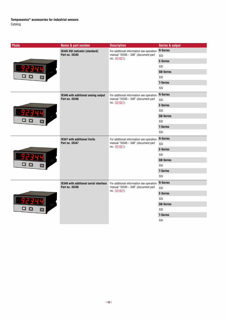
Temposonics® accessories for industrial sensorsCatalog
I 48 I
Photo Name & part number Description Series & output
IX345 SSI indicator (standard)Part no. IX345
For additional information see operation manual “IX345 – 348” (document part no.: 551621)
R-Series
SSI
E-Series
SSI
GB-Series
SSI
T-Series
SSI
IX346 with additional analog outputPart no. IX346
For additional information see operation manual “IX345 – 348” (document part no.: 551621)
R-Series
SSI
E-Series
SSI
GB-Series
SSI
T-Series
SSI
IX347 with additional limitsPart no. IX347
For additional information see operation manual “IX345 – 348” (document part no.: 551621)
R-Series
SSI
E-Series
SSI
GB-Series
SSI
T-Series
SSI
IX348 with additional serial interfacePart no. IX348
For additional information see operation manual “IX345 – 348” (document part no.: 551621)
R-Series
SSI
E-Series
SSI
GB-Series
SSI
T-Series
SSI

Temposonics® accessories for industrial sensorsCatalog
9. TempoLink smart assistant for R-Series V
DELIVERY
ORDER CODE
TempoLink smart assistant kit• TempoLink smart assistant• Power supply or cable for
insertion in existing sensor power supply with sensor mating connector and barrel connector
• Adapter cable to connect TempoLink smart assistant to R-Series V sensor
• USB cable for optional connection of TempoLink smart assistant to a computer
Adapter cables to connect TempoLink smart assistant to sensors of R-Series V can be ordered separately
1 2 3 4 5 6 7 8
T L 0 E M
a b c d
a Type
T L TempoLink smart assistant kit
b Power Supply
1 Plug-in power supply with plug adapters (AU, CCC, EU, UK, US)
2 Cable for insertion in existing sensor power supply with sensor mating connector and barrel connector
c Options
0 No options
d Adapter cable for connection to R-Series VE M 0 8 Cable with M8 female connetor (4 pin)
for connection type D56 (EtherNet/IP™) (part no. 254 887-1)
E M 1 2 Cable with M12 female connetor (4 pin) for connection type D58 (EtherNet/IP™ / Profinet) (part no. 254 897-1)
Plug-in power supply with plug adapters (AU, CCC, EU, UK, US)
OUTPUT INPUT
SENSOR 24V DC
Cable for insertion in existing sensor power supply with sensor mating connector and barrel connector
OUTPUT INPUT
SENSOR 24V DC
YOUR SMART ASSISTANTTempoLink smart assistant is an accessory of the R-Series V family of sensors. It supports setup of the sensor in the application as well as providing additional status information for diagnostics of the sensor.

UNITED STATESMTS Systems Corporation
Sensors Division
3001 Sheldon DriveCary, N.C. 27513Phone: +1 919 677-0100E-mail: [email protected]
GERMANYMTS Sensor Technologie
GmbH & Co. KG
Auf dem Schüffel 958513 LüdenscheidPhone: +49 2351 9587-0E-mail: [email protected]
ITALYBranch Offi ce
Phone: +39 030 988 3819E-mail: [email protected]
FRANCEBranch Offi ce
Phone: +33 1 58 4390-28E-mail: [email protected]
GREAT BRITAIN Branch Offi ce
Phone: +44 79 44 15 03 00E-mail: [email protected]
CHINABranch Offi ce
Phone: +86 21 6485 5800 E-mail: [email protected]
JAPANBranch Offi ce
Phone: +81 3 6416 1063E-mail: [email protected]
www.mtssensors.comMTS, Temposonics and Level Plus are registered trademarks of MTS Systems Corporation in the United States; MTS SENSORS and the MTS SENSORS logo are trademarks of MTS Systems Corporation within the United States. These trademarks may be protected in other countries. All other trademarks are the property of their respective owners. Copyright © 2018 MTS Systems Corporation. No license of any intellectual property rights is granted. MTS reserves the right to change the information within this document, change product designs, or withdraw products from availability for purchase without notice. Typographic and graphics errors or omissions are unintentional and subject to correction. Visit www.mtssensors.com for the latest product information.
Document Part Number: 551657 Revision F (EN) 08/2018