indoor unit pla-zm.ea series -...
TRANSCRIPT

Packaged Air ConditionersIndoor unit
PLA-ZM.EA Series
ISTRUZIONI DI FUNZIONAMENTOLeggere attentamente questi istruzioni di funzionamento prima di avviare l’unità, per un uso corretto e sicuro della stessa.
BEDIENUNGSHANDBUCHZum sicheren und einwandfreien Gebrauch der Klimaanlage dieses Bedienungshandbuch vor Inbetriebnahme gründlich durchlesen.
MANUEL D’UTILISATIONPour une utilisation correcte sans risques, veuillez lire le manuel d’utilisation en entier avant de vous servir du climatiseur.
OPERATION MANUALFor safe and correct use, please read this operation manual thoroughly before operating the air-conditioner unit.
BEDIENINGSHANDLEIDINGVoor een veilig en juist gebruik moet u deze bedieningshandleiding grondig doorlezen voordat u de airconditioner gebruikt.
MANUAL DE INSTRUCCIONESLea este manual de instrucciones hasta el final antes de poner en marcha la unidad de aire acondicionado para garantizar un uso seguro y correcto.
MANUAL DE OPERAÇÃOPara segurança e utilização correctas, leia atentamente o manual de operação antes de pôr a funcionar a unida-de de ar condicionado.
DRIFTSMANUALLæs venligst denne driftsmanual grundigt før airconditionanlægget betjenes af hensyn til sikker og korrekt brug.
DRIFTSMANUALLäs denna driftsmanual noga för säkert och korrekt bruk innan luftkonditioneringen används.
Français
Deutsch
English
Nederlands
Español
Italiano
Português
Dansk
Svenska
ΕΓΧΕΙΡΙΔΙΟ ΟΔΗΓΙΩΝ ΧΡΗΣΕΩΣΓια ασφάλεια και σωστή χρήση, παρακαλείστε διαβάσετε προσεχτικά αυτό το εγχειρίδιο χρήσεως πριν θέσετε σε λειτουργία τη μονάδα κλιματισμού.
Ελληνικά
Işletme ElkitabıEmniyetli ve doğru biçimde nasıl kullanılacağını öğrenmek için lütfen klima cihazını işletmeden önce bu elkitabını dikkatle okuyunuz.
Türkçe
BRUKSANVISNINGVennligst les nøye gjennom denne bruksanvisningen, for sikkert og riktig bruk av klimaanlegget.
INSTRUKCJA OBSŁUGIAby zapewnić bezpieczne i prawidłowe korzystanie z urządzenia, należy wcześniej uważnie przeczytać niniejszą instrukcję obsługi.
Norsk
Polski
PER L’UTENTE
VOOR DE GEBRUIKER
PARA EL USUARIO
FÜR BENUTZER
POUR L’UTILISATEUR
FÖR ANVÄNDAREN
TIL BRUGER
PARA O UTILIZADOR
ΓΙΑ ΤΟΝ ΧΡΗΣΤΗ
KULLANICI İÇİN
FOR BRUKER
INFORMACJA DLA UŻYTKOWNIKA
FOR USER
RG79F156H01_EN.indd 1 2016/12/13 9:04:30

2
This symbol mark is for EU countries only.This symbol mark is according to the directive 2012/19/EU Article 14 Information for users and Annex IX, and/or to the directive 2006/66/EC Article 20 Information for end-users and Annex II.Your MITSUBISHI ELECTRIC product is designed and manufactured with high quality materials and components which can be recycled and/or reused. This symbol means that electrical and electronic equipment, batteries and accumulators, at their end-of-life, should be disposed of separately from your household waste. If a chemical symbol is printed beneath the symbol (Fig. 1), this chemical symbol means that the battery or accumulator contains a heavy metal at a certain concentration. This will be indicated as follows: Hg: mercury (0.0005%), Cd: cadmium (0.002%), Pb: lead (0.004%) In the European Union there are separate collection systems for used electrical and electronic products, batteries and accumulators.Please, dispose of this equipment, batteries and accumulators correctly at your local community waste collection/recycling centre.Please, help us to conserve the environment we live in!
Contents
1. Safety Precautions . . . . . . . . . . . . . . . . . . . . . . . . . . . . . . . . . . . . . . . 22. Parts Names . . . . . . . . . . . . . . . . . . . . . . . . . . . . . . . . . . . . . . . . . . . . 33. Operation . . . . . . . . . . . . . . . . . . . . . . . . . . . . . . . . . . . . . . . . . . . . . . 74. Timer . . . . . . . . . . . . . . . . . . . . . . . . . . . . . . . . . . . . . . . . . . . . . . . . . 13
1. Safety Precautions
► Before installing the unit, make sure you read all the “Safety Precautions”. ► The “Safety Precautions” provide very important points regarding safety. Make sure you follow them. ► Please report to or take consent by the supply authority before connection to the system.
Symbols used in the text Warning:
Describes precautions that should be observed to prevent danger of in-jury or death to the user.
Caution:Describes precautions that should be observed to prevent damage to the unit.
Note
Fig.1
Warning:• There appliances are not accessible to the general public.• The unit must not be installed by the user. Ask the dealer or an au-
thorized company to install the unit. If the unit is installed improperly, water leakage, electric shock or fire may result.
• Do not stand on, or place any items on the unit. • Do not splash water over the unit and do not touch the unit with wet
hands. An electric shock may result. • Do not spray combustible gas close to the unit. Fire may result. • Do not place a gas heater or any other open-flame appliance where it
will be exposed to the air discharged from the unit. Incomplete com-bustion may result.
• Do not remove the front panel or the fan guard from the outdoor unit when it is running.
• When you notice exceptionally abnormal noise or vibration, stop op-eration, turn off the power switch, and contact your dealer.
• Never insert fingers, sticks etc. into the intakes or outlets. • If you detect odd smells, stop using the unit, turn off the power switch
and consult your dealer. Otherwise, a breakdown, electric shock or fire may result.
• This air conditioner is NOT intended for use by children or infirm per-sons without supervision.
• Young children must be supervised to ensure that they do not play with the air conditioner.
• If the refrigeration gas blows out or leaks, stop the operation of the air conditioner, thoroughly ventilate the room, and contact your dealer.
• This appliance is intended to be used by expert or trained users in shops, in light industry and on farms, or for commercial use by lay persons.
• This appliance can be used by children aged from 8 years and above and persons with reduced physical, sensory or mental capabilities or lack of experience and knowledge if they have been given supervision or instruction concerning use of the appliance in a safe way and under-stand the hazards involved. Children shall not play with the appliance. Cleaning and user maintenance shall not be made by children without supervision.
• This appliance is not intended for use by persons (including children) with reduced physical, sensory or mental capabilities, or lack of ex-perience and knowledge, unless they have been given supervision or instruction concerning use of the appliance by a person responsible for their safety.
• Children should be supervised to ensure that they do not play with the appliances.
• When installing or relocating, or servicing the air conditioner, use only the specified refrigerant written on outdoor unit to charge the refriger-ant lines. Do not mix it with any other refrigerant and do not allow air to remain in the lines.
If air is mixed with the refrigerant, then it can be the cause of abnormal high pressure in the refrigerant line, and may result in an explosion and other hazards.
The use of any refrigerant other than that specified for the system will cause mechanical failure or system malfunction or unit breakdown. In the worst case, this could lead to a serious impediment to securing product safety.
• This unit should be installed in rooms which exceed the floor space specified in outdoor unit installation manual.
Refer to outdoor unit installation manual.
5. Emergency Operation for Wireless Remote-controller . . . . . . . . . . . 146. Care and Cleaning. . . . . . . . . . . . . . . . . . . . . . . . . . . . . . . . . . . . . . . 147. Trouble Shooting . . . . . . . . . . . . . . . . . . . . . . . . . . . . . . . . . . . . . . . . 158. Specifications . . . . . . . . . . . . . . . . . . . . . . . . . . . . . . . . . . . . . . . . . . 17
Note:The phrase “Wired remote controller” in this operation manual refers only to the PAR-32MAA. If you need any information for the other remote controller, please refer to the instruction book included in this box.
Symbols used in the illustrations : Indicates a part which must be grounded.
MEANINGS OF SYMBOLS DISPLAYED ON THE UNITWARNING(Risk of fire)
This mark is for R32 refrigerant only. Refrigerant type is written on nameplate of outdoor unit.In case that refrigerant type is R32, this unit uses a flammable refrigerant.If refrigerant leaks and comes in contact with fire or heating part, it will create harmful gas and there is risk of fire.
Read the OPERATION MANUAL carefully before operation.
Service personnel are required to carefully read the OPERATION MANUAL and INSTALLATION MANUAL before operation.
Further information is available in the OPERATION MANUAL, INSTALLATION MANUAL, and the like.
RG79F156H01_EN.indd 2 2016/12/13 9:04:31

3
2. Parts Names
■ Indoor Unit PLA-ZM·EA
Fan steps 4 stepsVane Auto with swingLouver –Filter Long-lifeFilter cleaning indication 2,500 hrWireless remote controller model No. setting 001
Air outletFilter
Air intakeVane
Caution:• Do not use any sharp object to push the buttons, as this may damage
the remote controller. • Never block or cover the indoor or outdoor unit’s intakes or outlets.
Disposing of the unit When you need to dispose of the unit, consult your dealer.
■ Wired Remote Controller
Function buttons
4 3 2 1
5
6
7 8 9 0
The functions of the function buttons change depending on the screen.Refer to the button function guide that appears at the bottom of the LCD for the functions they serve on a given screen.When the system is centrally controlled, the button function guide that corresponds to the locked button will not appear.
Fri
Room
Set temp.
Mode Temp. Fan
Cool Auto
Main
Main display:Cursor Page
Main menuVane·Louver·Vent. (Lossnay)High powerTimerWeekly timerOU silent mode
Main display Main menu
Function guide
▌1 [ON/OFF] buttonPress to turn ON/OFF the indoor unit.
▌2 [SELECT] buttonPress to save the setting.
▌3 [RETURN] buttonPress to return to the previous screen.
▌4 [MENU] buttonPress to bring up the Main menu.
▌5 Backlit LCDOperation settings will appear.When the backlight is off, pressing any button turns the backlight on and it will stay lit for a certain period of time depending on the screen.
When the backlight is off, pressing any button turns the backlight on and does not perform its function. (except for the [ON/OFF] button)
▌6 ON/OFF lampThis lamp lights up in green while the unit is in operation. It blinks while the remote controller is starting up or when there is an error.
▌7 Function button [F1]Main display: Press to change the operation mode.Main menu: Press to move the cursor down.
▌8 Function button [F2]Main display: Press to decrease temperature.Main menu: Press to move the cursor up.
▌9 Function button [F3]Main display: Press to increase temperature.Main menu: Press to go to the previous page.
▌0 Function button [F4]Main display: Press to change the fan speed.Main menu: Press to go to the next page.
Controller interface
7 8 9 0 7 8 9 0
• Do not use means to accelerate the defrosting process or to clean, other than those recommended by the manufacturer.
• The appliance shall be stored in a room without continuously operat-ing ignition sources (for example: open flames, an operating gas appli-ance or an operating electric heater).
• Do not pierce or burn.• Be aware that refrigerants may not contain an odour.
1. Safety Precautions
RG79F156H01_EN.indd 3 2016/12/13 9:04:31

4
2. Parts Names
The main display can be displayed in two different modes: “Full” and “Basic”. The factory setting is “Full”. To switch to the “Basic” mode, change the setting on the Main display setting. (Refer to operation manual included with remote controller.)
▌1 Operation modeIndoor unit operation mode appears here.
▌2 Preset temperaturePreset temperature appears here.
▌3 Clock (See the Installation Manual.)Current time appears here.
▌4 Fan speedFan speed setting appears here.
▌5 Button function guideFunctions of the corresponding buttons appear here.
▌6 Appears when the ON/OFF operation is centrally controlled.
▌7 Appears when the operation mode is centrally controlled.
▌8 Appears when the preset temperature is centrally controlled.
▌9 Appears when the filter reset function is centrally controlled.
▌0 Indicates when filter needs maintenance.
▌1 Room temperature (See the Installation Manual.)Current room temperature appears here.
▌2 Appears when the buttons are locked.
<Full mode>* All icons are displayed for explanation.
Fri
Mode Temp. Fan
Room
Cool Set temp.
<Basic mode>
Fri
Cool
Mode Temp. Fan
Set temp.
4
3
2
1
5
6
78
90
1
3
)
4
!
7
@
23 45 6 8 9 2
1
5
▌3 Appears when the On/Off timer, Night setback, or Auto-off timer func-tion is enabled.
appears when the timer is disabled by the centralized control system.
▌4 Appears when the Weekly timer is enabled.
▌5 Appears while the units are operated in the energy-save mode. (Will not appear on some models of indoor units)
▌6 Appears while the outdoor units are operated in the silent mode.
▌7 Appears when the built-in thermistor on the remote controller is acti-vated to monitor the room temperature (1).
appears when the thermistor on the indoor unit is activated to monitor the room temperature.
▌8 Appears when the units are operated in the energy-save mode with 3D i-see Sensor.
▌9 Indicates the vane setting.
▌) Indicates the louver setting.
▌! Indicates the ventilation setting.
▌@ Appears when the preset temperature range is restricted.
Most settings (except ON/OFF, mode, fan speed, temperature) can be made from the Menu screen. (Refer to operation manual included with remote controller.)
Display
RG79F156H01_EN.indd 4 2016/12/13 9:04:32

5
2. Parts Names
■ Wireless Remote-Controller
Operation mode
Cool Dry
Fan Auto
Heat
Temperature settingThe units of temperature can be changed. For details, refer to the Installation Manual.
Not availableAppears when a non-supported func-tion is selected.
Battery replacement indicatorAppears when the remaining battery power is low.
Vane settingStep 1 Step 2 Step 3 Step 4 Step 5 Swing Auto
Fan speed settingAuto
3D i-see Sensor (Air distribution) Default Direct Indirect When Direct or Indirect
is selected, the vane setting is set to “Auto”.
Set Temperature buttons
Weekly timer ON/OFF button
Set Time button (Sets the time)
Airfl ow button (Changes up/down airfl ow direction)
Mode button (Changes operation mode)
Timer ON button
Timer OFF button
OFF/ON button
Fan Speed button (Changes fan speed)
SET/SEND button
CANCEL button
Up/Down buttons
Menu button
i-see button
Reset button
Remote controller display
Battery replacement indicator
Transmission area
Not available
RG79F156H01_EN.indd 5 2016/12/13 9:04:33

6
Battery installation/replacement
1. Remove the top cover, insert two LR6 AA batteries, and then install the top cover.
2. Press the Reset button.
1
2
3
Press the Reset button with an object that has a narrow end.
Top cover
Notes (Only for wireless remote controller):■ When using the wireless remote controller, point it towards the receiver on the indoor unit.■ If the remote controller is operated within approximately 2 minutes after power is supplied to the
indoor unit, the indoor unit may beep twice as the unit is performing the initial automatic check.■ The indoor unit beeps to confirm that the signal transmitted from the remote controller has been
received. Signals can be received up to approximately 7 meters in a direct line from the indoor unit in an area 45° to the left and right of the unit. However, illumination such as fluorescent lights and strong light can affect the ability of the indoor unit to receive signals.
■ If the operation lamp near the receiver on the indoor unit is blinking, the unit needs to be inspected. Consult your dealer for service.
■ Handle the remote controller carefully! Do not drop the remote controller or subject it to strong shocks. In addition, do not get the remote controller wet or leave it in a location with high humidity.
■ To avoid misplacing the remote controller, install the holder included with the remote controller on a wall and be sure to always place the remote controller in the holder after use.
■ If the indoor unit beeps 4 times when you are using the wireless remote controller, switch the auto mode setting to the AUTO (single set point) mode or AUTO (dual set point) mode.
For details, refer to the included Notice (A5 sheet) or the Installation Manual of wireless remote controller.
Two LR6 AA batteriesInsert the negative (–) end of each battery first. Install the batteries in the correct directions (+, –)!
■ Outdoor unit
Service Panel
Power
Ref. Pipes Indoor-Outdoor Connection wire
Earth
2. Parts Names
RG79F156H01_EN.indd 6 2016/12/13 9:04:33

7
3. Operation
■ About the operation method, refer to the operation manual that comes with each remote controller.
3.1. Turning ON/OFF[ON] [OFF]
Press the [ON/OFF] button.The ON/OFF lamp will light up in green, and the operation will start.
Press the [ON/OFF] button again.The ON/OFF lamp will come off, and the operation will stop.
■ Operation status memoryRemote controller setting
Operation mode Operation mode before the power was turned offPreset temperature Preset temperature before the power was turned offFan speed Fan speed before the power was turned off
■ Settable preset temperature rangeOperation mode Preset temperature rangeCool/Dry 19 – 30 ºCHeat 17 – 28 ºCAuto 19 – 28 ºC Fan/Ventilation Not settable
Note:Even if you press the ON/OFF button immediately after shutting down the operation is progress, the air conditioner will not start for about 3 minutes.This is to prevent the internal components from being damaged.
3.2. Mode SelectionPress the [F1] button to go through the op-eration modes in the order of “Cool”, “Dry”, “Fan”, “Auto”, and “Heat”. Select the desired operation mode.
Cool Dry Fan
Auto Heat
• Operation modes that are not available to the connected outdoor unit models will not appear on the display.
What the blinking mode icon meansThe mode icon will blink when other indoor units in the same refrigerant system (connected to the same outdoor unit) are already operated in a different mode. In this case, the rest of the unit in the same group can only be operated in the same mode.
Automatic operation <Single set point>■ According to a set temperature, cooling operation starts if the room tem-
perature is too hot and heating operation starts if the room temperature is too cold.
■ During automatic operation, if the room temperature changes and remains 2.0 °C or more above the set temperature for 15 minutes, the air condi-tioner switches to cool mode. In the same way, if the room temperature remains 2.0 °C or more below the set temperature for 15 minutes, the air conditioner switches to heat mode.
Cool mode 15 minutes (switches from heating to cooling)
Set temperature +2.0°C
Set temperature
Set temperature -2.0°C
15 minutes (switches from cooling to heating)
F1 F2 F3 F4
CoolRoom
AutoSet temp.
Mode Temp. Fan
Fri
<Dual set point>Note:• This function cannot be set depending on the outdoor unit to be
connected.When the operation mode is set to the Auto (dual set point) mode, two preset temperatures (one each for cooling and heating) can be set. De-pending on the room temperature, indoor unit will automatically operate in either the Cool or Heat mode and keep the room temperature within the preset range.For details on how to operate, refer to manual of remote controller.
RG79F156H01_EN.indd 7 2016/12/13 9:04:33

8
3.4. Fan speed setting
F1 F2 F3 F4
CoolRoom
Set temp.
Mode Temp. Fan
Fri
Press the [F4] button to go through the fan speeds in the following order.Auto
• The available fan speeds depend on the models of connected indoor units.
Notes: ● The number of available fan speeds depends on the type of unit
connected.● In the following cases, the actual fan speed generated by the unit
will differ from the speed shown the remote controller display. 1. While the display is in “STAND BY” or “DEFROST” states. 2. When the temperature of the heat exchanger is low in the heat-
ing mode. (e.g. immediately after heating operation starts) 3. In HEAT mode, when room temperature is higher than the tem-
perature setting. 4. In COOL mode, when room temperature is lower than the tem-
perature setting. 5. When the unit is in DRY mode.
3.5. Airflow direction setting3.5.1 Navigating through the Main menu<Accessing the Main menu>
F1 F2 F3 F4
Main
Main display:Cursor Page
Main menuVane·Louver·Vent. (Lossnay)High powerTimerWeekly timerOU silent mode
3. Operation
Press the [MENU] button.The Main menu will appear.
<Item selection>
F1 F2 F3 F4
Main
Main display:Cursor Page
Main menuVane·Louver·Vent. (Lossnay)High powerTimerWeekly timerOU silent mode
Cursor
<Navigating through the pages>
F1 F2 F3 F4
Main
Main display:Cursor Page
Main menuVane·Louver·Vent. (Lossnay)High powerTimerWeekly timerOU silent mode
page
<Saving the settings>
F1 F2 F3 F4
OU silent modeMon Tue Wed Thu Fri Sat Sun
Start Stop Silent -
Setting display:day
<Exiting the Main menu screen>
F1 F2 F3 F4
CoolRoom
Set temp.
Mode Temp. Fan
Fri
If no buttons are touched for 10 minutes, the screen will automatically return to the Main display. Any settings that have not been saved will be lost.
<Display of unsupported functions>
F1 F2 F3 F4
Title
Not availableUnsupported function
Return:
Press [F3] to go to the previous page.Press [F4] to go to the next page.
Select the desired item, and press the [SELECT] button.
The screen to set the selected item will appear.
Press the [RETURN] button to exit the Main menu and return to the Main display.
The message at left will appear if the user selects a function not supported by the corresponding indoor unit model.
Press [F1] to move the cursor down.Press [F2] to move the cursor up.
3.3. Temperature setting<Cool, Dry, Heat, and Auto>
CoolRoom28.5
AutoSet temp.
Mode Temp. Fan
Fri
28.5Example display
(Centigrade in 0.5-degree increments)F1 F2 F3 F4
CoolRoom
AutoSet temp.
Mode Temp. Fan
Fri
Press the [F2] button to decrease the preset temperature, and press the [F3] button to increase.• Refer to the table on page 7 for the settable temperature range for dif-
ferent operation modes.• Preset temperature range cannot be set for Fan/Ventilation operation.• Preset temperature will be displayed either in Centigrade in 0.5- or
1-degree increments, or in Fahrenheit, depending on the indoor unit model and the display mode setting on the remote controller.
RG79F156H01_EN.indd 8 2016/12/13 9:04:33

9
Outlet No. 2 Outlet No. 3
Outlet No. 1 Outlet No. 4
3. Operation
3.5.2 Vane·Vent. (Lossnay)<Accessing the menu>
F1 F2 F3 F4
Main
Main display:Cursor Page
Main menuVane·Louver·Vent. (Lossnay)High powerTimerWeekly timerOU silent mode
<Vane setting>
F1 F2 F3 F4
Fri
Swing Off
LouverVent.Vane
<Vent. setting>
F1 F2 F3 F4
Fri
Low
Vent.
<Returning to the Main menu>
F1 F2 F3 F4
Main
Main display:Cursor Page
Main menuVane·Louver·Vent. (Lossnay)High powerTimerWeekly timerOU silent mode
Select “Vane·Louver·Vent.(Lossnay)” from the Main menu (refer to page 8), and press the [SELECT] button.
Press the [F1] or [F2] button to go through the vane setting options: “Step 1”, “Step 2”, “Step 3”, “Step 4”, “Step 5”, “Swing” and “Auto”.Select the desired setting.
Swing
Auto
Select “Swing” to move the vanes up and down automatically.When set to “Step 1” through “Step 5”, the vane will be fixed at the selected angle.
Press the [F3] button to go through the ventilation setting options in the order of “Off”, “Low”, and “High”.* Settable only when LOSSNAY
unit is connected.Off Low High
Off Low High
• The fan on some models of indoor units may be interlocked with certain models of ventilation units.
Press the [RETURN] button to go back to the Main menu.
Remote controller settingThe airflow direction of this outlet is controlled by the airflow direc-tion setting of remote controller.
FixedThe airflow direction of this outlet is fixed in particular direction.* When it is cold because of direct
airflow, the airflow direction can be fixed horizontally to avoid direct airflow.
< How to set the fixed up/down air direction >For PLA-EA series, only the particular outlet can be fixed to certain direc-tion with the procedures below. Once fixed, only the set outlet is fixed every time air conditioner is turned on. (Other outlets follow UP/DOWN air direction setting of remote controller.)
Note: This function cannot be set depending on the outdoor unit to be connected.
■ Explanation of word• “Refrigerant address No.” and “Unit No.” are the numbers given to
each air conditioner.• “Outlet No.” is the number given to each outlet of air conditioner.
(Refer to the illustration below.)• “Up/Down air direction” is the direction (angle) to fix.
Step 1
Step 4
Auto
Step 2
Step 5
Step 3
Swing
Notes: ● During swing operation, the directional indication on the screen
does not change in sync with the directional vanes on the unit.● Available directions depend on the type of unit connected. ● In the following cases, the actual air direction will differ from the
direction indicated on the remote controller display. 1. While the display is in “STAND BY” or “DEFROST” states. 2. Immediately after starting heat mode (while the system is wait-
ing for the mode change to take effect). 3. In heat mode, when room temperature is higher than the tem-
perature setting.
Horizontal airflow
Note: The outlet No. is indicated by the number of grooves on both ends of each air outlet. Set the air direction while checking the information shown on the remote controller display.
Air outlet identification marks
RG79F156H01_EN.indd 9 2016/12/13 9:04:34
10
3. Operation
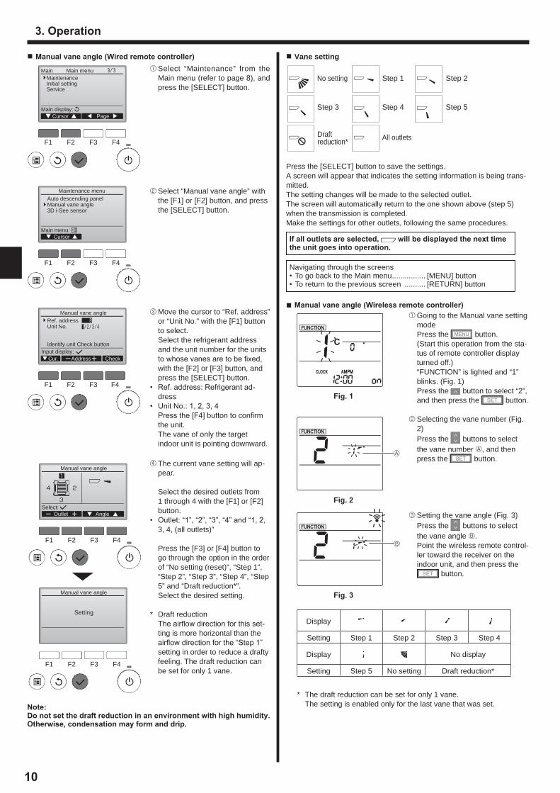
■ Manual vane angle (Wired remote controller)
F1 F2 F3 F4
Main
Main display:Cursor Page
Main menuMaintenanceInitial settingService
F1 F2 F3 F4
Maintenance menu
Main menu:Cursor
Auto descending panelManual vane angle3D i-See sensor
F1 F2 F3 F4
Manual vane angle
Input display:Cur. Address Check
Ref. addressUnit No.
Identify unit Check button
F1 F2 F3 F4
F1 F2 F3 F4
Manual vane angle
Manual vane angle
Select:
Setting
Outlet Angle
Note: Do not set the draft reduction in an environment with high humidity. Otherwise, condensation may form and drip.
1 Select “Maintenance” from the Main menu (refer to page 8), and press the [SELECT] button.
2 Select “Manual vane angle” with the [F1] or [F2] button, and press the [SELECT] button.
3 Move the cursor to “Ref. address” or “Unit No.” with the [F1] button to select.
Select the refrigerant address and the unit number for the units to whose vanes are to be fi xed, with the [F2] or [F3] button, and press the [SELECT] button.
• Ref. address: Refrigerant ad-dress
• Unit No.: 1, 2, 3, 4 Press the [F4] button to confi rm
the unit. The vane of only the target
indoor unit is pointing downward.
4 The current vane setting will ap-pear.
Select the desired outlets from 1 through 4 with the [F1] or [F2] button.
• Outlet: “1”, “2”, “3”, “4” and “1, 2, 3, 4, (all outlets)”
Press the [F3] or [F4] button to go through the option in the order of “No setting (reset)”, “Step 1”, “Step 2”, “Step 3”, “Step 4”, “Step 5” and “Draft reduction*”.
Select the desired setting.
* Draft reduction The airfl ow direction for this set-
ting is more horizontal than the airfl ow direction for the “Step 1” setting in order to reduce a drafty feeling. The draft reduction can be set for only 1 vane.
■ Vane setting
Press the [SELECT] button to save the settings.A screen will appear that indicates the setting information is being trans-mitted.The setting changes will be made to the selected outlet.The screen will automatically return to the one shown above (step 5) when the transmission is completed. Make the settings for other outlets, following the same procedures.
If all outlets are selected, will be displayed the next time the unit goes into operation.
Navigating through the screens• To go back to the Main menu ................ [MENU] button• To return to the previous screen .......... [RETURN] button
■ Manual vane angle (Wireless remote controller)
Fig. 1
A
Fig. 2
B
Fig. 3
Step 1 Step 2
Step 3
No setting
Draft reduction* All outlets
Step 5Step 4
1 Going to the Manual vane setting mode
Press the button. (Start this operation from the sta-
tus of remote controller display turned off.)
“FUNCTION” is lighted and “1” blinks. (Fig. 1)
Press the button to select “2”, and then press the button.
2 Selecting the vane number (Fig. 2)
Press the buttons to select the vane number A, and then press the button.
3 Setting the vane angle (Fig. 3) Press the buttons to select
the vane angle B. Point the wireless remote control-
ler toward the receiver on the indoor unit, and then press the
button.
Display
Setting Step 1 Step 2 Step 3 Step 4
Display No display
Setting Step 5 No setting Draft reduction*
* The draft reduction can be set for only 1 vane. The setting is enabled only for the last vane that was set.
RG79F156H01_EN.indd 10 2016/12/13 9:04:35

11
Vane settingDirect Indirect
Cooling horizontal → swing keep horizontalHeating keep downward downward → horizontal
F1 F2 F3 F4
3D i-See sensor
CursorSetting display:
Air distributionEnergy saving optionSeasonal airflow
3.6.2 Air distribution
F1 F2 F3 F4
Air distribution
Input display:Cur. Address Check
Ref. addressUnit No.
Identify unit Check button
F1 F2 F3 F4
Air distribution
Select:Cur.
Ref. addressUnit No.Auto vane
Direct/Indirect setting
All
Direct/Indirect
3 Select the desired menu with the [F1] or [F2] button, and press the [SELECT] button.
• Air distribution Select the airflow direction control
method when the airflow direction is set to “Auto”.
• Energy saving option Operates the energy-save mode
according to whether persons are detected in the room by the 3D i-see Sensor.
• Seasonal airflow When the thermostat turns off, the
fan and the vanes operate accord-ing to the control settings.
1 Move the cursor to “Ref. address” or “Unit No.” with the [F1] button to select.
Select the refrigerant address and the unit number for the units to whose vanes are to be fixed, with the [F2] or [F3] button, and press the [SELECT] button.
• Ref. address: Refrigerant address• Unit No.: 1, 2, 3, 4 Press the [F4] button to confirm
the unit. The vane of only the target indoor
unit is pointing downward.
2 Select the menu with the [F4] but-ton.
Default → Area → Direct/Indirect → Default…
Default: The vanes move the same as during normal operation.
“Area”*: The vanes move to the down airflow direction toward ar-eas with a high floor temperature during cooling mode and toward areas with a low floor temperature during heating mode. Otherwise, the vanes move to the horizontal airflow direction.
“Direct/Indirect”*: The vanes automatically move relative to the areas where persons are detect-ed.
The vanes operate as indicated in the following table.
* In order to enable this function, the airflow direction must be set to “Auto”.
3. Operation
1 First, confirm by setting “Ref. address” to 0 and “Unit No.” to 1.
• Move the cursor to “Ref. address” or “Unit No.” with the [F1] button to select.
• Select the refrigerant address and the unit number for the units to whose vanes are to be fixed, with the [F2] or [F3] button, and press the [SELECT] button.
• Ref. address: Refrigerant address• Unit No.: 1, 2, 3, 4 Press the [F4] button to confirm
the unit.
2 Change the “Unit No.” in order and check each unit.
• Press the [F1] button to select “Unit No.”.
Press the [F2] or [F3] button to change the “Unit No.” to the unit that you want to check, and then press the [F4] button.
• After pressing the [F4] button, wait approximately 15 seconds, and then check the current state of the air conditioner.
→ The vane is pointing downward. → This air conditioner is displayed on the remote controller.
→ All outlets are closed. → Press the [RETURN] button and continue the operation from the beginning.
→ The messages shown to the left are displayed. → The target device does not exist at this refrig-erant address.
• Press the [RETURN] button to return to the initial screen.
3 Change the “Ref. address” to the next number.
• Refer to step 1 to change the “Ref. address” and continue with the confirmation.
3.6. 3D i-see Sensor settingNote:This function cannot be set depending on the outdoor unit to be connected.
3.6.1 3D i-see Sensor setting
F1 F2 F3 F4
Manual vane angle
Input display:Cur. Address Check
Ref. addressUnit No.
Identify unit Check button
F1 F2 F3 F4
Main
Main display:Cursor Page
Main menuMaintenanceInitial settingService
F1 F2 F3 F4
Maintenance menu
Main menu:Cursor
Auto descending panelManual vane angle3D i-See sensor
■ Confirmation procedure (wired remote controller)
F1 F2 F3 F4
Manual vane angle
Return:
Ref. addressUnit No.
Function setting for unitwith vane fully open.
F1 F2 F3 F4
Manual vane angle
Return:
No communicationCheck Unit state.
1 Select “Maintenance” from the Main menu (refer to page 8), and press the [SELECT] button.
2 Select “3D i-See sensor” with the [F1] or [F2] button, and press the [SELECT] button.
RG79F156H01_EN.indd 11 2016/12/13 9:04:35

12
3. Operation
F1 F2 F3 F4
Direct/Indirect setting
: Direct : Indirect : Indirect : Direct
Select:Outlet Angle
■ i-see button (Wireless remote controller)
1 Each time is pressed during operation, the setting changes in the following order: OFF → Direct → Indirect.
Display
Setting OFF Direct Indirect
When the setting is changed from OFF to Direct or Indirect, the vane setting changes to "Auto". This setting is applied collectively to all of the vanes.
3 When Direct/Indirect is selected, set each air outlet.
Select the air outlet with the [F1] or [F2] button, and change the set-ting with the [F4] button.
After changing the settings for all of the air outlets, press the [SE-LECT] button to save the settings.
3.6.3 Energy saving option
F1 F2 F3 F4
Energy saving option
CursorSetting display:
No occupancy energy saveRoom occupancy energy saveNo occupancy Auto-OFF
1 Select the desired menu with the [F1] or [F2] button.
No occupancy energy save If there are no persons in the room
for 60 minutes or more, energy-saving operation equal to 2 °C is performed.
Room occupancy energy save If the occupancy rate decreases
to approximately 30% of the maximum occupancy rate, energy-saving operation equal to 1 °C is performed.
No occupancy Auto-OFF If there are no persons in the
room for the set amount of time (60–180 minutes), the operation is automatically stopped.
2 When No occupancy energy save or Room occupancy energy save is selected
Select the setting with the [F4] but-ton.
OFF → Cooling only → Heating only → Cooling/Heating → OFF…
After changing the setting, press the [SELECT] button to save the setting.
OFF: The function is disabled. Cooling only: The function is ena-
bled only during cooling mode. Heating only: The function is ena-
bled only during heating mode. Cooling/Heating: The function is
enabled during both cooling mode and heating mode.
3 When No occupancy Auto-OFF is selected
Set the time with the [F3] or [F4] button.
---: The setting is disabled (the op-eration will not stop automatically).
60–180: The time can be set in 10-minute increments.
4 The message at left will appear if the operation was stopped automatically by the No occupancy Auto-OFF setting.
F1 F2 F3 F4
Energy saving option
Select:
No occupancy energy save
Cooling/Heating
F1 F2 F3 F4
Energy saving option
Select:
Room occupancy energy save
Cooling/Heating
F1 F2 F3 F4
Energy saving option
Select:Time
No occupancy Auto-OFF
120 min.
F1 F2 F3 F4
18:47 Thu
Shut down byNo Occupancy Auto-OFF
31/Dec AM12:59
RG79F156H01_EN.indd 12 2016/12/13 9:04:36

13
■ Timer functions are different by each remote controller.■ For details on how to operate the remote controller, refer to the appropriate operation manual included with each remote controller.
Notes: Any person at the following places cannot be detected.● Along the wall on which the air conditioner is installed● Directly under the air conditioner● Where any obstacle, such as furniture, is between the person and
the air conditionerA person may not be detected in the following situations.● Room temperature is high.● A person wears heavy clothes and his/her skin is not exposed.● A heating element of which temperature changes signifi cantly is
present.● Some heat sources, such as a small child or pet, may not be
sensed.● A heat source does not move for a long time.The 3D i-see Sensor operates once approximately every 3 minutes to measure the fl oor temperature and detect persons in the room.● The intermittent operating sound is a normal sound produced
when the 3D i-see Sensor is moving.
3.7. VentilationFor LOSSNAY combination■ The following 2 patterns of operation is available.
• Run the ventilator together with indoor unit.• Run the ventilator independently.
Notes: (for wireless remote controller)● Running the ventilator independently is not available.● No indication on the remote controller.
3. Operation
1 Select the setting with the [F4] button.
OFF → Cooling only → Heating only → Cooling/Heating → OFF…
After changing the setting, press the [SELECT] button to save the setting.
OFF: The function is disabled. Cooling only: When the thermostat
turns off during cooling mode, the vanes move up and down.
Heating only: When the thermostat turns off during heating mode, the vanes move to the horizontal airfl ow direction to circulate the air.
Cooling/Heating: The function is enabled during both cooling mode and heating mode.
* In order to enable this function, the airfl ow direction must be set to “Auto”.
3.6.4 Seasonal airfl ow function
F1 F2 F3 F4
Seasonal airflow
Select:
Seasonal airflow
Cooling/Heating
B
A
D
C
Weekly schedule (Wireless remote controller)■ The weekly schedule can be set to four operation patterns for each day of the week. The settings include the
on and off times and the set temperature.
<Editing mode>1. Switching to the editing mode
1 Press the button when the unit is operating or stopped. blinks. (Fig. 1)
2. Selecting the setting pattern1 Press the button to select the setting pattern number. Each time the button is pressed, the pattern number A changes in the following order: 1 → 2 → 3 → 4.
3. Selecting the day of the week1 Press the button to select the day of the week to set. Each time the button is pressed, the day of the week B changes in the following order: Mon → Tue
→ Wed → Thu → Fri → Sat → Sun → All days.4. Selecting the operation settings
1 Push the button to select the operation on or off setting. (Fig. 2) ( ) is lighted. Each time the button is pressed, the setting changes in the following order: → .2 Press the button to select the operation time. (Fig. 3) The operation time blinks. Set the operation time using the buttons.• The operation time can be set in 10-minute increments.3 Push the button to select the set temperature. (Fig. 4) The set temperature blinks. Set the temperature using the buttons.• When setting the off operation, the temperature cannot be set. When the AUTO (dual set point) mode is enabled, press the button to switch between the upper limit
C and the lower limit D. (Fig. 5)4 By pressing the button, the pattern number settings for the displayed day of the week are deleted.5 Repeat steps 2–4 to select the settings for each day of the week.
<Transmitting the settings>
Point the transmission area of the wireless remote controller towards the receiver on the indoor unit and oper-ate the controller. Confi rm that the indoor unit beeps 7 times.
Press the button.
<Enabling the weekly schedule>Press the button.The weekly schedule operates when is on.• The weekly schedule does not function when the On/Off timer is enabled.The weekly schedule operates when all of the On/Off timer settings have been executed.
Fig. 2
Fig. 3
Fig. 4
Fig. 5
Fig. 1
4. Timer
RG79F156H01_EN.indd 13 2016/12/13 9:04:36

14
6. Care and Cleaning
■ Filter information■ Filter information
CoolRoom
AutoSet temp.
Mode Temp. Fan
Fri will appear on the Main display in the Full mode when it is time to clean the filters.
Wash, clean, or replace the filters when this sign appears.Refer to the indoor unit Instruc-tions Manual for details.
F1 F2 F3 F4
Main
Main display:Cursor Page
Main menuRestrictionEnergy savingNight setbackFilter informationError information
Select “Filter information” from the Main menu (refer to page 8), and press the [SELECT] button.
F1 F2 F3 F4
Main menu:
Filter information
Reset
Please clean the filter.Press Reset button afterfilter cleaning.
Press the [F4] button to reset filter sign.Refer to the indoor unit Instructions Manual for how to clean the filter.
F1 F2 F3 F4
Filter information
Filter information
OKCancel
Reset filter sign?
Filter sign reset
Main menu:
Select “OK” with the [F4] button.
A confirmation screen will appear.
Navigating through the screens• To go back to the Main menu ....................... [MENU] button• To return to the previous screen ....................... [RETURN] button
When the remote controller cannot be usedWhen the batteries of the remote controller run out or the remote controller malfunctions, the emergency operation can be done using the emergency buttons on the grille.
A DEFROST/STAND BY lampB Operation lampC Emergency operation cooling switchD Emergency operation heating switchE Receiver
Starting operation• To operate the cooling mode, press the button C for more than 2
seconds.• To operate the heating mode, press the button D for more than 2
seconds.• Lighting of the Operation lamp B means the start of operation.
Notes:● Details of emergency mode are as shown below.Details of EMERGENCY MODE are as shown below.
Operation mode COOL HEATSet temperature 24°C 24°C
Fan speed High HighAirflow direction Horizontal Downward
Stopping operation• To stop operation, press the button C or the button D for more than
2 seconds.
5. Emergency Operation for Wireless Remote-controller
E
C D
B A
RG79F156H01_EN.indd 14 2016/12/13 9:04:36

15
6. Care and Cleaning
CoolRoom
AutoSet temp.
Mode Temp. Fan
FriWhen the is displayed on the Main display in the Full mode, the system is centrally controlled and the filter sign cannot be reset.
If two or more indoor units are connected, filter cleaning timing for each unit may be different, depending on the filter type.The icon will appear when the filter on the main unit is due for cleaning. When the filter sign is reset, the cumulative operation time of all units will be reset.The icon is scheduled to appear after a certain duration of operation, based on the premise that the indoor units are installed in a space with ordinary air quality. Depending on the air quality, the filter may require more frequent cleaning.The cumulative time at which filter needs cleaning depends on the model.• This indication is not available for wireless remote controller.
7. Trouble Shooting
Having trouble? Here is the solution. (Unit is operating normally.)Air conditioner does not heat or cool well. ■ Clean the filter. (Airflow is reduced when the filter is dirty or clogged.)
■ Check the temperature adjustment and adjust the set temperature.■ Make sure that there is plenty of space around the outdoor unit. Is the
indoor unit air intake or outlet blocked?■ Has a door or window been left open?
When heating operation starts, warm air does not blow from the indoor unit soon.
■ Warm air does not blow until the indoor unit has sufficiently warmed up.
During heating mode, the air conditioner stops before the set room temperature is reached.
■ When the outdoor temperature is low and the humidity is high, frost may form on the outdoor unit. If this occurs, the outdoor unit performs a defrosting operation. Normal operation should begin after approxi-mately 10 minutes.
During cooling mode, the air conditioner stops when the set room tem-perature is reached.
■ For PLA-EA series, when the set room temperature is reached during cooling mode, the fan operates at the lowest speed.
Airflow direction changes during operation or airflow direction cannot be set.
■ During heating mode, the vanes automatically move to the horizontal airflow direction when the airflow temperature is low or during defrost-ing mode.
When the airflow direction is changed, the vanes always move up and down past the set position before finally stopping at the position.
■ When the airflow direction is changed, the vanes move to the set posi-tion after detecting the base position.
A flowing water sound or occasional hissing sound is heard. ■ These sounds can be heard when refrigerant is flowing in the air conditioner or when the refrigerant flow is changing.
A cracking or creaking sound is heard. ■ These sounds can be heard when parts rub against each due to expansion and contraction from temperature changes.
The room has an unpleasant odor. ■ The indoor unit draws in air that contains gases produced from the walls, carpeting, and furniture as well as odors trapped in clothing, and then blows this air back into the room.
A white mist or vapor is emitted from the indoor unit. ■ If the indoor temperature and the humidity are high, this condition may occur when operation starts.
■ During defrosting mode, cool airflow may blow down and appear like a mist.
Water or vapor is emitted from the outdoor unit. ■ During cooling mode, water may form and drip from the cool pipes and joints.
■ During heating mode, water may form and drip from the heat ex-changer.
■ During defrosting mode, water on the heat exchanger evaporates and water vapor may be emitted.
“ ” appears in the remote controller display. ■ During central control, “ ” appears in the remote controller display and air conditioner operation cannot be started or stopped using the remote controller.
Caution:• Ask authorized people to clean the filter.
■ Cleaning the filters• Clean the filters using a vacuum cleaner. If you do not have a vacuum
cleaner, tap the filters against a solid object to knock off dirt and dust.• If the filters are especially dirty, wash them in lukewarm water. Take care
to rinse off any detergent thoroughly and allow the filters to dry completely before putting them back into the unit.
Caution:• Do not dry the filters in direct sunlight or by using a heat source,
such as an electric heater: this may warp them.• Do not wash the filters in hot water (above 50°C), as this may
warp them.• Make sure that the air filters are always installed. Operating the
unit without air filters can cause malfunction.
Caution:• Before you start cleaning, stop operation and turn OFF the power
supply. • Indoor units are equipped with filters to remove the dust of sucked-
in air. Clean the filters using the methods shown in the following sketches.
RG79F156H01_EN.indd 15 2016/12/13 9:04:37

16
7. Trouble Shooting
Having trouble? Here is the solution. (Unit is operating normally.)When restarting the air conditioner soon after stopping it, it does not operate even though the ON/OFF button is pressed.
■ Wait approximately three minutes. (Operation has stopped to protect the air conditioner.)
Air conditioner operates without the ON/OFF button being pressed. ■ Is the on timer set? Press the ON/OFF button to stop operation.■ Is the air conditioner connected to a central remote controller? Consult the concerned people who control the air conditioner.■ Does “ ” appear in the remote controller display? Consult the concerned people who control the air conditioner.■ Has the auto recovery feature from power failures been set? Press the ON/OFF button to stop operation.
Air conditioner stops without the ON/OFF button being pressed. ■ Is the off timer set? Press the ON/OFF button to restart operation.■ Is the air conditioner connected to a central remote controller? Consult the concerned people who control the air conditioner.■ Does “ ” appear in the remote controller display? Consult the concerned people who control the air conditioner.
Remote controller timer operation cannot be set. ■ Are timer settings invalid? If the timer can be set, or appears in the remote controller
display.“PLEASE WAIT” appears in the remote controller display. ■ The initial settings are being performed. Wait approximately 3 min-
utes.An error code appears in the remote controller display. ■ The protection devices have operated to protect the air conditioner.
■ Do not attempt to repair this equipment by yourself. Turn off the power switch immediately and consult your dealer. Be
sure to provide the dealer with the model name and information that appeared in the remote controller display.
Draining water or motor rotation sound is heard. ■ When cooling operation stops, the drain pump operates and then stops. Wait approximately 5 minutes.
The vanes do not move or the indoor unit does not respond to input from the wireless remote controller.
■ The junction wire connectors of the vane motor and signal receiver may not be connected correctly. Have an installer check the connec-tions. (The colors of the male and female sections of the junction wire connectors must match.)
Noise is louder than specifications. ■ The indoor operation sound level is affected by the acoustics of the particular room as shown in the following table and will be higher than the noise specification, which was measured in anechoic room.
High sound absorbing rooms Normal rooms Low sound
absorbing rooms
Locationexamples
Broadcasting studio, music
room, etc.
Reception room, hotel lobby, etc.
Office, hotel room
Noise levels 3 to 7 dB 6 to 10 dB 9 to 13 dB
Nothing appears in the wireless remote controller display, the display is faint, or signals are not received by the indoor unit unless the remote controller is close.
■ The batteries are low. Replace the batteries and press the Reset button.■ If nothing appears even after the batteries are replaced, make sure
that the batteries are installed in the correct directions (+, –).The operation lamp near the receiver for the wireless remote controller on the indoor unit is blinking.
■ The self diagnosis function has operated to protect the air conditioner.■ Do not attempt to repair this equipment by yourself. Turn off the power switch immediately and consult your dealer. Be
sure to provide the dealer with the model name.
RG79F156H01_EN.indd 16 2016/12/13 9:04:37

17
8. Specifications
Model PLA-ZM35EA PLA-ZM50EA PLA-ZM60EA PLA-ZM71EA PLA-ZM100EA PLA-ZM125EA PLA-ZM140EAPower source∙ Voltage/Frequency <V / Hz> ~/N 230/50
Rated Input∙ Cooling/Heating indoor only <kW> 0.03/0.03 0.03/0.03 0.03/0.03 0.05/0.05 0.07/0.07 0.08/0.08 0.10/0.10
Rated Current∙ Cooling/Heating indoor only <A> 0.21/0.19 0.22/0.20 0.22/0.20 0.34/0.32 0.47/0.45 0.52/0.50 0.66/0.64
Heater <kW> – – – – – – –Height dimension <mm> 258 (40) 298 (40)Width dimension <mm> 840 (950)Depth dimension <mm> 840 (950)Fan airflow rate∙ Low-Middle2-Middle1-High <m3 / min> 11-13-15-16 12-14-16-18 12-14-16-18 17-19-21-23 19-22-25-28 21-24-26-29 24-26-29-32
Noise level (SPL)∙ Low-Middle2-Middle1-High <dB> 26-28-29-31 27-29-31-32 27-29-31-32 28-30-33-36 31-34-37-40 33-36-39-41 36-39-42-44
Net weight <kg> 21 (5) 24 (5) 26 (5)
*1. The figure in ( ) indicates standard Grille’s.
RG79F156H01_EN.indd 17 2016/12/13 9:04:37

Printed in UNITED KINGDOMRG79F156H01
HEAD OFFICE: TOKYO BUILDING, 2-7-3, MARUNOUCHI, CHIYODA-KU, TOKYO 100-8310, JAPAN
Please be sure to put the contact address/telephone number on this manual before handing it to the customer.
This product is designed and intended for use in the residential,commercial and light-industrial environment.
RG79F156H01_EN.indd 20 2016/12/13 9:04:37