indoor measurments
TRANSCRIPT
8/2/2019 Indoor Measurments
http://slidepdf.com/reader/full/indoor-measurments 1/5
Measurements for Distributed Antennas in WCDMA Indoor Network
Tero Isotalo, Jarno Niemelä and Jukka Lempiäinen
Institute of Communications Engineering, Tampere University of Technology
P.O.Box 553 FI-33101 TAMPERE FINLAND
Tel. +358 3 3115 5128, Fax +358 3 3115 3808
[email protected], http://www.cs.tut.fi/tlt/RNG/
Abstract— The target of the paper is to provide guidelinesfor indoor antenna selection for passive distributedantenna system or radiating cable implementation.Distributed antenna systems are commonly used forindoor installations, and radiating cables are often used intunnels, airplanes, or similar constricted areas. However,guidelines for optimizing WCDMA indoor networkantenna configuration are lacking in the literature. Inthis paper, the effect of different distributed antenna
configurations on signal quality and system performanceis studied, taking also radiating cable in comparison. Aspecial attention is paid to the future requirements of HSDPA. The measurement results show that planning of distributed antenna system is not very sensitive to theamount of antennas, as long as good coverage can beensured. Also radiating cable can be used, but providinggood coverage requires very dense installation of cables.
Key words: DAS, field measurements, indoor, radiating cable, WCDMA
1. Introduction
The need for macrocellular 3G (3rd generation) net-
works is fast increasing in densely built-up areas. In the
near future, a significant number of high data rate users
are located indoors. Therefore, providing good indoor
coverage and capacity also for indoor users will be an
important topic for network operators. Interference and
coverage limitations prevent efficient usage of outdoor
networks for serving indoor users. Thus, dedicated in-
door systems should be used [1]. Available solutions
for building indoor coverage with dedicated systems are
distributed antenna system (DAS), radiating cables (RC)
[2], or pico base stations [3].
Optimizing the behavior of basic UMTS (universal
mobile telecommunication system) indoor systems is an
up-to-date topic, but the future needs of implementing anHSDPA (high speed downlink packet access) function-
ality should be taken into account when planning new
indoor systems. To take a maximal advantage of the HS-
DPA enabled network, good radio conditions are needed
for high bit rate applications that in indoor emphasizes
the need of dedicated indoor systems [4]. In GSM
indoor system planning, the main target was to ensure
good coverage, whereas optimizing WCDMA (wideband
code division multiple access) indoor system might not
be that straightforward task. Indoor environment may
cause some challenges for WCDMA system due to,
e.g., lack of multipath diversity [5]. Thus, excluding few
simulation related references, e.g., [6], [7], guidelines for
a planning dedicated WCDMA indoor systems can not
be found from the literature.
2. WCDMA Indoor Planning
2.1. Indoor Environment
A system is considered to be a wideband, if the
signals’ transmission bandwidth is much wider than
the coherence bandwidth of the radio channel. The co-
herence bandwidth of macrocellular environment varies
typically between 0.053 MHz and 0.16 MHz, which
is clearly less than the bandwidth of WCDMA system
(3.84 MHz). Therefore, WCDMA system is rather robust
for frequency selective fast fading in typical outdoor
environments due to additional multipath diversity. How-
ever, in indoor environment the coherence bandwidth
can be more than 16 MHz. [5] This leads to WCDMA
signal being flat fading in most of typical indoor envi-
ronments, which might cause some unintended behavior
and lowered the system performance in indoor locations.2.2. Configuration Planning
Due to interference limited nature of WCDMA net-
works [8], the requirement of high throughput for a
single user in the cell edge or in an indoor location
can consume great amount of the downlink transmit
power of the whole cell that naturally affect the available
capacity of the whole cell. High bit rate users are rather
often in positions with high propagation loss, such as
buildings or cars. If outdoor network is not planned to
provide coverage and capacity for indoor users, or some
indoor location is introducing high load to some cells,
a dedicated indoor solution inside the building is worthconsidering for providing good indoor coverage [6], [9].
Different antenna configurations have been studied in
various cellular technologies, i.e., [10], [11]. Moreover,
simulations have been performed to analyze the capac-
ity of a dedicated WCDMA indoor system [6], [7].
However, measurement-based comparison of different
antenna configurations and radiating cable providing
background information and guidelines for planning an
indoor network can not be found in the literature.
There are some possible solutions for building indoor
coverage. Macro/microcellular networks can be planned
8/2/2019 Indoor Measurments
http://slidepdf.com/reader/full/indoor-measurments 2/5
in such a manner that in-building coverage is taken
into consideration, which reduces the need for deploying
dedicated indoor systems. However, the high in-building
penetration loss makes it an inefficient solution. Most
typical solution is implementation of independent in-
door base station, with either DAS, RC [12], or even
distributed base station system [4].The indoor environment constitutes a challenge for
radio network planning due to the difficulty to per-
form accurate simulations in indoor environment. In
macrocellular radio network planning, estimating the
propagation of the signal can be based on propagation
models, such as Okumura-Hata. In indoor, simple mod-
els can be used, for instance 3GPP path loss model
for indoor environment [13], but very high accuracies
should not be expected. On the other hand, ray-tracing
or similar accurate models can be exploited, but this
requires very detailed information on the building, which
may lead to higher planning cost. Practical knowledge
on earlier successful installations has been used in GSM
indoor planning, but a part of the phenomena caused by
WCDMA system remain currently undiscovered.
2.3. Indoor Antenna Systems
Distributed antenna system is the most common ap-
proach for providing in-building coverage. Antennas
used in DAS are small discrete antenna elements de-
signed specially for indoor use. Typically they are either
omnidirectional or low gain directional antennas. In a
passive DAS implementation1, signal is transferred from
base station by network of feeder cables, connected
by splitters and tappers. Advantages of DAS are easyplanning and good coverage, while drawbacks include
high installation costs compared to, e.g., indoor pico
cells or outdoor-to-indoor repeaters [14].
Radiating cable (RC), often also called as leaky
feeder, is simply a feeder cable with small holes or
groove in the outer conductor of coaxial cable, and the
signal leaks in a controlled way from the cable. The
end of a radiating cable needs to be either terminated,
or one can install a discrete antenna there. Radiating
cables are typically used in, e.g., tunnel installations.
Due to small EIRP (effective isotropic radiated power)
of RC, it is also a good choice for interference sensitive
environments, such as hospitals and airplanes.
Another possible approach for indoor building an
indoor systems is usage of pico cells; a single pico cell
or a dense enough network of small base stations with,
e.g., in-built omnidirectional antenna in desired area for
indoor coverage.
1Note that the fundamental difference between a passive and anactive DAS is the losses in the feeder lines. However, from antennaconfiguration point of view, this separation cannot be made if coveragetargets can be achieved. Hence, the results of this paper can be appliedto both distributed antenna systems.
3. Measured Quality Indicators
Coverage of a cell is estimated by P-CPICH RSCP
(received signal code power for the primary common pi-
lot channel). Standard deviation (STD) of RSCP caused
by free space attenuation together with slow and fast
fading indicates the smoothness of RSCP in the network.
Large variations in RSCP leads to greater slow fading
margins. Quality of the coverage is indicated by P-
CPICH E c/N 0, the received energy per chip on P-
CPICH divided by the power density in the band. The
P-CPICH E c/N 0 is defined as ratio between RSCP and
RSSI (received signal strength indicator):
E cN 0
=RSCP
RSSI (1)
In addition, interference level is indicated with signal
to interference ratio (SIR) for the P-CPICH:
SIR = SF 256 P P −CPICH
(1− α)P TOT + (I inter + pn)L(2)
where SF 256 is the processing gain for P-CPICH,
P P −CPICH is the transmit power of P-CPICH, α is
the downlink orthogonality factor, P TOT is the total
transmit power of the base station, I inter is the received
inter-cell interference, pn is the received noise power,
and L is the path loss. The instantaneous root mean
square (RMS) delay spread σRMS is evaluated in this
paper from scanner measurement according to following
definition:
σRMS =�
τ 2− τ
2 (3)
where
τ 2 =
ka2kτ 2
k
a2k
(4)
is the mean excess delay and
τ 2 =
ka2kτ k
a2k
(5)
is the mean delay with ak as the amplitude of k th
multipath component and its’ a relative delay of τ k.
4. Measurement Setup
Measurements were conducted in an university build-
ing, in two different environments; open area and of-
fice corridor. Open area environment consisted of an
open 100 m long large corridor, having an open hall
in the other end and being 2 floors in height. The
antennas were located in the 2nd floor level, whereas
the measurements were carried out in the 1st floor level.
Antennas did not have LOS (line-of-sight) between each
others, where as connection between antenna and UE
consisted of a mixture of LOS and NLOS (non-line-
of-sight) connections. The office corridor measurements
8/2/2019 Indoor Measurments
http://slidepdf.com/reader/full/indoor-measurments 3/5
2 dBi
EIRP
17.66dBm
CPICH
30dBm
RNC BTS
CPICH
30dBm
RNC BTS
-3 dB
CPICH
30dBm
RNC BTS
-5 dB
CPICH
30dBm
RNC
BTS
-3 dB
-3 dB
-3 dB
60 m
-10.12dB
25 m
-4.22dB
a) 1-Antenna
CPICH
30dBm
RNC
BTS
20m 2.66dB
b) 2-Antenna
c) 3-Antenna
d) 4-Antenna
e) Radiating
Cable
2 dBi
EIRP
14.66dBm
2 dBi
EIRP
12.66dBm
2 dBi
EIRP
11.66dBm
60 m
-10.12dB
60 m
-10.12dB
60 m
-10.12dB
60 m
-10.12dB
25 m
-4.22dB
25 m
-4.22dB
25 m
-4.22dB
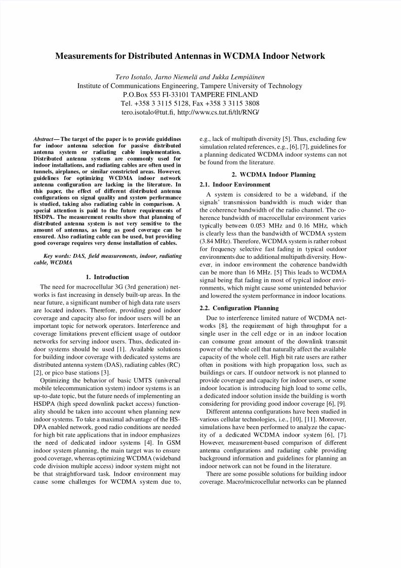
Figure 1. System block diagram and antenna configuration scenariosfor open area measurements.
were carried out in a narrow corridor opening to other
corridors, and having various small rooms along. An-
tennas were located in the 2nd floor, and measurements
were conducted in the 1st as well as in the 2nd floor.
Antennas had LOS between each others. Measurement
route in the 2nd floor had almost continuous LOS for
the antennas, whereas measurement route in the 1st floor
had only NLOS connections.
The measurements were carried out in an experimen-
tal WCDMA network, consisting of an RNC/Iub (radio
network controller) simulator running on a PC, and a
commercial WCDMA base station, connected to the
an antenna system. The antenna system consisted of a
feeder cable connected to varying antenna configuration.
The antenna configuration for open area measurements
is shown in Fig. 1, and the configuration for office
corridor measurements is otherwise similar, except the
attenuation in feeder cable is 2.9 dB smaller. Also a 4-
antenna scenario was excluded from measurements in
office corridor.
Depending on the antenna configuration, the signal
was transmitted either directly to an antenna or a RC,or split into 2-4 equal parts (2-3 for office corridor).
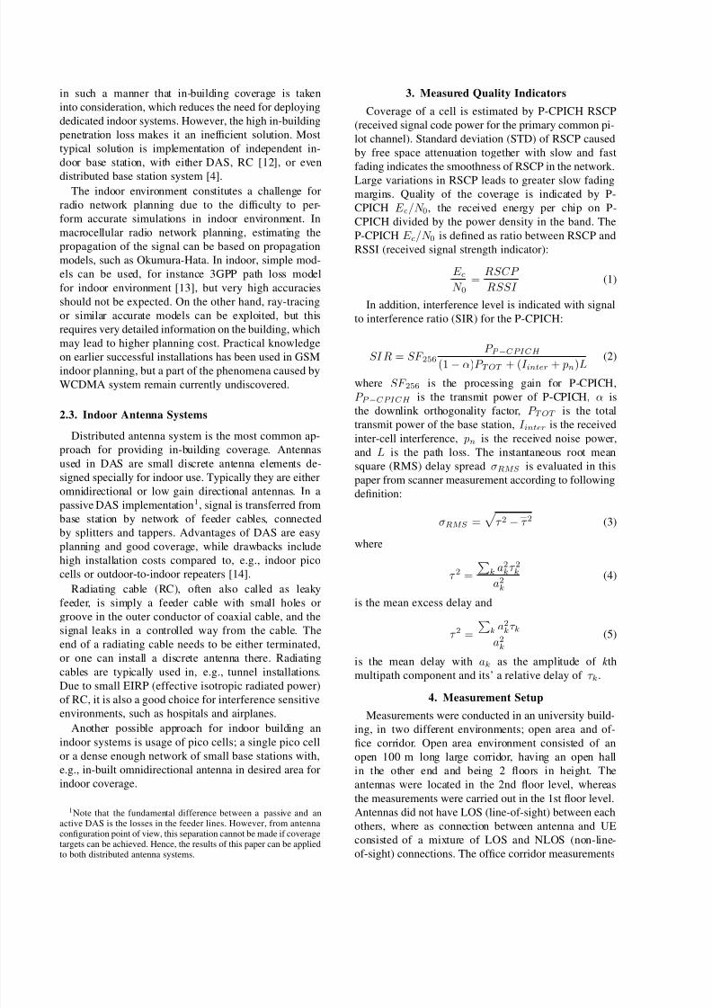
Antenna locations are shown in Fig. 2. (a)-(d). Antenna
locations for the office corridor are shown in blue/upper
markings, and for the open area with red/lower mark-
ings. Antennas used for the measurements were omni-
directional indoor antennas with 2 dBi gain. Radiating
cable and feeder cable were 1/2" coaxial cables, and the
length of the radiating cable was 20 m.
Measurement routes are shown in Fig. 2.(e) for the 1st
floor, and Fig. 2.(f) for the 2nd floor. The shorter mea-
surement routes in Fig. 2.(f) are measured underneath
(a) 1-antenna / RC (b) 2-antenna
(d) 4-antenna(c) 3-antenna
(e) Measurement routes, 1st floor (f) Measurement routes, 2nd floor
1<RC
RC 1<
2 2
2 2
4 4 4 4
3 3 3
3 3 3
Figure 2. Antenna positions for 1-4 -antenna and radiating cablescenarios (a)-(d), and measurement routes (e-f). (a)-(d) are locatedon the 2nd floor. Upper/blue markings are for the office corridor andlower/red for the open area.
the radiating cable.
Measurement equipment consisted of a WCDMA UE
and a WCDMA scanner, connected to a radio interface
measurement software. The cell scenario was isolated,
i.e., no inter-cell interference was present and the mea-
surements were conducted in connected mode having a
12.2 kbps speech connection. The measurement routes
were repeated several times in order to increase thereliability of results.
5. Measurement Results
All measured values are are shown in Table 1. For
the open area measurements, E c/N 0 values remain at
the level of −4 dB for all configurations, and moreover
the values are at the same level for all the antenna
configuration. This is natural when the load of the
network is low, and no coverage limitations occur,
i.e., RSCP remains at good level above the thermal
noise floor at the mobile. The RSCP level is improved
when increasing the amount of antennas. However, the
coverage improvement achieved by adding more thantwo antennas is rather small partly due to lower EIRP
(1 dB improvement of having four antennas instead of
two). However, with radiating cable the average RSCP is
clearly lower (13..17 dB difference compared to discrete
antennas). A decrease in STD of the level of RSCP was
expected after increasing the number of antennas, but it
remains almost unchanged in open area environment in
all discrete antenna scenarios. Radiating cable provides
clearly the smallest deviation in RSCP. The average
delay spread in discrete antenna scenarios is between
0.30 µs and 0.33 µs, whereas with radiating cable
8/2/2019 Indoor Measurments
http://slidepdf.com/reader/full/indoor-measurments 4/5
Table 1. Idle mode measurement results.Open area 1-antenna 2-antenna 3-antenna 4-antenna RC
E c/N 0 [dB] -4.07 -4.03 -4.14 -4.11 -4.10RSCP [dBm] -60.04 -57.50 -57.43 -56.47 -73.50RSCP STD [dB] 5.93 5.24 5.94 5.67 3.66Delay spread [µs] 0.33 0.30 0.33 0.33 0.39SIR [dB] 21.84 21.93 21.63 22.28 22.01
Office corridor, 2nd floor 1-antenna 2-antenna 3-antenna RC
E c/N 0 [dB] -4.12 -4.10 -4.05 -4.01RSCP [dBm] -45.44 -44.05 -41.74 -67.59RSCP STD [dB] 6.98 6.18 5.34 3.97Delay spread [µs] 0.31 0.29 0.28 0.34SIR [dB] 22.27 21.26 21.40 22.14
Office corridor, 1st floor 1-antenna 2-antenna 3-antenna RC
E c/N 0 [dB] -4.21 -4.12 -4.14 -4.49RSCP [dBm] -69.14 -68.49 -67.27 -90.98RSCP STD [dB] 8.11 5.00 4.39 7.47Delay spread [µs] 0.32 0.30 0.31 0.38SIR [dB] 21.74 21.79 22.79 20.83
17 18 19 20 21 22 23 24 250
0.1
0.2
0.3
0.4
0.5
0.6
0.7
0.8
0.9
1
F ( X )
CDF
1−antenna
2−antenna
3−
antenna4−antenna
RC
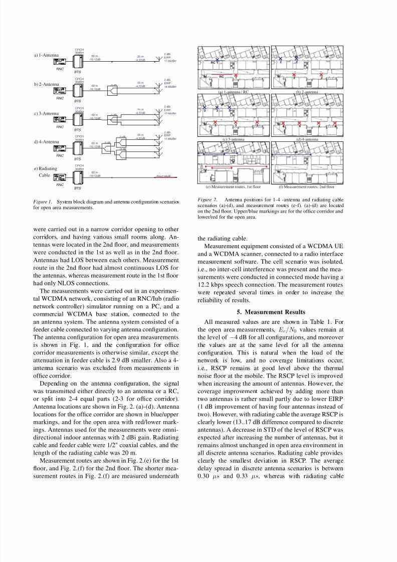
Figure 3. CDF of downlink SIR measurements in open area for allantenna configurations.
slightly higher, 0.39 µs. The results indicate that certain
amount of multipath diversity would be available in
the particular measurement scenario. Also SIR values
remain at the level of 22 dB. The CDF (cumulative
distribution function) of SIR in open area is shown
in Fig. 3. Increasing the amount of antennas is not
affecting SIR, since the variations between different
antenna configurations are inside one decibel.
In the office corridor in the 2nd floor, the mea-surements were conducted close to antennas with LOS
conditions. Again, E c/N 0 remains close to −4 dB due
to same reasons mentioned before and the level of RSCP
is again increasing when adding more antennas. There
is an improvement of 1.4 dB when adding a second an-
tenna, and another 2.3 dB when adding a third antenna.
Radiating cable has again clearly the worst average
RSCP. In the office corridor, STD of RSCP is behaving
expectedly, decreasing while increasing the number of
antennas and again, radiating cable provides the smallest
signal level variations. Also the delay spread values
17 18 19 20 21 22 23 24 250
0.1
0.2
0.3
0.4
0.5
0.6
0.7
0.8
0.9
1
F ( X )
CDF
1−antenna
2−antenna
3−
antennaRC
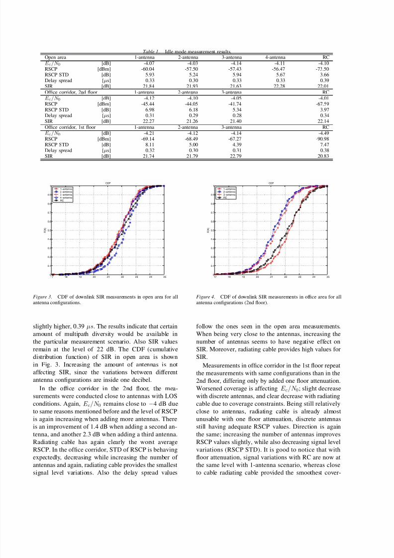
Figure 4. CDF of downlink SIR measurements in office area for allantenna configurations (2nd floor).
follow the ones seen in the open area measurements.
When being very close to the antennas, increasing the
number of antennas seems to have negative effect on
SIR. Moreover, radiating cable provides high values for
SIR.
Measurements in office corridor in the 1st floor repeat
the measurements with same configurations than in the
2nd floor, differing only by added one floor attenuation.
Worsened coverage is affecting E c/N 0; slight decreasewith discrete antennas, and clear decrease with radiating
cable due to coverage constraints. Being still relatively
close to antennas, radiating cable is already almost
unusable with one floor attenuation, discrete antennas
still having adequate RSCP values. Direction is again
the same; increasing the number of antennas improves
RSCP values slightly, while also decreasing signal level
variations (RSCP STD). It is good to notice that with
floor attenuation, signal variations with RC are now at
the same level with 1-antenna scenario, whereas close
to cable radiating cable provided the smoothest cover-
8/2/2019 Indoor Measurments
http://slidepdf.com/reader/full/indoor-measurments 5/5
14 16 18 20 22 24 260
0.1
0.2
0.3
0.4
0.5
0.6
0.7
0.8
0.9
1
F ( X
)
CDF
1−antenna
2−antenna
3−antenna
RC
Figure 5. CDF of downlink SIR measurements in office area for allantenna configurations (1st floor).
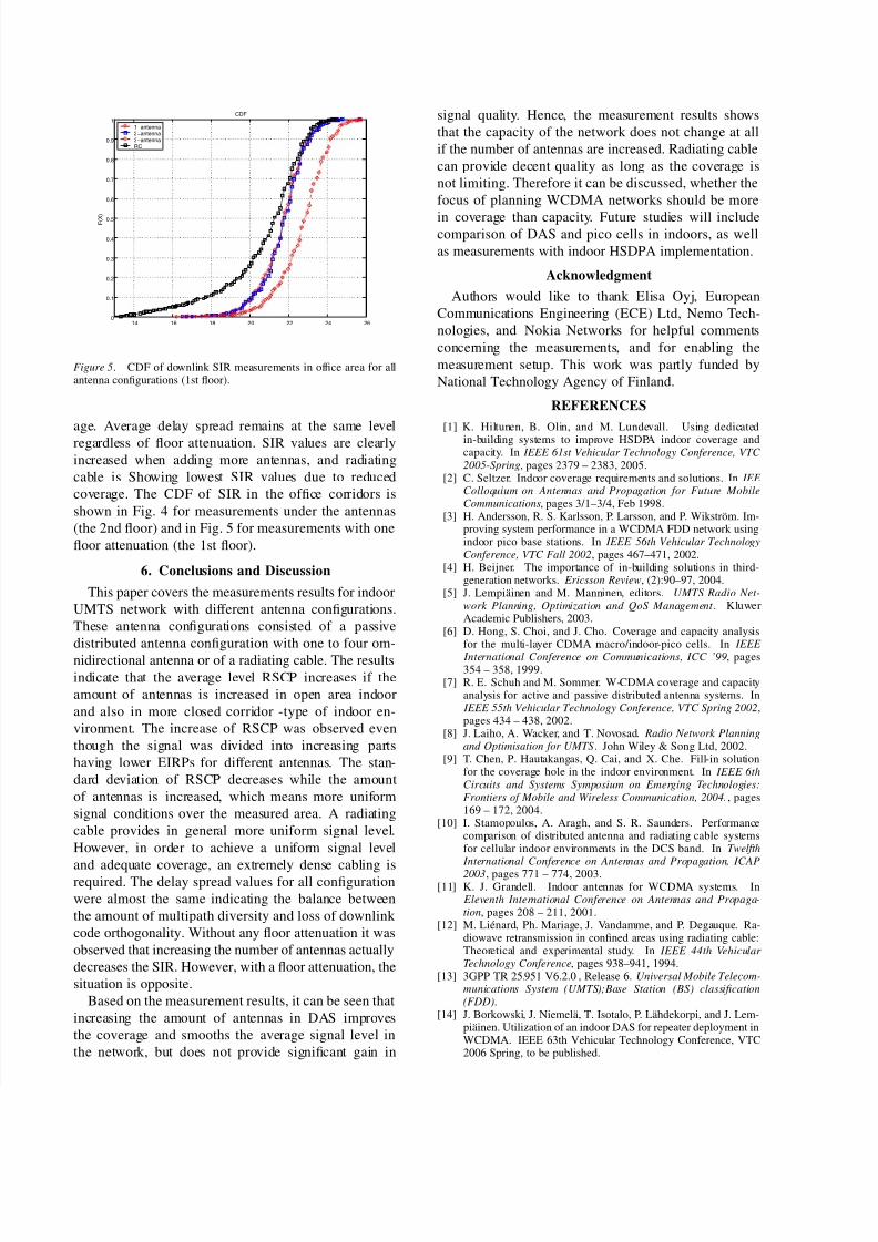
age. Average delay spread remains at the same level
regardless of floor attenuation. SIR values are clearly
increased when adding more antennas, and radiating
cable is Showing lowest SIR values due to reduced
coverage. The CDF of SIR in the office corridors is
shown in Fig. 4 for measurements under the antennas
(the 2nd floor) and in Fig. 5 for measurements with one
floor attenuation (the 1st floor).
6. Conclusions and Discussion
This paper covers the measurements results for indoor
UMTS network with different antenna configurations.
These antenna configurations consisted of a passive
distributed antenna configuration with one to four om-
nidirectional antenna or of a radiating cable. The results
indicate that the average level RSCP increases if the
amount of antennas is increased in open area indoor
and also in more closed corridor -type of indoor en-
vironment. The increase of RSCP was observed even
though the signal was divided into increasing parts
having lower EIRPs for different antennas. The stan-
dard deviation of RSCP decreases while the amount
of antennas is increased, which means more uniform
signal conditions over the measured area. A radiating
cable provides in general more uniform signal level.
However, in order to achieve a uniform signal level
and adequate coverage, an extremely dense cabling isrequired. The delay spread values for all configuration
were almost the same indicating the balance between
the amount of multipath diversity and loss of downlink
code orthogonality. Without any floor attenuation it was
observed that increasing the number of antennas actually
decreases the SIR. However, with a floor attenuation, the
situation is opposite.
Based on the measurement results, it can be seen that
increasing the amount of antennas in DAS improves
the coverage and smooths the average signal level in
the network, but does not provide significant gain in
signal quality. Hence, the measurement results shows
that the capacity of the network does not change at all
if the number of antennas are increased. Radiating cable
can provide decent quality as long as the coverage is
not limiting. Therefore it can be discussed, whether the
focus of planning WCDMA networks should be more
in coverage than capacity. Future studies will includecomparison of DAS and pico cells in indoors, as well
as measurements with indoor HSDPA implementation.
Acknowledgment
Authors would like to thank Elisa Oyj, European
Communications Engineering (ECE) Ltd, Nemo Tech-
nologies, and Nokia Networks for helpful comments
concerning the measurements, and for enabling the
measurement setup. This work was partly funded by
National Technology Agency of Finland.
REFERENCES
[1] K. Hiltunen, B. Olin, and M. Lundevall. Using dedicatedin-building systems to improve HSDPA indoor coverage andcapacity. In IEEE 61st Vehicular Technology Conference, VTC 2005-Spring, pages 2379 – 2383, 2005.
[2] C. Seltzer. Indoor coverage requirements and solutions. In IEE Colloquium on Antennas and Propagation for Future MobileCommunications, pages 3/1–3/4, Feb 1998.
[3] H. Andersson, R. S. Karlsson, P. Larsson, and P. Wikström. Im-proving system performance in a WCDMA FDD network usingindoor pico base stations. In IEEE 56th Vehicular TechnologyConference, VTC Fall 2002, pages 467–471, 2002.
[4] H. Beijner. The importance of in-building solutions in third-generation networks. Ericsson Review, (2):90–97, 2004.
[5] J. Lempiäinen and M. Manninen, editors. UMTS Radio Net-
work Planning, Optimization and QoS Management . KluwerAcademic Publishers, 2003.
[6] D. Hong, S. Choi, and J. Cho. Coverage and capacity analysisfor the multi-layer CDMA macro/indoor-pico cells. In IEEE
International Conference on Communications, ICC ’99, pages354 – 358, 1999.
[7] R. E. Schuh and M. Sommer. W-CDMA coverage and capacityanalysis for active and passive distributed antenna systems. In
IEEE 55th Vehicular Technology Conference, VTC Spring 2002,pages 434 – 438, 2002.
[8] J. Laiho, A. Wacker, and T. Novosad. Radio Network Planningand Optimisation for UMTS. John Wiley & Song Ltd, 2002.
[9] T. Chen, P. Hautakangas, Q. Cai, and X. Che. Fill-in solutionfor the coverage hole in the indoor environment. In IEEE 6thCircuits and Systems Symposium on Emerging Technologies:Frontiers of Mobile and Wireless Communication, 2004., pages169 – 172, 2004.
[10] I. Stamopoulos, A. Aragh, and S. R. Saunders. Performancecomparison of distributed antenna and radiating cable systemsfor cellular indoor environments in the DCS band. In Twelfth
International Conference on Antennas and Propagation, ICAP
2003, pages 771 – 774, 2003.[11] K. J. Grandell. Indoor antennas for WCDMA systems. In
Eleventh International Conference on Antennas and Propaga-tion, pages 208 – 211, 2001.
[12] M. Liénard, Ph. Mariage, J. Vandamme, and P. Degauque. Ra-diowave retransmission in confined areas using radiating cable:Theoretical and experimental study. In IEEE 44th Vehicular Technology Conference, pages 938–941, 1994.
[13] 3GPP TR 25.951 V6.2.0 , Release 6. Universal Mobile Telecom-munications System (UMTS);Base Station (BS) classification(FDD).
[14] J. Borkowski, J. Niemelä, T. Isotalo, P. Lähdekorpi, and J. Lem-piäinen. Utilization of an indoor DAS for repeater deployment inWCDMA. IEEE 63th Vehicular Technology Conference, VTC2006 Spring, to be published.