introductioninsitutest.com.au/wp-content/uploads/ic tech brief...the basis of the sakai ic system is...
TRANSCRIPT
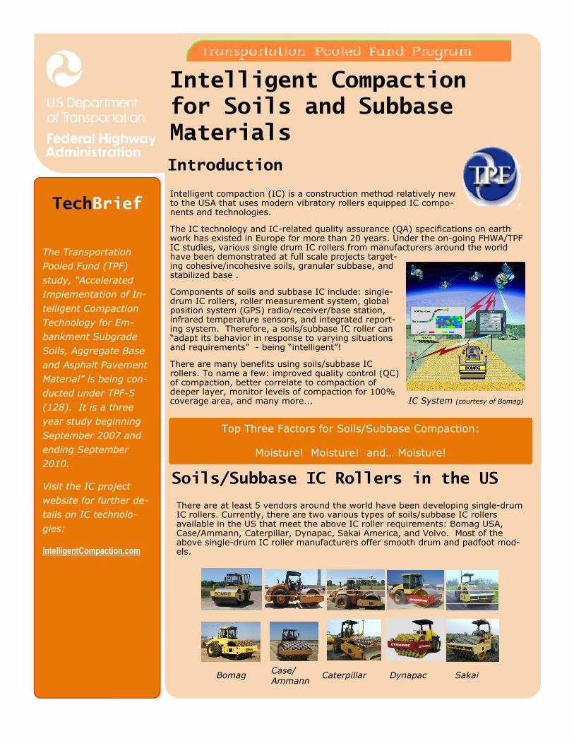
Intelligent compaction (IC) is a construction method relatively new to the USA that uses modern vibratory rollers equipped IC compo-nents and technologies.
The IC technology and IC-related quality assurance (QA) specifications on earth work has existed in Europe for more than 20 years. Under the on-going FHWA/TPF IC studies, various single drum IC rollers from manufacturers around the world have been demonstrated at full scale projects target-ing cohesive/incohesive soils, granular subbase, and stabilized base .
Components of soils and subbase IC include: single-drum IC rollers, roller measurement system, global position system (GPS) radio/receiver/base station, infrared temperature sensors, and integrated report-ing system. Therefore, a soils/subbase IC roller can “adapt its behavior in response to varying situations and requirements” - being “intelligent”!
There are many benefits using soils/subbase IC rollers. To name a few: improved quality control (QC) of compaction, better correlate to compaction of deeper layer, monitor levels of compaction for 100% coverage area, and many more...
Introduction
Soils/Subbase IC Rollers in the US
There are at least 5 vendors around the world have been developing single-drum IC rollers. Currently, there are two various types of soils/subbase IC rollers available in the US that meet the above IC roller requirements: Bomag USA, Case/Ammann, Caterpillar, Dynapac, Sakai America, and Volvo. Most of the above single-drum IC roller manufacturers offer smooth drum and padfoot mod-els.
Intelligent Compaction for Soils and Subbase Materials
The Transportation
Pooled Fund (TPF)
study, “Accelerated
Implementation of In-
telligent Compaction
Technology for Em-
bankment Subgrade
Soils, Aggregate Base
and Asphalt Pavement
Material” is being con-
ducted under TPF-5
(128). It is a three
year study beginning
September 2007 and
ending September
2010.
Visit the IC project
website for further de-
tails on IC technolo-
gies:
IntelligentCompaction.com
TechBrief
Bomag
IC System (courtesy of Bomag)
Top Three Factors for Soils/Subbase Compaction:
Moisture! Moisture! and… Moisture!
Case/ Ammann
Caterpillar Dynapac Sakai

The basis of the Sakai IC system is the IC roller (equipped with CCV measurement system, temperature sensors, and GPS radio/receiver) and a GPS with radio base station. All measurements are consoli-dated to the CIS display. IC data can then be transferred to PCs via USB ports for further reporting/documentation and integration with CAD systems.
The Sakai Compaction control value (CCV) is a unitless vibratory-based technology which makes use of an accelerometer mounted to the roller drum to create a record of machine-ground interaction. Its value represents the stiffness of the compacted pavement layers underneath. The concept behind the CCV is that as the ground stiffness increases, the roller drum starts to enter into a “jumping” motion which results in vibration accelerations at various frequency components. The current Sakai IC system does not yet consist of auto-feedback.
Sakai Soil IC System
The Bomag IC system is called VarioControl IC system. The Bomag IC roller is equipped with two acceleration transducers, processor/control unit, distance measurement, GPS ra-dio/antenna, Bomag Operation Panel (BOP), and onboard BCM 05 documentation system (BCM 05-Tablet-PC, BCM 05 mobile software). This system is capable of measuring compac-tion values that can be transferred to another computer using USB memory sticks for further analysis and reporting using the BCM05 office software.
The Bomag IC measurement value is called Evib [MN/m2] or vibration modulus (more strictly, stiffness). The Evib values are computed based on the compression paths of contact forces vs. drum displacement curves. The Evib values increase with increasing pass number. Evib also responds to changes of material density and asphalt mixture temperature (with dropping compaction temperature, Evib of asphalt mix-tures becomes greater). The Bomag Evib values correlate well with load bearing capacities (Ev1/Ev2) from the plate loading tests. The feedback control in the Bomag IC system is called VarioControl that enables the automatic adaption of the amplitude during the compaction process.
Bomag Soil IC System
Page 2 INTELLIGENT COMPACTION FOR SOILS AND SUBBASE MATERIALS
Sakai IC system
Bomag BCM05 System
US DEPARTMENT OF TRANSPORTATION Page 3
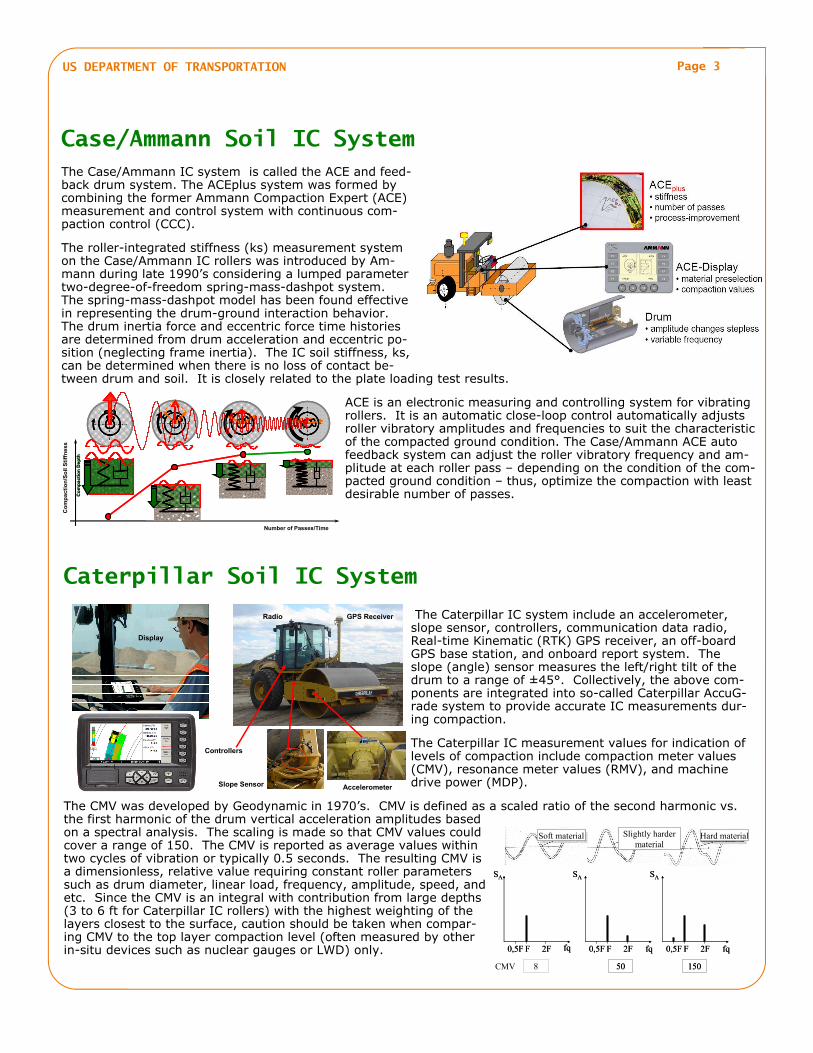
The Case/Ammann IC system is called the ACE and feed-back drum system. The ACEplus system was formed by combining the former Ammann Compaction Expert (ACE) measurement and control system with continuous com-paction control (CCC).
The roller-integrated stiffness (ks) measurement system on the Case/Ammann IC rollers was introduced by Am-mann during late 1990’s considering a lumped parameter two-degree-of-freedom spring-mass-dashpot system. The spring-mass-dashpot model has been found effective in representing the drum-ground interaction behavior. The drum inertia force and eccentric force time histories are determined from drum acceleration and eccentric po-sition (neglecting frame inertia). The IC soil stiffness, ks, can be determined when there is no loss of contact be-tween drum and soil. It is closely related to the plate loading test results.
ACE is an electronic measuring and controlling system for vibrating rollers. It is an automatic close-loop control automatically adjusts roller vibratory amplitudes and frequencies to suit the characteristic of the compacted ground condition. The Case/Ammann ACE auto feedback system can adjust the roller vibratory frequency and am-plitude at each roller pass – depending on the condition of the com-pacted ground condition – thus, optimize the compaction with least desirable number of passes.
Case/Ammann Soil IC System
Caterpillar Soil IC System
The Caterpillar IC system include an accelerometer, slope sensor, controllers, communication data radio, Real-time Kinematic (RTK) GPS receiver, an off-board GPS base station, and onboard report system. The slope (angle) sensor measures the left/right tilt of the drum to a range of ±45°. Collectively, the above com-ponents are integrated into so-called Caterpillar AccuG-rade system to provide accurate IC measurements dur-ing compaction.
The Caterpillar IC measurement values for indication of levels of compaction include compaction meter values (CMV), resonance meter values (RMV), and machine drive power (MDP).
The CMV was developed by Geodynamic in 1970’s. CMV is defined as a scaled ratio of the second harmonic vs. the first harmonic of the drum vertical acceleration amplitudes based on a spectral analysis. The scaling is made so that CMV values could cover a range of 150. The CMV is reported as average values within two cycles of vibration or typically 0.5 seconds. The resulting CMV is a dimensionless, relative value requiring constant roller parameters such as drum diameter, linear load, frequency, amplitude, speed, and etc. Since the CMV is an integral with contribution from large depths (3 to 6 ft for Caterpillar IC rollers) with the highest weighting of the layers closest to the surface, caution should be taken when compar-ing CMV to the top layer compaction level (often measured by other in-situ devices such as nuclear gauges or LWD) only.
Co
mp
ac
tio
n/S
oil
Sti
ffn
es
s
Number of Passes/Time
Co
mp
acti
on
Dep
thC
om
pac
tio
n D
epth
GPS Receiver Radio
Slope Sensor Accelerometer
Controllers
Display
F0,5F 2F fq
SA
F0,5F 2F fq
SA
8
F0,5F 2F
SA
fq
150
F0,5F 2F
SA
fq
150
F0,5F 2F
SA
fq
50
F0,5F 2F
SA
fq
50CMV
Soft material Hard materialSlightly hardermaterial
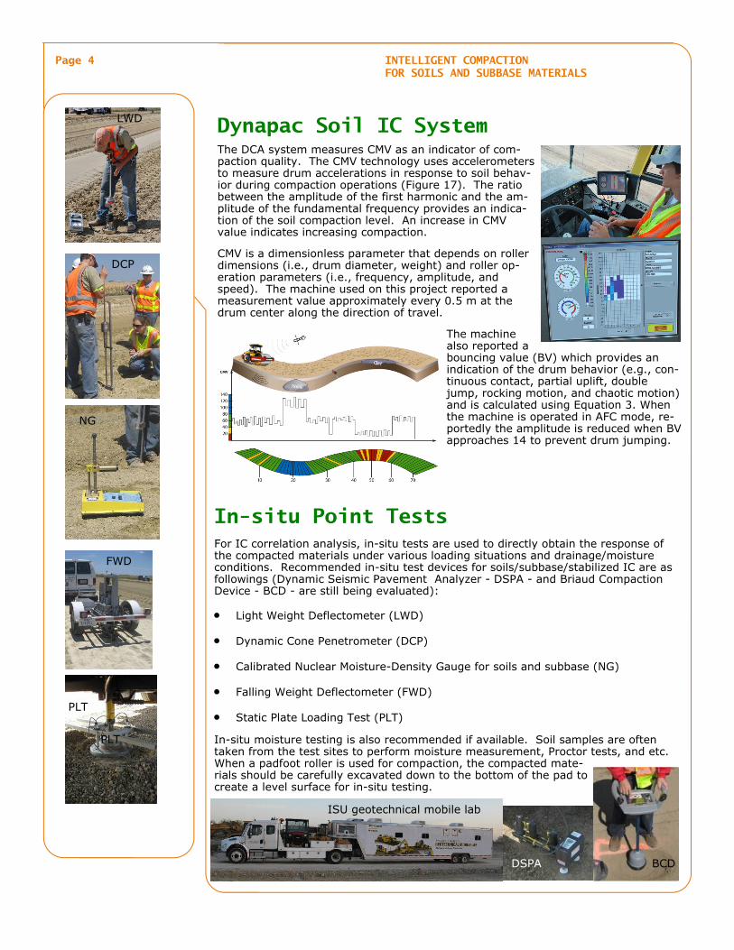
The DCA system measures CMV as an indicator of com-paction quality. The CMV technology uses accelerometers to measure drum accelerations in response to soil behav-ior during compaction operations (Figure 17). The ratio between the amplitude of the first harmonic and the am-plitude of the fundamental frequency provides an indica-tion of the soil compaction level. An increase in CMV value indicates increasing compaction.
CMV is a dimensionless parameter that depends on roller dimensions (i.e., drum diameter, weight) and roller op-eration parameters (i.e., frequency, amplitude, and speed). The machine used on this project reported a measurement value approximately every 0.5 m at the drum center along the direction of travel.
The machine also reported a bouncing value (BV) which provides an indication of the drum behavior (e.g., con-tinuous contact, partial uplift, double jump, rocking motion, and chaotic motion) and is calculated using Equation 3. When the machine is operated in AFC mode, re-portedly the amplitude is reduced when BV approaches 14 to prevent drum jumping.
Dynapac Soil IC System
For IC correlation analysis, in-situ tests are used to directly obtain the response of the compacted materials under various loading situations and drainage/moisture conditions. Recommended in-situ test devices for soils/subbase/stabilized IC are as followings (Dynamic Seismic Pavement Analyzer - DSPA - and Briaud Compaction Device - BCD - are still being evaluated):
Light Weight Deflectometer (LWD)
Dynamic Cone Penetrometer (DCP)
Calibrated Nuclear Moisture-Density Gauge for soils and subbase (NG)
Falling Weight Deflectometer (FWD)
Static Plate Loading Test (PLT)
In-situ moisture testing is also recommended if available. Soil samples are often taken from the test sites to perform moisture measurement, Proctor tests, and etc. When a padfoot roller is used for compaction, the compacted mate-rials should be carefully excavated down to the bottom of the pad to create a level surface for in-situ testing.
In-situ Point Tests
Page 4 INTELLIGENT COMPACTION FOR SOILS AND SUBBASE MATERIALS
LWD
DCP
NG
FWD
PLT
ISU geotechnical mobile lab
DSPA BCD
PLT

US DEPARTMENT OF TRANSPORTATION Page 5
The Global Positioning System (GPS) is a location system based on satellite signals and their ground stations. Depending on the quality of the receiver, the environ-ment, the type of measurements made, and how the measurements are processed, the positioning accuracy of GPS can vary from a few meters to below 1 centimeter, permitting a wide range of positioning applications from vehicle navigation to stud-ies of the motion of the Earth's tectonic plates.
GPS is used in the IC system to record the coordinates of rollers at each pass. However, there are several external sources that may introduce errors into a GPS position including: atmospheric conditions, ephemeris errors/clock drift/measurement noise, selective availability, multipath, and etc.
The IC systems normally use differential correction GPS (or DGPS) to improve ac-curacies. Differential correction requires a second GPS receiver, a base station, collecting data at a stationary position on a precisely known point (e.g., a surveyed benchmark). With the known physical location of the base station, a correction factor can be computed by comparing the known location with the GPS location determined by using the satellites. Then, the correction factor can be applied to the GPS data collected by a GPS receiver in the field.
Recommended GPS requirements for IC are as follows:
RTK-GPS (Real Time Kinematic-GPS) system (radio and receiver) on IC rollers.
System reports and records values in Northing and Easting and vertical position in meters in UTM coordinates for the project site.
If an offset is necessary between GPS antenna and center of drum, the IC sys-tem settings and GPS measurements have to be validated onsite.
Current RTK-GPS system for IC may require a GPS base station, though stand-alone systems are evolving to obtain desirable accuracy.
The Universal Transverse Mercator Coordinate (UTM) system provides coordinates, northings and eastings, on a world wide flat grid for easy computation. Therefore, UTM is normally used in the IC data processing. The Universal Transverse Mercator Coordinate system divides the Earth into 60 zones, each being 6 degrees longitude wide, and extending from 80 degrees south latitude to 84 degrees north latitude. The polar regions are excluded. The first zone starts at the International Date Line (longitude 180 degrees) proceeding eastward. Cautions should be taken when the area of interest extends from one zone to another.
Under this IC study, the UTM zones are restricted in the US from zone No. 10 to zone No. 19. It is recommended that all in-situ test locations are measured using portable DGPS systems and reported with the same UTM zone as IC data.
Global Positioning System (GPS)
Displays measurements and Guides the Operator
Accelerometer on drum Measures soil stiffness as an indication of Soil Compaction
GPS Base Station =
Centimeter accuracy
GPS Records & MapsThe Compaction Results
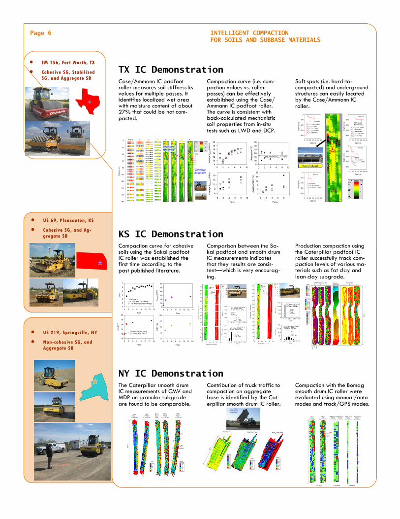
Case/Ammann IC padfoot roller measures soil stiffness ks values for multiple passes. It identifies localized wet area with moisture content of about 27% that could be not com-pacted.
Compaction curve (i.e. com-paction values vs. roller passes) can be effectively established using the Case/Ammann IC padfoot roller. The curve is consistent with back-calculated mechanistic soil properties from in-situ tests such as LWD and DCP.
Soft spots (i.e. hard-to-compacted) and underground structures can easily located by the Case/Ammann IC roller.
Contribution of truck traffic to compaction on aggregate base is identified by the Cat-erpillar smooth drum IC roller.
The Caterpillar smooth drum IC measurements of CMV and MDP on granular subgrade are found to be comparable.
Compaction with the Bomag smooth drum IC roller were evaluated using manual/auto modes and track/GPS modes.
TX IC Demonstration
NY IC Demonstration
Comparison between the Sa-kai padfoot and smooth drum IC measurements indicates that they results are consis-tent—which is very encourag-ing.
Production compaction using the Caterpillar padfoot IC roller successfully track com-paction levels of various ma-terials such as fat clay and lean clay subgrade.
KS IC Demonstration Compaction curve for cohesive soils using the Sakai padfoot IC roller was established the first time according to the past published literature.
Page 6 INTELLIGENT COMPACTION FOR SOILS AND SUBBASE MATERIALS
US 69, Pleasanton, KS
Cohesive SG, and Ag-gregate SB
FM 156, Fort Worth, TX
Cohesive SG, Stabilized SG, and Aggregate SB
Dis
tan
ce (
m)
0
20
40
60
80
100
120
140
160
180
Pass 1 2 3 4 5 6 7 8
Lane12345
Localized Wet Area
Cohesive Subgrade
Pass
0 2 4 6 8 10
Ave
rage
EL
WD
-Z2 (M
Pa)
6
9
12
15
18
0 2 4 6 8 10
Ave
rage
w (
%)
5
10
15
20
25
30
35
Pass
0 2 4 6 8 10
Ave
rage
CB
R (
%)
3
6
9
12
15
18
0 2 4 6 8 10
Ave
rag
e k S
IPD (
MN
/m)
8
10
12
14
16
18
20
Std. Proctor wopt = 17.8%
CBR (%)
0 10 20 30 40 50 60
Dep
th (
mm
)
0
200
400
600
800
Point 13
CBR (%)
0 10 20 30 40 50 60
Dep
th (
mm
)
0
200
400
600
800
Point 12
DCP refusal(Box Culvert)
CBR (%)
0 10 20 30 40 50 60
Dep
th (
mm
)
0
200
400
600
800
Point 5
CBR (%)
0 10 20 30 40 50 60
Dep
th (
mm
)
0
200
400
600
800
Point 1
Point 1
Point 5
Point 12
Point 13
w = 29.5% d = 13.8 kN/m3
ELWD‐Z2 = 11.6 MPa
ELWD‐Z2 = 58.4 MPaEV1 = 96.9 MPaEV2 = 381.1 MPaEFWD‐D3 = 145 MPaED‐SPA = 88 MPa
w = 20.8% d = 16.0 kN/m3
ELWD‐Z2 = 61.1 MPa
ELWD‐Z2 = 47.5 MPaEV1 = 42.1 MPaEV2 = 121.1 MPaEFWD‐D3 = 57 MPaED‐SPA = 44 MPa
Box Culvert
Pass
0 2 4 6 8 10 12 14
CC
V
1
2
3
4
5
6
7
Pass
0 2 4 6 8 10 12 14
EL
WD
-Z2
(MP
a)
0
10
20
30
40
50
60
Pass
0 2 4 6 8 10 12 14
d (
kN/m
3 )
10
12
14
16
18
20
Pass
0 2 4 6 8 10 12 14
CB
R (
%)
0
5
10
15
20
Values corrected using w% values after Pass 1
TB 4 Lane 3: a = 2.19 mm, v = 6 km/h, f = 26 Hz (High amp setting)
MDP for Pass Number1 2 3
Elevation (Pass #3)
Elev. (m)
>245.67245.67245.06244.45243.84243.23242.62<242.62
Passes>987654321
28
0 m
Pass Number1 2 3MDP80
>1401351301251201150
US 219, Springville, NY
Non-cohesive SG, and Aggregate SB
CMVPass 2
a = 0.90 mm
CMVPass 3
a = 0.90 mm
200
m
MDP40
Pass 1Static
MDP40
Pass 2a = 0.90 mm
MDP40
Pass 3a = 0.90 mm
MDP40
>145140135130125120
CMV>100806040200
In-SituTest
Locations
(1)
(2)
(3)
(4) (5)
(6)
(7)
(8)
(9)
(10)
MDP40
>140130120110100900
76 m
CMV>100806040200
Passes>987654321
MDP40 Final PassPass Count CMV Final Pass
Truck traffic contributing to
compaction
Truck traffic contributing to
compaction
Map 1Manual
a = 0.70 mm
Map 2Auto
amax = 1.90 mm
Map 5 Lane 3Manual
a = 0.70 mm
Map 6 Lane 3Manual
a = 1.10 mm
Lane 1
23
4
5
Map 3 Lane 3Manual
a = 0.70 mm
Map 4 Lane 3Manual
a = 0.70 mm
Track ModeGPS Mode GPS Mode
US DEPARTMENT OF TRANSPORTATION Page 7
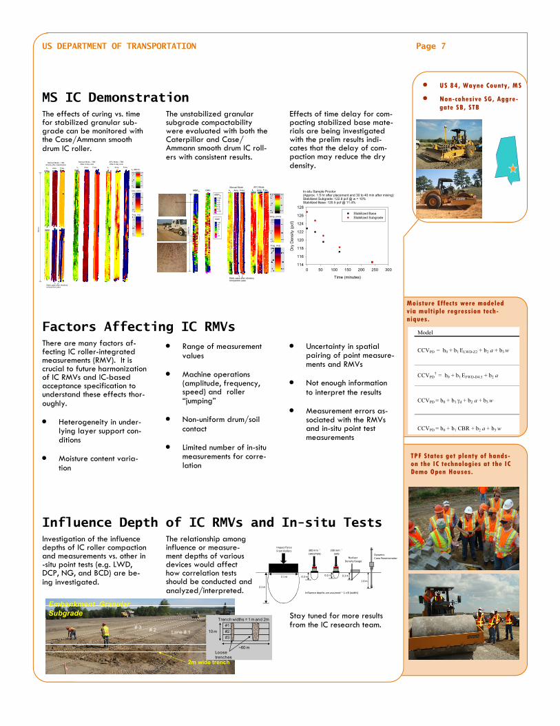
The effects of curing vs. time for stabilized granular sub-grade can be monitored with the Case/Ammann smooth drum IC roller.
The unstabilized granular subgrade compactability were evaluated with both the Caterpillar and Case/Ammann smooth drum IC roll-ers with consistent results.
Effects of time delay for com-pacting stabilized base mate-rials are being investigated with the prelim results indi-cates that the delay of com-paction may reduce the dry density.
The relationship among influence or measure-ment depths of various devices would affect how correlation tests should be conducted and analyzed/interpreted.
Investigation of the influence depths of IC roller compaction and measurements vs. other in-situ point tests (e.g. LWD, DCP, NG, and BCD) are be-ing investigated.
Stay tuned for more results from the IC research team.
MS IC Demonstration
Influence Depth of IC RMVs and In-situ Tests
Range of measurement values
Machine operations (amplitude, frequency, speed) and roller “jumping”
Non-uniform drum/soil contact
Limited number of in-situ measurements for corre-lation
Uncertainty in spatial pairing of point measure-ments and RMVs
Not enough information to interpret the results
Measurement errors as-sociated with the RMVs and in-situ point test measurements
Factors Affecting IC RMVs There are many factors af-fecting IC roller-integrated measurements (RMV). It is crucial to future harmonization of IC RMVs and IC-based acceptance specification to understand these effects thor-oughly.
Heterogeneity in under-lying layer support con-ditions
Moisture content varia-tion
US 84, Wayne County, MS
Non-cohesive SG, Aggre-gate SB, STB
ks
Amp. (mm)
Freq. (Hz)
Amp. Freq.
Manual Mode - TB4Shortly after stabilization
ks Amp. Freq.
AFC Mode - TB9After 2-day cure
ks (MN/m)
304
m
ks Amp. Freq.
Manual Mode - TB9After 2-day cure
Static pass after vibratory compaction pass
109
.5 m
MDP40
>140140130120110100<100
CMV
>2020151052<2
MDP40 CMV ks
Amp. (mm)
Freq. (Hz)
Amp. Freq. ks Amp. Freq.Manual Mode AFC Mode
Static pass after vibratory compaction pass
Time (minutes)
0 50 100 150 200 250 300
Dry
De
nsity
(pc
f)
114
116
118
120
122
124
126
128
Stabilized BaseStabilized Subgrade
In-situ Sample Proctor (Approx. 1.5 hr after placement and 30 to 40 min after mixing):Stabilized Subgrade: 122.8 pcf @ w = 10%Stabilized Base: 120.5 pcf @ 11.4%
2m wide trench
1m wide trench
Lane # 1# 2# 3
Embankment Granular Subgrade
10 m
~60 m
Trench widths = 1 m and 2m
Loose trenches
#1
#2
#3
Impact ForceFrom Rollers 300 mm
LWD/FWD200 mm
LWD
Nuclear Density Gauge
DynamicCone Penetrometer
2.1 m
2.1 m
0.3 m 0.2 m 0.3 m
1.0 m
Influence depths are assumed ~ 1 x B (width)
Moisture Effects were modeled via multiple regression tech-niques.
Model
CCVPD = b0 + b1 ELWD-Z2 + b2 a + b3 w
CCVPD†
= b0 + b1 EFWD-D4.5 + b2 a
CCVPD = b0 + b1 d + b2 a + b3 w
CCVPD = b0 + b1 CBR + b2 a + b3 w
TPF States get plenty of hands-on the IC technologies at the IC Demo Open Houses.

Contact — Victor (Lee) Gallivan, P.E. — [email protected] FHWA Office of Pavement Technology, 575 N. Pennsylvania St., Indianapolis, Indiana 46204, (317) 226-7493
George Chang, Ph.D., P.E. — [email protected] The Transtec Group, 6111 Balcones Drive, Austin TX 78731. (512) 451-6233 extension 227
Research — This TechBrief was developed by Dr. George Chang and Qinwu Xu from the Transtec Group. The project team also includes: Dr. Robert Otto Rasmussen and David Merritt of the Transtec Group, Larry Michael of LLM Asphalt Consulting, Dr. David White of Iowa State University, and Bob Horan of the Asphalt Institute.
Distribution — This TechBrief is being distributed according to a standard distribution. Direct distribution is being made to FHWA’s field offices.
Availability — This technical brief is freely available from the FHWA DTFH61-07-C-R0032 research project team “Accelerated Im-plementation of Intelligent Compaction technology for Embankment Soils, Aggregate Base, and Asphalt Pavement Materials”. The goal of this technical brief is to better inform the public about this study.
Key Words — compaction, intelligent compaction, roller, soils, subgrade, aggregate, embankment, stabilized base, asphalt, HMA, pavement performance, quality control, quality assurance.
Notice — This TechBrief is disseminated under the sponsorship of the U.S. Department of Transportation in the interest of infor-mation exchange. The TechBrief does not establish policies or regulations, nor does it imply Federal Highway Administration (FHWA) endorsement of any products or the conclusions or recommendations presented here. The U.S. Government assumes no liability for the contents or their use.
Quality Assurance Statement — FHWA provides high-quality information to serve Government, industry, and the public in a man-ner that promotes public understanding. Standards and policies are used to ensure and maximize the quality, objectivity, utility, and integrity of its information. FHWA periodically reviews quality issues and adjusts its programs and processes to ensure con-tinuous quality improvement.
Benefits of Intelligent Compaction
Improve Density…
better performance Improve Efficiency…
cost savings Increase Information…
better QC/QA
Validation of the IC Global Positioning Sys-
tem (GPS) setup prior to the compaction
operation using a survey grade GPS hand-
held unit is crucial to providing precise and
correct measurements.
To correlate in-situ tests with IC data prop-
erly, in-situ test locations must be estab-
lished using a hand-held GPS “rover” unit
that is tied into the project base station and
offers survey grade accuracy.
Use of IC RMVs can be as part of intelligent
QC/QA. Further study on linking IC RMVs to
mechanistic QA parameters in top 1~3 m
are strongly recommended.
Standardization is strongly recommended to
accelerate the implementation IC for State
agencies: a standard IC data storage for-
mat, an independent viewing/analysis soft-
ware tool, and detailed data collection plan
Recommendations