implementation of pem hydrogen generation into an existing ... · pdf fileadditionally, the...
TRANSCRIPT

Page 1 of 16
IMPLEMENTATION OF PEM HYDROGEN GENERATION INTO AN EXISTING UPPER AIR NETWORK Peter Lejbjuk P.Eng ‐ Observing Systems and Engineering
Environment EnvironnementCanada Canada
Meteorological Service of Canada 4905 Dufferin St, Toronto Ontario, Canada ‐ M3H 5T4
Tel.: 1(416)739‐4526, eMail: [email protected]
ABSTRACT
Environment Canada currently uses helium gas to launch balloons at 17 of 31 upper air
network sites. The remaining stations use hydrogen gas, generated by an aging alkaline
electrolysis system. The rising acquisition and delivery costs of helium gas combined with
concerns regarding the reliability of existing hydrogen generation have initiated a project to
update Upper Air Network sites with modern hydrogen generators using Proton Exchange
Membrane (PEM) technology. The contrasting requirements between the alkaline system and a
PEM system present several challenges. Additionally, hydrogen safety standards developed since
the original implementation of the alkaline system over 30 years prior require thorough review.
This paper illustrates the challenges faced in the process of designing and implementing a
modern hydrogen gas generation system that effectively combines safety and reliability into a
cost effective solution.
1.0 INTRODUCTION
Environment Canada has recently committed to
updating the existing Upper Air Network with modern
hydrogen generation equipment ‐ replacing aging
alkaline hydrogen generation equipment and costly
helium storage and delivery programs.
The replacement generator, provided by Proton
Energy Systems (Model HOGEN S40), uses a proton
exchange membrane (PEM) cell to produce hydrogen
from purified water and electricity. Unlike the
network`s existing alkaline units, this modern
generator operates autonomously without chemicals
and offers advanced features for safety and
monitoring system integration. These additional
features combined with dissimilar operating
requirements make the installation of these
generators into the network more complex than
simply physically replacing the current generators.
The following paper will explain these complexities
beginning by briefly reviewing the hazards associated
with hydrogen and the operation/requirements of the
HOGEN S40 generator. It will also describe the
challenges encountered when developing a
specification to implement the HOGEN and discuss the
operation of the safety systems used to protect the

Page 2 of 16
Figure 3.1: The HOGEN S40 Hydrogen Generator
operator and facility from the inherent dangers
associated with gaseous hydrogen.
2.0 HYDROGEN HAZARDS
Despite being 75% of the universe’s elemental
mass, hydrogen gas is not a commonly found in
everyday life in a concentrated form. It is well known
for its flammability and low density, the latter making
it ideal for filling buoyant vessels such as weather
balloons (H2 is 8% more buoyant than He).
The hazards associated with hydrogen extend
beyond its high flammability. Hydrogen burns
extremely fast, with a laminar burning velocity 9 times
that of gasoline; it is combustible over a very wide
range of mixtures in air (4% to 75% by volume); and
can be ignited with very little energy ‐ less than you
would feel in a static shock. The gas is colourless and
odourless making it difficult to detect, and it burns
with a nearly invisible flame.
Hydrogen also presents challenges due to its small
molecular size. Hydrogen embrittlement is a
mechanism where metals exposed to hydrogen can
lose ductility due to permeation of hydrogen
molecules into their crystal lattice structure; leading to
premature failure. Hydrogen’s small molecular size
also makes it difficult to contain since it is able to
escape through passages that larger molecules would
not. These are important characteristics to note when
selecting components and materials to be used in
hydrogen systems.
3.0 THE HOGEN GENERATOR
The HOGEN S40 is a `site ready` enclosed unit that
is roughly the size of a household clothes washing
appliance (figure 3.1). The unit produces 99.9995%
purity H2 at 13.8bar (200psi) without mechanical
compression at a rate of 1.05SCM/hr. To accomplish
this, the unit must consume ASTM Type2+ (10MΩ
resistivity) quality water at a rate of 1.0L/hr. The water
quality represents the first challenge faced when
updating to a PEM generator from an alkaline unit. In
contrast, the outgoing alkaline generator required
water purity of Type4 (0.2MΩ). This increased quality
requires a reagent grade water purification system to
supply the HOGEN generator. Operating a PEM cell
with insufficient water quality will drastically reduce
the lifespan of the cell due to damage incurred at the
membrane from impurities.
Additionally, the outgoing alkaline generator
produced lower purity H2 at ambient pressure,
requiring mechanical compression to increase
pressure to the storage and dispensing level of 6.9bar
(100psi). The low storage pressure, combined with
high moisture content in the H2 gas, required a large
pressure vessel to be located in a non‐freezing indoor
space, beside the alkaline generator. In contrast, the
higher pressure and purity (‐65°C dew point) produced
by the HOGEN generator allows for a much smaller
pressure vessel to be located in a freezing

Page 3 of 16
Figure 3.2: The PEM Electrolysis Process
environment away from the generator and associated
control systems.
The basic operating principle of the HOGEN
generator is essentially a hydrogen fuel cell process in
reverse. The PEM cell unit, located centrally in the
generator, introduces purified reagent grade water to
a catalytic surface which splits H2O into H+ protons and
O2. The H+ is driven through the membrane by
electrical current where it combines with electrons on
the other side producing H2 at pressure. It is important
to note that both sides of the PEM cell are ‘wet’, one
side containing water saturated with oxygen, the
other water saturated with hydrogen (Figure 3.2).
These saturated solutions are separated within the
generator and the hydrogen product is sent through a
dryer process bringing the purity to 99.9995%. This
dryer process creates a ‘wet’ hydrogen by‐product at a
rate of 10% of the hydrogen gas generation. The by‐
product must be safely vented outside the building.
Care must be taken if venting to a freezing
temperature since the high moisture content can
create a frozen ice plug that blocks by‐product
ventilation.
Oxygen is another by‐product of the hydrogen
production, produced at 50% the rate of product
hydrogen. Due to the difference in pressures within
the electrolysis cell, a breach in the proton exchange
membrane pushes hydrogen saturated water into the
oxygen side of the cell. For this reason, the generator
uses a combustible gas sensor to detect hydrogen in
the oxygen by‐product and will halt production if a
hazardous condition exists. Oxygen is typically vented
immediately outside the generator since it does not
present a hazard nor does it reduce the lower
flammability threshold of hydrogen.
It is also worth noting the heat by‐product of the
generation process. As with a hydrogen fuel cell, the
electrolysis process is not 100% efficient. The HOGEN
generator produces up to 4200W of heat while
generating which requires consideration when
planning room temperature controls for the area in
which the generator is placed.
One of the greatest advantages of a modern
hydrogen generator is the ability to integrate with
more comprehensive safety systems. The HOGEN unit
offers relay controlled outputs for remote alarms
indicating detected faults in the generator as well as
relay controlling inputs capable of halting production
and powering down the generator remotely via an
emergency stop switch, or an output from a
monitoring system. Since the HOGEN generator is
controlled by a processor, remote telemetry is

Page 4 of 16
possible through an internet connection allowing
service and maintenance activities to be planned more
effectively ‐ especially for remote sites.
4.0 SPECIFICATION DEVELOPMENT
Development of a comprehensive specification
document to retrofit the new HOGEN generators into
existing Upper Air Network sites began with a
thorough analysis of the current applicable codes and
standards related to hydrogen systems and explosive
atmospheres.
The codes and standards researched involved two
main categories; codes regarding area classification,
containment, and approved equipment for explosive
atmospheres; and standards regarding the generation,
transmitting, storage, and dispensing of gaseous
hydrogen. The latter often covers aspects of the
former and was therefore the logical place to start.
4.1 HYDROGEN CODES AND STANDARDS
Much of the useful information found regarding
the criteria that should be given consideration when
designing a hydrogen system came from “Basic
considerations for the safety of hydrogen systems –
ISO 15916”. This document provides an excellent
consolidation of the information that is scattered
throughout many of the other standards available. It is
also written with the objective of simplifying the
arduous process of regulatory compliance and is
specific to hydrogen. Another helpful document
examined was the NASA standard “Safety Standard for
Hydrogen and Hydrogen Systems – NSS 1740.16”
which discussed in more detail the many safety
considerations, the types of components/materials
recommended, and information on procedures/best
practices when working with hydrogen ‐ both in the
gaseous liquid forms.
It is important to note that when reviewing
standards and codes, their scope should be
considered. As the hydrogen alternative energy
industry grows, codes and standards shift towards
controlling hazards inherit with commercial quantities.
For example the “Canadian Hydrogen Installation Code
– CAN/BNQ 1784‐000” was created to remove the
barriers slowing the development of hydrogen
technologies and allow for the development of a
hydrogen economy. The code is focused on the
commercial storage and dispensing of hydrogen, and
as such, references quantities at magnitudes greater
than what would be used in a meteorological balloon
site. Many of the National Fire Protection Agency
(NFPA) codes make early reference to threshold
quantities of stored hydrogen below which the
regulations do not apply.
These threshold quantities, often referred to as the
Maximum Allowed Quantity (MAQ) were used to
determine the hydrogen storage vessel volume in the
specification (750L). This represents enough hydrogen
to launch 5 balloons, doubling the network standard
of 2.5 balloons reserve lift gas. This is not to say that
reviewing the standards that apply to commercial
quantities of hydrogen did not provide valuable
information and design elements which were relevant
to the meteorological application. However, as the
duty of navigating the complexities of regulations can
be quite tedious, distinguishing features that must be
applied from those that can be applied did save
considerable time in specification development.
The second category of applicable regulations
examined dealt with the subject of area classification
and explosion rated equipment. Several codes exist,
the most prevalent ones being the international code
IEC‐60079, the European code EN‐60079, and the
National Electrical Code (chapter 5). The Canadian
Electrical Code (chapter 18) was used as the authority

Page 5 of 16
Figure 4.1: Zone and Division Levels
for sites in the Environment Canada network. Each
code was found to vary slightly; however there
appeared to be consensus on how to classify
atmospheres and what design aspects and equipment
are allowed in a classified atmosphere.
4.2 AREA CLASSIFICATION
Establishing area classification was the first step to
applying the regulations and selecting powered
equipment.
The first layer of the area classification process
involved the material state of the combustible fuel. An
area that contains a combustible gas or liquid
becomes a Class I atmosphere. Three atmosphere
classes exist; Class 2 –dusts, and Class 3 –fibres and
fillings.
The next layer involved the more subjective
process of establishing the probability that an
explosive atmosphere may exist. In the zone system,
three zones exist:
Zone 0 is an atmosphere where an explosive
mixture is continuously present, or present for long
periods of time.
Zone 1 is an atmosphere where an explosive
mixture is likely to occur in normal operation.
Zone 2 is an atmosphere where an explosive
mixture is not likely to occur and if it occurs will
exist for a short period of time.
In contrast, the two level division system combines
Zone 0 and Zone 1 into a single area referred to as
Division 1. Division 2 is equivalent to Zone 2.
The final layer of the area classification process
involved specifying the exact combustible material
involved by selecting the appropriate group. These
groups are created based on the combustion
properties such as pressure, temperature, and ignition
energy. Hydrogen is classified as a Group B gas by the
North American codes, and as a IIC Group by the
European and I.E.C. codes. It is second in hazard level
only to Acetylene in the North American codes. In the
European and I.E.C. codes Hydrogen and Acetylene
occupy the same group.
To summarise, the only decision process required
in a meteorological application using hydrogen was to
establish the applicable zone or division. Hydrogen is
by default Class 1, and Group B (IIC). In determining
the zone several resources were consulted. The NFPA
497 code dealt specifically with examples of common
occurrences where classification is not straight
forward. Further research indentified accepted
techniques used to ‘de‐classify’ a zone using a purge
and pressurize system as described in NFPA 496.
It was noted that the zone assessment process
required the evaluation of the probability of an
explosive atmosphere existing, and by definition an
explosive atmosphere first requires a combustible
mixture to be achieved. For example, a very small
hydrogen leak will introduce hydrogen to an oxygen
rich environment, but will take time to achieve a 4%

Page 6 of 16
Figure 4.2: The aftermath of a hydrogen incident in Baker Lake,
Nunavut ‐1979. No injuries occurred however the building was
destroyed.
by volume mixture with air (the lower flammable limit
of hydrogen). If sufficient ventilation is present, it may
be impossible to reach an explosive atmosphere.
Additionally; if hydrogen detection is employed, a
system response such as additional ventilation or the
emergency stoppage of the generator can prevent an
explosive atmosphere from ever existing.
The HOGEN generator is a good example of this
methodology. The unit itself generates and contains
pressurized hydrogen, and although under normal
conditions it does not leak hydrogen, it does fall into
the Zone 2 classification since under abnormal
circumstances it is capable of leaking hydrogen.
However, the HOGEN unit is not a classified area and
is not certified to be installed in an explosive
atmosphere. This is achieved by a purge and
pressurizes process, whereby the unit pumps air
through the cabinet at a rate one thousand times
greater than the maximum production rate of
hydrogen. The ventilation is interlocked to hydrogen
production by a cabinet pressure switch, where if
ventilation were to fail hydrogen production would
halt. By this method, an explosive atmosphere is not
possible and therefore the cabinet is ‘de‐classified’.
4.3 OPERATIONAL REQUIREMENTS
In developing the implementation specification, a
careful examination of the operational requirements
of the network sites was completed. This began with
several site visits to understand the current
operational procedures and how they might be
impacted by the introduction of the new generator. It
was observed that several areas offered opportunities
for improvement to safety. These opportunities were
made possible by the additional functionality of the
new generator’s integration capability. Additional
issues were identified that can be attributed to the era
from which these original systems were installed over
thirty years ago. Many of the design aspects identified
in the codes and standards reviewed were applied to
provide additional fail‐safes in abnormal operating
conditions.
4.4 PAST PROBLEM HISTORY
As with any complex project, moving forward
without first taking the opportunity to learn from the
past can be a critical error. The existing Upper Air
Network has been in operation for decades and
provides a wealth of knowledge and experience when
examined carefully. Records of incidents were
reviewed as well as interviews conducted with
experienced site operators. Several issues were
identified and reflected to the specification
development.
Additional historical data was researched from
outside the meteorological community. The ISO 15916
document included a summary of the common causal
factors in hydrogen accidents. Similar information and
studies have been performed and are available on the
internet with careful searching. One website that was
found to have a wealth of incident investigations was
www.h2incidents.org.
In examining both internal and external problem
history a clear trend was observed. In the majority of
Page 7 of 16
hydrogen accidents, human error was attributed as
the predominant causal factor. This was followed by
errors or omissions in operating procedures. It was
noted that in developing the specification for a
meteorological application, autonomous fail‐safe
systems and clear operating procedures must be a
priority.
4.5 RESOURCE STATUS
One project objective in the implementation of the
new generators was to reuse whatever existing
equipment was feasible. A careful assessment of
existing resources and their status was conducted. It
was found that for the most part sites required no
major overhauling activity to accept the new system.
In most cases, the sites followed a standard
configuration established in the past when the
previous alkaline generators were installed. In the case
of the alkaline system, the generator was not designed
with the same high level of fail‐safe as the HOGEN
unit, and was therefore classified as a Zone 2 area.
This required the generation room to be outfitted with
explosion rated lights, heaters, switches, and for all
wiring to be installed in sealed conduit tubing. These
systems are still viable to be used with the new
generator and system layout, since they offer a level
of protection well above the minimum required for a
non‐explosive atmosphere.
Another resource that required careful
examination was the site water quality. Because the
new generator would require extensive water
processing, a baseline needed to be established to
ensure any processing equipment specified could
handle the quality of incoming water and provide
reasonable service intervals.
At many sites in the Canadian network, water must
be delivered and stored on site since wells are not
feasible in permafrost conditions. At other sites, well
water is of questionable quality. For those reasons a
survey was conducted to establish water quality and
the filtration system was sized on those results.
Electrical power quality was also a concern due to
the sensitive nature of the power supplies used in the
HOGEN generator. Since many Upper Air Network
sites are located in remote northern areas, power is
often supplied by a diesel generator. A power line
conditioning system was developed to ensure large
voltage transients and low voltage situations would
not damage the generator.
5.0 SYSTEM DESIGN
The design of the support systems that would be
required to retrofit the new generator into existing
sites began with a process map (Figure 5.1) and
comprehensive schedule.
The design focus was shared between system
safety and system reliability, identified as project
‘viewpoints’ from the research performed in the body
of knowledge processes discussed above.
A concept configuration was drafted to provide a
starting point for iterative analysis with respect to the
project viewpoints.
Viewpoints were then subjected to a rigorous Fault
Tree Analysis (FTA) process where each potential
failure mode of the concept design was broken down
to singular causal factors. These factors were then
paired with designed systems and fail‐safes to ensure
that system safety and reliability were maintained. It
was necessary to carefully balance the safety and
reliability viewpoints, since an extensive and complex
safety system may compromise reliability, and vice
versa, a robust and reliable system may not have the
necessary fail‐safes in place to ensure safety.

Page 8 of 16
Each designed system characteristic and failsafe
was then made into a Key Quality Point (KQP) where it
was grouped by system (ex: ventilation system, safety
system, hydrogen plumbing system... etc). From there
the KQP’s were matured by examining their
compatibility, availability, cost, and ultimately
feasibility of incorporating them in the system design
specification. The following sections briefly describe
the key characteristics of each system prefaced by an
explanation of the area classification assessment
results that provided the foundation of the
specification.
5.1 AREA CLASSIFICATION RESULT
The existing inflation building structures located on
Upper Air Network sites include two rooms in the
standard configuration layout. One room is used to fill
the balloon. It includes a fill table and two large roll up
doors. It is unheated and uses passive ventilation by
means of vents in the lower wall and a peaked roof
with vents at the apex. The other room, adjacent to
the inflation room, houses the generator and storage
tank along with a dispensing valve to fill the balloon.
With the alkaline generator system installed, the
inflation room was classified as Zone 1 and the
generation room was Zone 2. There was a doorway
between the two rooms used to enter the inflation
room from the generation room once the balloon was
filled and ready for attachment of the radiosonde.
In consideration of the requirements of the new
generator, the area classification was revised to
maintain the Zone 1 classification for the inflation
room, but making the generation room a non‐
explosive atmosphere (unclassified). This was
necessary simply because the HOGEN generator was
not approved for installation in an explosive
atmosphere. The reclassification required the
elimination of the doorway between the two rooms.
By the area classification code, an area adjacent to a
Zone 1 area that is connected by a doorway or passage
is by default a Zone 2 area.
The storage tank was also moved from the
generation room to the inflation room where it posed
Figure 5.1: System Design Process Map

Page 9 of 16
a lower risk and allowed the generation room to
remain unclassified. This was not possible with the
alkaline generation system because the tank required
a positive temperature environment.
5.2 HEATING AND VENTILATION
The HOGEN generator requires a minimum room
ventilation rate of one hundred times the production
rate of hydrogen. Because the HOGEN generator itself
uses a purge technique to eliminate the risk of an
explosive atmosphere accumulating, the same
technique must be applied to the room where it is
installed. Failure to do so would only transfer
hydrogen from inside the HOGEN cabinet to the room
where it could concentrate to the lower flammability
limit of 4% by volume.
One challenge identified early in the project was
the impact that a high rate of air exchange with the
outdoor environment would have on energy
consumption, especially in northern climates. The heat
output of the generator during generation process
somewhat offsets this loss, however ventilation was
required during times when generation was not
occurring due to the presence of a small amount of
hydrogen in the generator and lines exiting the
machine.
A Heat Recovery Vent (HRV) unit was specified to
provide the necessary efficiency in heating the
generation room, however the large potential
temperature differential between outdoor and indoor
air required special consideration to be given to the
frost build up that would occur in the heat exchanger.
Most HRV’s operate on a timed cycle of ventilation
and recirculation to address this frosting issue and can
therefore not provide continuous ventilation with
outside air. A tandem interlocked pairing of HRV’s
provided the necessary solution allowing one HRV to
defrost while the other maintained the necessary air
exchange rate. A flow switch was also specified to
interlock the air circulation with hydrogen production,
much like the logic employed in the HOGEN generator.
5.3 WATER PURIFICATION
Proton Energy Systems recommended a water
purification unit to accompany the HOGEN generator
(Figure 5.2). The water purifier, supplied by
AquaSolutions, uses a Reverse Osmosis (RO) and
Deionization (DI) process to filter tap water to the
necessary level of purity for the PEM cell to operate
without risk of damage. Due to the remote location of
many of the network’s sites, water storage was also
necessary. Storage volume specified was based on the
water quality survey results and ranged from 1000‐
2500L, using an agricultural style plastic tank. The tank
was placed in the generation room near the HOGEN
generator. By placing the tank close to the generator,
it also functioned as a thermal mass in the event room
heating were to fail. The thermal inertia of a large
volume of water provided a small but valuable margin
of freezing protection for the costly PEM cell.
Figure 5.2: The AuqaSolutions Water Purifier
Page 10 of 16
The HOGEN generator consumes purified water at
a rate of 1.0L/hr; however the water purifier rejects
up to four times the water it sends to the generator
(depending on the initial water quality), making the
total maximum water consumption of the system
5L/hr. The water purifier also requires water to be
supplied at pressure, so a pump and accumulator were
included in the specification to ensure the necessary
input pressure. A pre‐filter was also used ahead of the
water purifier to guarantee the minimum tap water
quality (<1000TDS) was maintained.
The HOGEN generator itself includes an additional
internal DI cartridge to ‘polish’ the incoming water
from the water purification unit. The generator also
monitors water resistivity and is able to reject water of
insufficient quality.
One major source of poor water quality to note is
contamination after the purification process. Type 2+
level reagent water is extremely pure, and is therefore
very aggressive. It is starved of ions and will draw
them from materials it comes in contact with ‐ even
absorbing CO2 if exposed to air. Materials such as
copper, PVC, stainless steel, and cast iron were
specifically excluded in the specification as they can
destroy the water quality and rapidly damage the PEM
cell. Further precautions were necessary in the
handling of components that would be in contact with
the purified water during maintenance per Proton’s
recommendations.
5.4 HYDROGEN STORAGE AND PLUMBING
In researching acceptable materials for hydrogen
service, 316 series stainless‐steel (316SS) was the most
frequently recommended. This was due to the
material’s resistance to hydrogen embrittlement,
which was far superior to materials such as alloy steels
like 4140 or 1042. The resistance is due to the face‐
centred‐cubic (FCC) crystal structure of austenitic
stainless‐steels, which unlike alloy steels with a body‐
centred‐cubic (BCC) crystal structure; do not allow
disassociated hydrogen atoms to permeate as easily.
Additional consideration was necessary for the
operating temperature the storage and plumbing
components would be subjected to. Since the new
generator provided ultra pure hydrogen virtually free
from moisture, the tank was specified to be located in
the unheated inflation room. A minimum performance
temperature requirement of ‐50°C was specified. In
many cases, special order valve seals using ethylene
propylene seat material were required to perform at
low temperatures.
The hydrogen storage tank was constructed from
316SS and designed for a maximum pressure of
20.7bar (300psi), 50% higher than the maximum
output of the generator. Redundant pressure relief
devices were specified as per recommendations in
many of the standards reviewed. The secondary relief
device incorporated a manual override which doubled
as a manual purge valve.
One voluntary design aspect extracted from
commercial applications was an emergency discharge
device (EDD). This was not a regulatory requirement
based on the quantity of hydrogen stored; however it
did provide an additional layer of safety in the event of
a fire where the tank contents could be remotely
evacuated to the outdoors. This was accomplished by
adding a solenoid valve in parallel with the primary
and secondary safety relief valves.
To mitigate the risk of leakage, the dispensing
circuit layout was changed from the standard
configuration used with the alkaline generators.
Previously, hydrogen was dispensed to the balloon
table via a quarter turn ball valve located in the
generation room, beside the doorway linking the

Page 11 of 16
inflation and generation rooms. This provided an
opportunity for two main failure modes. First, the
valve could fail and leak, allowing hydrogen to escape
to the generation room. Second, the valve itself
provided no ‘dead‐man’ function. By replacing the
valve with a remotely operated solenoid valve located
in the inflation room with the tank, the risk to the
generation room was eliminated. Additionally, the
solenoid valve was remotely actuated from the
generation room and a momentary switch was
specified requiring the operator to continuously press
the switch to maintain hydrogen flow. Another
valuable function the remotely actuated valve allowed
was the ability to use the safety system to disable
dispensing automatically. Two solenoid valves were
specified for redundancy with a flow switch used to
detect valve failure to close. It is important to note
that only normally closed valves were specified, a two
position valve would not close in the event of power
loss to the system.
Additional manual valves were specified at tank
inputs and output to facilitate safe repair to the
generation and dispensing circuits. These valves
functioned to isolate these circuits in the event of a
detected failure, or for necessary repair. No isolation
valves were used on the primary safety relief circuits
and EDD as this would bring the risk of the isolation
valve accidentally being shut disabling the safety
relief.
Check valves were used extensively as safety
devices to control flow direction. The most critical
check valve was installed in the storage tank inlet
where hydrogen entered via the generator in the
generation room. By installing a check valve, any leak
that may occur in the generation room circuits would
only spill the contents of those circuits, which was
minimal, and what the generator was producing ‐ at a
very slow rate. Conversely, without the check valve, a
leak in the generator room could drain the entire 750L
tank into the room, rapidly achieving the lower
flammability limit. Other check valves functioned to
prevent the complete drainage of the storage tank.
Check valves block flow in one direction, while
allowing it in the other. A cracking pressure was
specified for the allowed flow direction that essentially
functioned as a low pressure switch whereby if the
tank were to be drained below the cracking pressure
of the check valve, flow would be stopped. It was
important to ensure that the atmosphere inside the
storage tank remained pure hydrogen. By draining the
tank to empty, oxygen may be allowed to enter,
creating a potentially combustible mixture at the
upper flammability limit of 75% and requiring the tank
to be purged.
The storage tank included both an analogue
pressure gauge and a pressure transducer. The latter
served as a remote pressure monitor so that no
analogue gauge was required in the generation room.
This followed the same logic as the solenoid operated
dispensing valves. No hydrogen circuits would be
allowed in the generation room that weren’t
absolutely necessary.
5.5 SAFETY SYSTEM
The safety system represents the highest work
load of the specification planning since it lays the
foundation for all the mechanical and electrical
systems that must support it.
The primary objective in developing a safety
system was to include both redundancy and autonomy
to ensure the same level of safety regardless of
operator experience level.
Specification design began with a hazard
assessment based on the decided classification of each
room. Items identified in FTA activity were

Page 12 of 16
incorporated into the system logic. Each room was to
be outfitted with both hydrogen and flame detection
units. Despite the generation room being unclassified,
gas and fire detection was specified as an additional
layer of safety and in most cases already existed due
to their necessity with the alkaline generation system
The gas detector specified was an explosion rated
device using a catalyst bead detection method
calibrated for hydrogen gas (Figure 5.3). The unit
provided both digital communication outputs and
analogue relay outputs. Two detection levels were
specified, one at 20% of the lower flammability limit
(1% hydrogen in air overall), a second threshold at
40% of the lower flammability limit. The response for
the first limit involved a warning in the form of an
audible alarm and light and shut down of all non‐
essential powered systems. The second triggered an
immediate shut down of all electrical systems that
were not rated for an explosive atmosphere as well as
additional alarms. Each gas detector was outfitted
with a ‘scoop’ which was recommended by the
manufacturer when trying to detect lighter than air
gases. The scoop captured rapidly rising hydrogen to
improve detector sensitivity and accuracy. Detectors
were installed directly above the highest risk area with
previsions for calibration –required every ninety days.
The fire detection unit offered the same outputs
and operated on a three spectrum (UV‐Visible‐IR)
optical scanning principle. The unit required line‐of‐
sight, making placement critical to realizing the full
benefit. The visual detection method was chosen over
the more common room temperature monitoring for
its faster response and performance, especially in the
inflation room which is unheated.
Both the gas and flame detection sensors included
fault detection, alerting the safety system when they
became disabled.
A central control unit was mounted in a partitioned
area of the generation room to allow the detection
circuits to maintain operation in the event gas or fire
was detected in the generation room.
Additional sensors monitored gas flow in the
dispensing circuit, air flow in the ventilation circuit,
and temperature in the generation room. Due to the
damage that would occur if the generator were
exposed to freezing temperatures, an alarm was also
specified to alert operators of a problem with the
heating system.
The safety system was also tied to the HOGEN
generator to allow the system to disable the generator
in the event of a gas leak or fire, and to allow the
HOGEN generator to alert the safety system of a
internal fault.
Both the HOGEN generator and safety system were
outfitted with provisions to be connected to a network
allowing remote monitoring of all controlled
parameters. This provided technicians with the
opportunity to assess issues before traveling to
remote sites making maintenance and repairs more
timely and efficient.
Provisions were specified in the safety system for a
backup analogue logic system in the event the more Figure 5.3: An Explosion Proof Combustible Gas Detector

Page 13 of 16
complex digital system was to become disabled. Relay
outputs from the detectors were connected to
contactors in the main building breaker panel to
disable priority systems at the programmed set points.
This was not the preferred mode of operation since it
did not incorporate the remote network monitoring
function, however in the interest of maintaining
reliability in a network where a technician may be as
many as three days away, a backup ‘simple’ system
offered additional robustness at little cost.
5.6 ELECTRICAL SYSTEM
Many of the aspects of the electrical system
specification were extracted directly from the
Canadian Electrical Code. As with all codes examined
that include provisions and equipment for explosive
atmospheres, specific methods and materials are
approved for the fabrication of electrical circuits.
Conduit was required for all electrical connections
in the inflation room, and for the detection circuits in
the generation room.
Circuits and equipment that were not rated for an
explosive atmosphere were mounted close to the
floor, to provide additional safety in case of a gas leak.
Although they would be disabled in the event of gas
detection, mounting low to the floor in an
environment where the combustible gas is known to
rise was considered good practice.
Explosion rated lighting and electric heaters were
previously installed with the alkaline generation
system and did not need replacement.
All metal surfaces in the building were bonded and
confirmed using ground validation equipment. A
grounded metal surface was also provided for the
operator to ground themselves upon entering the
building.
5.7 BUILDING PREPARATION
Many of the structures that are to be retrofit
require some level of repair. Along with these repairs,
additional insulation was specified to increase the
thermal efficiency and work in conjunction with the
HRV’s to reduce overall operating costs of the site.
As mentioned, the doorway between the inflation
and generation rooms was removed and replaced with
a window to allow the operator to fill the balloon from
the safety of the generation room. Operators would
be required to exit the generation room to the
outdoors and then re‐enter the inflation room from
outside.
No passages were allowed between the inflation
and generation rooms. All hydrogen and electrical
connections were sealed, along with the wall at the
floor and ceiling. Latex paint was specified for
generous application to the walls and ceiling of the
generation room.
A passive ceiling vent was incorporated into the
generation room at its highest point to allow hydrogen
to escape in the unlikely event a leak occurs and the
mixture reaches a flammable level shutting down the
powered ventilation. The vent was minimally sized to
prevent heat loss.
6.0 SUMMARY
Implementation of a PEM hydrogen generation
system into an existing network of Upper Air sites
requires a thorough understanding of the hazards
involved in hydrogen systems. Many aspects of the
specification developed for Environment Canada’s
project were extracted from the wealth of knowledge
and experience that is available in the many codes and
standards available for hydrogen and explosive
atmospheres. Additional information on problem

Page 14 of 16
history and lessons learned was given by a careful
review of both internal and external hydrogen
accidents and near‐misses.
In developing project viewpoints, used to focus
development towards critical objectives, the risk of
human error and incomplete procedures were
identified as the greatest source of hazard. Multiple
redundancy, safety system autonomy, and fail‐safe
devices are design features that are paramount in
reducing these hazards, as well as teamwork between
those providing training to operators and those who
layout the system specification.
Component selection was made easier by first
understanding the unique requirement of hydrogen
systems and the mechanical failure modes these
systems are susceptible to. More and more
manufacturers are offering components that are
designed for use with hydrogen as the world’s
hydrogen economy grows, making it easier to select
the right materials for the operating conditions.
Ultimately, the task of developing a specification is
heavily influenced by national codes which vary
slightly in detail by region. A meteorological
application is difficult to compare to a commercial or
industrial hydrogen system, but a careful selection of
system size and storage volume can separate a
meteorological application from the regulations that
were developed for large scale hydrogen systems.
Included with this paper is a system schematic
representing the layout of the described hydrogen
plumbing and storage system. Additional information
is available on request.
REFERENCES:
ISO/PDTR 15916 ‐ Basic Considerations for the Safety of Hydrogen Systems, International Organization for Standardization, 2004
NSS 1740.16 ‐ Safety Standard for Hydrogen and Hydrogen Systems, National Aeronautics and Space Administration (NASA), 1996
C22.1‐06 ‐ Canadian Electrical Code, Canadian Standards Association, 2006
C22.1HB‐06 ‐ CE Code Handbook, Canadian Standards Association, 2006
NFPA 496 – Standard for Purged and Pressurized Enclosures for Electrical Equipment, National Fire Protection Association, 2008
NFPA 497 – Recommended Practice for the Classification of Flammable Liquids, Gases, or Vapors and of Hazardous (Classified) Locations for
Electrical Installations in Chemical Process Areas, National Fire Protection Association, 2008
CAN/BNQ 1784‐000/2007 – Canadian Hydrogen Installation Code, National Standard of Canada / Bureau de Normalisation du Quebec, 2007
NFPA 69 – Standard on Explosion Prevention Systems, National Fire Protection Association, 1997
NFPA 50A – Standard for Gaseous Hydrogen Systems at Consumer Sites, National Fire Protection Association, 1999
NFPA 55 – Standard for the Storage, Use, and Handling of Compressed Gases and Cryogenic Fluids in Portable and Stationary Containers, Cylinders,
and Tanks, National Fire Protection Association, 2005
H2 Incident Reporting and Lessons Learned, Pacific Northwest National laboratory/US Department of Energy, www.h2incidents.org
H2 Safety Best Practices, Pacific Northwest National Laboratory / Los Alamos National Laboratory / US Department of Energy,
www.h2bestpracticess.org
Yoshihide Suwa et al, Design of Safe Hydrogen Refuelling Stations Against Gas‐Leakage Explosion and Accidental Automobile Collision, Obayashi
Corporation, Tokyo 2006

Page 15 of 16
Metering ValveSet flow rate to
meet 15g/s requirement and
lock out.
Quick Connect CouplingAllows for easy switching of fill hose supply.
Balloon Fill NozzleStandard nozzle used at
all upper air sites.
Check Valve (5psi)Prevents tank contamination from back flow if tank is run to empty.
Solenoid Actuated Normally Closed ValvePrimary safety valve to immediately turn off H2supply to inflation room if leak, fire, or ESD is detected.
Check Valve (5psi)Prevents tank contents from draining into generator room if a leak occurs.
Two 2-Way Drain ValvesRedundant valve to prevent valve leak from requiring tank to be emptied and re-purged.
Relief Valve @ 250psiRelieves tank pressure above set point. Primary safety device. 4-Way Junction
Use larger diameter tubing for
unrestricted flow
Non-Heated Vent StackTank contents contain no water vapour. Therefore freezing is not a concern. Measures to be taken to prevent water/contaminant/animal ingress
Check Valve (5psi)Prevents tank contamination if drain valve is accidentally left open.
Inflation Room
2-Way Isolation ValveIsolates dispensing line for servicing solenoid valves.
2-Way Isolation ValveIsolates tank filling line for servicing HOGEN
H2 Storage TankApproved for hydrogen service, rated for 300psi.
Solenoid Actuated Normally Closed ValveRemote dispensing valve allows entire dispensing system to be outside generation room.
Analogue Gauge (0-300psi)Displays tank pressure at tank location provided isolation valve is open.
Pressure Transducer (0-300psi)Sensor to detect tank pressure for remote display in generator room and operations building. Using remote sensing eliminates the risk of an analogue gauge leaking in the generation room.
Relief Valve @ 250psiRelieves tank pressure
above set point. Primary safety device.
2-Way Isolation ValveIsolates pressure
measurement for servicing and confirming gauges
Solenoid Actuated Normally Closed ValveEmergency Discharge Valve (EDD) used in case of fire. (voluntary code compliance)
2-Way Purge ValveUsed as vent for water purge
Tee JunctionNPT at one end for Swage-to-NPT fitting (allows positioning)
Tee JunctionNPT at one end for Swage-to-NPT fitting (allows positioning)
Flow SwitchSwitch to detect failure of the solenoid valves. If valves leak, or fail to close, switch will detect flow and sound alarm. Operator must then close manual isolation valve and solenoid valves must be repaired.
From Generator Room
Metering ValveSet flow rate to
meet 15g/s requirement and
lock out.
Quick Connect CouplingAllows for easy switching of fill hose supply.
Balloon Fill NozzleStandard nozzle used at
all upper air sites.
Balloon Fill NozzleStandard nozzle used at
all upper air sites.
Check Valve (5psi)Prevents tank contamination from back flow if tank is run to empty.
Solenoid Actuated Normally Closed ValvePrimary safety valve to immediately turn off H2supply to inflation room if leak, fire, or ESD is detected.
Check Valve (5psi)Prevents tank contents from draining into generator room if a leak occurs.
Two 2-Way Drain ValvesRedundant valve to prevent valve leak from requiring tank to be emptied and re-purged.
Relief Valve @ 250psiRelieves tank pressure above set point. Primary safety device. 4-Way Junction
Use larger diameter tubing for
unrestricted flow
Non-Heated Vent StackTank contents contain no water vapour. Therefore freezing is not a concern. Measures to be taken to prevent water/contaminant/animal ingress
Check Valve (5psi)Prevents tank contamination if drain valve is accidentally left open.
Inflation Room
2-Way Isolation ValveIsolates dispensing line for servicing solenoid valves.
2-Way Isolation ValveIsolates tank filling line for servicing HOGEN
H2 Storage TankApproved for hydrogen service, rated for 300psi.
Solenoid Actuated Normally Closed ValveRemote dispensing valve allows entire dispensing system to be outside generation room.
Analogue Gauge (0-300psi)Displays tank pressure at tank location provided isolation valve is open.
Pressure Transducer (0-300psi)Sensor to detect tank pressure for remote display in generator room and operations building. Using remote sensing eliminates the risk of an analogue gauge leaking in the generation room.
Relief Valve @ 250psiRelieves tank pressure
above set point. Primary safety device.
2-Way Isolation ValveIsolates pressure
measurement for servicing and confirming gauges
Solenoid Actuated Normally Closed ValveEmergency Discharge Valve (EDD) used in case of fire. (voluntary code compliance)
2-Way Purge ValveUsed as vent for water purge
Tee JunctionNPT at one end for Swage-to-NPT fitting (allows positioning)
Tee JunctionNPT at one end for Swage-to-NPT fitting (allows positioning)
Flow SwitchSwitch to detect failure of the solenoid valves. If valves leak, or fail to close, switch will detect flow and sound alarm. Operator must then close manual isolation valve and solenoid valves must be repaired.
From Generator Room
Figure 6.1: Illustrated Schematic of the Storage and Dispensing Circuits
Page 16 of 16
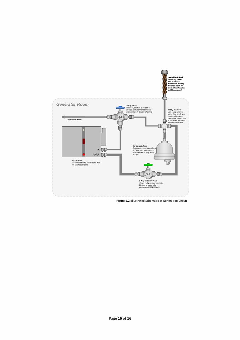
Heated Vent StackElectrically heated vent to outdoor atmosphere. Heating prevents wet H2 by-product from freezing and blocking vent.
3-Way ValveAllows H2 product to be sent to storage tank (normal operation), or to vent stack (trouble shooting)
2-Way Isolation ValveAllows H2 by product port to be blocked to assist with diagnosing HOGEN faults.
4-Way JunctionUse 4-way junction rather than two 3-way junctions to reduce connection points. Vent to stack and trap must be oriented vertical.
Condensate TrapSeparates condensation from H2 by product and drains to building drain or gray water storage.
HOGEN S40Shown are the H2 Product and Wet H2 By-Product ports.
H2
H2 +H2O
Generator Room
To Inflation Room
Heated Vent StackElectrically heated vent to outdoor atmosphere. Heating prevents wet H2 by-product from freezing and blocking vent.
3-Way ValveAllows H2 product to be sent to storage tank (normal operation), or to vent stack (trouble shooting)
2-Way Isolation ValveAllows H2 by product port to be blocked to assist with diagnosing HOGEN faults.
4-Way JunctionUse 4-way junction rather than two 3-way junctions to reduce connection points. Vent to stack and trap must be oriented vertical.
Condensate TrapSeparates condensation from H2 by product and drains to building drain or gray water storage.
HOGEN S40Shown are the H2 Product and Wet H2 By-Product ports.
H2
H2 +H2O
H2
H2 +H2O
Generator Room
To Inflation Room
Figure 6.2: Illustrated Schematic of Generation Circuit