implementation of building information modeling for · pdf fileimplementation of building...
TRANSCRIPT

Implementation of Building Information Modeling for Wafer Fab Construction
by
Shruthi Pindukuri
A Thesis Presented in Partial Fulfillment
of the Requirements for the Degree
Master of Science
Approved April 2011 by the
Graduate Supervisory Committee:
Allan Chasey, Chair
Avi Wiezel
Michael Mamlouk
ARIZONA STATE UNIVERSITY
May 2011

i
ABSTRACT
Semiconductor manufacturing facilities are very complex and capital
intensive in nature. During the lifecycle of these facilities various disciplines
come together, generate and use a tremendous amount of building and process
information to support various decisions that enable them to successfully design,
build and sustain these advanced facilities. However, a majority of the
information generated and processes taking place are neither integrated nor
interoperable and result in a high degree of redundancy.
The objective of this thesis is to build an interoperable Building
Information Model (BIM) for the Base-Build and Tool Installation in a
semiconductor manufacturing facility. It examines existing processes and data
exchange standards available to facilitate the implementation of BIM and
provides a framework for the development of processes and standards that can
help in building an intelligent information model for a semiconductor
manufacturing facility.
To understand the nature of the flow of information between the various
stakeholders the flow of information between the facility designer, process tool
manufacturer and tool layout designer is examined. An information model for the
base build and process tool is built and the industry standards SEMI E6 and SEMI
E51 are used as a basis to model the information.
It is found that applications used to create information models support
interoperable industry standard formats such as the Industry Foundation Classes
(IFC) and ISO 15926 in a limited manner. A gap analysis has revealed that

ii
interoperability standards applicable to the semiconductor manufacturing industry
such as the IFC and ISO15926 need to be expanded to support information
transfers unique to the industry. Information modeling for a semiconductor
manufacturing facility is unique in that it is a process model (Process Tool
Information Model) within a building model (Building Information Model), each
of them supported more robustly by different interoperability standards.
Applications support interoperability data standards specific to the domain or
industry they serve but information transfers need to occur between the various
domains. To facilitate flow of information between the different domains it is
recommended that a mapping of the industry standards be undertaken and
translators between them be developed for business use.

iii
This is for my loving husband.

iv
ACKNOWLEDGMENTS
I would like to express my deepest gratitude to Dr. Allan Chasey for his patience,
guidance and continuous support throughout my graduate studies. I would like to
thank Dr. Avi Wiezel and Dr. Michael Mamlouk for their support of my thesis. I
would like to thank Mike Alianza and Dan Hodges of Intel for helping me gain
industry exposure. I would like to thank the CREATE office for supporting my
graduate studies. Lastly, I would like to thank my parents and husband for their
patience and support.
v
TABLE OF CONTENTS
Page
LIST OF TABLES ...................................................................................................... ix
LIST OF FIGURES ..................................................................................................... x
CHAPTER
1. Introduction................................................................................................ 1
1.1 Background ................................................................................... 1
1.2 Problem Statement ........................................................................ 4
1.3 Hypothesis..................................................................................... 5
1.4 Objective ....................................................................................... 5
1.5 Scope ............................................................................................. 6
2. Literature Study ......................................................................................... 7
2.1 Semiconductor Manufacturing Facilities ..................................... 7
2.1.1 Cleanroom Standards ................................................. 7
2.1.2 Wafer Size .................................................................. 8
2.1.3 Line Width ................................................................. 9
2.1.4 Wafers per Month (WPM) ......................................... 9
2.1.5 Characteristics of Semiconductor Manufacturing
Facilities .............................................................................. 9

vi
Chapter Page
2.2 Semiconductor Manufacturing Facility – Base Build + Tool
Install ................................................................................................. 10
2.2.1 Base Build ................................................................ 11
2.2.2 Process Tool Installation .......................................... 14
2.3 Building Information Modeling (BIM) ...................................... 20
2.3.1 Background .............................................................. 20
2.3.2 Challenges of Traditional Approaches ..................... 21
2.3.3 Building Information Modeling- Definition ............ 23
2.3.4 Pre-Construction and Post-Construction Benefits to
Owner ................................................................................ 24
2.3.5 Design Benefits to Architects and Engineers ........... 26
2.3.6 Construction Benefits to Contractors ....................... 28
2.3.7 Building Information Modeling Benefits for
Subcontractors and Fabricators ......................................... 31
2.3.8 Parametric Modeling ................................................ 32
2.4 Interoperability ............................................................................ 33
2.4.1 Industry Foundation Classes (IFC) .......................... 36
2.4.2 Information Delivery Manual (IDM) ....................... 43
2.4.3 International Framework for Dictionaries (IFD) ..... 45

vii
Chapter Page
2.4.4 ISO 15926 - "Industrial automation systems and
integration‖ ....................................................................... 49
2.4.5 Other Data Standards – STEP, IGES ....................... 59
2.4.6 SEMI Standards for Semiconductor Manufacturing
Facilities ............................................................................ 60
2.4.7 SEMI E51: Guide for Typical Facilities Services and
Termination ....................................................................... 64
2.5 Building Information Modeling for Semiconductor
Manufacturing Facilities ................................................................... 65
3. METHODOLOGY .................................................................................. 72
3.1 Hypothesis................................................................................... 72
3.2 Methodology ............................................................................... 72
3.2.1 Tool Information Model .......................................... 73
3.2.2 Building Information Model .................................... 78
3.2.3 Tool Layout Design – Tool Information Model +
Building Information Model ............................................. 82
4. RESULTS ................................................................................................ 85
4.1 Scenario – 1 Export of the Tool Information Model to Facility
Owner/Designer ................................................................................ 85
4.3 Scenario 3 and 4 - Import Tool Information Model and Building
Information Model for Tool Layout Design .................................... 89

viii
Chapter Page
4.4 Scenario 5 and 6 - Export Tool Information Model and Building
Information Model to Autodesk Inventor and Revit MEP .............. 90
4.5 Limited Adoption of Industry Standards IFC /ISO 15926 ........ 91
4.6 Alignment in the Adoption of Industry standards IFC /ISO
15926 ................................................................................................. 92
5. FUTURE DIRECTION ......................................................................... 101
5.1 IFC for Semiconductor Manufacturing Facilities .................... 102
5.2 ISO 15926 for Semiconductor Manufacturing Facilities ........ 104
5.3 Translator for IFC and ISO 15926 ........................................... 106
REFERENCES ...................................................................................................... 108
APPENDIX
A SEMI DRAFT DOCUMENT 3287 - REVISION TO E6, GUIDE
FOR SEMICONDUCTOR EQUIPMENT INSTALLATION
DOCUMENTATION ................................................................. 112
B SEMI E51-0200 GUIDE FOR TYPICAL FACILITIES SERVICES
AND TERMINATION MATRIX .............................................. 118
C SEMI PERMISSION TO PUBLISH PORTIONS OF SEMI E6 0303
AND SEMI E51 0200 ................................................................. 122
D TOOL LAYOUT DESIGN ............................................................. 124

ix
LIST OF TABLES
Table Page
1. SEMI E6 Data Sheet Table (SEMI 2003).. ....................................................... 61
2. SEMI E51 – Series 100 - Equipment Identification Data Sheet (SEMI 2003)..61
3. Categories of facility data (SEMI 2000).. ......................................................... 64
4. Site Specific Facilities Service and Termination Matrix .................................. 65
5. Summary of the most common exchange formats in the AEC area ................. 87
6. Mapping IFC and ISO15926 ............................................................................. 94
7. Gap Analysis of SEMI E51 Water Services Data Sheet against the IFC ......... 98
8. Gap Analysis of SEMI E6 Water Services Data Sheet against the ISO 15926
……………………………………………………………………………………99

x
LIST OF FIGURES
Figure Page
1. Classification of Air Cleanliness ........................................................................ 8
2. Components of Semiconductor Manufacturing Facility ................................... 11
3. Tool Installation Design Information Flow ...................................................... 18
4. Tool Startup Sequence and Operational Transfer. ............................................ 20
5. Time versus Ability to Impact Cost .................................................................. 21
6. Indexes of Labor Productivity .......................................................................... 22
7. Contingency/Reliability as a Function of Project Phases. ................................ 25
8. Value Added, Cost of Changes and Current Compensation Distribution for
Design Services. .................................................................................................... 27
9. Snapshot of a Contractor and Subcontractor using BIM to Support MEP
Coordination ......................................................................................................... 29
10. 4D view of Construction of Vancouver Convention Center showing
Foundation and Structural Steel Erection ............................................................. 30
11. Improved Visualization – Moving from paper based methods to digital 3D
models ................................................................................................................... 32
12. Interoperability through Standards ................................................................. 35
13. IFC, IFD and IDM components of the data exchange triangle ....................... 37
14. IFC Architecture – IFC 2x3 ............................................................................ 41
15. IDM – Architecture ......................................................................................... 45
16. IFD Library ..................................................................................................... 48
17. buildingSMART Propertylizer Tool ............................................................... 49

xi
Figure Page
18. ISO15926 Components of the Data Exchange Triangle ................................. 50
19. History of ISO 15926 ...................................................................................... 52
20. Parts of ISO 15926 .......................................................................................... 53
21. Example of Template ...................................................................................... 55
22. Reference Data Federation .............................................................................. 59
23. E6XML Schema.............................................................................................. 63
24. Facility Construction Process ......................................................................... 68
25. Semiconductor Tool Design and Installation Process .................................... 71
26. Flow of Information between Tool Manufacturer, Facility Owner/Designer
and Tool Layout Designer .................................................................................... 73
27. Tool Information Model ................................................................................. 77
28. Tool Information Model from supplier imported into Revit MEP ................. 79
29. Building Information Model ........................................................................... 80
30. BIM from Semiconductor Manufacturer Exported to IFC and imported to
Revit Architecture ................................................................................................. 81
31. Tool Layout Design ........................................................................................ 83
32. Scenario 1 Information transfer between Tool Manufacturer and Facility
Owner/Designer .................................................................................................... 85
33. Scenario 2 Information transfer from Facility Owner/Designer to Tool
Manufacturer ......................................................................................................... 88
34. Scenario 3 and 4 Information transfer from Tool Manufacturer and Facility
Owner/Designer to Tool Layout Designer ............................................................ 89

xii
Figure Page
35. Scenario 5 and 6 Information transfer from Tool Layout Designer to Tool
Manufacturer and Facility Owner/Designer ......................................................... 90
36. Description of Temperature in IFC ................................................................. 94
37. Description of Temperature in ISO 15926...................................................... 95
39. IFC for Semiconductor Manufacturing Facilities ......................................... 104
40. ISO 15926 for Semiconductor Manufacturing Facilities .............................. 106

1
1. Introduction
1.1 Background
Semiconductor Manufacturing facilities are very complex and capital intensive in
nature. Construction of these facilities often involves high levels of uncertainty,
strict spending limits, aggressive schedules and fast track construction. During the
various stages of the lifecycle of these facilities different disciplines come
together, generate and use a tremendous amount of building and process
information to support various decisions that enable them to successfully design,
build and sustain these advanced facilities. In the highly fragmented construction
industry, a majority of the information and processes taking place throughout the
life cycle are neither integrated nor interoperable and result in a high degree of
redundancy. The National Institute of Standards and Technology‘s (NIST) study
‗Cost Analysis of Inadequate Interoperability in the US Capital Facilities
Industry‘ identifies and quantifies the efficiency loses in the U.S capital facilities
industry attributable to inadequate interoperability to be US $ 15.8 billion in 2002
(NIBS 2007). FIATECH estimates the potential benefits of integration and
automation technology to include; up to 8% reduction in costs for facility creation
and renovation, up to 14% reduction in project schedules and repair cost savings
ranging from 5-15% (FIATECH 2010).
Increasing awareness of the advantages of integrated project delivery methods has
led to the development of various processes and tools by all participants in the

2
facility‘s lifecycle; owners, architects, designers, vendors, builders and operators.
One such significant development is Building Information Modeling. According
to the U.S. National Institute of Building Sciences (NIBS), ―Building Information
Modeling (BIM) is a digital representation of physical and functional
characteristics of a facility. A BIM is a shared knowledge resource for
information about a facility forming a reliable basis for decisions during its life-
cycle; defined as existing from earliest conception to demolition. A basic premise
of BIM is collaboration by different stakeholders at different phases of the
lifecycle of a facility to insert, extract, update or modify information in the BIM
to support and reflect the roles of that stakeholder.‖ (NIBS 2007)
The extended use of 3D intelligent design (models) has led to references to terms
such as 4D (adding time to the model) and 5D (adding quantities and cost of
materials). Perhaps a simpler way is to think of the 3D model as a ―tool‖ then the
applications of its use throughout the planning, design, construction and facility
operation processes are unlimited. Based on this, when coordinating construction
sequencing by integrating schedule data with the model data and calling it ―4D‖,
or doing the same when using the model data to quantify materials and apply cost
information and calling it ―5D,‖ seems arbitrary since these are just two of the
many applications of how the 3D ―tool‖ can be used to improve all of the
processes. Therefore, rather than continuing on with this numbering (6D, 7D, etc.)
there is a growing trend to refer to all of the extended applications using the 3D
tool as ―XD.‖ (Park 2003)

3
Based on the experience of early adopters, the use of interoperable building
information models include; informed design decision-making, rapid iteration of
simulations of building performance and construction sequencing, streamlining
information flow and reducing time-to-complete in certain supply chains, e.g.,
steel, substantially reducing field problems and material waste during
construction, making feasible the off-site fabrication in controlled environments
of larger percentages of the building components and assemblies, increasing their
quality and longevity, and reducing on-site construction activities and materials
staging, creating a less crowded and safer site (Fallon 2007). Many studies and
research projects have proposed other uses of the models such as automated cost
estimations and work space planning. In addition, key owners have recognized the
potential for capturing the information needed to fine-tune building system
performance, establish appropriate maintenance practices and schedules and
evaluate the feasibility of proposed expansions or renovations. Thus, the adoption
of this approach holds benefits for all stakeholders in the full facility lifecycle and
improves outcomes in three major dimensions of performance: cost, schedule and
quality (Fallon 2007).
The semiconductor manufacturing industry in its constant quest to minimize the
cost of its capital intensive facilities and speedy project delivery to match
production to available market window has recognized that the implementation of
BIM can help it achieve these goals. Leading semiconductor manufacturers have
implemented pilot projects using BIM to understand the efficiency gains and the

4
return on investment. BIM has been implemented in both the Base Build as well
as Tool Install portion of the facilities. Limited applications of BIM such as 3D
modeling for visualization and clash detection, 4D construction sequencing and
5D quantity take offs have been implemented. The pilot projects showed
improved operational efficiencies by reducing the number of RFI‘s and Change
orders due to reduced field clashes, reduction in RFI latency time and improved
quality of work in place due to increased prefabrication. Return of Investment was
achieved in large part by the reduction in rework due to field clashes.
1.2 Problem Statement
Current applications of BIM by the semiconductor manufacturing industry are
localized implementations such as considering the flow of information specific to
the scope of the current implementation (such as clash detection, and estimation),
use of proprietary software and data standards. While these localized and specific
processes helped understand the implementation of BIM and its Return on
Investment in a time when the various stakeholders such as software vendors and
standards bodies were developing the necessary infrastructure, they (localized and
specific processes) make it difficult to take the implementation of BIM to the next
level of expanding the applications of BIM and including all the stakeholders in
the project lifecycle. While industry participants are developing business
processes to integrate BIM into the current workflow, technologies and
information standards need to be developed to facilitate this process. It is

5
important to understand the flow of information between all the stakeholders to
for a holistic implementation of BIM and the standards available that can facilitate
the exchange of data.
1.3 Hypothesis
Is it possible to build an intelligent information model for a semiconductor
manufacturing facility that carries the different kinds of information that the
various stakeholders in its lifecycle use? Is it possible to transfer this information
seamlessly between the various stakeholders through all phases its lifecycle from
its development to tool layout design, installation and operation?
1.4 Objective
The objective of this thesis is to build an intelligent information model for a
semiconductor manufacturing facility that serves the needs of the various
stakeholders involved in its lifecycle. It examines the existing processes and data
exchange standards available to facilitate the implementation of BIM and
provides a framework for the development of processes and standards that can
help in building an intelligent information model for a Semiconductor
manufacturing facility.

6
1.5 Scope
The design and construction of a Semiconductor Manufacturing Facility involves
many different stakeholders; Tool Manufacturers, Architects, Industrial
Designers, Structural Designers, Project Management Consultants, Safety
Consultants, Code Compliance Agencies, General Contractors, Mechanical,
Electrical, Plumbing, Fire Protection Subcontractors and facility operators.
Semiconductor manufacturing facilities involve a large variety and number of
toolsets. Understanding and developing business process models and
implementing data exchange standards for all the stakeholders and toolsets of a
semiconductor manufacturing facility would be a huge task. Due to the vast
nature of the area under study, the scope of this thesis will be limited to
Building a generic tool and facility model showing information that is
transferred between the tool supplier, tool layout designer (owner/IE) and
facility designer (A/E)
Explore and identify standards that can help specify and facilitate the data
exchange process between the base build and tool install phases.
1. ISO 15926 – Process industry standards and implementation
methods
2. IFC – Industry Foundation Classes
3. SEMI Standards – SEMI E-6
4. SEMI Standards – SEMI E-51

7
2. Literature Study
A study of past and current developments and literature pertaining to
semiconductor manufacturing facilities, the various aspects of building
information modeling and its challenges, the role of interoperability and data
standards and building information modeling for wafer fab construction are
presented in this section.
2.1 Semiconductor Manufacturing Facilities
Semiconductor manufacturing facilities are large complex facilities that house
people, process systems and tools that manufacture integrated circuits used in
computing (computers, networks, internet), communications (cellphones) and
manufacturing applications (digital appliances). Semiconductor manufacturing
facilities are described in terms of the following:
2.1.1 Cleanroom Standards
The Cleanroom is an integral part of a semiconductor manufacturing facility. It is
an environment with a controlled level of contamination, specified in terms of the
number of particles per cubic meter at a specified particle size. The ISO 14644-1
standards specify the number of particles 0.1 micron or larger permitted per cubic
meter of air. For example, an ISO class 3 cleanroom should have a maximum of
1000 particle >= 0.1 micron per cubic meter of air.

8
Figure 1. Classification of Air Cleanliness (ISO 1999)
2.1.2 Wafer Size
Semiconductor manufacturing facilities are also defined by the size of silicon
wafer they are tooled to produce. Silicon wafers range in size from 25.4 mm to
300 mm. Current state of the art semiconductor manufacturing facilities produce
300mm size wafers with the next generation considered to be 450mm. By far
larger wafer sizes have resulted in increased yield per wafer due to reduced
marginal space remaining over total space available. Though the increase in
wafer size has reduced the cost per unit of silicon it has also substantially
increased the cost of the facility.

9
2.1.3 Line Width
Line width sometimes refers to the narrowest line that could be resolved by the
printing equipment and photoresist (usually the gate electrode and referred to by
designers as the gate length). It also refers to the spacing or linewidth between
each transistor of a wafer and is used by the industry to describe a process; like a
65 nm, 45 nm or 32 nm process.
2.1.4 Wafers per Month (WPM)
WPM refers to the number of wafers produced by a facility in a month.
Traditional 300mm fabs have 20,000 to 30,000 wafer starts per month.
Manufacturers such as Samsung and Hynix have ramped up their production to
80,000 to 110000 wpm. Flash alliance is building the largest fab till date with
over 200,000 wpm capacity.
2.1.5 Characteristics of Semiconductor Manufacturing Facilities
Semiconductor manufacturing facilities are large facilities that are capital
intensive in nature. A traditional 300 mm fab with 20,000–30,000 wpm (in 300
mm) costs about $3-$4B. Economies of scale are forcing a further increase in
volume of output per facility thereby increasing the facility size and costs. Now
the semiconductor industry is entering into an era of mass production of over
200,000 wpm (in 300 mm) capacity fabs costing $9-$10B.

10
The capital intensive nature of the industry requires the facilities to be designed
and constructed faster to quickly yield marketable and reliable products. The time
to market window is a crucial factor in the design and manufacturing of
semiconductor products. The return on investment on the capital intensive
semiconductor manufacturing facilities can be maximized only if they are built in
the right time to meet the market window.
2.2 Semiconductor Manufacturing Facility – Base Build + Tool Install
Design and Construction of a Semiconductor Manufacturing facility consists of
Base build and Tool Install. Base Build portion refers to the building structure,
envelope, the cleanroom (Fab) and sub-fab that houses major mechanical,
electrical and plumbing systems such as HVAC (Heating, Ventilation and Air
Conditioning), electrical, UPW (Ultra-Pure Water) and exhaust systems. The Tool
Install portion refers to the various semiconductor manufacturing equipment
(process tools) installed in the facility such as Thin Film, Dry Etch, Wet Etch,
Diffusion, Lithography and Implant. Another important part of a semiconductor
manufacturing facility are the Process Specific Support Systems (PSSS) such as
gas and chemicals delivery systems (storage, manifold boxes and piping) that are
required for the manufacturing of semiconductors. Figure 2 below shows how the
various systems come together and form the Semiconductor Manufacturing
Facility.

11
Figure 2. Components of Semiconductor Manufacturing Facility
2.2.1 Base Build
The various components of the base build portion of the Semiconductor
manufacturing facility are explained below.
2.2.1.1 Architecture
The design and construction of semiconductor manufacturing facilities involves
consideration of manufacturing requirements which leads to various solution
factors such as cleanroom class, manufacturing requirements, air distribution and
fan systems, wafer handling (automation) etc. The Cleanroom is an integral part
of a semiconductor manufacturing facility. As explained above it is an
Semiconductor Manufacturing Facility
Base Build PSSS Tool Install
Architectural
Structural
HVAC
Electrical
Ultra-Pure Water
Gas & Chemical System
Thin Film
Dry Etch
Wet Etch
Diffusion
Lithography
Implant

12
environment with a controlled level of contamination, specified in terms of the
number of particles per cubic meter at a specified particle size. There are two
types of cleanroom layouts; Ballroom and Bay and Chase layouts. The Ballroom
layout is an open layout with clean minienvironments which house the
semiconductor tools. This type of layout has no walls and allows for flexible tool
layout. However, since there is no air segregation it involves a higher operating
cost. The Bay Chase layout is the traditional layout with clean bays for processing
and less clean chases for equipment and/or return air. The advantages of this
layout include segregation of maintenance, lower airflow and ceiling costs. The
disadvantage is that it is less flexible (Evans 2006).
2.2.1.2 HVAC System
The HVAC system of a semiconductor manufacturing facility is comprised of the
Air Systems (Dry side) and the Water/Steam System (Wet side). The air side
system consists of cleanroom recirculation air, make-up air, process exhaust and
heat exhaust. The cleanroom recirculation air and make up air system ensure
maintaining a clean, particulate free and comfortable working environment for the
people and process systems. The major components of a process exhaust system
include corrosive exhaust, VOC exhaust, pyrophoric exhaust, ammonia and heat.
The wet side system consists of chilled water generation and distribution system,
glycol chilled water generation and distribution system, steam generation and
distribution system and heating water system. Some of the auxiliary HVAC
13
Systems include Process Cooling Water (for the production tools) and Hot
Deionized or Ultrapure Water (for process improvement) (Acorn 2006).
2.2.1.3 Ultra-Pure Water System (UPW)
The UPW system is a critical component of the manufacturing process. Its
purpose is to provide pure water for the removal of other chemicals from the
wafer surface. UPW contacts the wafer at least 20 times during the manufacture
of the devices on the wafer. The UPW process removes particles, dissolved solids
(ions), bacteria, organic matter and dissolved gases from the water before use in
the manufacturing process. The various steps in the purification process include
filtration, chemical treatment, reverse osmosis, degassification, deionization,
ultraviolet sterilization and ozonation. The UPW system is usually located in the
Central Utilities Building (CUB). The system is sized based on the proposed
production equipment list with the tools and diversity factor (Loper 2006).
2.2.1.4 Gas and Chemical Systems
Gases and chemicals are the building blocks for manufacturing integrated circuits.
The gases and chemicals used in semiconductor manufacturing facilities are
broadly classified as bulk gases, specialty gases and bulk chemical systems
(solvents/corrosives/oxidizers). Bulk gases refer to Nitrogen, Argon, Oxygen,
Helium and Hydrogen. Specialty Gas Systems include Reactants such as C2F6,
CHF3, SF6, CF4, Corrosives such as HCL, BF3, WF6, BCL3, NH3, Oxidizers

14
such as NF3, CL2 and Pyrophorics such as Silane. Gas and Chemical systems are
designed based on the highest minimum pressure required by any tool, the purity
required, supply method (gas, liquid, cylinders, tube trailers, plant), demand and
pressure, diversity factor (Tool Uptime) and Shift related load factor (Jones
2006).
2.2.1.5 Electrical System
Electrical systems for a semiconductor manufacturing facility consist of Normal
power supply for the facility support equipment and process equipment,
emergency power for the ventilation system in the cleanroom area, corrosive and
solvent exhaust fans and make-up air units, uninterruptible power system for
emergency and exit lighting, building automation system, and critical process
equipment requirements such as process cooling water, loop pumps, solvent
exhaust controls and life safety systems. The design of electrical systems for a
semiconductor manufacturing facility must consider factors such as safety,
reliability, simplicity of operation, voltage maintenance, flexibility, cost, loads,
demand, system, equipment location, voltage selection and utility service (Treese
2006).
2.2.2 Process Tool Installation
Process tool installation is the ultimate goal of the facility design and construction
process. It is the process of integration of process equipment into semiconductor

15
fabrication facilities with consideration for safety, contamination, ergonomics,
maintenance, schedule and cost. The major process equipment in a semiconductor
manufacturing facility support the Thin Film, Dry Etch, Wet Etch, Diffusion,
Lithography and Implant processes. All areas and disciplines involved in the
construction of semiconductor manufacturing facilities such as; fab layout and
design, fab structure, chilled water and process cooling water, acid, solvent and
general exhaust, high purity water, bulk and specialty gases, electrical systems,
automated material handling systems and fab management and control systems
are impacted by tool installation .
Crucial to the understanding of tool installation is the process of semiconductor
manufacturing. Semiconductor device fabrication involves several steps such as
deposition, removal, patterning and modification of electrical properties.
Deposition is a process that coats or transfers a material onto the wafer. Etching is
the process that removes material from the wafer; chemical-mechanical
planarization being the removal process that removes material between the levels.
Lithography is a patterning process that alters the shape of existing materials.
During this process the wafer is coated with a material known as photo-resist.
Select portions of the photo-resist are exposed to short wavelength light produced
by a machine known as the stepper. After etching the remaining photoresist is
removed by a process called plasma ashing. Ion implantation is a process of
modification of electrical properties for doping transistors and drains. The doping
16
processes are followed by Rapid Thermal Annealing which serves to activate
implanted dopants (Gregg 2006).
The tool install process begins with the design and procurement of the process
equipment and ends with the turnover and qualifications process. The major steps
involved in the process of tool installation are, tool install design, procurement,
delivery, rigging, installation, testing and acceptance and qualification of process
equipment. The tool install process and the stakeholders involved depends on the
size, scope, cost, schedule and project delivery method. The various stakeholders
in a tool install project may include the tool manufacturer, the owner‘s
industrial/process engineers, Architect/MEP Designers, Construction
Manager/General contractor, trade subcontractors and the owner‘s operations and
maintenance team. The major steps involved in the tool install process are Tool
Installation Design, Installation and Hook up and System Commissioning and
Start up.
2.2.2.1 Tool Installation Design
New chips with different composition, better and more efficient process
technology and the need to streamline and optimize production often triggers the
need for new tools. The tool installation design begins with the owner‘s design
team creating a generic master design showing the new tools, its template and the
utilities that connect to it. The generic master design is then used by the owner‘s
local design team as a basis for developing a location specific design. The

17
location specific design shows the location plan/layout of the equipment in the fab
in relation to support equipment if any in the sub fab, references the tool and
auxiliary systems to the physical world and the utility source point of connections.
The engineering design firm then uses this location specific design to develop the
schematic diagrams. Schematics are grouped by electrical, gases, wet process and
mechanical. They indicate relative arrangement of utilities and systems and show
manifolding and common feeds. The trade subcontractors then develop the
detailed design showing 2D/3D routing drawings, coordinated to check for
interferences with basebuild systems and conflicts with installation work, bill of
materials, fabrication isometrics and weld logs (Wermes 2006). Figure 3 below
shows the flow and development of information during the process of tool
installation design.

18
Figure 3. Tool Installation Design Information Flow
2.2.2.2 Process Tool Installation and Hook-up
Process tool installation involves the collection and collation of a large amount of
information to successfully integrate the process equipment into a semiconductor
production facility. Information gathering, qualification and dissemination is the
most crucial part of tool installation. Preparing for the tool installation process
involves validating the utility matrix, the facilities data sheets, tool position on
layout, tool automation, safety etc. The utility matrix includes details about the
equipment, the liquids, exhaust, electrical, gases and process supplies that feed it.
Other information pertaining to the tool regarding its footprint, interface with any
automation systems, schedule information and clean installation protocol
requirements need to be verified. Information pertaining to the facility such as
utility, capacity, location, termination, expandability, flexibility and accessibility

19
needs to be validated. The various stages in the hook up of tools are prefabricating
drops and stands, demounting wall partitions, positioning the tool, installing
electrical, ductwork and exhaust and process piping (Gregg 2006).
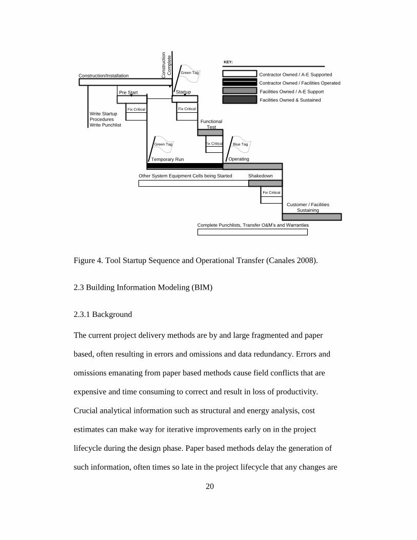
2.2.2.3 System Commissioning and Start-up
System commissioning and start-up begins by writing start-up procedures and
punchlists to fix critical issues to facilitate a soft start-up of the tool during the
construction and installation phase. The system is then green tagged and tested for
function during a temporary run and critical issues are fixed. The system is then
blue tagged and operated along with other equipment being started. During the
final shakedown, critical issues are fixed and the tools are handed over to the
facility owners/operators. Figure 4 below shows the tool start-up sequence and
operational transfer (Canales 2008).
20
Construction/Installation
Pre Start
Fix Critical
Startup
Operating
Shakedown
Customer / Facilities
Sustaining
Contractor Owned / A-E Supported
Contractor Owned / Facilities Operated
Facilities Owned / A-E Support
Facilities Owned & Sustained
Complete Punchlists, Transfer O&M’s and Warranties
Co
nstr
uctio
n
Co
mp
lete
Fix Critical Fix Critical
Write Startup
Procedures
Write PunchlistFunctional
Test
Fix Critical
Green Tag
Green Tag Blue Tag
Other System Equipment Cells being Started
Temporary Run
KEY:
Figure 4. Tool Startup Sequence and Operational Transfer (Canales 2008).
2.3 Building Information Modeling (BIM)
2.3.1 Background
The current project delivery methods are by and large fragmented and paper
based, often resulting in errors and omissions and data redundancy. Errors and
omissions emanating from paper based methods cause field conflicts that are
expensive and time consuming to correct and result in loss of productivity.
Crucial analytical information such as structural and energy analysis, cost
estimates can make way for iterative improvements early on in the project
lifecycle during the design phase. Paper based methods delay the generation of
such information, often times so late in the project lifecycle that any changes are

21
expensive to make and value engineering could compromise the original design
(Eastman et al. 2008).
Project Time
Le
ve
l o
f In
flu
en
ce
on
Co
st
Start
0%
100% Ability to influence
costs
Construction cost100%
0%
Figure 5. Time versus Ability to Impact Cost
2.3.2 Challenges of Traditional Approaches
The CIFE (Centre for Integrated Facility Engineering, Stanford University) study
of construction industry labor productivity indicates that productivity of the
construction industry relative to all non-farm industries over a forty year period,
from 1964 through 2004 has steadily declined (see Figure 6) (Teicholz 2001).
Efficiencies achieved in the manufacturing industry through automation, the use
of information systems, better supply chain management and improved
collaboration tools, have not yet been achieved in the field of construction.
Reasons for this include the size of construction firms, inflation adjusted wages of
construction workers has stagnated over the past 40 years discouraging the need

22
for labor saving innovations. The adoption of new and improved business
practices in both design and construction has been slow and limited to large firms.
Often times it remains necessary to revert back to paper or 2D CAD drawings so
that all members of the project team are able to communicate with each other.
Figure 6. Indexes of Labor Productivity (Teicholz 2001)
The NIST (National Institute for Standards and Technology) study of the
additional cost incurred by building owners as a result of inadequate
interoperability indicates that insufficient interoperability accounts for an increase
in construction costs by $6.12 per sf for new construction and an increase in $0.23
per SF for operations and maintenance (O&M), resulting in a total added cost of
$15.8 billion. The study involved both the exchange and management of

23
information, in which individual systems were unable to access and use the
information imported from other systems. It was determined that additional costs
associated with redundant computer systems, inefficient business process
management, manual reentry of data, inefficient RFI (Request for Information)
management can be attributed to insufficient interoperability and resulted in
increases in project costs. It is estimated that 68% of these additional expenses
($10.6 billion) were incurred by building owners and operators (Eastman et al.
2008). Adoption of Building Information Modeling by all the stakeholders in the
project lifecycle can help reduce costs associated with inadequate interoperability
of data.
2.3.3 Building Information Modeling- Definition
Building information modeling may be defined as a modeling technology and the
associated set of processes to produce, communicate and analyze building models.
Building models are characterized by
Building components that are represented with intelligent digital
representations that can be associated with computable graphic and data
attributes and parametric rules.
Components that include data that describe how they behave as needed for
analyses and work processes, e.g takeoff, specification and energy
analyses.

24
Consistent and non redundant data such that changes to component data
are represented in all views of the component.
Coordinated data such that all views of a model are represented in a
coordinated way (Eastman et al. 2008).
A Building Information Model may or may not have geometry or information
depending on the requirements at that particular stage of the project and the 3D
CAD model or information can still be a BIM. Many BIM building projects do
not start with a model made by a CAD system but with information about a
client‘s requirements. This collection of information is also a BIM and can be
later fed into a BIM authoring tool. Building information modeling benefits all the
stakeholders throughout the project lifecycle. It adds pre-construction benefits to
the owner, design benefits to the architects and engineers, construction and
fabrication benefits to the builders and post construction benefits to the owner
operators. The detailed benefits at the various stages of the project to the various
stakeholders are described as follows.
2.3.4 Pre-Construction and Post-Construction Benefits to Owner
Owners and operators of facilities can derive enumerable benefits from initiating,
funding and maintaining Building Information Models. Building Information
Models help owners increase the value of their buildings by facilitating energy
design and analysis earlier on in the project. Building Information Models can
help shorten project duration by providing opportunities to coordinate the design
25
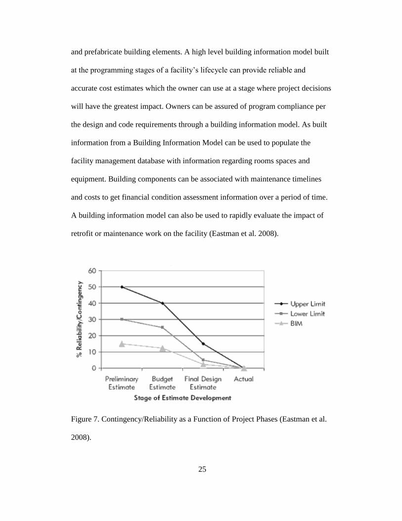
and prefabricate building elements. A high level building information model built
at the programming stages of a facility‘s lifecycle can provide reliable and
accurate cost estimates which the owner can use at a stage where project decisions
will have the greatest impact. Owners can be assured of program compliance per
the design and code requirements through a building information model. As built
information from a Building Information Model can be used to populate the
facility management database with information regarding rooms spaces and
equipment. Building components can be associated with maintenance timelines
and costs to get financial condition assessment information over a period of time.
A building information model can also be used to rapidly evaluate the impact of
retrofit or maintenance work on the facility (Eastman et al. 2008).
Figure 7. Contingency/Reliability as a Function of Project Phases (Eastman et al.
2008).

26
2.3.5 Design Benefits to Architects and Engineers
Building information modeling can benefit all stages of the design process from
the conceptual and schematic design phase to producing construction documents
for review. The schematic design phase shows the design of the programmatic
requirements, massing of the building, possible materials and finishes and types
of building systems and subsystems. The design development phase develops
generic details for the structure, walls, facades and MEP (Mechanical, Electrical
and Plumbing) systems. The construction detailing phase shows detailed plans for
demolition, site preparation, and detailed specification of building systems, sizing
and connection of components. The construction review phase facilitates
coordination between details and as built conditions. Building information
modeling helps in redistributing the effort from the later stages of design to the
earlier stages of design where changes to design have a higher ability to impact
cost (see Figure 8) (Eastman et al. 2008).

27
1
2
3
4
Ability to impact cost and functional capabilities
Cost of design changes
Traditional design process
Preferred design process
PD: Pre Design
SD: Schematic Design
DD: Design Development
PR: Procurement
CA: Construction Administration
OP: Operation
Figure 8. Value Added, Cost of Changes and Current Compensation Distribution
for Design Services (Eastman et al. 2008).
At the conceptual design phase a building information model provides checks for
siting, massing and a visual feel for fitting and locating the programmatic
requirements within the building. At the detailed design phase BIM is used for the
design and analysis of the building systems. Various design and modeling
software can help in analyzing a building‘s structure, temperature, lighting,

28
acoustics and energy consumption. The information contained within a building
information model not only aids in analyzing a particular aspect of the design but
can facilitate cross discipline design iterations to produce the most efficient
design. Building information models can expedite the process of creating
construction documents for the construction document phase. Placement and
composition rules within a BIM software can help standardize and expedite the
production of construction documents. During the final phases of design
development the BIM aids in the integration of the design and construction. In a
design-build delivery process it can expedite design iterations that help in
developing a design favorable for a faster and more efficient construction process
(Eastman et al. 2008).
2.3.6 Construction Benefits to Contractors
A building information model offers many benefits to developers and contractors
during the construction phase. A building information model can be used to
reduce design errors by using clash detection. After the design phase and just
prior to construction models containing construction details from various
subcontractors can be merged to detect any conflicts between the various building
systems such as clashes between MEP systems, and structure and MEP. BIM
software that helps in clash detection not only facilitates automatic geometry
clash detection but also allows semantic and rule based conflict analyses that

29
allow for identifying interferences based on proximity and systems (Eastman et al.
2008).
Figure 9. Snapshot of a Contractor and Subcontractor using BIM to Support MEP
Coordination (Eastman et al. 2008).
A building information model can assist in quantity takeoff and cost estimation.
Counts of building components, linear footages of pipes, areas of surfaces and
volumes of spaces can be extracted from a model and associated with costs to
produce project estimates. A building information model linked to a schedule can
simulate the construction process. A time based simulation provides better insight
into the construction sequence, detects time based interferences, help in better
trade sequencing and improves site logistics by optimizing crane layouts, laydown
areas, location of large equipment and office trailers.

30
Figure 10. 4D view of Construction of Vancouver Convention Center showing
Foundation and Structural Steel Erection (Eastman et al. 2008).
A Building Information Model can also be integrated with cost and schedule
control and other management functions. Building components in a BIM can be
provided with ‗status‘ as a property which can be then associated with colors to
quickly be able to identify areas behind schedule. Objects in a BIM can be used to
quickly populate a procurement database. Some applications (like 1st pricing)
allow procurement within BIM applications, providing direct quotes to
components such as doors and windows based on zip code. An accurate building
31
information model can readily and accurately facilitate offsite fabrication. A BIM
can transfer geometrical, dimensional as well as finish information from a
subcontractor‘s detailer directly to the fabricator, reducing the need to recreate the
information and at the same time reducing errors during data transfer. BIM can
also be used for onsite verification, guidance and tracking of construction
activities. Laser scanning technologies that report into a BIM tool can help verify
locations of building systems for critical pours. Dimensions from a BIM tool can
be used to guide machines that excavate and grade earthwork. GPS technologies
can be linked to a BIM to verify layout locations. BIM components that reference
RFID tags can be used to track delivery and installation of the components offsite
(Eastman et al. 2008).
2.3.7 Building Information Modeling Benefits for Subcontractors and Fabricators
The benefits of BIM for Subcontractors and fabricators include:
Enhanced marketing and rendering through visual images and automated
estimating
Reduced cycle times for detailed design and production
Elimination of all design coordination errors
Rendering through visual images (see Figure 11)
Automated estimating
Reduced cycle time for detailed design and production
Elimination of almost all design coordination errors

32
Lower engineering and detailing costs
Data to drive automated manufacturing technologies
Improved preassembly and pre fabrication.
Figure 11. Improved Visualization – Moving from paper based methods to digital
3D models (Eastman et al. 2008).
2.3.8 Parametric Modeling
Crucial to the understanding of BIM are the concepts of Parametric modeling and
Interoperability.
A parametric model may be defined as
Consisting of geometric definitions and associated data and rules.
Integrating geometry non redundantly
Modifying associated geometries when inserted into a building model
through parametric rules.
Defining objects at different levels of aggregation and hierarchy.
Receiving, broadcasting and exporting sets of object attributes (Eastman et
al. 2008).
33
2.4 Interoperability
Interoperability is a property referring to the ability of diverse systems to work
together. Various stakeholders in the lifecycle of a building facility, based on the
specialty, use different softwares for documentation, design, construction and
operations. During the various phases of the lifecycle of a project, different kinds
of information are used, generated and handed over from one stakeholder to
another, oftentimes using different software applications. During the design phase
architects and engineers use various design and analysis softwares such as
AutoCAD or Bentley Microstation. During the construction phase project
managers use various scheduling, estimation and project management software
such as Prolog, Timberline and Primavera Project Planner. Ability to transfer
information between these various phases and applications is minimal and
oftentimes requires manual reentry.
Software interoperability is seamless data exchange at the software level among
diverse applications, each of which may have its own internal data structure
(NIBS 2007). Data can be exchanged between two applications either through
direct, proprietary links between the two applications or through proprietary file
exchange formats that deal with geometry or through public product data model
exchange formats or XML-based exchange formats.
Direct links provide an integrated connection between two applications through
programming level interfaces that make part or the whole of the building model

34
accessible to the other application accessible for creation, export, modification or
deletion.
A proprietary exchange format is developed by a particular company to interface
with a particular application. An exchange format is usually implemented as a file
in human readable text format. A popular AEC exchange format is the DXF (Data
eXchange Format) defined by Autodesk.
The public exchange formats utilize open building standards such as the IFC
(Industry Foundation Classes). Some of these public exchange formats apart from
geometry also carry object, material properties and the relations between them
(Eastman et al. 2008). Some softwares prefer to use the direct link to exchange
information between them because the exchange of information is more robust.
Based on the functionality the type and kind of information to be exchanged is
agreed upon and the transfer mechanism is developed, debugged and maintained
by the authors of the application (Eastman et al. 2008).
Open industry standards on the other hand are built and maintained by a
consortium of industry people representing the various stakeholders who build,
maintain, buy and use the applications. Construction projects involve several
designers, contractors and subcontractors who utilize various applications to
provide services contracted to them. Mapping the applications data to the open
industry data standards allows the application to be interoperable with other

35
applications mapped to the same open industry standard. This kind of
interoperability allows several applications to exchange information among each
other with a single mapping versus several mappings in a direct link (Eastman et
al. 2008).
Overcoming data transferability issues is key to fully interoperable integrated
project delivery system. In order for a real free flow of information to occur, three
factors need to be in place (see Figure 12):
The format for information exchange – Digital Storage
A specification of which information to exchange and when to exchange
the information - Process
A standardized understanding of what the information exchanged actually
is – Terminology
Figure 12. Interoperability through Standards (Grant 2008)

36
Having these three fundamental items in place allows for a true computerized
interoperability between two or more information parties. This approach has been
used with success in other industries, most notably the oil and gas industry, to
support application and data interoperability.
Several organizations such as the International Alliance for Interoperability (IAI),
EPISTLE (European Process Industries STEP Technical Liaison Executive),
National Institute for Building Sciences (NIBS), Facility Information Council
(FIC) have been creating data standards for various industries and geographical
locations. SEMI (Semiconductor Materials and Equipment International) has been
developing data standards for the Semiconductor Manufacturing Industry.
2.4.1 Industry Foundation Classes (IFC)
The Industry Foundation classes are a neutral data format that describes
information used within the building and facility management industry. It
facilitates the exchange and sharing of information between the different
applications used by the various stakeholders in the lifecycle of the facility
(buildingSMART 2011a). The IFC specification is developed and maintained by
buildingSMART Alliance (formerly the International Alliance for
Interoperability). buildingSMART Alliance is an organization of representatives
from AEC firms, Owners, Suppliers and Software providers. It facilitates the
development and deployment of open standards for the building industry
37
worldwide via local chapters. Specifications such as the International Framework
for Dictionaries (IFD) and Information Delivery Manual (IDM) are being
developed parallel to the IFC and complement it. The Information Delivery
Manual (IDM) aims to identify the processes within the building industry and the
information that is needed and generated from these processes. The IDM details
the IFC capabilities that need to be supported for each process in terms of the
entities, attributes, property sets and properties required (buildingSMART 2011b).
The IFD (International Framework for Dictionaries) is a library with terminology
and ontologies assisting in identifying the type of information being exchanged.
The IFD supports the IFC by providing a dictionary that describes the objects and
specifying what properties, values and units they can have (buildingSMART
2011c). Together the IFC, IDM and IFD provide a comprehensive mechanism for
digital storage, specification of terminology and description of the process for
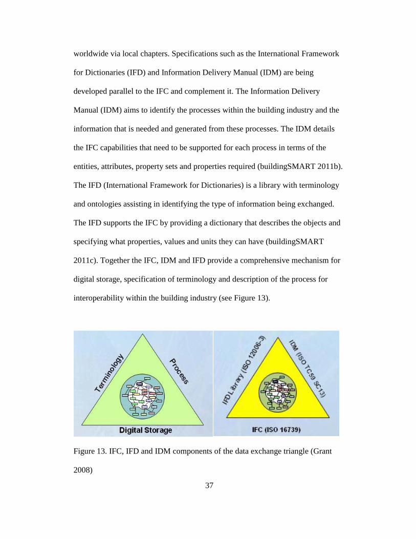
interoperability within the building industry (see Figure 13).
Figure 13. IFC, IFD and IDM components of the data exchange triangle (Grant
2008)

38
2.4.1.1 History of IFC
Autodesk in 1994 invited a consortium of industry participants to advise the
company on C++ classes to facilitate integrated product development. It was
called the Industry Alliance for Interoperability. Initially comprised of 12 industry
participants this consortium opened its doors to all interested industry
participants. In 1997 it was renamed the International Alliance for Interoperability
and it reconstituted itself as a non-profit industry led organization with the goal of
developing the Industry Foundation Classes (IFC) – a neutral data format for the
building industry (Eastman et al. 2008). In 2005 the IAI again reorganized itself
as the buildingSMART Alliance and has continually developed and maintained
the IFCs.
The development of the IFC is an international effort with chapters in several
countries. All chapters can participate in any of the domain committees. Domain
committees address each area of expertise such as Architecture, Construction and
Codes and Standards. The International Council Executive committee is the
overall lead organization in the IAI. The North American Chapter is administered
by the National Institute of Building Science in Washington DC.
The IFC specification is written using the EXPRESS data definition language.
IFC defines multiple file formats such as IFC-SPF, IFC-XML and IFC-ZIP. IFC-
SPF is the most widely used IFC format. It is a text format defined by ISO 10303-
21 (STEP). IFC-XML is an XML format defined by ISO 10303-28 (STEP-XML).
It is interoperable with XML tools. IFC-ZIP is a compressed format for an IFC-

39
SPF file. Several versions of the IFCs have been released over the years. The first
version IFC 1.0 was released in 1997. The latest version of the IFC - IFC 2x4 was
released in September 2010.
2.4.1.2 IFC Architecture
The overall structure of the IFC is comprised of 4 main layers; the resource layer,
the core layer, the interoperability layer and domain layer (see Figure 14). Each
layer consists of several categories or schema. For example the wall entity falls in
the Shared Building Elements Schema which is a part of the Interoperability layer
(Khemlani 2004).
The resource layer consists of categories of entities representing basic properties
such as geometry, material, cost etc. They are generic entities that are used to
describe categories in the upper layers (Khemlani 2004).
The core layer consists of entities that represent abstract concepts that can be used
to define entities in higher layers. The kernel schema defines core concepts such
as actor, group, product, process and relationship which may be used to describe
higher level entities in upper layers. The product extension schema defines
abstract building components such as space, site, building, building element,
annotation etc. The process schema describes tasks, events and procedures. The
control schema captures rules controlling time and cost (Khemlani 2004).

40
The Interoperability layer consists of common building elements shared between
building construction and facilities management applications. The shared building
elements schema has entities such as beam, column, wall etc. The Shared
Building Services schema has entities such as flow controller, flow segment,
sound properties etc. The shared Facilities Elements Schema has entities such as
furniture, occupant and asset (Khemlani 2004).
The Domain Layer is the highest level in the IFC model and contains entities for
individual domains such as Architecture, structural elements, HVAC etc. For
example boilers and chillers are entities in the HVAC schema.
Figure 14 shows the overall structure of the IFC Architecture.

41
Managemetn
Control
Extension
Shared Bldg
Services
Elements
Shared
Management
Elements
Shared
Facilities
Elements
Shared
Building
Elements
Shared
Component
Elements
Process
Extension
Product
Extension
Kernel
HVAC Domain
Structural
Analysis
Domain
Structural
Elements
Domain
Building
Controls
Domain
Plumbing Fire
Protection
Domain
Architecture
Domain
Construction
Management
Domain
Facilities Mgmt
Domain
Electrical
Domain
IFCx2 platform –
IFC2x part equal to
ISO/PAS 16739
Non-platform part
Domain
Layer
Interoperability
Layer
Core Layer
Resource Layer
Actor
Resource
Material
Property
Resource
Measure
Resource
Material
Resource
Geometry
Resource
Geometric
Model
Resource
Geometric
Constraint
Resource
External
Reference
Resource
DateTime
Resource
Cost
Resource
Utility
Resource
Topology
Resource
Respresen
tation
Resource
Quantity
Resource
Property
Resource
Profile
Resource
Approval
Resource
Constraint
Resource
Time Series
Resource
Presentation
REsource
Presentation
Organization
Respource
Presentation
Definition
Resource
Presentation
Appearance
Resource
Presentation
Dimension
Resource
Profile
Property
Resource
Structural
Load
Resource
Figure 14. IFC Architecture – IFC 2x3 (Khemlani 2004)
Certain elements in the IFC model make flexible as well as extensible. Property
sets are generic sets of properties that may be used to describe one or more
entities. Any property that is specific to an entity becomes an attribute of that
entity. Properties that can be used to describe various entities are collected as
property sets. Several omissions to the property sets can be identified (Eastman et
al. 2008). The IFC provides a mechanism called proxies for software makers to
42
create new entities with attributes for entities not described in the IFC model. For
example architectural elements present in a particular geographical location (such
as perforated screens) can be defined in local IFC implementations in those
countries as a proxy (Khemlani 2004).
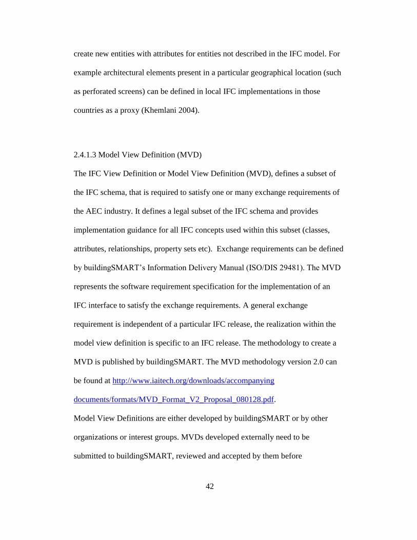
2.4.1.3 Model View Definition (MVD)
The IFC View Definition or Model View Definition (MVD), defines a subset of
the IFC schema, that is required to satisfy one or many exchange requirements of
the AEC industry. It defines a legal subset of the IFC schema and provides
implementation guidance for all IFC concepts used within this subset (classes,
attributes, relationships, property sets etc). Exchange requirements can be defined
by buildingSMART‘s Information Delivery Manual (ISO/DIS 29481). The MVD
represents the software requirement specification for the implementation of an
IFC interface to satisfy the exchange requirements. A general exchange
requirement is independent of a particular IFC release, the realization within the
model view definition is specific to an IFC release. The methodology to create a
MVD is published by buildingSMART. The MVD methodology version 2.0 can
be found at http://www.iaitech.org/downloads/accompanying
documents/formats/MVD_Format_V2_Proposal_080128.pdf.
Model View Definitions are either developed by buildingSMART or by other
organizations or interest groups. MVDs developed externally need to be
submitted to buildingSMART, reviewed and accepted by them before

43
implementation. The process to use externally developed MVDs is currently
being developed by buildingSMART (buildingSMART 2011d).
2.4.2 Information Delivery Manual (IDM)
Building Information Modeling brings together diverse sets of information used
and generated by all the stakeholders in a building‘s lifecycle. For the Building
Information Model to be fully beneficial the quality of communication between
the various participants needs to be improved. It is important to clearly define and
agree upon the various processes in the building lifecycle and the information that
is used and results from their execution.
The Information Delivery Manual (IDM) aims to identify the processes within the
building industry and the information that is needed and generated from these
processes. The IDM details the IFC capabilities that need to be supported for each
process in terms of the entities, attributes, property sets and properties required.
To the BIM user the IDM provides a description of the building construction
processes and the information that needs to be provided for the processes to be
successful. For solution providers the IDM also details the IFC capabilities that
need to be supported for each process in terms of the entities, attributes, property
sets and properties required. IDM methods for defining business process and
specifying information exchange requirements are independent of any information
model. However IDM also has technical solution components that do use specific

44
information models. For building construction, it uses the capabilities of the IFC
model and the extended property definitions declared in the IFD dictionary (Wix
2008).
2.4.2.1 IDM Architecture
The Information Delivery Manual proposes a methodology for the development
of process maps, exchange requirements, functional parts, business rules and
verification tests for a business process. Process maps describe the flow of
activities for a particular business process. They provide an understanding of the
configuration of activities that make the work, the actors involved, the
information required, consumed and produced. An exchange requirement is a set
of information that needs to be exchanged to support a particular business
requirement at a particular stage of a project. It provides a description of the
information in Non-Technical terms. A functional part is a unit of information or
a single information idea used by solution providers to support an exchange
requirement. It is a complete schema in its own right as well as being a subset of
the full standard on which it is based. Business rules are constraints that may be
applied to a set of data used within a particular process. It is used to vary the
result of using a schema without having to change the schema itself; for example
localizing an international standard. Verification tests are testing software that
verifies the accuracy of the support for exchange requirements.

45
IDM is closely associated with Model View Definitions (MVD) in the IFC. IDM
is a formal description of the business processes and MVD is how this is
implemented in software using the IFC. A detailed description of the
methodology and format for the IDM is described in the ISO standard ISO 29481
– 1:2010 Building Information Modeling – Information Delivery Manual – Part 1
Methodology and Format (Wix 2008).
Figure 15. IDM – Architecture (Wix 2008)
2.4.3 International Framework for Dictionaries (IFD)
The IFD (International Framework for Dictionaries) is a library with terminology
and ontologies assisting in identifying the type of information being exchanged.
The IFD supports the IFC by providing a dictionary that describes the objects and
specifying what properties, values and units they can have (buildingSMART 2011
c).

46
2.4.3.1 History of IFD
The need for a standardized global terminology with a structure that would be
useful for computers to reliably exchange data prompted the development of the
ISO 12006-3. The ISO 12006-3 – Framework for object –Oriented Information
Exchange was developed by the ISO Committee TC59/SC13/WG6. Upon
publication of the standard STABU LexiCon in Holland and BARBi in Norway
developed their object library databases to be compatible with the standard. The
organizations combined their effort in 2006 through an agreement to produce a
single object library/ontology called the International Framework for Dictionaries
(IFD). In 2006 the Construction specifications Institute, construction
Specifications Canada, building SMART Norway and the STABU Foundation
signed a Letter of intent to share unified object libraries developed under ISO
12006-3 as a structure for a controlled dictionary of construction terminology.
This group eventually joined the buildingSMART International organization with
the objective to manage and develop an open, international and multilingual IFD
library based on the principles of ISO 12003-3 2007.
2.4.3.2 Relationship between the IFC and IFD
The IFD is an open library which consists of definitions of concepts. These
concepts are given a unique identification number (Globally Unique Id GUID).
The IFC would utilize the concepts defined in the IFD to make the information
exchanged understandable. When a material is specified by the engineer in French
the supplier can understand the material in Chinese. The GUID of the material

47
specified enables the computer to understand that the material is the same but is
presented in different languages. The IFD also has provisions for expressing
synonyms, plurals etc. The IFC now uses its own definitions stored in the model
and property sets. These definitions will be mapped to the corresponding
definitions in IFD (Grant 2008).
2.4.3.2 IFD Library
IFD library is being developed in two streams; the content and technology.
Content in the IFD is of two types; Concept and Characteristics. A concept is a
thing that can be distinguished from other things. A concept may have several
labels or one name can be used as a label for several concepts. All concepts are
assigned a Globally Unique Id. Characteristics or properties are concepts that are
described using a description. Characteristics are concepts that cannot be defined
using other concepts. Subjects are concepts being defined and characteristics are
concepts that define. Characteristics contain values when instantiated in a
relationship (IFD 2008). Concepts are related to other concepts through
relationships. Relationships are collected into contexts based on how and where
they came from. Concepts can relate to other concepts in multiple contexts. Figure
16 is an example of how a door may be used in multiple contexts.
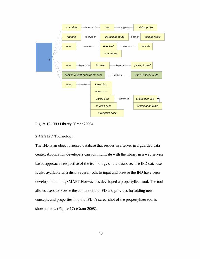
48
inner door
firedoor
door
door
horizontal light-opening for door
door
doorway
inner door
outer door
sliding door
rotating door
strongarm door
door frame
door leaf
fire escape route
door building project
opening in wall
with of escape route
sliding door leaf
sliding door frame
door sill
escape route
is a type of
is a type of
consists of
is part of
can be
consists of
relates to
is part of
consists of
is a type of
is part of
Figure 16. IFD Library (Grant 2008).
2.4.3.3 IFD Technology
The IFD is an object oriented database that resides in a server in a guarded data
center. Application developers can communicate with the library in a web service
based approach irrespective of the technology of the database. The IFD database
is also available on a disk. Several tools to input and browse the IFD have been
developed. buildingSMART Norway has developed a propertylizer tool. The tool
allows users to browse the content of the IFD and provides for adding new
concepts and properties into the IFD. A screenshot of the propertylizer tool is
shown below (Figure 17) (Grant 2008).

49
Figure 17. buildingSMART Propertylizer Tool (Grant 2008)
2.4.4 ISO 15926 - "Industrial automation systems and integration‖
The ISO 15926 is titled: "Industrial automation systems and integration—
Integration of life-cycle data for process plants including oil and gas production
facilities". ISO 15926 is a standard for data integration, sharing, exchange, and
hand-over between computer systems. The ISO 15926 facilitates data exchange
between conforming applications by providing a standardized understanding of
the data, providing templates for the organization of data and neutral format for
data exchange (see Figure 18).

50
Figure 18. ISO15926 Components of the Data Exchange Triangle
When two organizations want to exchange information through the ISO 15926,
they map the data structure of their internal applications to the ISO 15926. The
Part 2 – Data Model of the standard specifies the format for the information
exchange, Part 4 – Reference Data Library provides a standardized understanding
to the terms. The RDL is implemented in a Reference Data System/Work in
progress RDS/WIP. The two organizations map their internal applications to ISO
15926 using the classes and definitions in RDS/WIP. When data is exchanged
between the two applications they refer to the RDL at the beginning (export) and
end of the exchange (import). Since the ISO 15926 is used at the edges of the
process of data transfer, it is considered external to the organization, as in both the
applications exchanging information need not change their internal structure nor
expose it to the business partner. It allows each application to only share the
information that they need or want to share (Rachar 2009a).

51
2.4.4.1 History of ISO 15926
In 1991 a consortium of companies in the European Union came together for a
research project called ProcessBase. The objective of the project was to develop a
data model for lifecycle information of facilities in the process industries. This
consortium later on came to be known as EPISTLE – European Process Industries
STEP Technical Liaison Executive. From a consortium of companies involved
with the process industries the EPISTLE evolved into a consortium of national
organizations predominantly from the European Union PISTEP (UK),
POSC/Caesar (Norway), and USPI-NL (Netherlands).
EPISTLE developed the Annex M of the ISO 10303-221 commonly referred to as
the AP 221. Annex M consisted of a list of standard instances of the AP221 data
model. These standard instances were to act as a knowledge base for the types of
objects. EPISTLE further extended the Annex M as a library of object classes and
the relationships called STEPlib. Due to modelling/technical reasons
POSC/Caesar proposed another standard ISO 15926 instead of ISO 10303. The
core data model developed by EPISTLE was adopted and developed as Part 2 of
ISO 15926. POSC/Caesar started making its own library of classes (RDL –
Reference Data Library) by adding special classes such as ANSI pipe and pipe
fittings. The core classes of the two libraries; STEPlib and EPISTLE were merged
to form Part 4 of the ISO 15926. The ISO 15926 is currently being supported by
FIATECH (Fully Integrated and Automated Technology) and POSC/Caesar.
FIATECH is a North American Organization whose goal is to develop and

52
propagate technology to increase productivity in the capital projects industry. ISO
15926 is managed by the Technical Committee 184, Subcommittee 4
(TC184/SC4) of the International Standards Organization (ISO). The ISO 15926
consists of 11 parts. Parts 1, 2, 3 and 4 have been turned over to the ISO and the
remaining parts are in development.
How we Store and
Exchange Textual
information
Markup
Language
ISO 15926
ISO 15926-4
How we store and
exchange Plant
Information
Interoperability
Projects
How we use the
internet to find
information
The Semantic
Web
How we know and
understand things
Ontologies
STEP
POSC/
CAESAR
Project
FIATECH
2000
1999
1984
Figure 19. History of ISO 15926 (Rachar 2009b).
2.4.4.2 ISO 15926 Parts
The ISO 15926 consists of 11 parts. Some of these parts are completed and have
been turned over to the ISO and others are under development.

53
Figure 20. Parts of ISO 15926 (Rachar 2009c).
Part 1 – Overview and Principles - Part 1 of the ISO 15926 was published by the
ISO in 2004. The ISO 15926-1:2003 specifies a representation of information
associated with engineering construction and operation of process plants. This
representation supports the information requirements of the process industries in
all phases of a plant‘s life-cycle and the sharing and integration of information
amongst all parties involved in the plant‘s life cycle (ISO 15926 2003).
Part 2 – Data Model. The data model is based on the EPISTLE Core Model. It
consists of entities and relationships; the relationships being the constraints. Part 2
was published by the ISO in 2003 (Rachar 2009c).
54
Part-3 – Reference data for geometry and topology. This part is used to represent
3D CAD objects and systems. Part 3 is still under development and has not been
published by the ISO (Rachar 2009c).
Parts 4, 5, and 6 - Reference Data – Part 4 is like a dictionary or a thesaurus. It
provides definition of the entities and their taxonomy through parent child
relationships. Part 4 was published by ISO in 2007. Part 5 - Describes procedures
for registration and maintenance of reference data. Part -6 - RDS WIP (Rachar
2009c).
Part 7 – Templates "Implementation Methods for the Integration of Distributed
Systems Templates Methodology." Templates are smaller implementation models
of Part 2. It is like a spreadsheet with rows and columns. The column headers in
the spreadsheet are the "roles" of the template. Each row of the spreadsheet is a
template instance. Each cell in the row is a value of a role (the column heading).
A template definition is the generic spreadsheet itself - it defines the name of the
template, and the roles and what types of information are valid in those roles.
Figure below shows a model of a template (Rachar 2009c).

55
Figure 21. Example of Template (Rachar 2009c)
Part 8 – RDF/OWL Implementation Specification. OWL or Web Ontology
Language is a method of creating an ontology expressed in RDF syntax. RDF or
Resource Description Framework is a way of making statements about things.
ISO 15926 Part 8 involves standardization of the implementation of ISO15926
Part 7 templates using RDF and OWL (Rachar 2009c).
Part 9, 10 and 11 – Facade Specification. Part 9 enables applications to
communicate with each other over the internet through a façade. Part 9 provides a
specification for the standardization of the web service using SPARQL for a
façade. A façade provides an outward facing view of things. External
applications communicate with a source application by querying its façade.
Facades enable an application to selectively share information. Part 10 provides
for abstract test methods and Part 11provides for a Gellish Implementation using
reference data (Rachar 2009c).

56
2.4.4.3 Deployment of ISO 15926
The ISO 15926 is currently being developed as a collaborative effort by POSC
Caesar and FIATECH through a series of smaller projects collectively called IDS-
ADI (POSC Caesar IDS – Intelligent Data Sets and FIATECH ADI – Advanced
Deployment of ISO 15926). Significant projects that have helped develop and
advance the ISO 15926 are the Proteus, Camelot and Avalon Projects.
The Proteus project showed transfer of information between different P&ID
systems, P&ID systems and 3D systems and between 3D systems using the
ISO15926. The three types of information flows are typical during the handover
of the project from EPC to owner. This project demonstrated the lowest level of
ISO 15926 compliance; Dictionary level – ―Any XML file schema containing
RDS/WIP class names‖ (Rachar 2009d)
The Camelot project implemented the full specification of ISO15926 (Part 2, 4, 7,
8 and 9) and demonstrated transfer of information between various organizations
in real time using web services. iRING (ISO 15926 Real time Interoperability
Network Grid) – a web based technology suite that helps deploy ISO15926 was
developed. Data that needed to be transferred from commercial or proprietary
software was converted using the iRing adapter and transmitted to the target
location using the iRING web services and imported into the receiving application
using the iRING adapter (Rachar 2009d).

57
2.4.4.4 The ISO 15926 Real-time Interoperability Network Grid - iRING
iRING is a web based implementation of the ISO 15926. It is open sources and is
developed using .net and Java. It facilitates interoperability between applications
through the ISO 15926. It provides a medium to define and exchange information
real time through web based services. Companies can use it to exchange
information both internally and externally by mapping their data structures to the
ISO 15926 using the iRING (IDS-ADI 2011).
The iRING provides components that facilitate browsing and publishing classes to
the Reference Data Library (RDL), templates for modeling relationships, facades
that enable exchange of information and a mapping editor that enables mapping
legacy data to ISO 15926 (IDS-ADI 2011).
The key components of the iRING that facilitate data transfer are:
RDS/WIP
RDS/WIP browsers and editors
Sandbox(es)
iRING Mapping Editor
The Reference Data System/Work in Progress (RDS/WIP) is used to publish
definitions in ISO 15926. It is a library based on OWL/RDF and uses SPARQL
for querying the data. It is extensible and is therefore refered to as Work In
Progress (WIP) (IDS-ADI 2011).

58
The RDS/WIP Editor enables users to browse the ISO 15926 and add new classes
through the sandboxes. The sandbox is a database that enables users to add to the
ISO 15926. Data is a sandbox is not permanent and needs to go through several
approvals to the moved to the RDS/WIP (IDS-ADI 2011).
The mapping editor facilitates mapping of source schema to the ISO 15926 data
in the RDS/WIP. The current iRING version 1.0 provides for mapping legacy data
schema to ISO 15926, transforming information into ISO15926 data and proto
facades that help in exchanging information between endpoints through the
internet (iRING 2011). Reference data repositories (Figure 22); a concept to be
implemented in future iRING versions will provide the infrastructure to add
classes. The reference data repository will consist of private, community and
global sandboxes. Each of these sandboxes is different in terms of access modes
and source. A community sandbox can have one or more participants with
community managed read-only and read write access. The content in a
community sandbox is considered volatile. The volatility is managed by the
community. Content can be moved from the community sandbox to the global
sandbox through an approval process. Once content reaches the global sandbox it
becomes immutable (IDS-ADI 2011).

59
Figure 22. Reference Data Federation (IDS-ADI 2011).
2.4.5 Other Data Standards – STEP, IGES
STEP which stands for ‗Standard for the Exchange of Product Model Data‘ is an
ISO standard ISO10303 for the computer interpretable representation and
exchange of product manufacturing information. The goal of STEP is to develop a
reliable and universal system of transferring data. The STEP covers geometry,
topology, relationships attributes, assemblies, configuration and more to represent
the product‘s entire life-cycle.
STEP is built on EXPRESS language that can formally describe the structure of
any engineering information. STEP is an international product modeling standard
used in the manufacturing and the defense industries, and can extend to any
60
industry. IFC adopts the EXPRESS language and the Building Construction Core
Model from STEP.
The IGES specification; pioneered by the mechanical CAD/CAM industry is a
neutral file format that specifies both geometric and non geometric entities.
Geometric entities represent the definition of the physical shape and include
points, curves, surfaces and relations which are collections of similarly structured
entities. Non geometric drawings typically serve to enrich the model with
annotations and dimensioning.
2.4.6 SEMI Standards for Semiconductor Manufacturing Facilities
2.4.6.1 SEMI E6 – Guide for Semiconductor Equipment Installation
Documentation
Semiconductor Equipment and Materials International (SEMI) developed the
SEMI E6 as a guide for all the stakeholders from equipment suppliers and facility
designers to equipment installers and facility operators for communicating in a
standardized way, the information necessary to prepare the facility and to
efficiently install semiconductor equipment. It consists of a series of data sheets
that address all information related to the identification, environmental conditions,
physical characteristics and utility connections on the equipment. Data sheets for
utility connections include electrical power, water, bulk chemicals, drains, gases,
vacuum and exhaust. Table 1 below shows the various data sheets in the SEMI
E6.

61
Table 1. SEMI E6 Data Sheet Table (SEMI 2003). Republished with permission
from Semiconductor Equipment and Materials International, Inc. SEMI © 2011.
Data Sheet Number Data Sheet Title
100 Equipment Identification
200 Environmental Conditions
300 Physical Characteristics
400 Electrical Power
500 Water
600 Bulk Chemicals
700 Drains
800 Gases
900 Vacuum
1000 Exhaust
The SEMI E6 datasheets are defined and organized into tables with various
attributes or related information. Table 2 below shows the equipment
identification data sheet (Series 100). The SEMI E6 document showing all data
sheets with the information that is to be input to complete the data sheet is
attached as Appendix A to this document.
Table 2. SEMI E51 – Series 100 - Equipment Identification Data Sheet (SEMI
2003). Republished with permission from Semiconductor Equipment and
Materials International, Inc. SEMI © 2011.
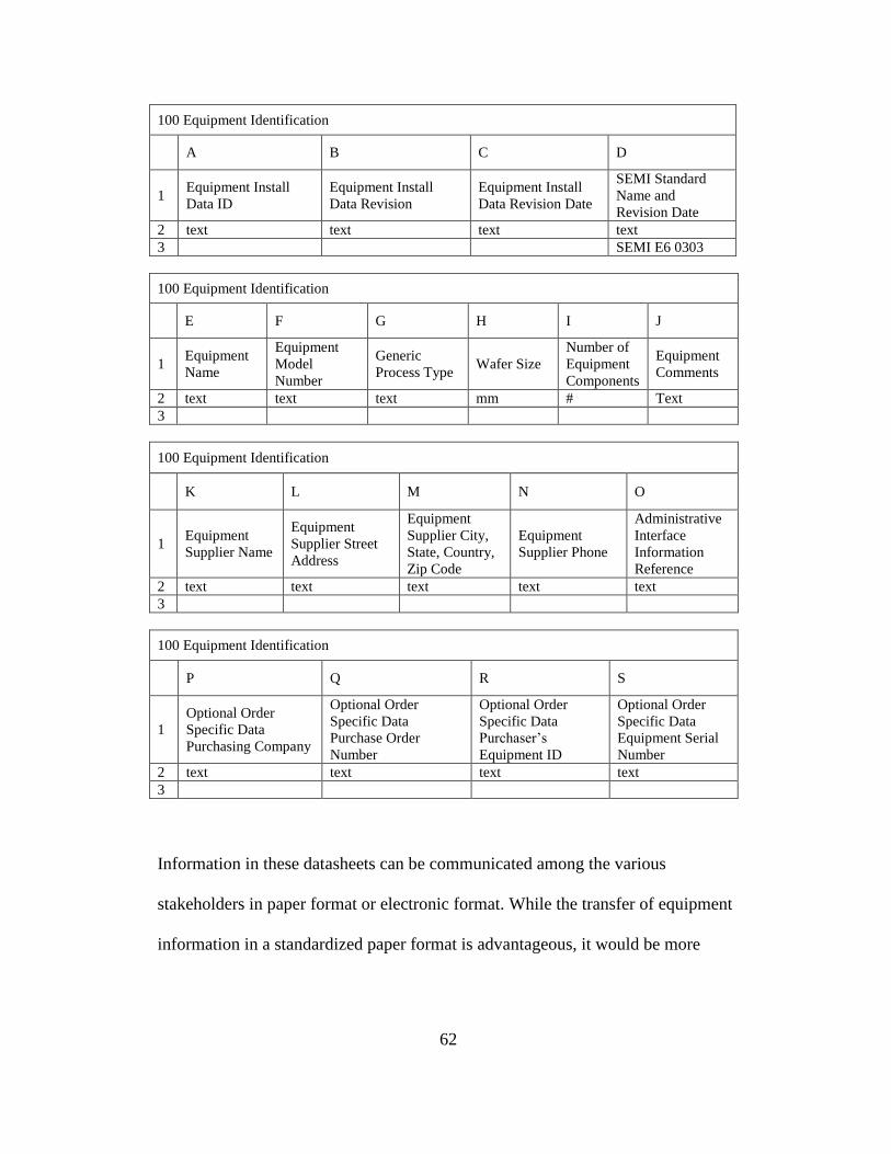
62
100 Equipment Identification
A B C D
1 Equipment Install
Data ID
Equipment Install
Data Revision
Equipment Install
Data Revision Date
SEMI Standard
Name and
Revision Date
2 text text text text
3 SEMI E6 0303
100 Equipment Identification
E F G H I J
1 Equipment
Name
Equipment
Model
Number
Generic
Process Type Wafer Size
Number of
Equipment
Components
Equipment
Comments
2 text text text mm # Text
3
100 Equipment Identification
K L M N O
1 Equipment
Supplier Name
Equipment
Supplier Street
Address
Equipment
Supplier City,
State, Country,
Zip Code
Equipment
Supplier Phone
Administrative
Interface
Information
Reference
2 text text text text text
3
100 Equipment Identification
P Q R S
1
Optional Order
Specific Data
Purchasing Company
Optional Order
Specific Data
Purchase Order
Number
Optional Order
Specific Data
Purchaser‘s
Equipment ID
Optional Order
Specific Data
Equipment Serial
Number
2 text text text text
3
Information in these datasheets can be communicated among the various
stakeholders in paper format or electronic format. While the transfer of equipment
information in a standardized paper format is advantageous, it would be more

63
beneficial for the transfer to be done electronically as manual transmission and
interpretation is time consuming and prone to errors.
2.4.6.2 E6 XML Schema
The production equipment information can be communicated electronically, but
the problem is that different project participants use different software offered by
different software vendors. A research initiative undertaken by CREATE
(Construction Research and Education for Advanced Technology Facilities), a
research consortium for advanced technology facility design and construction at
Arizona State University, developed an E6 Markup Language (E6ML) using
XML technologies. An XML schema was used to model the information in SEMI
E6 standard. The platform independent nature of XML enhances interoperability
between different software applications (Figure 23) (Nagasaravanan 2004).
Figure 23. E6XML Schema (Nagasaravanan 2004).
XML
Schema Export
Module
XML Schema
Export
Module
Tool Vendor
C SEMI E6 Data
Tool Vendor B SEMI E6
Data
Tool Vendor
A SEMI E6
Data
XML
Schema Export
Module
E6ML
Schema
XML
Schema
Import
Module
Fab
Designer/Contractor
Database
XML
Schema
Import
Module
Fab Owner‘s
Database

64
2.4.7 SEMI E51: Guide for Typical Facilities Services and Termination
The objective of SEMI E51, Guide to Typical Facilities Services and Termination
Matrix, is to help provide timely and cost effective tool installation with minimum
impact on existing customer facilities, systems and services and to ensure that the
quality of facilities supplied (e.g., water, gases, chemicals, electricity) is not
compromised once hooked up to the tool (SEMI 2000).
The SEMI E51 provides templates for communicating in a standardized way
utility facilities that are available at a facility. It provides templates for both
‗typical‘ utility ranges as well as ‗Site Specific‘ conditions. Understanding the
typical as well as site specific facilities enables a tool designer to design tools to
suite the site conditions and deliver tools in a more facility ready state. Table 3
below shows the categories of services described in the SEMI E51. Table 4 below
shows a site specific facilities services matrix for water services.
Table 3. Categories of facility data (SEMI 2000). Republished with permission
from Semiconductor Equipment and Materials International, Inc. SEMI © 2011.
Service Category Number Service Category Description
100 Facility Characteristics
400 Electrical Power
500 Water
600 Bulk Chemicals
700 Drains
800 Gases
900 Vacuum
1000 Exhaust

65
Table 4. Site Specific Facilities Service and Termination Matrix (SEMI 2000).
Republished with permission from Semiconductor Equipment and Materials
International, Inc. SEMI © 2011.
Water Service
Supp
ly
Tem
p
Supply
Pressure
(Return
Pressure
where noted)
Filtrati
on
(absolu
te)
Specificat
ion
POC
Material
POC
Fitting
Note
s
Non-Potable
Water
Ultra Pure Water
Deionized Water
Hot Ultra Pure
Water
Fire Protection
Process Cooling
Water
2.5 Building Information Modeling for Semiconductor Manufacturing Facilities
As described above semiconductor manufacturing facilities are very complex and
capital intensive in nature. Construction of these facilities often involves high
levels of uncertainty, strict spending limits, aggressive schedules and fast track
construction. During the various stages of the lifecycle of these facilities different
disciplines come together, generate and use a tremendous amount of building and
process information to support various decisions that enable them to successfully
design, build and sustain these advanced facilities. Design and construction of
semiconductor manufacturing facilities essentially consists of two parts; Base
Build and Tool Install. The base build portion consists of the design and
construction of building structure, shell, the various supply and exhaust systems

66
for HVAC and process requirements such as UPW and electrical systems. The
tool installation portion consists of design and installation of process tools within
the fab building.
2.5.1 Building Information Modeling for Base Build
During the design and construction of the base build portion of the facility
different types of information are used and generated in various forms; from excel
spreadsheets to complex 3D models for analysis. During the programming phase
of the project owners, architects and engineers come together to generate project
requirements for space utilization and capacity planning. Information is captured
using charettes (small paper cards) and eventually transferred into excel or word
documents. The architects and engineers take this information and develop
preliminary design showing space utilization and zoning. They use software such
as Revit and AutoCAD for developing these initial block models. As the design
matures and moves into the schematic design phase these models are further
developed and information from vendors and suppliers regarding properties of
materials and systems are incorporated into the system. Models for this phase are
built using various software such as Revit Architecture, Revit structure and
AutoCAD and information from vendors regarding equipment or material is
obtained as word, pdf documents or excel spreadsheets. As the design develops
and moves into the detailed design phase the building models are further
developed and analyzed in design analysis software for structural strength,
vibration, performance of HVAC systems and energy analysis. The design is
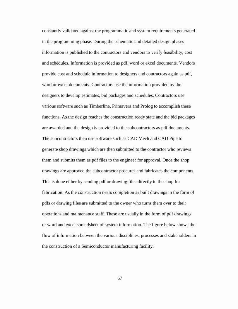
67
constantly validated against the programmatic and system requirements generated
in the programming phase. During the schematic and detailed design phases
information is published to the contractors and vendors to verify feasibility, cost
and schedules. Information is provided as pdf, word or excel documents. Vendors
provide cost and schedule information to designers and contractors again as pdf,
word or excel documents. Contractors use the information provided by the
designers to develop estimates, bid packages and schedules. Contractors use
various software such as Timberline, Primavera and Prolog to accomplish these
functions. As the design reaches the construction ready state and the bid packages
are awarded and the design is provided to the subcontractors as pdf documents.
The subcontractors then use software such as CAD Mech and CAD Pipe to
generate shop drawings which are then submitted to the contractor who reviews
them and submits them as pdf files to the engineer for approval. Once the shop
drawings are approved the subcontractor procures and fabricates the components.
This is done either by sending pdf or drawing files directly to the shop for
fabrication. As the construction nears completion as built drawings in the form of
pdfs or drawing files are submitted to the owner who turns them over to their
operations and maintenance staff. These are usually in the form of pdf drawings
or word and excel spreadsheet of system information. The figure below shows the
flow of information between the various disciplines, processes and stakeholders in
the construction of a Semiconductor manufacturing facility.
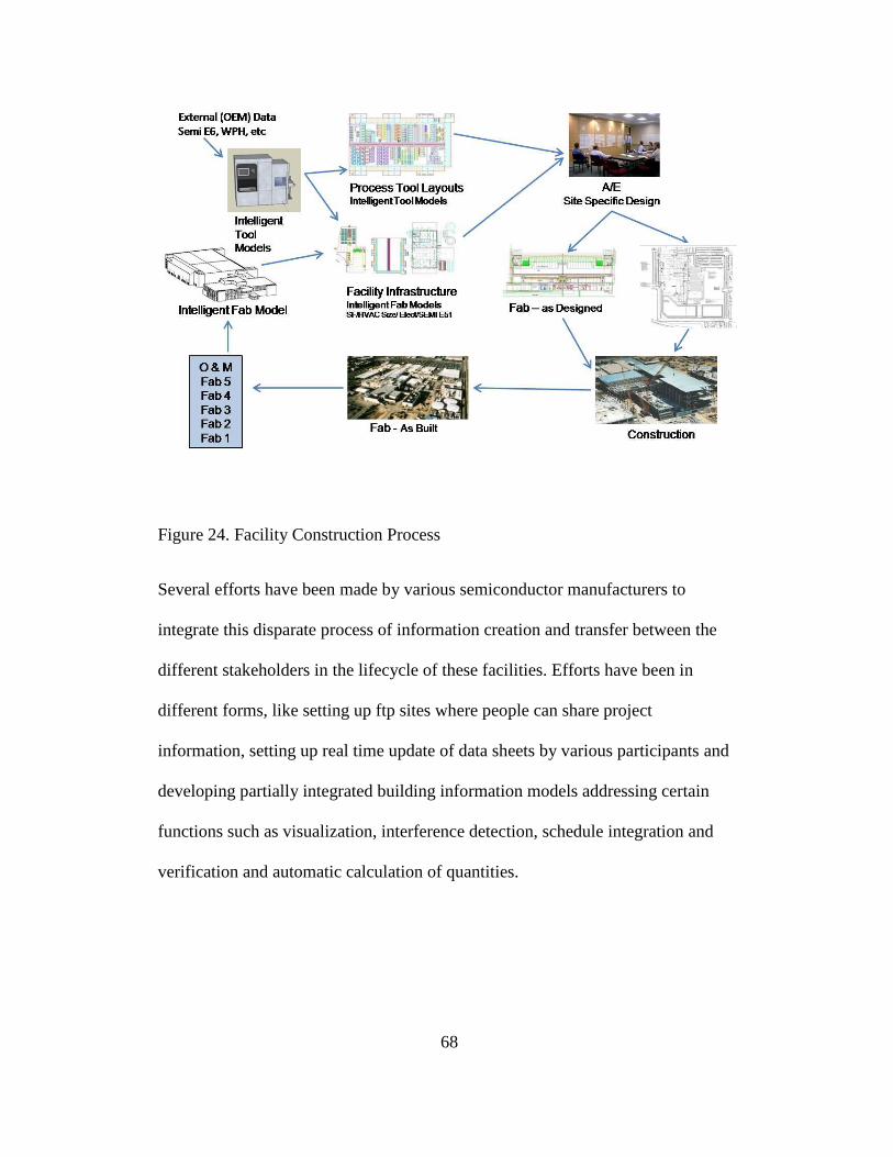
68
Figure 24. Facility Construction Process
Several efforts have been made by various semiconductor manufacturers to
integrate this disparate process of information creation and transfer between the
different stakeholders in the lifecycle of these facilities. Efforts have been in
different forms, like setting up ftp sites where people can share project
information, setting up real time update of data sheets by various participants and
developing partially integrated building information models addressing certain
functions such as visualization, interference detection, schedule integration and
verification and automatic calculation of quantities.

69
2.5.2 Building Information Modeling for Tool Installation
The process of tool installation begins with an understanding of the new process
requirements; new tools, their composition and requirements. The owners design
team gets the information regarding the new tools; the utilities they require, sizes
and output from the tool suppliers usually in the form of hard copies, pdfs or
spreadsheets. The owner‘s industrial engineers create a generic master tool design
package by recreating the production equipment and the utilities that connect to it
in CAD software. A soft copy of the generic master design provided to the
owner‘s local design team which along with the facility model from the facility
designer forms the basis for developing a location specific design for a specific
facility project. The location specific design shows the location plan/layout of the
equipment in the fab in relation to support equipment if any in the sub fab,
references the tool and auxiliary systems to the physical world and the utility
source point of connections. Throughout the several iterations of the tool design,
information pertaining to the tool in terms of utility requirements at the point of
use and facility provision for utilities at the source is communicated between the
tool supplier, facility designer and tool layout designer. The tool and facility
utility information is manually reentered several times in different applications.
The engineering design firm then uses the location specific design provided to the
engineers to develop the schematic diagrams. The Schematics are grouped by
electrical, gases, wet process and mechanical. They indicate relative arrangement
of utilities and systems and show manifolding and common feeds.

70
The owner or construction management firm provides hard copies or soft copies
(pdfs) to the subcontractors to develop the detailed design. The trade
subcontractors then develop the detailed design often recreating the tools and the
schematics and develop them into detailed 2D/3D routing drawings, coordinate
them to check for interferences with basebuild systems.
The tool installation process involves the collection and collation of a large
amount of information to successfully integrate the semiconductor manufacturing
tools into facilities. Information gathering, qualification and dissemination is the
most crucial part of tool installation. Preparing for the tool installation process
involves validating the utility matrix (tool utility requirements), the facilities data
sheets (facility utility provisions), tool position on layout, tool automation, safety
etc. The tools install team again requests this information from the tool suppliers
and facility designers, then recreates and adjusts the information to suit its
construction management system to validate the data prior to installation. A
possible example of a data exchange between tool installation designers and tool
installation contractors is shown in the figure below. These include three iterated
exchanges: (1) first to provide the tool installation design to the tool installation
contractor (ST-1 and ST-2), (2) the contractor analyzes the design and develops a
cost model and suggested revisions for improved installation (ST-3 and ST-4), (3)
the designer and contractor exchange information, coordinating details with the
rest of the building systems, reflecting design intent (ST-5 and ST-6). As can be

71
seen, coverage of all relevant domain exchanges will require hundreds of
workflows, each with different intent and data.
Figure 25. Semiconductor Tool Design and Installation Process

72
3. METHODOLOGY
3.1 Hypothesis
Is it possible to build an intelligent data rich model for both the basebuild and tool
installation portions of a semiconductor manufacturing facility that carries the
different kinds of information that the various stakeholders in its lifecycle use? Is
it possible to transfer this information seamlessly between the basebuild and tool
install portions of the model and between the various stakeholders through all
phases of its lifecycle?
3.2 Methodology
The design and construction of a semiconductor manufacturing facilities involves
a number of components ranging from the various basebuild systems to different
types of tools and processes. It also involves large number of stakeholders ranging
from tool manufacturers, facility and tool designers to contractors and operators.
To understand and test the possibility of building an intelligent and interoperable
model for the basebuild and tool installation portions of a semiconductor
manufacturing facility, a scenario where information is exchanged between the
equipment supplier, process tool layout designer and facility owner for the
purposes of communicating tool requirements and facility conditions is modeled.
A generic block model of a tool containing points of connections of the various
utilities and their attributes was modeled (Tool Information Model) (see Figure
27). A model of the facility containing the structure and facility water services

73
were modeled (Building Information Model) (see Figure 29). Both the models;
Tool Information Model and Building Information Model were brought together
to create the Tool Layout Design. Figure 26 below shows the various models and
the flow of information needed between them.
Figure 26. Flow of Information between Tool Manufacturer, Facility
Owner/Designer and Tool Layout Designer
3.2.1 Tool Information Model
Tool manufacturers and suppliers build and use various types models and
software for purposes of design analyses and manufacturing. One of the softwares
commonly used by tool manufacturers for tool design is Autodesk Inventor. Tool
manufacturers are often reluctant to provide digital models of the tools to tool or
facility designers for various reasons like security purposes (Intellectual Property
IP) to model sizing issues. Sometimes 3D digital models of the tool are provided
in Autodesk Inventor or CAD, however these models do not contain much
intelligence beyond geometries.
Tool Information Model
SEMI E6
Tool Manufacturer
(Autodesk Inventor)
Building Information Model
SEMI E51
Facility Owner/Designer
(Revit MEP)
Tool Layout Design
Tool Layout Designer
(MicroStation)
Scenario 1
Scenario 2
Scenario 3 Scenario 4
Scenario 5 Scenario 6
74
The Autodesk Inventor product line offers a flexible set of software for 3D
Mechanical Design, product simulation, routed systems and mold design with
improved CAD productivity and design communication. The Inventor software
package offers an intuitive parametric design environment for developing
mechanical parts and assemblies. It provides functionality to simulate and test
assembly level motion, deflection and stress to optimize designs. It can help
accelerate the design for routed elements such as tubing piping and flexible hose.
It helps automate certain aspects of injection molds for plastic parts. It integrates
DWG Technology into 3D design thereby facilitating integration with suppliers
who rely on DWG technology and integrating parts assembly and schematic
drawings. It accepts projects from other applications. It has a suite of translators
that help transfer information in industry standards such as IGES and STEP. The
AEC exchange tool creates and publishes simplified 3D representations,
intelligent connection points and additional information using the Autodesk
package files format (.adsk) to facilitate exchange of data with Autodesk REVIT
MEP and REVIT Architecture.
For the purposes of studying the building of an interoperable tool model, a generic
3D model of a tool was built in Autodesk Inventor. It consisted of a generic 3D
model of a tool and the multiple types of utility connections. Information
attributes were attached to each type of utility connection based on the SEMI E6.
Utility connectors such as electrical power, water, bulk chemicals, drains, gasses,
vacuum and exhaust were located on the tool.

75
Attributes for equipment identification were drawn from Data Sheet 100
of the SEMI E6 and attached to the equipment model. Examples of
attributes for equipment identification include equipment name, equipment
model number and generic process type.
Attributes for environmental conditions were drawn from Data Sheet 200
of the SEMI E6 and attached to the equipment model. Examples of
attributes for environmental conditions include equipment component,
cleanroom classification standard and target room temperature.
Attributes for physical characteristics were drawn from Data Sheet 300 of
the SEMI E6 and attached to the equipment model. Examples of attributes
for physical characteristics include number of cleanroom move-in pieces,
biggest move-in piece length and biggest move-in piece width.
Attributes for electrical power were drawn from Data Sheet 400 of the
SEMI E6 and attached to the electrical connector. Examples of attributes
for electrical power connection include electrical power connection
number, utility, type, voltage and frequency.
Attributes for water were drawn from Data Sheet 500 of the SEMI E6 and
attached to the pipe connector for water. Examples of attributes for water
connection include utility type, purity requirements, minimum pressure
and maximum pressure.
Attributes for bulk chemicals were drawn from Data Sheet 600 of the
SEMI E6 and attached to the pipe connector for chemicals. Examples of

76
attributes for bulk chemical connection include utility type, purity
requirements, minimum pressure and maximum pressure.
Attributes for drains were drawn from Data Sheet 700 of the SEMI E6 and
attached to the pipe connector for drains. Examples of attributes for drains
include drain connection number, utility type, maximum discharge
pressure and maximum flow.
Attributes for gases were drawn from Data Sheet 800 of the SEMI E6 and
attached to the pipe connector for drains. Examples of attributes for gases
include Gas connection number, utility type, line source and gas state.
Attributes for vacuum were drawn from Data Sheet 900 of the SEMI E6
and attached to the pipe connector for vacuum. Examples of attributes for
vacuum include vacuum connection number, utility type and minimum
vacuum.
Attributes for exhaust were drawn from Data Sheet 1000 of the SEMI E6
and attached to the duct connector. Examples of attributes for exhaust
include exhaust connection number, minimum static pressure and
maximum static pressure.
An example of the attributes and a description of the attributes from SEMI E6 is
attached as Appendix A to this document.
A 3D block model of the tool was built. The utility connectors were modeled on
the tool using the AEC exchange module. The exhaust connector was modeled on

77
the top part of the tool and the remaining connectors were modeled on either side
of the tool. The AEC exchange module consisted of 5 connector types; cable tray
connector, conduit connector, duct connector, pipe connector and electrical
connector. The electrical connector was used to represent the electrical connection
and the duct connector was used to represent the exhaust connection. Pipe
connector was used to represent water, bulk chemicals, drains, gasses and
vacuum. These connectors have some primary intelligence attached to them; such
as diameter. Other intelligence such as parameters described above per the SEMI
E6 were added as custom user parameters. Figure 27 shows a generic tool block
built in Autodesk inventor with the various utility connectors and attached
attributes.
Figure 27. Tool Information Model

78
3.2.2 Building Information Model
Facility owners and designers use various softwares for the design, analysis,
construction and operation of facilities. The semiconductor manufacturing
industry predominantly uses Building Information Modeling software such as;
AutoCAD, Revit Architecture or MEP. Facility owners and designers sometimes
provide background models to Tool install designers as a DWG file which is a 3D
drawing. They rarely carry information regarding the utilities available at the
facility, so the tool supplier can make sure the tools work in that environment or
the tool install designer can make sure he is optimally locating tools and
efficiently utilizing the resources. This information is usually recreated each time
the need arises; be it for the equipment supplier or tool install designer since their
requirement might vary slightly. SEMI has published the SEMI E51 to facilitate
the transfer of facility information to the tool suppliers in a standardized way.
In order to understand the transfer of information from the semiconductor facility
owner to a tool supplier or tool install designer a block model of the shell of a
facility with some basic base build systems was built in Revit. Revit Architecture
was used to build the shell of the building and Revit MEP was used to build the
basebuild system.
3.2.2.1 Revit MEP
Revit MEP is a Building Information Modeling software for the design of
mechanical, electrical and plumbing systems. The software is produced and

79
marketed by Autodesk. It provides for parametric modeling of Mechanical,
Electrical and Plumbing systems. It has features that aid in the analysis of MEP
design system for improved efficiency. It facilitates the creation of construction
documents and exports models for inter-disciplinary coordination.
The facility shell included a fab and subfab level. The subfab level housed the
basebuild boiler system to supply water to the tool located on the fab level. Pipe
was run from the subfab to the fab level distribution port and terminated.
Information pertaining to the water connection from the SEMI E51 was attached
to the termination point. The following image shows a screen shot of the Tool
Information Model from supplier imported into Revit MEP and pipe drawn from
facility supply equipment to tool.
Figure 28. Tool Information Model from supplier imported into Revit MEP

80
Figure 29. Building Information Model
In order to examine the robustness of the IFC in providing a mechanism for the
transfer of facility information the IFC Model exported from REVIT MEP was
imported into Revit Architecture. This transfer facilitated the transfer of 3D data
but resulted in the loss of facility utility information that was added in Revit MEP
from the E51. The following image shows BIM from Semiconductor
manufacturer exported to IFC and imported to Revit Architecture to examine
information flow.

81
Figure 30. BIM from Semiconductor Manufacturer Exported to IFC and imported
to Revit Architecture

82
3.2.3 Tool Layout Design – Tool Information Model + Building Information
Model
Tool Layout Design involves utilizing detailed information pertaining to the tools
as well as the facility to produce tool layouts. Industrial engineers designing tool
layouts bring together the tool model provided by the supplier and the building
model provided by the facility designer to produce tool layouts. Several tools of
the same type or different type depending on the process and the required
performance are populated in the facility model. As the design evolves with each
iteration tool requirements and facility provisions are adjusted to produce the
most efficient tool layout with optimal tool and facility requirements and
provisions. Automated transfer of spatial and non spatial information pertaining to
the tool and facility between tool supplier, facility designer and tool layout
designer through an integrated model ensures data consistency, reduces
redundancy and expedites the tool layout design process.
Tool layout designers use several 2D and 3D software for tool layout design.
Softwares such as 2D/3D AutoCAD, Bentley MicroStation, AutoPLANT
Equipment, Bentley PlantSpace Equipment or Bentley OpenPlant Modeler can be
used for tool layout design.
To create a tool layout design the tool model built in Autodesk Inventor and
facility model built in Revit Architecture/Revit MEP needed to be imported into
MicroStation. Since the common drawing export formats from Autodesk Inventor

83
and Import/Open formats into MicroStation were DWG, DXF , STEP and IGES.
The tool model was imported into MicroStation as a DWG file. The common
drawing export formats from Revit MEP and Import/Open formats into
MicroStation were DWG, DWF, STEP and IGES. The facility model was
imported into MicroStation as a DWG file. The tool model imported from
Inventor was multiplied and populated within the facility model imported from
Revit MEP in MicroStation to generate the tool layout. During the import process
using the DWG format only the 3 dimensional geometric model of the tool and
the facility were imported into MicroStation. All the intelligence attached to the
SEMI E6 and SEMI E51 was lost during the import process. The figure below
shows a screenshot of the tool layout design in MicroStation.
Figure 31. Tool Layout Design (Enlarged image attached as Appendix D)

84
Bentley Openplant, PlantSpace and AutoPLANT suite of products are popular
solutions used by the process industry for plant design and engineering. The
Bentley Open Plant Modeler V8i is a Microstation V8i based 3D modeling
software that is built upon the ISO15926 as its core data model and is used for the
design of process plants and associated disciplines. The Open Plant Modeler is
open and can be used to produce iRING models that can be used by other
applications that use the ISO 15926 data standard. However most design software
for the process industry such as PlantSpace and AutoPLANT do not import or
export IFC formats.

85
4. RESULTS
4.1 Scenario – 1 Export of the Tool Information Model to Facility
Owner/Designer
Figure 32. Scenario 1 Information transfer between Tool Manufacturer and
Facility Owner/Designer
Various formats that Autodesk Inventor provided to export the generic intelligent
tool block into REVIT MEP were explored. Since Autodesk Inventor did not
provide the option of exporting an IFC file, other export options had to be
considered. Autodesk Inventor provided the following export options; DWF ,
DWFx, PDF , BMP, GIF, IGES, JPEG, JT, PNG, SAT, STEP, STL, TIFF,
CATIA V5 (.CATProduct), Parasolid Binary (.xb), Parasolid Text (.xt),
Pro/ENGINEER Granite (.g), Pro/ENGINEER Neutral (.neu) and DWG format.
Through the AEC exchange environment Inventor also provided the proprietary
Adsk format to facilitate exchange of AEC information like MEP connectors to
Revit MEP and Revit Architecture.
Table 3 below shows that most of the above formats are either images (raster)
formats or 2D vector formats or 3D surface and shape formats that just transfer
geometric information. Some of the formats facilitate transfer of information to
Tool Information Model
SEMI E6
Tool Manufacturer
(Autodesk Inventor)
Building Information Model
SEMI E51
Facility Owner/Designer
(Revit MEP)
Scenario 1

86
specific software programs like Catia or Pro E. One of the formats, STEP is a
product model data format that carries object properties and relations between
objects apart from geometry information. While the ISO-STEP has several
application protocols for various industries and domains, it does not have one for
industrial facilities (AP241 for industrial facilities has been proposed but under
consideration by the committee) (Eastman et al. 2008). Hence the proprietary
Adsk format had to be used to export the model to Revit MEP and Architecture.
Revit MEP imported the Adsk tool model. Even though the Adsk was AutoCADs
own proprietary format to facilitate AEC exchange, the connectors on the tool
were successfully imported but the E6 information added as custom parameters
were not imported.

87
Table 5. Summary of the most common exchange formats in the AEC area
(Eastman et al. 2008).

88
4.2 Scenario 2 - Import of the Building Information Model from Facility Owner to
Tool Manufacturer
Figure 33. Scenario 2 Information transfer from Facility Owner/Designer to Tool
Manufacturer
Autodesk Inventor imports the following file types; Alias (wire), Catia V5 files -
CATPart (part), CATProduct (assembly), JT, Pro E files prt (part) (up to version
4.0),asm (assembly) (up to version 4.0), g (Granite) (up to version 5.0), neu
(Neutral), Parasolid files x_t (text), x_b (binary), SolidWorks prt, sldprt (part),
sldasm (assembly), UGS NX prt (part), prt (assembly), DWG, STEP, IGES and
DWG. While many of the import options are from specific software such as Catia,
ProE and Solidworks. Inventor offers imports in the generic STEP, IGES, DWF
and DWG. While IGES and DWF are just 3D Surface and shape formats and
DWG is a 2D vector format, STEP did not have any application protocols for
industrial plants. Various export mechanisms for the export of an intelligent data
model from Revit MEP were also explored. Revit exports its files in various
formats such as DWG, DWF, PDF, BMP, JPEG, IFC, STEP and IGES. Most of
these formats are 2d vector image formats or 3D object formats that export only
geometry and not intelligence. Of the formats that could export 3D object
Tool Information Model
SEMI E6
Tool Manufacturer
(Autodesk Inventor)
Building Information Model
SEMI E51
Facility Owner/Designer
(Revit MEP) Scenario 2

89
information, the IFC option could be used to export facility information to the tool
supplier (Inventor). Inventor however did not have the capability to import IFC
files. DWG format was used to bring in geometric information regarding facility
into Inventor. This imported model did not carry any intelligence regarding the
facility termination points or requirements.
4.3 Scenario 3 and 4 - Import Tool Information Model and Building Information
Model for Tool Layout Design
Figure 34. Scenario 3 and 4 Information transfer from Tool Manufacturer and
Facility Owner/Designer to Tool Layout Designer
In order to import the Tool Information Model from Autodesk Inventor into
MicroStation for tool layout design the common formats of export from Autodesk
Inventor and MicroStation were explored. The common formats included PDF,
BMP, IGES, JPEG, PNG, STEP, TIFF and DWG format. Similarly most of these
formats are 2d vector image formats or 3D object formats that export only
geometry and not intelligence.
Tool Information Model
SEMI E6
Tool Manufacturer
(Autodesk Inventor)
Building Information Model
SEMI E51
Facility Owner/Designer
(Revit MEP)
Tool Layout Design
Tool Layout Designer
(MicroStation)
Scenario 3 Scenario 4

90
In order to import the Building Information Model from Revit MEP into
MicroStation for tool layout design the common formats of export from Revit
MEP and MicroStation were explored. The common formats include DWG,
DWF, PDF, BMP, JPEG, IFC, STEP and IGES. Again most of these formats are
2d vector image formats or 3D object formats that export only geometry and not
intelligence. The DWG format was chosen to import the Tool Information Model
and Building Information Model into MicroStation. This imported model did not
carry any intelligence regarding the facility termination points.
4.4 Scenario 5 and 6 - Export Tool Layout Design to Tool Manufacturer and
Facility Owner/Designer
Figure 35. Scenario 5 and 6 Information transfer from Tool Layout Designer to
Tool Manufacturer and Facility Owner/Designer
In order to export the optimized Tool Information Model from the Tool Layout
Designer and import it to the Tool Manufacturer the common export and import
formats of MicroStation and Autodesk Inventor were studied. The common
Tool Information Model
SEMI E6
Tool Manufacturer
(Autodesk Inventor)
Building Information Model
SEMI E51
Facility Owner/Designer
(Revit MEP)
Tool Layout Design
Tool Layout Designer
(MicroStation)
Scenario 5 Scenario 6

91
formats included DGN, DWG, DXF, IGES and ParaSolids. Most of these formats
are 2d vector image formats or 3D object formats that export only geometry and
not intelligence. The DWG format was chosen to export the Tool Information
Model to Autodesk Inventor.
In order to export the optimized Building Information Model from the Tool
Layout Designer and import it to the Facility Owner/Designer the common export
and import formats of MicroStation and Revit MEP were studied. The common
formats included DGN, DWG, DXF and IGES. Similarly most of these formats
are 2D vector image formats or 3D object formats that export only geometry and
not intelligence. The DWG format was chosen to export the Building Information
Model to Revit MEP.
4.5 Limited Adoption of Industry Standards IFC /ISO 15926
Through the experimental modeling of tool and facility information in various
software platforms it can be understood that not all software products have
adopted industry standardized export import formats. The Tool Information
Model that was built in Autodesk Inventor could not be exported or imported in
an IFC or ISO 15926 exchange formats. The Building Information Model that
was built in Revit MEP could only be exported and imported IFC format and not
the ISO 15926 thereby creating a one way flow of information. Complete
information pertaining to the tool and the facility could not be imported into

92
Bentley MicroStation because it did not have provisions to import the Autodesk
proprietary Adsk format that Autodesk Inventor exported AEC exchange
information to and it did not have provisions to import the IFC files of the
Building Information Model.
Limited adoption of open industry standards causes the data to be recreated in
each application for every iteration. Recreating the data several times not just
takes additional time and money but also leads to costly errors and omissions.
Software providers must adopt open industry standards to facilitate data
exchange.
4.6 Alignment in the Adoption of Industry standards IFC /ISO 15926
A close look at the import/export formats of the software products reveals that
most of the products are largely aligned with the open industry standard that
pertains to the industry that the product serves. The Autodesk Inventor suite of
products primarily targeted at the product design and manufacturing industry
aligns with CAD/CAM standards such as STEP and IGES. Even though
oftentimes there is transfer of information from and to product and process
applications such as Revit MEP and Bentley MicroStation, they have not adopted
any open data transfer standards that can facilitate this exchange. It is noted that
Revit MEP that is a part of the Autodesk Suite of products exports and imports
IFC formats which supports product models predominantly for the building

93
industry. Bentley‘s MicroStation is a parametric modeling software which is
exports and imports predominantly 2D and 3D formats. Other popular Bentley
software for process industry design and engineering such as AutoPLANT,
PlantSpace and the OpenPlant Modeler are either moving towards using the ISO
15926 as the core data model or provide for project management software that can
convert data to ISO 15926. The semiconductor manufacturing facility model is
unique in that it is a combination of both process and product model. It comprises
of process systems organized within a building which is a product model. The
process of tool layout design requires flow of information between the tool
supplier, facility designer and the tool layout designer. For this to happen the
process tool information which can be represented comprehensively through the
ISO 15926 data standard needs to be interoperable with the facility information
which can be represented more robustly by the IFC data standard. This can be
achieved either by the adoption of both the standards by the software application
involved or creating a universal translator between the ISO 15926 standard and
IFC.
One of the first steps in creating a universal translator between the IFC and ISO
15926 is to create a mapping between the IFC and ISO 15926. The mapping
matches similar classes between the IFC and ISO 15926 so that information from
the IFC can be read by ISO 15926 and vice versa. The SEMI E6 and the E51 can
be used as a baseline with respect to transfer of information between Tool
Information Model and Building Information Model. This can be done manually
by seeing which schemas in both the standards correspond to each other. In some
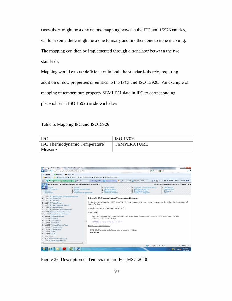
94
cases there might be a one on one mapping between the IFC and 15926 entities,
while in some there might be a one to many and in others one to none mapping.
The mapping can then be implemented through a translator between the two
standards.
Mapping would expose deficiencies in both the standards thereby requiring
addition of new properties or entities to the IFCs and ISO 15926. An example of
mapping of temperature property SEMI E51 data in IFC to corresponding
placeholder in ISO 15926 is shown below.
Table 6. Mapping IFC and ISO15926
IFC ISO 15926
IFC Thermodynamic Temperature
Measure
TEMPERATURE
Figure 36. Description of Temperature in IFC (MSG 2010)
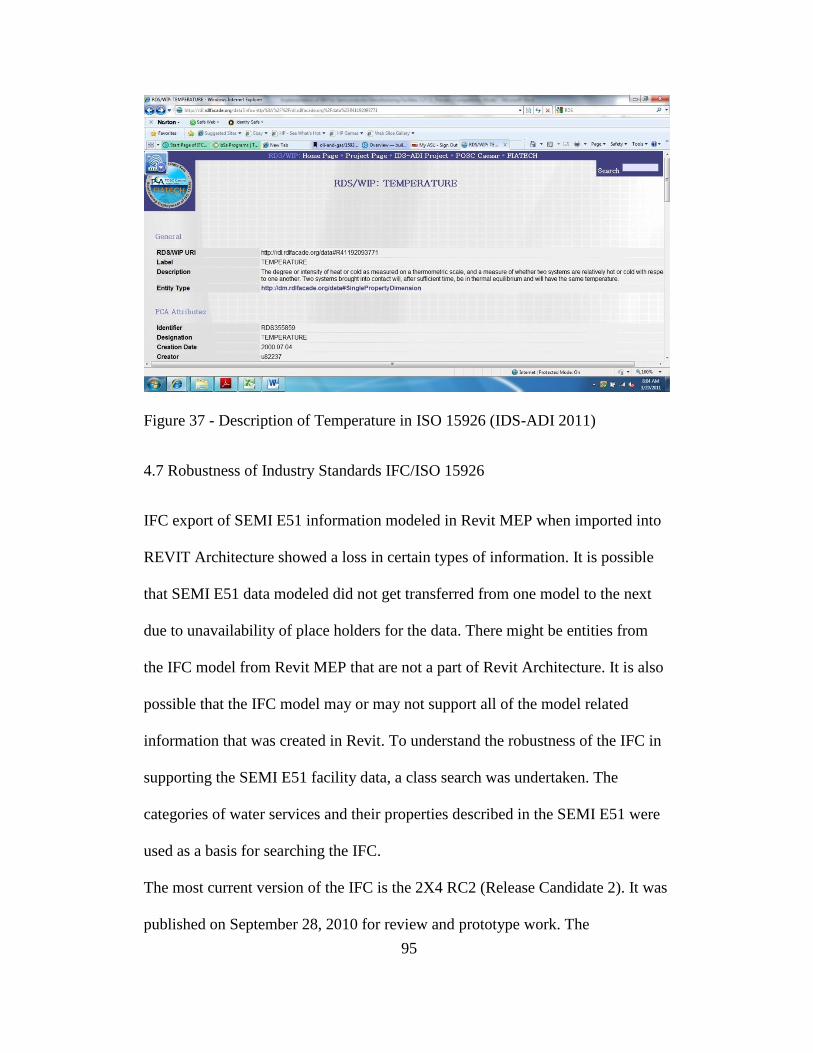
95
Figure 37 - Description of Temperature in ISO 15926 (IDS-ADI 2011)
4.7 Robustness of Industry Standards IFC/ISO 15926
IFC export of SEMI E51 information modeled in Revit MEP when imported into
REVIT Architecture showed a loss in certain types of information. It is possible
that SEMI E51 data modeled did not get transferred from one model to the next
due to unavailability of place holders for the data. There might be entities from
the IFC model from Revit MEP that are not a part of Revit Architecture. It is also
possible that the IFC model may or may not support all of the model related
information that was created in Revit. To understand the robustness of the IFC in
supporting the SEMI E51 facility data, a class search was undertaken. The
categories of water services and their properties described in the SEMI E51 were
used as a basis for searching the IFC.
The most current version of the IFC is the 2X4 RC2 (Release Candidate 2). It was
published on September 28, 2010 for review and prototype work. The

96
specification can be viewed online at the IAI‘s website http://www.iai-
tech.org/downloads/ifc. Upon reviewing the IFC specification, it was understood
that the IFC addresses transfer of information regarding points of connection
through the concept of ports (IFCPort).
IFCPort is associated with IFCElement and it acts as a means to connect one
element to other elements. IFCPort is a supertype of IFCDistributionPort. The
IFC 2x4 specification defines an IFCDistributionPort as an inlet or outlet of a
product through which a particular substance may flow. The substance may be
solid, liquid, gas or electricity for power or communications. Ports may not have
any visible geometry but be captured in the shape representation that indicate
position, orientation or cross section of the connection (MSG 2010)
The type of distribution port is described using the IFCDistributionSystemEnum.
This enumeration identifies the different types of building services. Some
examples of service enumerations specified in the IFC are chilled water,
compressed air and fire protection. This list of enumerations does not contain
some of the water services specified in SEMI E51 water services data sheet. The
water services that need to be added to the IFCDistributionSystemEnum include
Non Potable Water, Ultra-Pure Water, De-ionized water, Hot Ultra-Pure Water
and Process Cooling Water.

97
Property sets have been created for different types of DistributionPorts such as
air-conditioning, domestic hot water and cold water and fire protection. The
SEMI E51 data sheet for water services describes other types of water typically
used in Semiconductor manufacturing facilities such as Non Potable Water, Ultra-
Pure Water, De-ionized water, Hot Ultra-Pure Water and Process Cooling Water.
These additional types of water services need to be described in the IFC and the
Property Sets describing them need to be created.
For example the set of properties used to describe the distribution port type
fireprotection (PSet_DistributionPortTypeFireProtection) are Connection Type,
Connection Subtype, Nominal Diameter, Inner Diameter, Outer Diameter,
Volumetric flow rate, Mass flow rate, Flow Condition, Velocity, Pressure and
IsDesignPoint. The SEMI E51 requires the Fire Protection Water be additionally
described using Filtration and POC Material. Some of these additional properties
such as POC material exist in the IFC (IFCMaterial) and can be added to the fire
protection distribution port property set. Other attributes such as Filtration need to
be added to the IFC. The following table shows the SEMI E51 Water Services
data sheet with the water services and their properties and their corresponding IFC
Classes. It also highlights the water service distribution system, enumeration
property sets and properties that need to be created in the IFC to facilitate the
transfer of information during IFC data model export and import. Analysis of all
the other data sheets in the SEMI E51 against the IFC would provide an
understanding of the existing gaps. Updating the IFC with SEMI E51 information

98
particular to semiconductor manufacturing facilities would provide a more robust
way for information to be interoperable through the IFCs without loss of
intelligence.
Table 7. : Gap Analysis of SEMI E51 Water Services Data Sheet against the IFC
Water Service Entity Described using Status
Non Potable Water IFCDistributionPort
IFC DistributionSystemEnum -
Non Potable Water Add
Ultra Pure Water IFCDistributionPort
IFC DistributionSystemEnum -
Ultra Pure Water Add
Deionized Water IFCDistributionPort
IFC DistributionSystemEnum -
Deionized Water Add
Hot Ultra Pure Water IFCDistributionPort
IFC DistributionSystemEnum -
Hot Ultra Pure Water Add
Fire Protection IFCDistributionPort
IFC DistributionSystemEnum -
Fire Protection Existing
Process Cooling
Water IFCDistributionPort
IFC DistributionSystemEnum -
Process Cooling Water Add
Properties
Supply Temperature
IFC Thermodynamic
Temperature
Measure
IFCFlowDirectionEnum -
Source Existing
Supply Pressure IFCPressureMeasure
IFCFlowDirectionEnum -
Source Existing
Filtration IFCFiltrationMeasure Add
Specification
POC Material IFCMaterial Existing
POC Fitting
IfcProperty
Enumerated Value /
IfcLabel
PEnum_PipeEndStyleTreatment:
BRAZED, COMPRESSION,
FLANGED, GROOVED,
OUTSIDESLEEVE,
SOLDERED, SWEDGE,
THREADED, WELDED,
OTHER, NONE, UNSET Existing
Notes
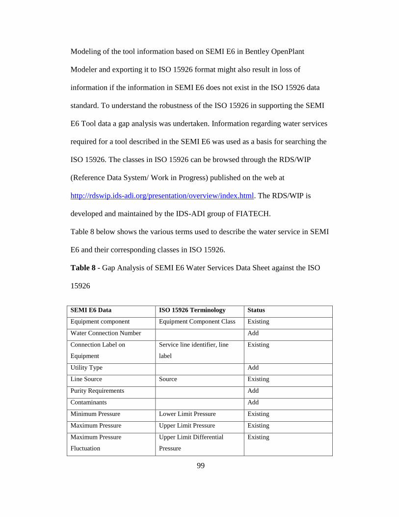
99
Modeling of the tool information based on SEMI E6 in Bentley OpenPlant
Modeler and exporting it to ISO 15926 format might also result in loss of
information if the information in SEMI E6 does not exist in the ISO 15926 data
standard. To understand the robustness of the ISO 15926 in supporting the SEMI
E6 Tool data a gap analysis was undertaken. Information regarding water services
required for a tool described in the SEMI E6 was used as a basis for searching the
ISO 15926. The classes in ISO 15926 can be browsed through the RDS/WIP
(Reference Data System/ Work in Progress) published on the web at
http://rdswip.ids-adi.org/presentation/overview/index.html. The RDS/WIP is
developed and maintained by the IDS-ADI group of FIATECH.
Table 8 below shows the various terms used to describe the water service in SEMI
E6 and their corresponding classes in ISO 15926.
Table 8 - Gap Analysis of SEMI E6 Water Services Data Sheet against the ISO
15926
SEMI E6 Data ISO 15926 Terminology Status
Equipment component Equipment Component Class Existing
Water Connection Number Add
Connection Label on
Equipment
Service line identifier, line
label
Existing
Utility Type Add
Line Source Source Existing
Purity Requirements Add
Contaminants Add
Minimum Pressure Lower Limit Pressure Existing
Maximum Pressure Upper Limit Pressure Existing
Maximum Pressure
Fluctuation
Upper Limit Differential
Pressure
Existing

100
Minimum Pressure
Differential
Lower Limit Differential
Pressure
Existing
Idle Average Flow Add
Process Average Flow Add
Maximum Flow Add
Maximum Temperature Upper Limit Operating
Temperature
Existing
Minimum Temperature Lower Limit Operating
Temperature
Existing
Equipment Component Fitting
Size
Equipment Component Fitting
Material
Equipment Component Fitting
Type
Drawing Reference
Water Comments
The ISO 15926 supports several terms used in the water services data sheet of the
SEMI E6 (see Table 8). For example terms such as equipment component, line
source, minimum pressure, maximum pressure, maximum pressure fluctuation,
minimum pressure differential, maximum temperature and minimum temperature
are described in the ISO 15926. However terms that describe water services
required for semiconductor tools such as purity requirements, contaminants, idle
average flow and process average flow need to be added to the ISO 15926. A
similar exercise can be undertaken for all the other data sheets in the SEMI E6.
The terms identified through the gap analysis can be added to the ISO15926. The
resulting ISO15926 standard will then provide a basis for exchanging process tool
information without loss of data.

101
5. FUTURE DIRECTION
Interoperability plays a vital role in the successful implementation of Building
Information Modeling for semiconductor manufacturing facilities. It helps in the
transfer of information between the various stakeholders throughout the lifecycle
of the facility. Developing industry standards that facilitate interoperability would
benefit all the participants in the design, construction and maintenance of these
facilities. Advancing the state of industry standards such as the IFCs and ISO
15926 requires involvement at both the industry level and organizational level.
At the industry level all the stakeholders in the lifecycle of the facility need to
come together, share their knowledge and experience and invest their time and
energy to develop open interoperable industry standards. Semiconductor industry
consortia such as SEMI have been developing standards and need to consider
understanding, supporting and integrating with other industry standards such as
IFC and ISO 15926.
At the organizational level it is important to understand the various parts of the
organization that Building Information Modeling affects. Mapping the flow of
information between the various stakeholders can help understand the various
functions that the BIM supports. The semiconductor manufacturing facility is
unique in a way that it consists of the base build and tool install part; in modeling
terms it is a process model within a building model. Different data standards are

102
being developed for data exchange; IFC for the building industry and ISO15926
for the process industry. At an organizational level it is important to understand
and define what parts of the design and construction of semiconductor
manufacturing facilities are better described in the product or building standards
and what parts are better described in process standards. It is also important to
understand the various data standards that affect the lifecycle of the facility such
as programming and operations and maintenance.
5.1 IFC for Semiconductor Manufacturing Facilities
The IFCs are an important building industry data standard that can help in
creating an interoperable Building Information Model for the semiconductor
manufacturing facility. It can be inferred from the above research that the IFCs
need to be developed to support information transfers for the semiconductor
manufacturing facility. For this information transfer to take place three
components need to be in place. The format for information exchange (digital
storage), a specification of which information to exchange and when to exchange
the information (process) and a standardized understanding of what the
information exchanged actually is (terminology). The buildingSMART alliance
supports these three factors through the IFC (Industry Foundation Classes), IDM
(Information Delivery Manual) and IFD (International Framework for
dictionaries).
103
Developing the standards would involve developing business process mapping of
all the functions and areas in the lifecycle of the facility that will be impacted by
the building information model. Figure 26 showing the flow of information
between the tool supplier, facility designer and tool layout designer in the
methodology section of this research is a representation of a process map. The
IDM provides detailed specification of the Business Process Modeling Notation
used to create process maps. Creating these process maps would provide an
understanding of the discrete sets of information that need to be exchanged
throughout the process. This business process as well as the sets of information
that need to be exchanged should to be added to the IDM.
In order for the IFC exchange format to be able to transfer information between
applications, it is important for the standard to contain a description and
placeholder for the information to be transferred. A gap analysis of the IFC needs
to be performed against validated information standards for the semiconductor
manufacturing industry such as the SEMI standards. An example of this gap
analysis is shown in the results section (Page 99) of this research. These gaps
need to be filled by adding the missing information classes to the IFC. The IFC
currently stores the definition of the information classes. In the future the IFD
being the dictionary will take on this role of defining the information and the IFC
will provide the data model (digital storage). The figure below shows a schematic
of the various steps to be taken to advance the IFC, IFD and IDM to support the

104
flow of information in a building information model for a semiconductor
manufacturing facility.
Figure 38. IFC for Semiconductor Manufacturing Facilities
5.2 ISO 15926 for Semiconductor Manufacturing Facilities
The ISO 15926 is an important process industry data standard that can be used to
create an interoperable tool/process industry model. The ISO 15926 standard
needs to be developed to support information transfers for the semiconductor
manufacturing industry. Similar to the IFCs the ISO 15926 supports information

105
transfer by providing the format for information exchange (digital storage)
through Part 2 – Data Model, a specification of which and what information to
exchange (process) through the Part 7 (templates) and AEX Project of FIATECH
and a standardized understanding of what the information exchanged actually is
through Part – 4 RDS WIP.
For the ISO 15926 to facilitate the transfer of process information between
different applications it should have the necessary place holders to carry the
information. The classes that describe data for the semiconductor manufacturing
facilities need to be added to Part-4 Reference Data Library, templates of data
sheets need to be created in Part 7 and the corresponding data model needs to be
developed in Part 2.
The figure below outlines a schematic of the various steps to be taken to advance
the Part 2, Part 4 and Part 7 of the ISO 15926 to support the flow of information
in a process/tool information model for a semiconductor manufacturing facility.
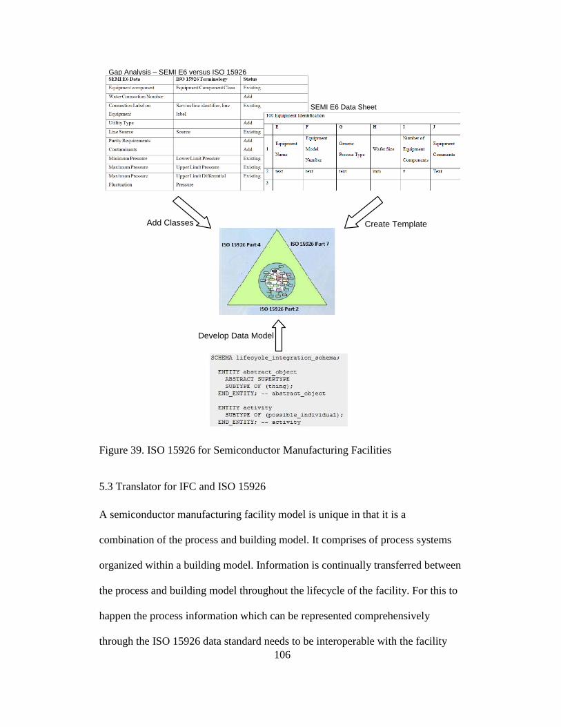
106
SEMI E6 Data Sheet
Gap Analysis – SEMI E6 versus ISO 15926
Add Classes Create Template
Develop Data Model
Figure 39. ISO 15926 for Semiconductor Manufacturing Facilities
5.3 Translator for IFC and ISO 15926
A semiconductor manufacturing facility model is unique in that it is a
combination of the process and building model. It comprises of process systems
organized within a building model. Information is continually transferred between
the process and building model throughout the lifecycle of the facility. For this to
happen the process information which can be represented comprehensively
through the ISO 15926 data standard needs to be interoperable with the facility

107
information which can be represented more robustly by the IFC data standard.
This can be achieved by creating a universal translator between the ISO 15926
standard and IFC. A prototype of a translator was demonstrated at a FIATECH
conference and needs to be made available for business use.
One of the first steps in creating a universal translator between the IFC and ISO
15926 is to create a mapping between the IFC and ISO 15926. The mapping
matches similar classes between the IFC and ISO 15926 so that information from
the IFC can be read by ISO 15926 and vice versa. An example of a mapping is
shown in the results section of this research (page 94) and can be extended to
cover all the information that needs to be exchanged between the two models. A
research project has been undertaken by FIATECH to map the IFC and ISO
15926 with a focus on information exchange for oil and gas facilities. A similar
mapping exercise that maps information exchanged between IFC and ISO15926
needs to be undertaken for semiconductor manufacturing facilities.
108
REFERENCES
Acorn, Bill. ―HVAC Systems – Part 1 and 2‖ (lecture CON-570 – Cleanroom
Construction 1, Arizona State University, Tempe, AZ, 2006).
buildingSMART. 2011, a. ―Model - Industry Foundation Classes (IFC)‖.
buildingSMART International Home of Open BIM.
http://buildingsmart.com/standards/ifc .
buildingSMART. 2011, b. ―Process - Information Delivery Manual (IDM)‖.
buildingSMART International Home of Open BIM.
http://buildingsmart.com/standards/idm.
buildingSMART. 2011, c. ―IFD Library for buildingSMART – Home Page‖.
buildingSMART International Home of Open BIM. http://www.ifd-
library.org/index.php?title=Main_Page.
buildingSMART. 2011, d. ―Model View Definition Summary‖. buildingSMART
International Home of Open BIM. http://www.iai-
tech.org/products/ifc_specification/ifc-view-definition.
Canales, Arnold. ―System Commissioning and Startup‖ (lecture CON-571 –
Cleanroom Construction 2, Arizona State University, Tempe, AZ, 2006).
Chuck Eastman, Teicholz Paul, Sacks Rafael, Liston Kathleen. 2008. BIM
Handbook A guide to building Information Modeling for Owners,
Managers, Designers, Engineers and Contractors. New Jersey: John
Wiley and Sons, Inc.
Evans, Dave. ―Architecture of the Cleanroom Envelope‖ (lecture CON-570 –
Cleanroom Construction 1, Arizona State University, Tempe, AZ, 2006).
109
Fallon, Kristine and Palmer, Mark. 2007. General building information handover
guide: Principles, methodology and case Studies. Madison: National
Institute of Standards and Technology.
FIATECH. 2010. ―Capital Projects Technology Roadmap Overview‖. FIATECH.
http://fiatech.org/tech-roadmap/roadmap-overview.html.
Greg, Abbie. ―Process Tool Hook-up‖ (lecture CON-571 – Cleanroom
Construction 2, Arizona State University, Tempe, AZ, 2006).
Greg, Abbie. ―The Manufacturing Process‖ (lecture CON-570 – Cleanroom
Construction 1, Arizona State University, Tempe, AZ, 2006).
IDS-ADI. 2011. ―iRing The ISO 15926 Real Time Interoperability Network
Grid‖. POSC Caesar and FIATECH IDS-ADI Projects. http://iring.ids-
adi.org/repository/org/ids-adi/camelot/index.html.
ISO (International Organization for Standardization). 1999. ISO 14644-1
Cleanrooms and associated controlled environments—Part 1:
Classification of air cleanliness. New York: American National Standards
Institute.
Jones, Dave. ―Gas and Distributed Chemical Systems‖ (lecture CON-570 –
Cleanroom Construction 1, Arizona State University, Tempe, AZ, 2006).
Khemlani, Lechmi. 2004. ―The IFC Building Model – A Look Under the Hood‖.
AECbytes. http://www.aecbytes.com/feature/2004/IFCmodel.html.
Loper, Tim. ―Ultra-Pure Water Systems‖ (lecture CON-570 – Cleanroom
Construction 1, Arizona State University, Tempe, AZ, 2006).
MSG (Model Support Group). 2010. ―Industry Foundation Classes Release 2x4
(IFC2x4) Release Candidate 2‖. buildingSMART International Home of
Open BIM. http://www.iai-tech.org/ifc/IFC2x4/rc2/html/index.htm.

110
Nagasaravanan, S. P, Mohan Rajat and Chasey, Allan. 2004. E6ML: XML for
advanced technology facilities. Journal of the IEST (46): 36-39.
NIBS (National Institute of Building Sciences). 2007. National Building
Information Modeling Standard Version 1 – Part 1: Overview, principle
and methodology. Washington DC: National Institute of Building
Sciences.
Park, Borinara and Wakefield, Ron. ―Evolution of visualization technology in
construction: Current practices and future implications and their genuine
role (Third International Conference on Information Systems in
Engineering and Construction, Orlando, FL, 2003).
Rachar, Gord. 2009, a. ―Introduction to ISO 15926‖. POSC Caesar Association.
https://www.posccaesar.org/wiki/ISO15926Primer.
Rachar, Gord. 2009, b. ―History to ISO 15926‖. POSC Caesar Association.
https://www.posccaesar.org/wiki/ISO15926Primer_History.
Rachar, Gord. 2009, c. ―How Does ISO 15926 Work‖. POSC Caesar Association.
https://www.posccaesar.org/wiki/ISO15926Primer_HowItWorks.
Rachar, Gord. 2009, d. ―What Has Been Done to Develop ISO 15926‖. POSC
Caesar Association.
https://www.posccaesar.org/wiki/ISO15926Primer_Implementations_Wha
tBeenDone.
Roger Grant, CSI (Construction Specifications Institute) and IFD (International
Framework for Dictionaries) Library Group. 2008. ―IFD White Paper‖.
IFD Library for buildingSMART. http://www.ifd-
library.org/images/IFD_Library_White_Paper_2008-04-10_I_.pdf.

111
SEMI (Semiconductor Equipment and Materials International). 2000. SEMI E51
0200 Guide for typical facilities services and termination matrix.
California: Semiconductor Equipment and Materials International.
SEMI (Semiconductor Equipment and Materials International). 2003. SEMI E6
0303 Guide for semiconductor equipment installation documentation.
California: Semiconductor Equipment and Materials International.
Teicholz, Paul. 2001. US construction labor productivity trends 1970-1998.
Journal of Construction Engineering and Management (127): 427.
Treese, Eric. ―Electrical and Life Safety Systems Design Concepts‖ (lecture
CON-570 – Cleanroom Construction 1, Arizona State University, Tempe,
AZ, 2006).
Wermes, Jim. ―Process Tool Accomodation‖ (lecture CON-570 – Cleanroom
Construction 1, Arizona State University, Tempe, AZ, 2006).
Wix, Jefferey. 2008. ―IDM General Overview‖. Information Delivery Manual.
http://www.iai.no/idm/idm_learning/WS1_IDM_Generally.pdf.

112
APPENDIX A
SEMI DRAFT DOCUMENT 3287 - REVISION TO E6, GUIDE FOR
SEMICONDUCTOR EQUIPMENT INSTALLATION DOCUMENTATION.
REPUBLISHED WITH PERMISSION FROM SEMICONDUCTOR
EQUIPMENT AND MATERIALS INTERNATIONAL INC. SEMI © 2011

113

114

115
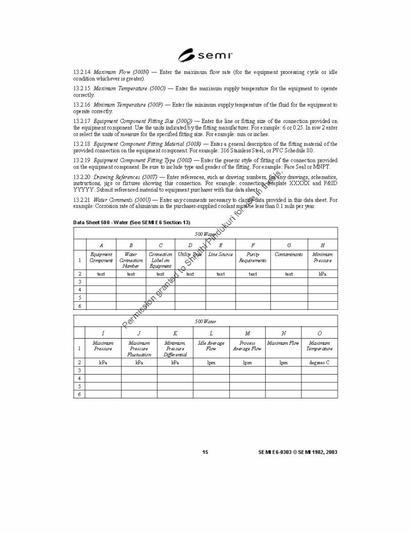
116

117

118
APPENDIX B
SEMI E51-0200 GUIDE FOR TYPICAL FACILITIES SERVICES AND
TERMINATION MATRIX. REPUBLISHED WITH PERMISSION FROM
SEMICONDUCTOR EQUIPMENT AND MATERIALS INTERNATIONAL,
INC. SEMI © 2011.

119

120

121

122
APPENDIX C
SEMI PERMISSION TO PUBLISH PORTIONS OF SEMI E6 0303 AND SEMI
E51 0200

123

124
APPENDIX D
TOOL LAYOUT DESIGN (FIGURE 31)